EP2478831A2 - Unité de positionnement et microscope ophtalmologique - Google Patents
Unité de positionnement et microscope ophtalmologique Download PDFInfo
- Publication number
- EP2478831A2 EP2478831A2 EP12150154A EP12150154A EP2478831A2 EP 2478831 A2 EP2478831 A2 EP 2478831A2 EP 12150154 A EP12150154 A EP 12150154A EP 12150154 A EP12150154 A EP 12150154A EP 2478831 A2 EP2478831 A2 EP 2478831A2
- Authority
- EP
- European Patent Office
- Prior art keywords
- positioning unit
- positioning
- optical element
- microscope
- optical
- Prior art date
- Legal status (The legal status is an assumption and is not a legal conclusion. Google has not performed a legal analysis and makes no representation as to the accuracy of the status listed.)
- Withdrawn
Links
Images


Classifications
-
- G—PHYSICS
- G02—OPTICS
- G02B—OPTICAL ELEMENTS, SYSTEMS OR APPARATUS
- G02B7/00—Mountings, adjusting means, or light-tight connections, for optical elements
- G02B7/001—Counterbalanced structures, e.g. surgical microscopes
-
- A—HUMAN NECESSITIES
- A61—MEDICAL OR VETERINARY SCIENCE; HYGIENE
- A61B—DIAGNOSIS; SURGERY; IDENTIFICATION
- A61B3/00—Apparatus for testing the eyes; Instruments for examining the eyes
- A61B3/0075—Apparatus for testing the eyes; Instruments for examining the eyes provided with adjusting devices, e.g. operated by control lever
-
- G—PHYSICS
- G02—OPTICS
- G02B—OPTICAL ELEMENTS, SYSTEMS OR APPARATUS
- G02B21/00—Microscopes
- G02B21/0004—Microscopes specially adapted for specific applications
- G02B21/0012—Surgical microscopes
-
- G—PHYSICS
- G02—OPTICS
- G02B—OPTICAL ELEMENTS, SYSTEMS OR APPARATUS
- G02B7/00—Mountings, adjusting means, or light-tight connections, for optical elements
- G02B7/02—Mountings, adjusting means, or light-tight connections, for optical elements for lenses
- G02B7/021—Mountings, adjusting means, or light-tight connections, for optical elements for lenses for more than one lens
-
- G—PHYSICS
- G02—OPTICS
- G02B—OPTICAL ELEMENTS, SYSTEMS OR APPARATUS
- G02B7/00—Mountings, adjusting means, or light-tight connections, for optical elements
- G02B7/02—Mountings, adjusting means, or light-tight connections, for optical elements for lenses
- G02B7/023—Mountings, adjusting means, or light-tight connections, for optical elements for lenses permitting adjustment
Definitions
- the invention relates to a positioning unit for positioning an optical unit comprising at least one optical element in a beam path of a microscope between a lens of a microscope and in front of an eye to be observed, wherein the positioning unit comprises a connection device by means of which the positioning unit can be coupled to the microscope.
- Microscopes for performing eye surgery are regularly used for operations in a front region of an eye. If such interventions are to be made in a posterior region of an eye, it is necessary to supplement the microscope with an observation device which enables a focusing of precisely this area of the eye.
- observation devices comprise at least one wide-angle lens or Ophthalmoskopierlinse for wide-angle viewing of the relevant rear part of the eye, the ophthalmoscope lens provides an intermediate image in a beam path in front of a lens of the microscope. This intermediate image can not be focused with the microscope. Depending on Focal length of the additional optics and the eye under consideration, the intermediate image appears sharp at a position closer to the object. To focus the intermediate image requires a shortening of the focal length of the microscope object.
- a height adjustment of the microscope does not change the focal length.
- the intermediate image plane can be placed in the focus of the microscope.
- the microscope In order to be able to focus this intermediate image with the microscope, the microscope must be moved or removed by a distance relative to the ophthalmoscopic lens. This change in height is essentially determined by the individual refractive power of the eye and by the different refractive power of the selected ophthalmoscopy lens.
- the two lenses are held by a positioning unit of the observation device, which is attached directly to the microscope, and can be positioned as required in the beam path, without the need for a substantial adjustment of the microscope during surgery.
- the positioning unit regularly comprises a connection device by means of which the positioning unit can be coupled to the microscope.
- the positioning unit is designed so that the respective lenses can be easily pivoted or inserted into the beam path and removed again therefrom.
- At least one of the lenses can be designed to be adjustable along the beam path of the microscope.
- a linear guide is formed, wherein the lens can be moved by means of a dial with a screw drive.
- the Positioning unit designed so that the ophthalmoscope lens in the direction of the lens of the microscope is substantially resistant to movement, that is, can retreat in a collision with the eye. This is achieved for example by a second linear guide, which also allows a longitudinal displacement of the Ophthalmoskopierlinse.
- the observer or positioning unit be substantially sterile during surgery to prevent potential infection of an eye with, for example, germs.
- a risk of infection is in particular the fact that the observation device is brought relatively close to the eye in an operation.
- the possibility of infection of the patient's eye by an insufficient prepared positioning unit is precluded by the use of a sterile disposable positioning unit.
- It is therefore customary to sterilize the relevant observation device or positioning unit before an operation for example by steam sterilization.
- it is absolutely necessary to design all components of the observation device or positioning unit with the exception of possibly existing seals made of elastic materials such as rubber, of metal or glass.
- the observation devices or positioning units known from the prior art have a number of disadvantages.
- a weight of the observation device which can be adapted to the microscope, for example on an adapter plate screwed to the microscope, is relatively high and interferes with an operation of the observation device during an operation.
- the linear guides are difficult to seal or sterilize. In the threads of the screw drive water or steam is difficult to penetrate in a steam sterilization, so that after steam sterilization can still be undesirable water residues or germs in the threads.
- a quality of sterilization depends, among other things, on a water quality in a steam sterilizer.
- an observation device or a positioning unit is to be sterilized after each use, so that the observation device or positioning unit can not be used for eye operations following the use directly due to the sterilization times.
- the present invention is therefore based on the object to propose a positioning unit and an observation device, their production costs are reduced so much that can be dispensed with a re-sterilization.
- the positioning unit according to the invention for positioning an optical unit comprising at least one optical element in a beam path of a microscope between a lens of the microscope and in front of an eye to be observed comprises a connection device by means of which the positioning unit can be coupled to the microscope, wherein the positioning unit is at least partially made of plastic material is formed.
- the manufacturing cost of the positioning can be significantly reduced.
- essential, mandatory for a mechanical function components of the positioning for example, in an injection molding process, can be produced inexpensively.
- the cost savings that can be achieved by the use of plastic material make it possible to completely dispense with a reuse of the positioning unit and to dispose of the positioning unit after use. This results in further cost advantages, since there are no costs for processing and maintenance.
- the one-time use of the positioning unit further eliminates the risk of contamination associated with the sterilization and possible defects on the positioning unit. Overall, it is envisaged to design as many components of the positioning unit as possible or to manufacture expensive components from a plastics material.
- the positioning unit is thus designed in the form of a sterile disposable article, for example, deliverable in a protective packaging. Since there is no need to think about a recycling or sterilization of the positioning unit, a special one inexpensive plastic material used. A positioning unit formed in this way can also be used, in particular, if special hygiene regulations prohibit the use of resterilized instruments. Furthermore, there are no waiting times for ophthalmic surgery due to instruments being sterilized.
- the positioning unit may comprise a positioning device, by means of which the optical element is movable relative to the microscope in the longitudinal direction of the beam path.
- a mobility of the optical element in the longitudinal direction of the beam path allows adaptation of the optical unit to the eye to be observed and / or an adjustment of the beam path of the microscope to an intermediate image located in the beam path, without having to make adjustments to the microscope.
- the positioning device may be formed of a first double-harmonic transmission and a second double-vibration transmission, wherein the double-vibration transmission may be interconnected by means of a common coupling member.
- the double oscillating gear can each be formed from two rod-shaped wings, which are in turn connected at their ends in each case with a rotary bearing.
- a circular arc-shaped movement of the first double rocker is made possible with the coupling member, wherein the second double rocker can also perform a circular arc-shaped movement in the same direction, such that from both circular movements results in a linear movement in the longitudinal direction of the beam path. Due to this combination of two double oscillating gears, a linear guide for moving the optical element can be completely dispensed with.
- the double swing gears can be designed with simple hinges or pivot bearings, which are much easier to sterilize or seal against linear guides. Also, it requires no special maintenance or Lubrication of the double swing gear and the formation of special guides with correspondingly tight tolerances.
- the wings of the double-action transmission as well as the coupling member can be made in this case, for example, of a plastic material. It is also conceivable to form the necessary for connection pivot bearing made of plastic. Overall, such a manufacturing effort for the positioning can be significantly reduced.
- the first double vibration gear can be connected to the second double vibration gear via a gear transmission such that a movement of the first double vibration gear is transferable to the second double vibration gear by means of the gear transmission.
- a gear transmission such that a movement of the first double vibration gear is transferable to the second double vibration gear by means of the gear transmission.
- the respective teeth may be formed in extension of a rocker of the double-balanced gear.
- the gear transmission and thus a movement coupling of the two double-balanced transmission can be made particularly simple and inexpensive. If the swingarms of the double swinging gears are made of plastic, the gearbox can easily be molded to the respective swingarms.
- the double-vibratory transmission and the gear transmission can be formed integrally together.
- the gear transmission can be formed, for example, between two rockers, which form the respectively necessary teeth.
- the teeth may be formed on the wings or formed by an extension of ends of the wings.
- a one-piece design can be facilitated in particular by the fact that the double-action transmission and the gear transmission essentially in one two-dimensional plane are formed. A production of such plastic parts in an injection molding process is particularly easy.
- the gear transmission has a transmission ratio of 1: 1.
- a first double rocker of the first double-ring gear can be mounted on a connecting bearing member and a second double rocker of the second double-rocker gear can be mounted on a receiving bearing member.
- the connecting bearing member and the receiving bearing member can thus connect the two wings of the double-jointed transmission in a defined distance with each other.
- the connection bearing member may be provided for a rigid attachment in the region of the microscope, wherein the coupling member is movable relative to the terminal bearing member and the receiving bearing member relative to the coupling member and the terminal bearing member.
- the optical element or the optical unit can be provided in the region of the receiving bearing member.
- Both the terminal bearing member and the receiving bearing member may be formed as a plastic material like the double rocker and the coupling member.
- Pivot bearings or rocker bearings of the double oscillating gear can be particularly easily formed by a respective film hinge.
- the double-pivot gears are completely made of plastic, this is particularly advantageous because all the components of the double-jointed transmission can be manufactured in an injection molding process together with the swingarm bearings formed thereon. Next can also be dispensed with the otherwise required installation of the double-balanced transmission.
- the positioning device can comprise an adjusting device, by means of which a position of the optical element can be adjusted.
- the optical element is in the respective desired position, wherein the adjustment or positioning of the optical element can be done for example manually by an operator.
- the adjusting device may for example be formed from at least one adjusting wheel with a worm or eccentric gear.
- the adjusting wheel can be mounted on the connecting bearing member and act on a rocker of the first or second double-ring transmission by means of a worm integrally formed on the adjusting wheel.
- a rotation of the dial then causes a change in the distance of the rocker relative to the dial depending on which portion of the screw is in engagement with the rocker. From the resulting movement of the rocker thus results in a movement of both double-jointed transmission and thus a longitudinal movement of the optical element.
- Such an adjustment can also be made particularly easily from a plastic material.
- the dial can be made with the screw as an injection molded part, which is easily plugged onto a hub. To enable two-sided operation, two oppositely arranged dials can be provided.
- the positioning device can form a safety direction which allows a loose movement of the optical element when a force is exerted on the optical element in the direction of the microscope. That is, the positioning device or safety device may be configured such that when a force is applied to the optical element, for example caused by a collision with the relevant eye, that optical element in the Essentially without resistance in the direction of the lens can be moved.
- the safety device can be designed so that the positioning device and the optical unit by their respective weight, the optical element holds in a lower position in the vicinity of the eye.
- a weight force of the optical unit or positioning device has to be overcome in order to be able to move the optical element.
- a weight force of the optical unit or positioning device has to be overcome in order to be able to move the optical element.
- a weight force thereof is comparatively small, so that only a small force has to be expended for moving the optical element. If the weight is reduced so much that an unwanted movement of the optical element can no longer be ruled out, a spring can be provided on the positioning device for its stabilization, which applies an additional force in the direction of the eye.
- the positioning unit can advantageously comprise a changing device, by means of which the optical element can be moved into and out of the beam path.
- the changing device can be designed so that the optical element can be inserted or swiveled into the beam path.
- the optical element can be pivoted about an axis extending transversely to the beam path together with the positioning unit. It can thus be ensured that the positioning unit and the optical unit do not restrict or obstruct a view in a movement space of the operator above the relevant eye during an operation. It also makes it possible to simply move the optical element in and out of the beam path as needed.
- the changing device may be formed by the connecting device and the positioning device, such that the positioning device is pivotable relative to the connecting device.
- the positioning device can be connected directly to the connecting device in such a way that it can be moved or pivoted relative to the connecting device.
- additional components are not necessarily needed.
- connection device may also be formed of a plastic material.
- the connecting device can be formed directly connected to the microscope firmly connected or alternatively with an adapter device, which in turn is firmly connected to the microscope.
- the connection device can be connected without the aid of additional tools with the adapter device, for example in the manner of a plug connection. If an adapter device is provided on the microscope, this can of course also be formed from a plastic material.
- the changing device is particularly easy to produce when the changing device is designed as a rotary joint, wherein the changing device may comprise at least one locking device by means of which the optical element in a use position in the beam path and / or in a non-use position outside the beam path is adaptable.
- the rotary joint can be formed between the connecting device and the positioning device, so that a pivoting of the positioning device relative to the connecting device is possible.
- the latching device may be formed on the connection device and the positioning device, which in turn may be formed from a latching lug and latching recesses for engagement of the latching lug.
- the detent and the detent recesses may each be integrally formed on the connection device or the positioning device.
- the locking recesses can then be arranged so that the latching nose engages in the use position and the non-use position in each case in a latching recess and thus enables a locking of the optical element or the positioning device.
- the positioning unit is particularly inexpensive and easy to produce, when the positioning unit is completely formed of plastic material.
- the positioning unit can then be formed from only a few components, since it is then possible to produce spatially complex components in, for example, a plastic injection molding process, which would be producible from metal only with great effort.
- a plastic material for example, in particular due to its mechanical properties, a polyamide can be used. It is also possible to supply the entire positioning unit after use without further effort a contaminated hazardous waste.
- the observation device comprises a positioning unit according to the invention and at least one optical unit, wherein the optical unit comprises at least one optical element.
- the optical unit is thus part of the observation device, which in alternative embodiments can have a plurality of optical units. It is also provided that the optical unit has at least one optical element, such as a lens or a prism, wherein a plurality of optical elements may be provided which form a group of lenses or prisms of the optical unit.
- the positioning unit may comprise a receiving device by means of which the optical unit can be adapted to the positioning unit, wherein the optical unit has a holding device for holding and connecting the optical element to the positioning unit Can form recording device.
- the pickup device makes it possible to form the optical unit separately from the positioning unit and, as needed, replace the optical unit while, for example, replacing an eye operation without having to replace the entire positioning unit. It is then also up to an operator to decide to supplement the positioning unit with the optical unit as needed to the observation device.
- the optical element or elements can be held in the intended position by the holding device, wherein the holding device can be formed in connection with the receiving device of the positioning unit, for example in the manner of a plug connection.
- the holding device can be formed in connection with the receiving device of the positioning unit, for example in the manner of a plug connection.
- conventionally formed optical units can also be adapted to the positioning unit.
- the positioning unit can form a holding device for holding the optical element. Consequently, the optical element can be supported directly by the positioning unit without the necessity of forming a receiving device on the positioning unit.
- the holding device may be integrally formed on the positioning device, so that for mounting the optical element, it only has to be inserted into the holding device.
- the holding device and / or the receiving device and / or a connecting device may have at least one connecting element, which is designed so that it is destroyed during a separation of holding device and receiving device and / or connecting device and a microscope.
- a sterilization of the observation device or the plastic components is not possible and not desirable. Consequently, it must be ensured that these components are not reused in further eye operations.
- a connecting element may be provided on the holding device, the receiving device or the connecting device, which is designed, for example, in the manner of a latching element with a predetermined breaking point and thus locked during assembly of the components, so that disassembly is possible only with a zwang conferenceen destruction of the connecting element. A re-assembly and use is made so difficult or impossible. Furthermore, the destroyed connecting element or the relevant component can already be used by a user as being already detected and thus rendered useless.
- the observation device is even cheaper to produce when the optical unit is formed of plastic material.
- one or more optical elements of the optical unit may be made of plastic material of appropriate optical quality.
- the optical unit may also be formed in one piece, in particular if the holding device is formed from the same material as the optical element.
- the optical element can then be formed together with the holding device in an injection molding or pressing process. Accordingly, the optical unit can likewise be produced in such a cost-effective manner, so that the same can be dispensed with for a refurbishment thereof.
- the optical element can be designed as an ophthalmoscope lens, which is used to observe an ocular fundus.
- the optical element may be formed as a Reduzierlinse, which serves to adapt the beam path.
- the observation apparatus alone may use an ophthalmoscope lens or a Ophthalmoscopy lens with a reduction lens as another optical element of another optical unit.
- additional optical units for image reversal and / or permutation of two beam paths can be provided.
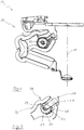
- the observation device 10 comprises optical units 12 and 13, the optical unit 12 being shown only partially here. Of the optical unit 12, only an annular holding device 14 for receiving a reducing lens, not shown here, is shown here.
- the optical unit 13 is formed by an ophthalmoscope lens 15 and a holding device 16.
- the holding device 16 comprises a holder 17 for holding the ophthalmoscope lens 15 and an angle-shaped holder 18 for connection to a receiving device 19 of the positioning device 11.
- the reducing lens and the ophthalmoscopy lens 15, not shown here can be used in a beam path 20 of a microscope microscope, not shown here to be ordered.
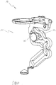
- the positioning unit 11 comprises a connection device 21 and a positioning device 22, wherein between the connection device 21 and the positioning device 22, a changing device 23 for swinging the positioning device 22 and the optical units 12 and 13 into the beam path 20, as from a comparison of Fig. 1 and 5 is apparent, is formed.
- the connecting device 21 is made of a plastic material and is manufactured in one piece by an injection molding process.
- engagement elements 24 are formed for connecting the connecting device 21 with an adapter device of a microscope, not shown here.
- the connecting device 21 forms an axis 25 with a latching nose 26, which can be inserted into a hub 27 of the positioning device 22, and latched as shown.
- the positioning device 22 can now be pivoted about the axis 25.
- a further locking lug 28 is formed on the connecting device 21, which can engage in latching recesses 29 and 30 of the positioning device 22.
- the latching recesses 29 and 30 are formed on the positioning device 22 so that the positioning device 22 in the Fig. 1 shown use position or in the Figure 5 illustrated non-use position by locking with the locking lug 28 can be locked.
- the positioning device 22 is formed from a first double-pivot gear 31 and a second double-pivot gear 32.
- the double vibration gears 31 and 32 are connected to each other by means of a common coupling member 33.
- the first double swing transmission has a rocker 34 and a rocker 35, which are each connected via film hinges 36 to the coupling member 33 and to a terminal bearing member 37.
- the second double-action transmission 32 has rockers 38 and 39, which are each connected by means of film hinges 36 with the coupling member 33 and with a receiving bearing member 40.
- the wings 34 and 38 or ends 41 and 42 formed thereon form a toothed gear 43 with a tooth 44 and a tooth gap 45.
- a movement of the wings 34 and 35 thus causes a transmission of the movement by rolling the tooth 44 in the tooth space 45 on the wings 38 and 39 in a present here ratio of 1: 1 and thus a movement of the ophthalmoscope 15 along the beam path 20th
- the positioning device 22 comprises an adjusting device 46.
- the adjusting device 46 is formed from a retaining element 47 integrally formed on the connecting bearing member 37 with a hub 48.
- a dial 49 with an axis 50 and an integrally formed on the dial 49 screw curve 51 is attached.
- the setting wheel 49 is another dial 52 with a hub 53, such as from Fig.1 seen on the axis 50th attached.
- a rotation of the dials 49 or 52 now causes a rolling of the screw curve 51 on a cam 54, which is integrally formed on the rocker 34.
- the rocker 34 is movable relative to the connection bearing member 37 so that by means of rotation of the dials 49 and 52, the ophthalmoscope lens 15 of the in Fig.1 shown lower working position in the Fig.2 shown upper working position can be moved.
- the worm cam 51 or the adjusting wheel 49 is pressed against the cam 54 by the dead weight of the double oscillating gear 31 and 32 and the optical unit 13.
- the ophthalmoscope lens 15 can, as in FIG Fig.2 shown to be moved into the upper working position against the aforementioned weight without the need for a greater effort would be necessary.
- the cam 54 can be easily released from the screw curve 51 or lifted without the need for another force would be applied.
- a thus formed safety device 56 can effectively prevent possible injuries in a collision with an eye.
- the double-pivot gears 31 and 32 are integrally formed together with the holding member 47 from a plastic material.
- the dials 49 and 52 are also each formed of a plastic material.
- the holding device 14 is also formed of plastic material, wherein the holding device 16 is made of metal and is provided for sterilization and recycling.
- the positioning device 22 further comprises a second receiving device 55 on the connection bearing member 37 to which the annular holding device 14 can be infected.
- a holding device and ophthalmoscope lens not shown here To use plastic material.
- the spring elements 57 press on the holder 18 from above.
- the spring elements 57 are designed so that they are destroyed when the holder 18 is removed from the receiving device 19.
- only a single spring element can be formed here.
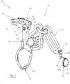
- a synopsis of Fig.6 and 7 shows a further observation device 59 with a positioning unit 60 and a connecting device 61 on the positioning unit 60.
- a holding device 62 is formed for receiving a Reduzierlinse not shown here.
- a connecting device 63 of the positioning unit 60 as in FIGS Fig.1 to 5 shown optical unit 13 infected.
- a first double-pivot 64 and a second double-pivot 65 are formed in several parts.
- the first double-pivot gear 64 comprises a connecting bearing member 66 on which a dial 67 is rotatably mounted and rockers 68 and 69, which are rotatably mounted like rockers 70 and 71 of the second double-ring gear 65 on a coupling member 72 via respective pin connections 73.
- the rockers 70 and 71 are also rotatably connected to a receiving bearing member via the pin connections 73.
- a tooth 75 is formed, which engages in a tooth space 76 of the rocker 68 and thus forms a toothed gear 77.
- a function of the double-pivot gears 64 and 65 with the adjusting wheel 67 substantially corresponds to the previously described function of the positioning unit of FIGS Fig.1 to 5 ,
- the positioning unit 60 can Because of the simple shape of the components, they can also be formed cost-effectively from metal, with the positioning unit 60 being formed in a predominant part of plastic material here as well.
Landscapes
- Physics & Mathematics (AREA)
- General Physics & Mathematics (AREA)
- Optics & Photonics (AREA)
- Health & Medical Sciences (AREA)
- Life Sciences & Earth Sciences (AREA)
- General Health & Medical Sciences (AREA)
- Surgery (AREA)
- Medical Informatics (AREA)
- Biophysics (AREA)
- Heart & Thoracic Surgery (AREA)
- Engineering & Computer Science (AREA)
- Molecular Biology (AREA)
- Ophthalmology & Optometry (AREA)
- Animal Behavior & Ethology (AREA)
- Biomedical Technology (AREA)
- Public Health (AREA)
- Veterinary Medicine (AREA)
- Chemical & Material Sciences (AREA)
- Analytical Chemistry (AREA)
- Microscoopes, Condenser (AREA)
- Mounting And Adjusting Of Optical Elements (AREA)
- Lenses (AREA)
Applications Claiming Priority (1)
| Application Number | Priority Date | Filing Date | Title |
|---|---|---|---|
| DE102011002940.0A DE102011002940B4 (de) | 2011-01-20 | 2011-01-20 | Positioniereinheit und Beobachtungsvorrichtung |
Publications (2)
| Publication Number | Publication Date |
|---|---|
| EP2478831A2 true EP2478831A2 (fr) | 2012-07-25 |
| EP2478831A3 EP2478831A3 (fr) | 2012-08-29 |
Family
ID=45495740
Family Applications (1)
| Application Number | Title | Priority Date | Filing Date |
|---|---|---|---|
| EP12150154A Withdrawn EP2478831A3 (fr) | 2011-01-20 | 2012-01-04 | Unité de positionnement et microscope ophtalmologique |
Country Status (5)
| Country | Link |
|---|---|
| US (1) | US20130229706A9 (fr) |
| EP (1) | EP2478831A3 (fr) |
| JP (1) | JP5670364B2 (fr) |
| CN (1) | CN102599880B (fr) |
| DE (1) | DE102011002940B4 (fr) |
Families Citing this family (3)
| Publication number | Priority date | Publication date | Assignee | Title |
|---|---|---|---|---|
| US9784564B2 (en) * | 2014-12-19 | 2017-10-10 | Quality Vision International, Inc. | Deployment mechanism for optical measurement system |
| CN106580246B (zh) * | 2016-12-20 | 2018-11-02 | 重庆市希光科技有限责任公司 | 一种眼底检查装置、其制造方法及使用其的成像方法 |
| DE102018127469B4 (de) | 2018-11-05 | 2021-02-04 | Oculus Optikgeräte GmbH | Positioniereinheit und Beobachtungsvorrichtung |
Family Cites Families (13)
| Publication number | Priority date | Publication date | Assignee | Title |
|---|---|---|---|---|
| US3941452A (en) * | 1970-12-04 | 1976-03-02 | Parco Scientific Inc. | Microscopes |
| US6215081B1 (en) * | 1998-08-31 | 2001-04-10 | Brigham Young University | Bistable compliant mechanism |
| US6550734B1 (en) * | 2001-10-15 | 2003-04-22 | Lbp Communications, Inc. | Cantilevered support for wired device |
| DE20215635U1 (de) * | 2002-10-11 | 2002-12-05 | Oculus Optikgeraete Gmbh | Optische Vorrichtung zur lösbaren Befestigung an einem Mikroskop |
| JP4224317B2 (ja) * | 2003-01-30 | 2009-02-12 | 株式会社トプコン | 手術用顕微鏡支持装置 |
| WO2005067808A1 (fr) * | 2004-01-13 | 2005-07-28 | Olympus Corporation | Microscope pour intervention |
| WO2005118022A1 (fr) * | 2004-06-03 | 2005-12-15 | Medela Holding Ag | Ensemble teterelle jetable |
| DE102005062238A1 (de) * | 2005-12-22 | 2007-07-05 | Carl Zeiss Meditec Ag | Ophthalmologisches Messsystem und Verfahren zur Ermittlung der biometrischen Daten eines Auges |
| DE102006047459A1 (de) * | 2006-10-07 | 2008-04-10 | Carl Zeiss Surgical Gmbh | Ophthalmo-Operationsmikroskopsystem |
| DE102008011608A1 (de) * | 2008-02-28 | 2009-09-03 | Carl Zeiss Surgical Gmbh | Vorsatzeinrichtung für eine optische Beobachtungseinrichtung |
| DE202008004018U1 (de) * | 2008-03-20 | 2008-05-21 | Oculus Optikgeräte GmbH | Positioniervorrichtung für ein optisches Element |
| DE102009018114A1 (de) * | 2009-04-20 | 2011-01-05 | Dieter Mann Gmbh | Weitwinkelbeobachtung am Operationsmikroskop |
| DE102011002941B8 (de) * | 2011-01-20 | 2012-10-18 | Oculus Optikgeräte GmbH | Positioniereinheit und Beobachtungsvorrichtung |
-
2011
- 2011-01-20 DE DE102011002940.0A patent/DE102011002940B4/de active Active
-
2012
- 2012-01-04 EP EP12150154A patent/EP2478831A3/fr not_active Withdrawn
- 2012-01-17 JP JP2012006642A patent/JP5670364B2/ja active Active
- 2012-01-19 CN CN201210016829.1A patent/CN102599880B/zh active Active
- 2012-01-20 US US13/354,743 patent/US20130229706A9/en not_active Abandoned
Non-Patent Citations (1)
| Title |
|---|
| None |
Also Published As
| Publication number | Publication date |
|---|---|
| JP2012148078A (ja) | 2012-08-09 |
| DE102011002940A1 (de) | 2012-07-26 |
| DE102011002940B4 (de) | 2016-06-23 |
| DE102011002940A8 (de) | 2012-12-27 |
| CN102599880B (zh) | 2016-04-06 |
| US20130229706A9 (en) | 2013-09-05 |
| EP2478831A3 (fr) | 2012-08-29 |
| CN102599880A (zh) | 2012-07-25 |
| US20130003170A1 (en) | 2013-01-03 |
| JP5670364B2 (ja) | 2015-02-18 |
Similar Documents
| Publication | Publication Date | Title |
|---|---|---|
| EP2478832B1 (fr) | Unité de positionnement et microscope ophtalmologique | |
| EP1227355B2 (fr) | Microscope pour observation à grand angle, notamment de chirurgie ophthalmologique | |
| EP2194411B1 (fr) | Dispositif de montage pour un dispositif d'observation optique | |
| EP0236921B1 (fr) | Dispositif adaptable pour des microscopes | |
| EP3586783A2 (fr) | Support de trocart | |
| WO2010127827A1 (fr) | Objectif à deux directions de visée destiné à un endoscope | |
| EP2080495B1 (fr) | Dispositif destiné au traitement de tissu oculaire | |
| DE102014206513A1 (de) | Stereoskopisches Endoskopsystem und Endoskop, Montageverfahren | |
| DE102012214703A1 (de) | Operationsmikroskop-Objektiv mit einstellbarer Schnittweite | |
| DE102011002940B4 (de) | Positioniereinheit und Beobachtungsvorrichtung | |
| DE4033151A1 (de) | Zweiaeugiges fernglas mit zwei optischen fernrohrsystemen | |
| EP3253272B1 (fr) | Dispositif oculaire et instrument chirurgical comprenant un dispositif oculaire | |
| EP2727519B1 (fr) | Unité de positionnement et dispositif d'observation | |
| DE102011005255A1 (de) | Vorrichtung zur Umschaltung einer Blickrichtung eines Videoendoskops | |
| EP0934548A1 (fr) | Lunette grossissante telescopique binoculaire | |
| WO2009037193A2 (fr) | Dispositif à verre de protection à champ opératoire pour microscope opératoire | |
| DE102018127469B4 (de) | Positioniereinheit und Beobachtungsvorrichtung | |
| EP1548482B1 (fr) | Objectif pour un microscope avec des montures correctives axialement ajustables | |
| DE102018112682A1 (de) | Haltevorrichtung und Verfahren zum Arretieren der Haltevorrichtung | |
| DE102004049368A1 (de) | Operationsmikroskop mit Binokulartubus für Mitbeobachtung | |
| DE3151837A1 (de) | "vorrichtung zur spaltbeleuchtung" | |
| DE2422553C3 (de) | Blickzielanordnung für Augenuntersuchungsgeräte | |
| DE202013104321U1 (de) | Optische Vorrichtung zur kontaktfreien Weitwinkelbeobachtung eines Auges unter einem Mikroskop | |
| EP3538952A1 (fr) | Adaptateur pour faire pivoter un objectif | |
| WO2023006366A1 (fr) | Système de visualisation sans contact pour un microscope chirurgical pour chirurgie oculaire |
Legal Events
| Date | Code | Title | Description |
|---|---|---|---|
| PUAI | Public reference made under article 153(3) epc to a published international application that has entered the european phase |
Free format text: ORIGINAL CODE: 0009012 |
|
| AK | Designated contracting states |
Kind code of ref document: A2 Designated state(s): AL AT BE BG CH CY CZ DE DK EE ES FI FR GB GR HR HU IE IS IT LI LT LU LV MC MK MT NL NO PL PT RO RS SE SI SK SM TR |
|
| AX | Request for extension of the european patent |
Extension state: BA ME |
|
| PUAL | Search report despatched |
Free format text: ORIGINAL CODE: 0009013 |
|
| AK | Designated contracting states |
Kind code of ref document: A3 Designated state(s): AL AT BE BG CH CY CZ DE DK EE ES FI FR GB GR HR HU IE IS IT LI LT LU LV MC MK MT NL NO PL PT RO RS SE SI SK SM TR |
|
| AX | Request for extension of the european patent |
Extension state: BA ME |
|
| RIC1 | Information provided on ipc code assigned before grant |
Ipc: G02B 7/02 20060101ALI20120724BHEP Ipc: A61B 3/13 20060101AFI20120724BHEP Ipc: G02B 7/00 20060101ALI20120724BHEP Ipc: G02B 21/00 20060101ALI20120724BHEP Ipc: A61B 19/00 20060101ALI20120724BHEP |
|
| 17P | Request for examination filed |
Effective date: 20130219 |
|
| 17Q | First examination report despatched |
Effective date: 20160909 |
|
| STAA | Information on the status of an ep patent application or granted ep patent |
Free format text: STATUS: EXAMINATION IS IN PROGRESS |
|
| STAA | Information on the status of an ep patent application or granted ep patent |
Free format text: STATUS: THE APPLICATION IS DEEMED TO BE WITHDRAWN |
|
| 18D | Application deemed to be withdrawn |
Effective date: 20171003 |