EP2478500B1 - Vorrichtung zur lagerung und ausgabe von objekten - Google Patents
Vorrichtung zur lagerung und ausgabe von objekten Download PDFInfo
- Publication number
- EP2478500B1 EP2478500B1 EP10744660.1A EP10744660A EP2478500B1 EP 2478500 B1 EP2478500 B1 EP 2478500B1 EP 10744660 A EP10744660 A EP 10744660A EP 2478500 B1 EP2478500 B1 EP 2478500B1
- Authority
- EP
- European Patent Office
- Prior art keywords
- plug
- tags
- objects
- identification information
- tag
- Prior art date
- Legal status (The legal status is an assumption and is not a legal conclusion. Google has not performed a legal analysis and makes no representation as to the accuracy of the status listed.)
- Active
Links
Images

Classifications
-
- G—PHYSICS
- G07—CHECKING-DEVICES
- G07F—COIN-FREED OR LIKE APPARATUS
- G07F11/00—Coin-freed apparatus for dispensing, or the like, discrete articles
- G07F11/64—Coin-freed apparatus for dispensing, or the like, discrete articles in which the articles are individually suspended from stationary supports
-
- G—PHYSICS
- G07—CHECKING-DEVICES
- G07F—COIN-FREED OR LIKE APPARATUS
- G07F17/00—Coin-freed apparatus for hiring articles; Coin-freed facilities or services
- G07F17/10—Coin-freed apparatus for hiring articles; Coin-freed facilities or services for means for safe-keeping of property, left temporarily, e.g. by fastening the property
-
- G—PHYSICS
- G07—CHECKING-DEVICES
- G07F—COIN-FREED OR LIKE APPARATUS
- G07F7/00—Mechanisms actuated by objects other than coins to free or to actuate vending, hiring, coin or paper currency dispensing or refunding apparatus
- G07F7/06—Mechanisms actuated by objects other than coins to free or to actuate vending, hiring, coin or paper currency dispensing or refunding apparatus by returnable containers, i.e. reverse vending systems in which a user is rewarded for returning a container that serves as a token of value, e.g. bottles
-
- G—PHYSICS
- G07—CHECKING-DEVICES
- G07C—TIME OR ATTENDANCE REGISTERS; REGISTERING OR INDICATING THE WORKING OF MACHINES; GENERATING RANDOM NUMBERS; VOTING OR LOTTERY APPARATUS; ARRANGEMENTS, SYSTEMS OR APPARATUS FOR CHECKING NOT PROVIDED FOR ELSEWHERE
- G07C9/00—Individual registration on entry or exit
- G07C9/00174—Electronically operated locks; Circuits therefor; Nonmechanical keys therefor, e.g. passive or active electrical keys or other data carriers without mechanical keys
- G07C9/00896—Electronically operated locks; Circuits therefor; Nonmechanical keys therefor, e.g. passive or active electrical keys or other data carriers without mechanical keys specially adapted for particular uses
- G07C2009/00936—Electronically operated locks; Circuits therefor; Nonmechanical keys therefor, e.g. passive or active electrical keys or other data carriers without mechanical keys specially adapted for particular uses for key cabinets
Definitions
- the invention relates to a device for storing and dispensing objects according to the preamble of claim 1.
- vending machines are known, from which goods must be transported by motor and pay after payment from a storage compartment to an output shaft. Likewise with a motorized transport device, provisioning machines for valuables work. This process is time consuming.
- patent documents and patents US5172829 . US4631358 . FR2624637 . WO2005096236 . FR2717932 and FR2809214 are known devices for storage and issue of keys.
- the object of the invention is to simplify and accelerate the transfer of stored objects from a closed area to a public area in a device for storing and dispensing objects after an approval test has been carried out.
- the objects to be stored and dispensed are provided with plug-in trailers and the plug-in tags in turn are mounted in plug-in slots.
- plug-in tags and plug-in slots for differently designed objects can be used universally.
- the transfer of an object from the storage container in the output shaft is done by gravity and / or spring force.
- the transfer can therefore be initiated by simple release of the controllable release device.
- the subsequent transfer no longer requires its own drive.
- the release device can therefore be structurally very simple and designed for low maintenance and high reliability and durability.
- the plug-in ducts are oriented inclined relative to their longitudinal center axes to a horizontal and plug-in openings of the plug-in ducts point downwards.
- the plug-in trailer can automatically overcome the initial static friction after release and slide into the output shaft. Likewise, too high a load of the release device is avoided by the weight of a heavy object. The force required for the release can thus be reduced.
- inclined Alignment of the longitudinal center axes of the plug-in slots also several rows of slots can be cascaded vertically to accommodate as many as possible plug-in slots. The installation depth of the device then does not have to be increased.
- controllable release device comprises at each plug-in slot an electromagnetically operable latch which is locked in the deactivated state of the electromagnet under spring force in an annular groove of the inserted plug-in trailer, can be activated by control commands and dug in the activated state of the electromagnet from the annular groove of the plugged plug-in trailer ,
- the controllable release device may be controlled by an input or reading unit in response to an access key.
- the plug-in tags include non-contact readable detection plates with electronically stored identification information and the plug-in slots read devices of the identification information and an evaluation device.
- the evaluation device is connected to the controllable release device and the controllable release device is additionally controlled in dependence of the read identification information of the trailer.
- the association, presence or absence of objects can be checked and tracked per se.
- the contactless reading of information is also possible in case of contamination of the object and is not subject to any mechanical wear of the contacts.
- the reader located at each slot allows specific monitoring of the slots.
- the identification information of stored plug-in trailers can be stored linked or buffered with their local plug-in slot and the plug-in slot of a plug-in trailer to be released can then be released by the controllable release device via the identification information linked to the local slot.
- plug-in slots The storage of objects by means of plug-in connectors in plug-in slots is not limited to predetermined slots. Rather, the slots can be randomly populated. This enables the storage and management of a large number of circulating objects and fast assembly or Replacement of the slots after returning the objects.
- a return device for the objects is connected to the evaluation device, wherein the return device comprises a plug-in shaft with a reading device and an electromagnetically actuated latch.
- the bolt can be activated with the correct identification information of an inserted plug-in trailer and locked in an annular groove of the inserted plug-in trailer and is excavated in the deactivated state.
- the take-back device may comprise a transferring and discharging device of the inserted plug-in trailer with the connected object from a public area into a closed area.
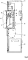
- a device for storing and dispensing objects comprises a storage container 10, which may be designed as a closet.
- the storage container 10 is a mounting frame 12, are arranged on the brackets 14 for the storage of objects 16.
- the brackets 14 are arranged in rows next to each other and cascaded in the embodiment in three floors above the other.
- the brackets 14 consist of stationary plug-in ducts 18 in which plug-in tags 20 connected to the objects 16 are inserted.
- the plug-in slots 18 are aligned with respect to their longitudinal central axes inclined to a horizontal. Plug openings of the plug-in slots 18 are inclined downwards. All openings of the plug-in slots 18 open into an output shaft 22, the bottom is limited by an output tray 24.
- the output tray 24 is accessible through an output flap 26 from the outside.
- each plug-in shaft 18 is equipped with an electromagnetically actuated latch.
- the latch each includes an electromagnet 28 having a spring biased armature 30.
- the armature 30 engages in an annular groove of the plug-in trailer 20 and thus blocks the plug-in tag 20 against pulling out or falling out of the plug-in slot 18.
- the electromagnet 28 is activated, the armature 30 is moved against the force of the spring from the annular groove of the plug-in connector Plug-in trailer 20 excavated, whereupon the trailer 20 is transferred with the attached object 16 from the slot 18 into the output shaft 22 and finally falls under gravity into the output tray 24.
- the control of the electromagnets 28 by a controllable release device 32, which in turn may include control electronics and in addition a keyboard, a card reader, a bar code reader and a display.
- the plug-in tags 20 are equipped with non-contact readable detection plates with electronically stored identification information.
- the plug-in slots 18 include readers of the indent information and the readers are connected to an evaluation device, which in turn is connected to the controllable release device 32 or is part of the controllable release device.
- the release commands targeted electromagnet 28 of the plug-in slots 18 are transmitted.
- the indent information it can be verified that the object 16 with the corresponding plug-in tag 20 actually left the plug-in slot 18.
- the invention can be z.
- a customer receives a PIN code, which he must enter via an input keyboard or an authorization card, which is read automatically by the card reader.
- the control electronics are the indent information known to the PIN code plug-in connector 18 known, whereupon the controllable release device 32 selectively actuates the electromagnet 28 of the corresponding plug-in slot 18 and initiates the output of the object 16 by releasing the plug-in trailer 20 from the plug-in slot 18.
- the object 16 then falls into the output shaft 22 and enters the output tray 24.
- the customer can now through output flap 26 remove the object 16 and use.
- Fig. 2 shows a return unit of the device according to the invention in section.
- a return device 34 is arranged, which is connected to the evaluation device of the device.
- the return device 34 comprises a plug-in shaft 36, which is constructed analogously to the plug-in slots of the output unit may be and includes an electromagnetically actuated latch with an electromagnet 40 and a spring-loaded armature 38. Also in this case, the plug-in shaft 36 is again oriented inclined relative to the longitudinal center axis to a horizontal. The plug hole points downwards.
- the plug-in shaft 36 is integrated into a rotary cylinder 44 driven by means of a geared motor 42. Below the rotary cylinder 44 is located in the interior of the storage container 10, a reammelbox 46th
- a receipt printer 50 with a receipt output tray 52 is still disposed within the storage container 10.
- the device is suitable for taking back objects 16, for example keys of rental cars after returning the vehicle.
- a customer inserts the plug-in tag 20 of an object 16 to be returned into the plug-in slot 36 of the return unit. If it is a valid object 16 to be returned, the ID number of the plug-in tag 20 is read and verified without contact. Thereafter, the solenoid 40 is activated, the armature 38 of the electromagnet 40 slides into the annular groove of the plug-in trailer 20 and holds it firmly.
- the rotary cylinder 44 transfers the object 16 into the interior of the storage container 10, and as soon as it is inside the trailer 20 is released and falls under gravity into the object collection box 46 and thus into the secured area.
- the customer is then printed on the receipt printer 50, a receipt that falls into the receipt output tray 52 and removed from the customer can be.
- the rotary cylinder 44 then returns to the starting position, so that another object can be returned.
- the electromagnet 40 of the slot 36 remains passive and the trailer 20 is not fixed in the slot 36. Rather, it slides out again and again as soon as it is released.
- the armature 38 is inversely controlled here. In the deactivated state, the armature 38 is outside the range of an annular groove and only in the activated state it engages in the annular groove and holds the trailer 20 as long as stuck in the slot 36 until the rotary cylinder 44 is rotated into the interior of the storage container 10 and the trailer 20 can be released with the object 16.
Landscapes
- Physics & Mathematics (AREA)
- General Physics & Mathematics (AREA)
- Warehouses Or Storage Devices (AREA)
- Vending Machines For Individual Products (AREA)
- Coin-Freed Apparatuses For Hiring Articles (AREA)
Description
- Die Erfindung betrifft eine Vorrichtung zur Lagerung und Ausgabe von Objekten nach dem Oberbegriff des Anspruchs 1. Aus der Patentschrift
GB851100 US5172829 ,US4631358 ,FR2624637 WO2005096236 ,FR2717932 FR2809214 - Der Erfindung liegt die Aufgabe zugrunde, bei einer Vorrichtung zur Lagerung und Ausgabe von Objekten die Überführung von gelagerten Objekten aus einem geschlossenen Bereich in einen öffentlichen Bereich nach Durchführung einer Freigabeprüfung zu vereinfachen und zu beschleunigen.
- Diese Aufgabe wird bei einer Vorrichtung nach dem Oberbegriff des Anspruchs 1 durch die im Kennzeichen angegebenen Merkmale gelöst.
- Weiterbildungen und vorteilhafte Ausgestaltungen ergeben sich aus den Unteransprüchen.
- Bei der erfindungsgemäßen Vorrichtung sind die zu lagernden und auszugebenden Objekte mit Steckanhängern versehen und die Steckanhänger ihrerseits sind in Steckschächten gelagert. Dadurch lassen sich einheitliche Steckanhänger und Steckschächte für unterschiedlich gestaltete Objekte universell nutzen.
- Für die Optimierung der Ausgabegeschwindigkeit ist lediglich ein gutes Zusammenspiel zwischen Steckanhängern und Steckschächten nötig. Unterschiede der Objekte sind hingegen ohne Auswirkungen.
- Die Überführung eines Objektes vom Aufbewahrungsbehälter in den Ausgabeschacht erfolgt durch Schwerkraft und/oder Federkraft. Die Überführung kann daher durch einfache Freigabe der steuerbaren Freigabevorrichtung eingeleitet werden. Die anschließende Überführung hingegen benötigt keinen eigenen Antrieb mehr. Die Freigabevorrichtung kann daher konstruktiv sehr einfach gestaltet und auf Wartungsfreiheit und hohe Zuverlässigkeit und Lebensdauer ausgelegt sein. Erfingdungsgemäß sind die Steckschächte bezogen auf ihre Längsmittelachsen geneigt zu einer Horizontalen ausgerichtet und Stecköffnungen der Steckschächte weisen nach unten.
- Durch die geneigte Ausrichtung der Längsmittelachsen der Steckschächte zu einer Horizontalen können die Steckanhänger nach Freigabe selbständig die anfängliche Haftreibung überwinden und in den Ausgabeschacht rutschen. Ebenso wird aber auch eine zu hohe Belastung der Freigabevorrichtung durch das Gewicht eines schweren Objektes vermieden. Die für die Freigabe aufzuwendende Kraft kann so verringert werden. Bei geneigter Ausrichtung der Längsmittelachsen der Steckschächte können außerdem mehrere Reihen Steckschächte vertikal kaskadiert werden, um möglichst eine Vielzahl von Steckschächten unterzubringen. Die Einbautiefe der Vorrichtung muss dann nicht vergrößert werden.
- Gemäß einer Weiterbildung umfasst die steuerbare Freigabevorrichtung an jedem Steckschacht einen elektromagnetisch betätigbaren Riegel, der im deaktivierten Zustand des Elektromagneten unter Federkraft in eine Ringnut des eingesteckten Steckanhängers eingerastet ist, durch Steuerbefehle aktivierbar ist und im aktivierten Zustand des Elektromagneten aus der Ringnut des eingesteckten Steckanhängers ausgehoben ist.
- Bei dieser Ausführung wird für die reine Lagerung der Objekte keine elektrische Energie benötigt. Auch bei Stromausfall bleiben die Objekte an Ort und Stelle. Nur bei Freigabe ist ein kurzer Energiepuls nötig. Danach beginnt ohne weitere Verzögerung die eigentliche mechanische Überführung vom Lager zum Ausgabeschacht. Hierzu ist keine weitere elektrische Energie nötig, sondern lediglich Schwerkraft. Daher ist die Überführungsgeschwindigkeit sehr schnell.
- Die steuerbare Freigabevorrichtung kann durch eine Eingabe- oder Leseeinheit in Abhängigkeit eines Zugangsschlüssels gesteuert sein.
- Dadurch kann nur bei Kenntnis eines Zugangsschlüssels ein zugehöriges Objekt entnommen werden. Manipulationen und Verwechslungen lassen sich so vermeiden. Erfindungsgemäß umfassen die Steckanhänger berührungslos lesbare Detektierplättchen mit elektronisch gespeicherten Identinformationen und die Steckschächte Lesegeräte der Identinformationen und ein Auswertegerät. Das Auswertegerät ist mit der steuerbaren Freigabevorrichtung verbunden und die steuerbare Freigabevorrichtung ist zusätzlich in Abhängigkeit der gelesenen Identinformationen der Steckanhänger gesteuert.
- Durch Lesen und Auswerten von Identinformationen kann das Zuordnen, Vorhandensein oder Fehlen von Objekten an sich geprüft und verfolgt werden. Das berührungslose Lesen von Informationen ist darüber hinaus auch bei Verschmutzung des Objekts möglich und unterliegt keinem mechanischen Verschleiß der Kontakte. Durch das an jedem Steckplatz angeordnete Lesegerät ist die gezielte Überwachung der Steckplätze möglich. Die Identinformationen von gelagerten Steckanhängern kann mit ihrem lokalen Steckschacht verknüpft gespeichert oder zwischengespeichert sind und der Steckschacht eines freizugebenden Steckanhängers ist dann von der steuerbaren Freigabevorrichtung über die mit dem lokalen Steckplatz verknüpfte Identinformationen freigebbar.
- Die Lagerung von Objekten mittels Steckanhängern in Steckschächten ist nicht auf vorher festgelegte Steckplätze beschränkt. Vielmehr können die Steckplätze ungeordnet bestückt werden. Das ermöglicht die Lagerung und Verwaltung einer Vielzahl im Umlauf befindlicher Objekte und eine schnelle Bestückung oder Wiederbestückung der Steckplätze nach Rückgabe der Objekte.
- Bei einer Weiterbildung ist an das Auswertegerät eine Rücknahmevorrichtung für die Objekte angeschlossen, wobei die Rücknahmevorrichtung einen Steckschacht mit einem Lesegerät und einem elektromagnetisch betätigbaren Riegel umfasst. Der Riegel ist bei zutreffender Identinformation eines eingesteckten Steckanhängers aktivierbar und in eine Ringnut des eingesteckten Steckanhängers eingerastet und ist im deaktivierten Zustand ausgehoben.
- Durch die Kopplung der Rücknahmevorrichtung mit dem Auswertegerät ist eine vollständige Verfolgung und Protokollierung von ausgegebenen und im Umlauf befindlichen Objekten möglich. Die Ausgestaltung der Rücknahmevorrichtung ähnlich der Steckschächte ermöglicht, die Rücknahme von Objekten nur auf solche mit gültiger Identnummer zu beschränken. Andere Objekte werden durch Passivität der Rücknahmevorrichtung abgewiesen.
- Da nur eine Rücknahmevorrichtung vorgesehen ist, erfolgt der Lese- und Auswertevorgang verzögerungsfrei, so dass ein Nutzer keine Wartezeiten hinnehmen muss, wie sie bei Multiplexanordnungen sonst vorkommen können.
- Die Rücknahmevorrichtung kann eine Überführungs- und Entladevorrichtung des eingesteckten Steckanhängers mit dem verbundenen Objekt aus einem öffentlichen Bereich in einen geschlossenen Bereich umfassen.
- Dadurch wird ein gültige Rücknahme und anschließende automatische Sicherung des Objektes ermöglicht. Dieser Vorgang kann dem Nutzer quittiert werden, so dass er in kurzer Zeit ein Objekt zurückgeben kann und keine Verzögerungen durch Wege und Wartezeit hinnehmen muss, bis das Objekt in sicherer Verwahrung ist.
- Nachfolgend wird die Erfindung anhand eines Ausführungsbeispiels erläutert, dass in der Zeichnung dargestellt ist.
- In der Zeichnung zeigen:
- Fig. 1
- eine Ausgabeeinheit der erfindungsgemäßen Vorrichtung im Schnitt und
- Fig. 2
- eine Rückgabeeinheit der erfindungsgemäßen Vorrichtung im Schnitt.
- In
Fig. 1 ist eine Vorrichtung zur Lagerung und Ausgabe von Objekten dargestellt. Die Vorrichtung umfasst einen Aufbewahrungsbehälter 10, der als Wandschrank ausgebildet sein kann. In dem Aufbewahrungsbehälter 10 befindet sich ein Montagegestell 12, an dem Halterungen 14 zur Lagerung von Objekten 16 angeordnet sind. Die Halterungen 14 sind in Reihen nebeneinander angeordnet und im Ausführungsbeispiel in drei Etagen übereinander kaskadiert. Die Halterungen 14 bestehen aus stationären Steckschächten 18 in denen mit den Objekten 16 verbundene Steckanhänger 20 eingesteckt sind. Die Steckschächte 18 sind bezogen auf Ihre Längsmittelachsen geneigt zu einer Horizontalen ausgerichtet. Stecköffnungen der Steckschächte 18 weisen schräg nach unten. Sämtliche Öffnungen der Steckschächte 18 münden in einen Ausgabeschacht 22, der unten durch eine Ausgabewanne 24 begrenzt ist. Die Ausgabewanne 24 ist durch eine Ausgabeklappe 26 von außen zugänglich. Zur Fixierung bzw. Freigabe von Objekten 16 ist jeder Steckschacht 18 mit einem elektromagnetisch betätigbaren Riegel ausgestattet. Der Riegel umfasst jeweils einen Elektromagneten 28 mit einem unter Federkraft vorgespannten Anker 30. - Im eingesteckten Zustand eines Steckanhängers 20 greift der Anker 30 in eine Ringnut des Steckanhängers 20 ein und blockiert damit den Steckanhänger 20 gegen Herausziehen oder Herausfallen aus dem Steckschacht 18. Bei Aktivierung des Elektromagneten 28 wird der Anker 30 gegen die Kraft der Feder aus der Ringnut des Steckanhängers 20 ausgehoben, woraufhin der Steckanhänger 20 mit dem daran befestigten Objekt 16 aus dem Steckschacht 18 in den Ausgabeschacht 22 überführt wird und letztlich unter Schwerkraft in die Ausgabewanne 24 fällt. Die Steuerung der Elektromagnete 28 erfolgt durch eine steuerbare Freigabevorrichtung 32, die ihrerseits eine Steuerelektronik und zusätzlich eine Tastatur, einen Kartenleser, einen Barcodeleser und eine Anzeige umfassen kann.
- Ferner sind die Steckanhänger 20 mit berührungslos lesbaren Detektierplättchen mit elektronisch gespeicherten Identinformationen ausgestattet. Die Steckschächte 18 umfassen Lesegeräte der Indentinformationen und die Lesegeräte sind mit einem Auswertegerät verbunden, das wiederum mit der steuerbaren Freigabevorrichtung 32 verbunden ist oder Bestandteil der steuerbaren Freigabevorrichtung ist. Mittels der gespeicherten Indentinformationen und der Lokalinformationen der Steckschächte 18 können die Freigabebefehle gezielt Elektromagneten 28 der Steckschächte 18 übermittelt werden. Durch Überprüfen der Indentinformationen kann darüber hinaus verifiziert werden, dass das Objekt 16 mit dem entsprechenden Steckanhänger 20 auch tatsächlich den Steckschacht 18 verlassen hat.
- Die Erfindung lässt sich z. B. für die Schlüsselausgabe an Kunden eines Mietwagenunternehmens einsetzen. Es wird davon ausgegangen, dass eine Reihe von Steckanhängern 20 mit den entsprechenden Schlüsseln für die Mietwagen verbunden und in Steckschächten 18 gelagert sind. Um an den ihm zugedachten Fahrzeugschlüssel zu gelangen, erhält ein Kunde einen PIN-Code, den er über eine Eingabetastatur eingeben muss oder eine Berechtigungskarte, die vom Kartenleser automatisch gelesen wird. Der Steuerelektronik sind die Indentinformationen des zum PIN-Code zugehörigen Steckanhängers 18 bekannt, woraufhin die steuerbare Freigabevorrichtung 32 gezielt den Elektromagneten 28 des entsprechenden Steckschachtes 18 betätigt und die Ausgabe des Objektes 16 durch Lösen des Steckanhängers 20 aus dem Steckschacht 18 einleitet. Das Objekt 16 fällt daraufhin in den Ausgabeschacht 22 und gelangt in die Ausgabewanne 24. Der Kunde kann nun durch Ausgabeklappe 26 das Objekt 16 entnehmen und nutzen.
-
Fig. 2 zeigt eine Rückgabeeinheit der erfindungsgemäßen Vorrichtung im Schnitt. Im selben oder einem weiteren Aufbewahrungsbehälter 10 ist eine Rücknahmevorrichtung 34 angeordnet, die an das Auswertegerät der Vorrichtung angeschlossen ist. Die Rücknahmevorrichtung 34 umfasst einen Steckschacht 36, der analog zu den Steckschächten der Ausgabeeinheit aufgebaut sein kann und einen elektromagnetisch betätigbaren Riegel mit einem Elektromagneten 40 und einem federbelastetem Anker 38 umfasst. Auch in diesem Fall ist der Steckschacht 36 wiederum bezogen auf die Längsmittelachse zu einer Horizontalen geneigt ausgerichtet. Die Stecköffnung weist nach unten. Der Steckschacht 36 ist in einen mittels eines Getriebemotors 42 angetriebenen Drehzylinder 44 integriert. Unterhalb des Drehzylinders 44 befindet sich im Inneren des Aufbewahrungsbehälters 10 eine Objektsammelbox 46. - Ferner ist noch ein Quittungsdrucker 50 mit einer Quittungsausgabewanne 52 innerhalb des Aufbewahrungsbehälters 10 angeordnet.
- Die Vorrichtung ist zur Rücknahme von Objekten 16, beispielsweise Schlüssel von Mietwagen nach Rückgabe des Fahrzeugs geeignet. Ein Kunde führt den Steckanhänger 20 eines zurückzugebenden Objektes 16 in den Steckschacht 36 der Rückgabeeinheit ein. Handelt es sich um ein gültiges zurückzunehmendes Objekt 16, wird die Indentnummer des Steckanhängers 20 berührungslos gelesen und verifiziert. Daraufhin wird der Elektromagnet 40 aktiviert, der Anker 38 des Elektromagneten 40 gleitet in die Ringnut des Steckanhängers 20 und hält diesen fest. Anschließend überführt der Drehzylinder 44 das Objekt 16 in das Innere des Aufbewahrungsbehälters 10 und sobald er sich im Inneren befindet wird der Steckanhänger 20 freigegeben und fällt unter Schwerkraft in die Objektsammelbox 46 und damit in den gesicherten Bereich. Dem Kunden wird anschließend über den Quittungsdrucker 50 eine Quittung ausgedruckt, die in die Quittungsausgabewanne 52 fällt und vom Kunden entnommen werden kann. Der Drehzylinder 44 kehrt daraufhin in die Ausgangslage zurück, so dass ein weiteres Objekt zurückgegeben werden kann.
- Handelt es sich hingegen um einen nicht indentifizierbaren Steckanhänger 20 so bleibt der Elektromagnet 40 des Steckschachtes 36 passiv und der Steckanhänger 20 wird nicht im Steckschacht 36 fixiert. Vielmehr gleitet er immer wieder hinaus, sobald er losgelassen wird. Im Gegensatz zu den Steckschächten 18 der Ausgabeeinheit wird hier der Anker 38 invers gesteuert. Im deaktivierten Zustand befindet sich der Anker 38 außerhalb des Bereichs einer Ringnut und nur im aktivierten Zustand greift er in die Ringnut ein und hält den Steckanhänger 20 solange im Steckschacht 36 fest, bis der Drehzylinder 44 ins innere des Aufbewahrungsbehälters 10 gedreht ist und der Steckanhänger 20 mit dem Objekt 16 freigegeben werden kann.
Claims (6)
- Vorrichtung zur Lagerung und Ausgabe von Objekten (16) bestehend aus einem Aufbewahrungsbehälter (10), Halterungen (14), einem Ausgabeschacht (22) und einer steuerbaren Halte- und Freigabevorrichtung (28,30,32), wobei die Halterungen stationäre Steckschächte (18) umfassen, in denen mit den Objekten verbundene Steckanhänger (20) eingesteckt sind, wobei die Steckanhänger in den Steckschächten durch die steuerbare Freigabevorrichtung verriegelbar oder freigebbar sind, wobei die Steckanhänger Detektierplättchen mit elektronisch gespeicherten Identinformationen und die Steckschächte Lesegeräte der Identinformationen und ein Auswertegerät umfassen und wobei das Auswertegerät mit der steuerbaren Freigabevorrichtung verbunden ist und die steuerbare Freigabevorrichtung zusätzlich in Abhängigkeit der gelesenen Identinformationen der Steckanhänger gesteuert ist, dadurch gekennzeichnet, dass die Steckschächte bezogen auf ihre Längsmittelachsen geneigt zu einer Horizontalen augerichtet sind und Stecköffnungen der Steckschächte nach unten weisen, dass die mit den Objekten verbundenen Steckanhänger bei Freigabe unter Schwerkraft und/oder Federkraft selbständig aus den Steckschächten in den Ausgabeschacht überführbar sind und dass die Detektierplättchen der Steckanhänger berührungslos lesbare Detektierplättchen sind.
- Vorrichtung nach Anspruch 1, dadurch gekennzeichnet, dass die steuerbare Freigabevorrichtung an jedem Steckschacht einen elektromagnetisch betätigbaren Riegel umfasst, der im deaktivierten Zustand des Elektromagneten unter Federkraft in eine Ringnut des eingesteckten Steckanhängers eingerastet ist, durch Steuerbefehle aktivierbar ist und im aktivierten Zustand des Elektromagneten aus der Ringnut des eingesteckten Steckanhängers ausgehoben ist.
- Vorrichtung nach einem der Ansprüche 1 bis 2, dadurch gekennzeichnet, dass die steuerbare Freigabevorrichtung durch eine Eingabe- oder Leseeinheit in Abhängigkeit eines Zugangsschlüssels gesteuert ist.
- Vorrichtung nach einem der Ansprüche 1 bis 3, dadurch gekennzeichnet, dass die Identinformationen von gelagerten Steckanhängern mit ihrem lokalen Steckschacht verknüpft gespeichert oder zwischengespeichert sind und der Steckschacht eines freizugebenden Steckanhängers von der steuerbaren Freigabevorrichtung über die mit dem lokalen Steckplatz verknüpfte Identinformationen freigebbar ist.
- Vorrichtung nach Anspruch 4, dadurch gekennzeichnet, dass an das Auswertegerät eine Rücknahmevorrichtung für die Objekte angeschlossen ist, wobei die Rücknahmevorrichtung einen Steckschacht mit einem Lesegerät und einem elektromagnetisch betätigbaren Riegel umfasst, der bei zutreffender Identinformation eines eingesteckten Steckanhängers aktivierbar ist und in eine Ringnut des eingesteckten Steckanhängers eingerastet und der im deaktivierten Zustand ausgehoben ist.
- Vorrichtung nach Anspruch 5, dadurch gekennzeichnet, dass die Rücknahmevorrichtung eine Überführungs- und Entladevorrichtung des eingesteckten Steckanhängers mit dem verbundenen Objekt aus einem öffentlichen Bereich in einen geschlossenen Bereich umfasst.
Applications Claiming Priority (2)
| Application Number | Priority Date | Filing Date | Title |
|---|---|---|---|
| DE102009041820.2A DE102009041820B4 (de) | 2009-09-18 | 2009-09-18 | Vorrichtung zur Lagerung und Ausgabe von Objekten |
| PCT/DE2010/000759 WO2011032529A1 (de) | 2009-09-18 | 2010-07-01 | Vorrichtung zur lagerung und ausgabe von objekten |
Publications (2)
| Publication Number | Publication Date |
|---|---|
| EP2478500A1 EP2478500A1 (de) | 2012-07-25 |
| EP2478500B1 true EP2478500B1 (de) | 2017-11-08 |
Family
ID=42760276
Family Applications (1)
| Application Number | Title | Priority Date | Filing Date |
|---|---|---|---|
| EP10744660.1A Active EP2478500B1 (de) | 2009-09-18 | 2010-07-01 | Vorrichtung zur lagerung und ausgabe von objekten |
Country Status (4)
| Country | Link |
|---|---|
| US (1) | US20120226380A1 (de) |
| EP (1) | EP2478500B1 (de) |
| DE (1) | DE102009041820B4 (de) |
| WO (1) | WO2011032529A1 (de) |
Families Citing this family (1)
| Publication number | Priority date | Publication date | Assignee | Title |
|---|---|---|---|---|
| US9441396B2 (en) * | 2013-03-13 | 2016-09-13 | Gideon Gerhardus Buchner | Key safe |
Citations (1)
| Publication number | Priority date | Publication date | Assignee | Title |
|---|---|---|---|---|
| FR2809214A1 (fr) * | 2000-05-17 | 2001-11-23 | Jacques Gilles | Systeme de gestion de porte-clefs et clefs disposes a des emplacements appropries d'au moins un panneau de support |
Family Cites Families (15)
| Publication number | Priority date | Publication date | Assignee | Title |
|---|---|---|---|---|
| GB851100A (en) * | 1958-06-28 | 1960-10-12 | Kurt Wiegandt | A coin-operated automatic vending machine for dispensing individually selectable goods suspended in the machine |
| DE1143659B (de) * | 1960-04-26 | 1963-02-14 | Telefonbau | Halter fuer Packungen, Beutel u. dgl. |
| US4631358A (en) * | 1984-02-14 | 1986-12-23 | Newcome Iii Thomas W | Device and method for article storage and release |
| FR2624637A1 (fr) * | 1987-12-15 | 1989-06-16 | Seron Rene | Distributeur automatique d'objets |
| US5038023A (en) * | 1989-06-28 | 1991-08-06 | C. Itoh Information Systems Development, Inc. | System for storing and monitoring bar coded articles such as keys in a drawer |
| US5172829A (en) * | 1991-09-26 | 1992-12-22 | Siemens Nixdorf Information Systems, Inc. | Automated key dispenser |
| AU7551294A (en) * | 1993-07-29 | 1995-02-28 | Morse Watchmans, Inc. | System and device for storing objects |
| FR2717932B1 (fr) * | 1994-03-28 | 1996-06-21 | Erros | Dispositif pour la délivrance sélective et la récupération contrôlée d'objets. |
| US6505754B1 (en) * | 2000-01-25 | 2003-01-14 | Spectrum Composities, Inc. | Apparatus for automated key retrieval and deposit |
| US6731211B1 (en) * | 2002-11-20 | 2004-05-04 | Micheal A. King | Key control tag |
| US6882282B1 (en) * | 2003-08-07 | 2005-04-19 | Handytrack Key Control Systems, Llc | Object storage and location tracking system with remotely stored and accessible data |
| WO2005096236A1 (en) * | 2004-03-31 | 2005-10-13 | Keysentry Security Systems (Pty) Ltd | The management of key usage |
| US7987020B1 (en) * | 2006-01-27 | 2011-07-26 | Swinea Jr Jessie Donald | Key storage and dispensing assembly and a method for storing and dispensing keys |
| GB2449076B (en) * | 2007-05-09 | 2012-08-22 | Howard Watts | Vending apparatus |
| US8610574B2 (en) * | 2009-06-15 | 2013-12-17 | Gerald Isaac Kestenbaum | Item storage and tracking system |
-
2009
- 2009-09-18 DE DE102009041820.2A patent/DE102009041820B4/de active Active
-
2010
- 2010-07-01 US US13/394,691 patent/US20120226380A1/en not_active Abandoned
- 2010-07-01 WO PCT/DE2010/000759 patent/WO2011032529A1/de not_active Ceased
- 2010-07-01 EP EP10744660.1A patent/EP2478500B1/de active Active
Patent Citations (1)
| Publication number | Priority date | Publication date | Assignee | Title |
|---|---|---|---|---|
| FR2809214A1 (fr) * | 2000-05-17 | 2001-11-23 | Jacques Gilles | Systeme de gestion de porte-clefs et clefs disposes a des emplacements appropries d'au moins un panneau de support |
Also Published As
| Publication number | Publication date |
|---|---|
| DE102009041820A1 (de) | 2011-03-24 |
| DE102009041820B4 (de) | 2015-03-19 |
| EP2478500A1 (de) | 2012-07-25 |
| US20120226380A1 (en) | 2012-09-06 |
| WO2011032529A1 (de) | 2011-03-24 |
Similar Documents
| Publication | Publication Date | Title |
|---|---|---|
| EP0570692B1 (de) | Münzenkassierautomat | |
| EP0613103B1 (de) | Verfahren zum Erfassen von Parkzeiten und/oder Parkgebühren mit Parkkarten | |
| WO2004025579A1 (de) | Rücknahmestation für pfandbelegte oder ausgeliehene objekte | |
| DE10113072A1 (de) | System zur Lagerung und Ausgabe von Objekten | |
| EP2567363B1 (de) | Vorrichtung zum zwischenspeichern von mindestens einem wertscheintransportbehälter | |
| EP2479729B1 (de) | Verfahren zur Steuerung des Transportes von Safebags | |
| WO2009065602A1 (de) | Vorrichtung zur annahme und/oder ausgabe von zahlungsmitteln und/oder zur bearbeitung von wertdokumenten | |
| DE102005014343B4 (de) | Aufbewahrungseinrichtung | |
| DE102009041820B4 (de) | Vorrichtung zur Lagerung und Ausgabe von Objekten | |
| EP3340197A1 (de) | Warenausgabesystem und warenausgabeautomat | |
| EP0189105B1 (de) | Ausgabefach für eine Belegverarbeitungseinrichtung | |
| DE19635483A1 (de) | Verfahren und Vorrichtung zur Überwachung von Gegenständen | |
| EP2211314A1 (de) | Geldautomat mit beschränktem Wartungszugriff auf Geld enthaltende Bereiche | |
| EP3379503A1 (de) | Vorrichtung, anordnung und verfahren zum eingeben und/oder ausgeben von einem oder mehreren wertdokumenten | |
| EP2362360B1 (de) | Münzspeicher mit Speicherkette | |
| EP0261618B1 (de) | Verkaufs- und/oder Dienstleistungsautomat und Identifikationsmittel für die Benutzer von Verkaufs- und/oder Dienstleistungsautomaten | |
| DE102006014432A1 (de) | Schließfacheinrichtung mit biometrischer Identifizierung | |
| EP0924143B1 (de) | Regallager | |
| EP3093072B1 (de) | Verfahren zum sichern von in verschliessbaren kassetten von aktenvernichtern abgelegten dokumenten gegen unberechtigten zugriff nebst anordnung zur durchführung des verfahrens | |
| EP2026289A1 (de) | Fachanlage; Verfahren zur Identifikation einer Person und Auswahl von Funktionen der Fachanlage | |
| DE19518957C1 (de) | Verfahren zum Betrieb einer Tresoranlage und Anordnung zur Durchführung des Verfahrens | |
| DE19917004C1 (de) | Vorrichtung zum Abkassieren eines kontaktlos auslesbaren Informationsträgers | |
| DE102007038185A1 (de) | Fachanlage mit einer Sicherung gegen versehentliches Einschließen | |
| DE9315016U1 (de) | Verriegelbare Aufnahme- und Übergabeeinrichtung zur Aufnahme und Übergabe von Sachen in ein Depot | |
| DE102011114142A1 (de) | Deposit-Wertschutzschrank |
Legal Events
| Date | Code | Title | Description |
|---|---|---|---|
| PUAI | Public reference made under article 153(3) epc to a published international application that has entered the european phase |
Free format text: ORIGINAL CODE: 0009012 |
|
| 17P | Request for examination filed |
Effective date: 20120308 |
|
| AK | Designated contracting states |
Kind code of ref document: A1 Designated state(s): AL AT BE BG CH CY CZ DE DK EE ES FI FR GB GR HR HU IE IS IT LI LT LU LV MC MK MT NL NO PL PT RO SE SI SK SM TR |
|
| DAX | Request for extension of the european patent (deleted) | ||
| 17Q | First examination report despatched |
Effective date: 20130924 |
|
| GRAP | Despatch of communication of intention to grant a patent |
Free format text: ORIGINAL CODE: EPIDOSNIGR1 |
|
| INTG | Intention to grant announced |
Effective date: 20170807 |
|
| GRAS | Grant fee paid |
Free format text: ORIGINAL CODE: EPIDOSNIGR3 |
|
| GRAA | (expected) grant |
Free format text: ORIGINAL CODE: 0009210 |
|
| RBV | Designated contracting states (corrected) |
Designated state(s): AL AT BE BG CH CY CZ DK EE ES FI FR GB GR HR HU IE IS IT LI LT LU LV MC MK MT NL NO PL PT RO SE SI SK SM TR |
|
| REG | Reference to a national code |
Ref country code: DE Ref legal event code: R108 |
|
| AK | Designated contracting states |
Kind code of ref document: B1 Designated state(s): AL AT BE BG CH CY CZ DK EE ES FI FR GB GR HR HU IE IS IT LI LT LU LV MC MK MT NL NO PL PT RO SE SI SK SM TR |
|
| REG | Reference to a national code |
Ref country code: GB Ref legal event code: FG4D Free format text: NOT ENGLISH |
|
| REG | Reference to a national code |
Ref country code: CH Ref legal event code: EP Ref country code: AT Ref legal event code: REF Ref document number: 944839 Country of ref document: AT Kind code of ref document: T Effective date: 20171115 |
|
| REG | Reference to a national code |
Ref country code: IE Ref legal event code: FG4D Free format text: LANGUAGE OF EP DOCUMENT: GERMAN |
|
| REG | Reference to a national code |
Ref country code: NL Ref legal event code: MP Effective date: 20171108 |
|
| REG | Reference to a national code |
Ref country code: LT Ref legal event code: MG4D |
|
| PG25 | Lapsed in a contracting state [announced via postgrant information from national office to epo] |
Ref country code: FI Free format text: LAPSE BECAUSE OF FAILURE TO SUBMIT A TRANSLATION OF THE DESCRIPTION OR TO PAY THE FEE WITHIN THE PRESCRIBED TIME-LIMIT Effective date: 20171108 Ref country code: SE Free format text: LAPSE BECAUSE OF FAILURE TO SUBMIT A TRANSLATION OF THE DESCRIPTION OR TO PAY THE FEE WITHIN THE PRESCRIBED TIME-LIMIT Effective date: 20171108 Ref country code: NO Free format text: LAPSE BECAUSE OF FAILURE TO SUBMIT A TRANSLATION OF THE DESCRIPTION OR TO PAY THE FEE WITHIN THE PRESCRIBED TIME-LIMIT Effective date: 20180208 Ref country code: ES Free format text: LAPSE BECAUSE OF FAILURE TO SUBMIT A TRANSLATION OF THE DESCRIPTION OR TO PAY THE FEE WITHIN THE PRESCRIBED TIME-LIMIT Effective date: 20171108 Ref country code: NL Free format text: LAPSE BECAUSE OF FAILURE TO SUBMIT A TRANSLATION OF THE DESCRIPTION OR TO PAY THE FEE WITHIN THE PRESCRIBED TIME-LIMIT Effective date: 20171108 Ref country code: LT Free format text: LAPSE BECAUSE OF FAILURE TO SUBMIT A TRANSLATION OF THE DESCRIPTION OR TO PAY THE FEE WITHIN THE PRESCRIBED TIME-LIMIT Effective date: 20171108 |
|
| PG25 | Lapsed in a contracting state [announced via postgrant information from national office to epo] |
Ref country code: IS Free format text: LAPSE BECAUSE OF FAILURE TO SUBMIT A TRANSLATION OF THE DESCRIPTION OR TO PAY THE FEE WITHIN THE PRESCRIBED TIME-LIMIT Effective date: 20180308 Ref country code: GR Free format text: LAPSE BECAUSE OF FAILURE TO SUBMIT A TRANSLATION OF THE DESCRIPTION OR TO PAY THE FEE WITHIN THE PRESCRIBED TIME-LIMIT Effective date: 20180209 Ref country code: HR Free format text: LAPSE BECAUSE OF FAILURE TO SUBMIT A TRANSLATION OF THE DESCRIPTION OR TO PAY THE FEE WITHIN THE PRESCRIBED TIME-LIMIT Effective date: 20171108 Ref country code: BG Free format text: LAPSE BECAUSE OF FAILURE TO SUBMIT A TRANSLATION OF THE DESCRIPTION OR TO PAY THE FEE WITHIN THE PRESCRIBED TIME-LIMIT Effective date: 20180208 Ref country code: LV Free format text: LAPSE BECAUSE OF FAILURE TO SUBMIT A TRANSLATION OF THE DESCRIPTION OR TO PAY THE FEE WITHIN THE PRESCRIBED TIME-LIMIT Effective date: 20171108 |
|
| REG | Reference to a national code |
Ref country code: FR Ref legal event code: PLFP Year of fee payment: 9 |
|
| PG25 | Lapsed in a contracting state [announced via postgrant information from national office to epo] |
Ref country code: CZ Free format text: LAPSE BECAUSE OF FAILURE TO SUBMIT A TRANSLATION OF THE DESCRIPTION OR TO PAY THE FEE WITHIN THE PRESCRIBED TIME-LIMIT Effective date: 20171108 Ref country code: SK Free format text: LAPSE BECAUSE OF FAILURE TO SUBMIT A TRANSLATION OF THE DESCRIPTION OR TO PAY THE FEE WITHIN THE PRESCRIBED TIME-LIMIT Effective date: 20171108 Ref country code: CY Free format text: LAPSE BECAUSE OF FAILURE TO SUBMIT A TRANSLATION OF THE DESCRIPTION OR TO PAY THE FEE WITHIN THE PRESCRIBED TIME-LIMIT Effective date: 20171108 Ref country code: EE Free format text: LAPSE BECAUSE OF FAILURE TO SUBMIT A TRANSLATION OF THE DESCRIPTION OR TO PAY THE FEE WITHIN THE PRESCRIBED TIME-LIMIT Effective date: 20171108 Ref country code: DK Free format text: LAPSE BECAUSE OF FAILURE TO SUBMIT A TRANSLATION OF THE DESCRIPTION OR TO PAY THE FEE WITHIN THE PRESCRIBED TIME-LIMIT Effective date: 20171108 |
|
| PG25 | Lapsed in a contracting state [announced via postgrant information from national office to epo] |
Ref country code: RO Free format text: LAPSE BECAUSE OF FAILURE TO SUBMIT A TRANSLATION OF THE DESCRIPTION OR TO PAY THE FEE WITHIN THE PRESCRIBED TIME-LIMIT Effective date: 20171108 Ref country code: PL Free format text: LAPSE BECAUSE OF FAILURE TO SUBMIT A TRANSLATION OF THE DESCRIPTION OR TO PAY THE FEE WITHIN THE PRESCRIBED TIME-LIMIT Effective date: 20171108 Ref country code: SM Free format text: LAPSE BECAUSE OF FAILURE TO SUBMIT A TRANSLATION OF THE DESCRIPTION OR TO PAY THE FEE WITHIN THE PRESCRIBED TIME-LIMIT Effective date: 20171108 Ref country code: IT Free format text: LAPSE BECAUSE OF FAILURE TO SUBMIT A TRANSLATION OF THE DESCRIPTION OR TO PAY THE FEE WITHIN THE PRESCRIBED TIME-LIMIT Effective date: 20171108 |
|
| PLBE | No opposition filed within time limit |
Free format text: ORIGINAL CODE: 0009261 |
|
| STAA | Information on the status of an ep patent application or granted ep patent |
Free format text: STATUS: NO OPPOSITION FILED WITHIN TIME LIMIT |
|
| PG25 | Lapsed in a contracting state [announced via postgrant information from national office to epo] |
Ref country code: MT Free format text: LAPSE BECAUSE OF FAILURE TO SUBMIT A TRANSLATION OF THE DESCRIPTION OR TO PAY THE FEE WITHIN THE PRESCRIBED TIME-LIMIT Effective date: 20171108 |
|
| 26N | No opposition filed |
Effective date: 20180809 |
|
| PG25 | Lapsed in a contracting state [announced via postgrant information from national office to epo] |
Ref country code: SI Free format text: LAPSE BECAUSE OF FAILURE TO SUBMIT A TRANSLATION OF THE DESCRIPTION OR TO PAY THE FEE WITHIN THE PRESCRIBED TIME-LIMIT Effective date: 20171108 |
|
| REG | Reference to a national code |
Ref country code: CH Ref legal event code: PL |
|
| PG25 | Lapsed in a contracting state [announced via postgrant information from national office to epo] |
Ref country code: MC Free format text: LAPSE BECAUSE OF FAILURE TO SUBMIT A TRANSLATION OF THE DESCRIPTION OR TO PAY THE FEE WITHIN THE PRESCRIBED TIME-LIMIT Effective date: 20171108 Ref country code: LU Free format text: LAPSE BECAUSE OF NON-PAYMENT OF DUE FEES Effective date: 20180701 |
|
| REG | Reference to a national code |
Ref country code: BE Ref legal event code: MM Effective date: 20180731 |
|
| REG | Reference to a national code |
Ref country code: IE Ref legal event code: MM4A |
|
| PG25 | Lapsed in a contracting state [announced via postgrant information from national office to epo] |
Ref country code: IE Free format text: LAPSE BECAUSE OF NON-PAYMENT OF DUE FEES Effective date: 20180701 Ref country code: LI Free format text: LAPSE BECAUSE OF NON-PAYMENT OF DUE FEES Effective date: 20180731 Ref country code: CH Free format text: LAPSE BECAUSE OF NON-PAYMENT OF DUE FEES Effective date: 20180731 |
|
| PG25 | Lapsed in a contracting state [announced via postgrant information from national office to epo] |
Ref country code: BE Free format text: LAPSE BECAUSE OF NON-PAYMENT OF DUE FEES Effective date: 20180731 |
|
| REG | Reference to a national code |
Ref country code: AT Ref legal event code: MM01 Ref document number: 944839 Country of ref document: AT Kind code of ref document: T Effective date: 20180701 |
|
| PG25 | Lapsed in a contracting state [announced via postgrant information from national office to epo] |
Ref country code: AT Free format text: LAPSE BECAUSE OF NON-PAYMENT OF DUE FEES Effective date: 20180701 |
|
| PG25 | Lapsed in a contracting state [announced via postgrant information from national office to epo] |
Ref country code: TR Free format text: LAPSE BECAUSE OF FAILURE TO SUBMIT A TRANSLATION OF THE DESCRIPTION OR TO PAY THE FEE WITHIN THE PRESCRIBED TIME-LIMIT Effective date: 20171108 |
|
| PG25 | Lapsed in a contracting state [announced via postgrant information from national office to epo] |
Ref country code: HU Free format text: LAPSE BECAUSE OF FAILURE TO SUBMIT A TRANSLATION OF THE DESCRIPTION OR TO PAY THE FEE WITHIN THE PRESCRIBED TIME-LIMIT; INVALID AB INITIO Effective date: 20100701 Ref country code: PT Free format text: LAPSE BECAUSE OF FAILURE TO SUBMIT A TRANSLATION OF THE DESCRIPTION OR TO PAY THE FEE WITHIN THE PRESCRIBED TIME-LIMIT Effective date: 20171108 |
|
| PG25 | Lapsed in a contracting state [announced via postgrant information from national office to epo] |
Ref country code: MK Free format text: LAPSE BECAUSE OF NON-PAYMENT OF DUE FEES Effective date: 20171108 |
|
| PG25 | Lapsed in a contracting state [announced via postgrant information from national office to epo] |
Ref country code: AL Free format text: LAPSE BECAUSE OF FAILURE TO SUBMIT A TRANSLATION OF THE DESCRIPTION OR TO PAY THE FEE WITHIN THE PRESCRIBED TIME-LIMIT Effective date: 20171108 |
|
| P01 | Opt-out of the competence of the unified patent court (upc) registered |
Effective date: 20230530 |
|
| PGFP | Annual fee paid to national office [announced via postgrant information from national office to epo] |
Ref country code: GB Payment date: 20250724 Year of fee payment: 16 |
|
| PGFP | Annual fee paid to national office [announced via postgrant information from national office to epo] |
Ref country code: FR Payment date: 20250723 Year of fee payment: 16 |