EP2478244B1 - Schaltmuffe für ein schaltgetriebe - Google Patents
Schaltmuffe für ein schaltgetriebe Download PDFInfo
- Publication number
- EP2478244B1 EP2478244B1 EP10755106.1A EP10755106A EP2478244B1 EP 2478244 B1 EP2478244 B1 EP 2478244B1 EP 10755106 A EP10755106 A EP 10755106A EP 2478244 B1 EP2478244 B1 EP 2478244B1
- Authority
- EP
- European Patent Office
- Prior art keywords
- base body
- toothing
- blank
- segment
- shifting sleeve
- Prior art date
- Legal status (The legal status is an assumption and is not a legal conclusion. Google has not performed a legal analysis and makes no representation as to the accuracy of the status listed.)
- Not-in-force
Links
- 230000005540 biological transmission Effects 0.000 title description 8
- 238000000034 method Methods 0.000 claims description 13
- 239000002184 metal Substances 0.000 claims description 12
- 238000004519 manufacturing process Methods 0.000 claims description 6
- 238000005520 cutting process Methods 0.000 claims description 4
- 238000010438 heat treatment Methods 0.000 claims description 3
- 230000015572 biosynthetic process Effects 0.000 claims 1
- 238000005755 formation reaction Methods 0.000 claims 1
- 238000005452 bending Methods 0.000 description 2
- 230000000295 complement effect Effects 0.000 description 2
- 238000003754 machining Methods 0.000 description 2
- 238000009740 moulding (composite fabrication) Methods 0.000 description 2
- 230000004323 axial length Effects 0.000 description 1
- 230000000903 blocking effect Effects 0.000 description 1
- 238000000151 deposition Methods 0.000 description 1
- 238000004049 embossing Methods 0.000 description 1
- 238000005304 joining Methods 0.000 description 1
- 239000000463 material Substances 0.000 description 1
- 238000003801 milling Methods 0.000 description 1
- 230000007935 neutral effect Effects 0.000 description 1
- 238000004663 powder metallurgy Methods 0.000 description 1
- 238000003825 pressing Methods 0.000 description 1
- 238000004080 punching Methods 0.000 description 1
Images
Classifications
-
- F—MECHANICAL ENGINEERING; LIGHTING; HEATING; WEAPONS; BLASTING
- F16—ENGINEERING ELEMENTS AND UNITS; GENERAL MEASURES FOR PRODUCING AND MAINTAINING EFFECTIVE FUNCTIONING OF MACHINES OR INSTALLATIONS; THERMAL INSULATION IN GENERAL
- F16D—COUPLINGS FOR TRANSMITTING ROTATION; CLUTCHES; BRAKES
- F16D23/00—Details of mechanically-actuated clutches not specific for one distinct type
- F16D23/02—Arrangements for synchronisation, also for power-operated clutches
- F16D23/04—Arrangements for synchronisation, also for power-operated clutches with an additional friction clutch
-
- F—MECHANICAL ENGINEERING; LIGHTING; HEATING; WEAPONS; BLASTING
- F16—ENGINEERING ELEMENTS AND UNITS; GENERAL MEASURES FOR PRODUCING AND MAINTAINING EFFECTIVE FUNCTIONING OF MACHINES OR INSTALLATIONS; THERMAL INSULATION IN GENERAL
- F16D—COUPLINGS FOR TRANSMITTING ROTATION; CLUTCHES; BRAKES
- F16D23/00—Details of mechanically-actuated clutches not specific for one distinct type
- F16D23/02—Arrangements for synchronisation, also for power-operated clutches
- F16D23/04—Arrangements for synchronisation, also for power-operated clutches with an additional friction clutch
- F16D23/06—Arrangements for synchronisation, also for power-operated clutches with an additional friction clutch and a blocking mechanism preventing the engagement of the main clutch prior to synchronisation
- F16D2023/0631—Sliding sleeves; Details thereof
Definitions
- the invention relates to a shift sleeve for a manual transmission, with an annular base body and a toothing, which can be arranged displaceably on a corresponding toothing of a synchronizer body, wherein the toothing is formed on the inner edge of the base body, and a method for producing such a shift sleeve.
- the shift sleeve in a manual transmission serves to produce the non-rotatable connection between a transmission shaft and a gear wheel arranged as a loose gear on demand gear.
- the shift sleeve is usually slidably arranged in the axial direction on a synchronizer body so that it can be moved from a starting position to a through-connected position. In the switched-through position, the shift sleeve engages both the synchronizer body and an associated toothing on the gear wheel, so that the rotationally fixed connection is made.
- the actuation of the shift sleeve is effected by a shift fork, which converts an operation, for example, a manual shift lever in a shift of the shift sleeve.
- the French disclosure FR 2 770 599 A1 shows a shift sleeve for a manual transmission with a cylindrical base body and a toothing, which is formed on the inner edge of the base body.
- the cylindrical base body has on its outer circumference provided for the guide fork groove.
- the object of the invention is to provide a shift sleeve for a manual transmission, which is characterized by a simple structure and can be manufactured with little effort.
- the base body is disc-shaped.
- the invention is based on the recognition that a voluminous synchronizer ring is not required. Instead, it is sufficient to use a single annular base body, "annular" as used herein to mean a body whose thickness is much smaller than its diameter. Immediately on this base body, the toothing can be formed; there is no need for a separate component that forms the toothing.
- the toothing is formed on at least one segment which is bent outwardly from the base body. This makes it possible to provide a toothing which extends in the axial direction over a length which is greater than the thickness of the base body. As a result, the engagement of the toothing with the toothing of the synchronizer body or the gear wheel is improved.
- a plurality of segments are provided, which extend on one and the other side of the base body. In this way, an even greater axial length of the toothing results.
- six segments are provided, which are arranged alternately on one and the other side of the base body. This number of segments leads to a good compromise between manufacturing effort on the one hand and manufacturability on the other hand.
- At least one recess for a locking mechanism is provided in the base body, which prevents switching through the sliding sleeve, as long as the synchronization is not completed.
- an obliquely employed locking surface can be arranged, which prevents rotation of a synchronizer ring as long as it must transmit a friction torque for adjusting the rotational speed of the gear wheel to the rotational speed of the transmission shaft.
- the base body consists of sheet metal. This makes it possible to produce the base body in a particularly cost effective and efficient manner by punching and bending in a single component. In particular, no assembly or joining steps are necessary.
- a method for producing a shift sleeve for a manual transmission which comprises the following steps: First, a base body for the shift sleeve made of metal is provided. Then, a toothing is formed, which concentrically surrounds an opening in the base body. The base body is disc-shaped. With this method, a sliding sleeve can be produced with very little effort.
- annular blank is provided, that at least one segment is bent from the plane of the blank and then the toothing is impressed into the segment.
- a particularly high quality of the toothing can be achieved, since the segment does not need to be further formed after the toothing is made.
- annular blank is provided, that from the plane of the blank at least one planar segment blank is bent, that then the toothing is impressed in the segment blank and that thereafter the segment blank in a curved segment is finished bending.
- the gearing is calibrated. In this way, the desired precision can be produced.
- the base body is punched out of a metal plate. This leads to very low production costs compared to a powder metallurgy or by milling produced body.
- the base body is subjected at least in sections to a heat treatment. In this way, the necessary hardness of the base body can be ensured.
- the base body can be machined in sections or even without cutting, for example by embossing, pressing or forming.
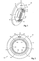
- a shift sleeve 10 which has an annular base body 12 and a total of six segments 14.
- the base body 12 is made of metal and is punched out of a metal sheet, and the segments 14 are integrally formed on the inner edge of the annular base body 12.
- the segments are alternately bent in opposite directions out of the plane of the base body 12.
- a segment extends over an angular range of about 60 ° on one side of the base body, and the circumferentially adjacent segment also extends over an angular range of about 60 °, but on the opposite side of the base body 12, and so on ,
- a toothing 16 is formed, which in the circumferential direction rotatably, but can be arranged axially displaceable on a complementary toothing of a synchronizer body. As in FIG. 2 can be seen, complement the teeth 16, although they are only partially arranged on each side of the base body 12, to a circumferentially continuous overall toothing.
- a shift fork is used, which surrounds the base body 12 in the region of the outer circumference and can adjust this in the axial direction.
- annular base body 12 further designs may be provided which are necessary for the function of the shift sleeve.
- a recess 18 is shown, which is provided at its ends facing away from each other in the circumferential direction, each with a blocking surface 20, which obliquely is aligned.
- the locking surfaces 20 may serve to cooperate with suitable locking surfaces of a friction or synchronizer ring to prevent a switching of the shift sleeve, as long as the friction or synchronizer ring must transmit a friction torque to equalize the speed of the gear wheel to the speed of the synchronizer.
- configurations may be provided, which serve for example for locking the shift sleeve in a neutral position.
- the shift sleeve shown is produced by first a sheet metal blank or an annular blank made of sheet metal is punched out. This blank contains on its inner edge the sections which are later bent to the segments.
- the gearing 16 can be made either as long as the sections are still in the plane of the blank after the sections have already been bent into cylinder segment shaped segments or after the sections have been bent into planar segment blanks.
- the toothing is preferably produced by impressing, and the segments are finally calibrated together with the teeth mounted on them.
- the gearing can be embossed or gapped by gating or depositing the teeth.
- Additional features can be applied by machining or non-cutting machining. If necessary, a heat treatment or other type of curing can be made to achieve the necessary material hardness.
Landscapes
- Engineering & Computer Science (AREA)
- General Engineering & Computer Science (AREA)
- Mechanical Engineering (AREA)
- Mechanical Operated Clutches (AREA)
Description
- Die Erfindung betrifft eine Schaltmuffe für ein Schaltgetriebe, mit einem ringförmigen Basiskörper und einer Verzahnung, die auf einer korrespondierenden Verzahnung eines Synchronkörpers verschiebbar angeordnet werden kann, wobei die Verzahnung am Innenrand des Basiskörpers ausgebildet ist, sowie ein Verfahren zur Herstellung einer solchen Schaltmuffe.
- Die Schaltmuffe bei einem Schaltgetriebe dient dazu, die drehfeste Verbindung zwischen einer Getriebewelle und einem als Losrad auf der Getriebewelle angeordneten Gangrad bei Bedarf herzustellen. Zu diesem Zweck ist die Schaltmuffe meist in axialer Richtung verschiebbar auf einem Synchronkörper so angeordnet, dass sie aus einer Ausgangsstellung in eine durchgeschaltete Stellung verschoben werden kann. In der durchgeschalteten Stellung greift die Schaltmuffe sowohl am Synchronkörper als auch einer zugeordneten Verzahnung am Gangrad an, sodass die drehfeste Verbindung hergestellt ist. Die Betätigung der Schaltmuffe erfolgt durch eine Schaltgabel, die eine Betätigung beispielsweise eines Handschalthebels in eine Verschiebung der Schaltmuffe umsetzt.
- Heute üblich sind Schaltmuffen, die entweder pulvermetallurgisch oder als Frästeile hergestellt sind. Beide Herstellungsverfahren sind relativ aufwendig.
- Die französische Offenlegungsschrift
FR 2 770 599 A1 - Aus der
DE 100 18 094 A1 ist bereits eine Schaltmuffe der eingangs genannten Art bekannt, die aus zwei Metallringen besteht, an denen eine Verzahnung angebracht ist, die aus einem Blechstreifen gebogen ist. Auch bei dieser Schaltmuffe ergibt sich ein erheblicher Aufwand bei der Fertigung, insbesondere für die Verzahnung, wenn diese mit der nötigen Präzision gefertigt werden soll. - Die Aufgabe der Erfindung besteht darin, eine Schaltmuffe für ein Schaltgetriebe zu schaffen, die sich durch einen einfachen Aufbau auszeichnet und mit geringem Aufwand hergestellt werden kann.
- Zur Lösung dieser Aufgabe ist erfindungsgemäß bei einer Schaltmuffe der eingangs genannten Art vorgesehen, dass der Basiskörper scheibenförmig ist. Die Erfindung beruht auf der Erkenntnis, dass ein voluminöser Synchronring nicht erforderlich ist. Stattdessen ist es ausreichend, einen einzigen ringförmigen Basiskörper zu verwenden, wobei unter "ringförmig" hier ein Körper zu verstehen ist, dessen Dicke sehr viel kleiner als sein Durchmesser ist. Unmittelbar an diesem Basiskörper kann die Verzahnung ausgebildet werden; es ist kein separates Bauteil nötig, das die Verzahnung bildet.
- Vorzugsweise ist vorgesehen, dass die Verzahnung an mindestens einem Segment ausgebildet ist, das vom Basiskörper nach außen abgebogen ist. Dies ermöglicht, eine Verzahnung zu schaffen, die sich in axialer Richtung über eine Länge erstreckt, die größer als die Dicke des Basiskörpers ist. Dadurch wird der Eingriff der Verzahnung mit der Verzahnung des Synchronkörpers bzw. des Gangrades verbessert.
- Vorzugsweise sind mehrere Segmente vorgesehen, die sich auf der einen und der anderen Seite des Basiskörpers erstrecken. Auf diese Weise ergibt sich eine noch größere axiale Länge der Verzahnung.
- Gemäß einer bevorzugten Ausführungsform der Erfindung sind sechs Segmente vorgesehen, die abwechselnd auf der einen und der anderen Seite des Basiskörpers angeordnet sind. Diese Anzahl von Segmenten führt zu einem guten Kompromiss zwischen Herstellungsaufwand einerseits und Herstellbarkeit andererseits.
- Vorzugsweise ist im Basiskörper mindestens eine Ausnehmung für einen Sperrmechanismus vorgesehen, der ein Durchschalten der Schaltmuffe verhindert, solange die Synchronisierung nicht abgeschlossen ist. Am Rand der Ausnehmung kann beispielsweise eine schräg angestellte Sperrfläche angeordnet sein, die eine Verdrehung eines Synchronrings solange verhindert, wie dieser ein Reibmoment zum Angleichen der Drehzahl des Gangrades an die Drehzahl der Getriebewelle übertragen muss.
- Vorzugsweise ist vorgesehen, dass der Basiskörper aus Blech besteht. Dies ermöglicht, den Basiskörper in besonders kostengünstiger und effizienter Weise durch Stanzen und Biegen in einem einzigen Bauteil herzustellen. Insbesondere sind keine Montage- oder Fügeschritte nötig.
- Erfindungsgemäß ist auch ein Verfahren zur Herstellung einer Schaltmuffe für ein Schaltgetriebe vorgesehen, das die folgenden Schritte enthält: Zunächst wird ein Basiskörper für die Schaltmuffe aus Metall bereitgestellt. Dann wird eine Verzahnung ausgebildet, die eine Öffnung im Basiskörper konzentrisch umgibt. Der Basiskörper ist scheibenförmig ausgeführt. Mit diesem Verfahren kann eine Schaltmuffe mit besonders geringem Aufwand hergestellt werden.
- Vorzugsweise ist vorgesehen, dass zunächst ein ringförmiger Rohling bereitgestellt wird, dass die Verzahnung am ebenen Rohling an mindestens einem Abschnitt ausgebildet wird und dass anschließend dieser aus der Ebene des Rohlings abgebogen wird, so dass ein Segment am Basiskörper erhalten wird. Bei dieser Vorgehensweise ist der Aufwand für das Ausbilden der Verzahnung besonders gering, da sie an einem ebenen Abschnitt vorgesehen ist.
- Gemäß einer Alternative ist vorgesehen, dass zunächst ein ringförmiger Rohling bereitgestellt wird, dass aus der Ebene des Rohlings mindestens ein Segment abgebogen wird und anschließend die Verzahnung in das Segment eingeprägt wird. Bei dieser Ausgestaltung lässt sich eine besonders hohe Qualität der Verzahnung erreichen, da das Segment nicht weiter umgeformt werden muss, nachdem die Verzahnung hergestellt ist.
- Gemäß einer weiteren Alternative ist vorgesehen, dass zunächst ein ringförmiger Rohling bereitgestellt wird, dass aus der Ebene des Rohlings mindestens ein ebener Segment-Rohling abgebogen wird, dass dann die Verzahnung in den Segment-Rohling eingeprägt wird und dass danach der Segment-Rohling in ein gekrümmtes Segment fertiggebogen wird. Diese Vorgehensweise stellt sich als guter Kompromiss zwischen den beiden vorgenannten Verfahren dar.
- Vorzugsweise wird die Verzahnung kalibriert. Auf diese Weise lässt sich die gewünschte Präzision herstellen.
- Vorzugsweise ist vorgesehen, dass der Basiskörper aus einer Metallplatte ausgestanzt wird. Dies führt zu sehr geringen Herstellungskosten im Vergleich zu einem pulvermetallurgisch oder durch Fräsen hergestellten Körper.
- Vorzugsweise ist vorgesehen, dass der Basiskörper mindestens abschnittsweise einer Wärmebehandlung unterzogen wird. Auf diese Weise kann die nötige Härte des Basiskörpers gewährleistet werden.
- Je nach den Anforderungen kann der Basiskörper abschnittsweise spanend oder auch spanlos, beispielsweise durch Prägen, Pressen oder Umformen, nachbearbeitet werden.
- Die Erfindung wird nachfolgend anhand einer Ausführungsform beschrieben, die in den beigefügten Zeichnungen dargestellt ist. In diesen zeigen:
-
Figur 1 eine perspektivische Ansicht einer erfindungsgemäßen Schaltmuffe; und -
Figur 2 eine Draufsicht auf die Schaltmuffe vonFigur 1 . - In den
Figuren 1 und 2 ist eine Schaltmuffe 10 gezeigt, die einen ringförmigen Basiskörper 12 und insgesamt sechs Segmente 14 aufweist. Der Basiskörper 12 besteht aus Metall und ist aus einem Metallblech ausgestanzt, und die Segmente 14 sind einstückig am Innenrand des ringförmigen Basiskörpers 12 ausgebildet. Dabei sind die Segmente abwechselnd in entgegengesetzten Richtungen aus der Ebene des Basiskörpers 12 abgebogen. Anders ausgedrückt: ein Segment erstreckt sich über einen Winkelbereich von etwa 60° auf der einen Seite des Basiskörpers, und das in Umfangsrichtung benachbarte Segment erstreckt sich ebenfalls über einen Winkelbereich von etwa 60°, jedoch auf der entgegengesetzten Seite des Basiskörpers 12, und so weiter. - Auf der Innenseite jedes Segments 14 ist eine Verzahnung 16 ausgebildet, die in Umfangsrichtung drehfest, jedoch axial verschiebbar auf einer komplementären Verzahnung eines Synchronkörpers angeordnet werden kann. Wie in
Figur 2 zu sehen ist, ergänzen sich die Verzahnungen 16, obwohl sie auf jeder Seite des Basiskörpers 12 nur abschnittsweise angeordnet sind, zu einer in Umfangsrichtung durchgehenden Gesamtverzahnung. - Zur axialen Verstellung der Schaltmuffe 12 wird eine Schaltgabel verwendet, die den Basiskörper 12 im Bereich des Außenumfangs umgreift und diesen in axialer Richtung verstellen kann.
- Im ringförmigen Basiskörper 12 können weitere Gestaltungen vorgesehen sein, die für die Funktion der Schaltmuffe nötig sind. Als ein Beispiel ist hier eine Ausnehmung 18 gezeigt, die an ihren in Umfangsrichtung voneinander abgewandten Enden mit jeweils einer Sperrfläche 20 versehen ist, die schräg ausgerichtet ist. Die Sperrflächen 20 können dazu dienen, mit geeigneten Sperrflächen eines Reib- oder Synchronrings zusammenzuwirken, um ein Durchschalten der Schaltmuffe zu verhindern, solange der Reib- oder Synchronring ein Reibmoment zur Angleichung der Drehzahl des Gangrades an die Drehzahl des Synchronkörpers übertragen muss. Zusätzlich können weitere, hier nicht dargestellte Gestaltungen vorgesehen sein, die beispielsweise zur Verrastung der Schaltmuffe in einer Neutralstellung dienen.
- Die gezeigte Schaltmuffe wird hergestellt, indem zunächst eine Blechronde bzw. ein ringförmiger Rohling aus Metallblech ausgestanzt wird. Dieser Rohling enthält an seinem Innenrand die Abschnitte, die später zu den Segmenten abgebogen werden. Die Verzahnung 16 kann entweder hergestellt werden, solange die Abschnitte sich noch in der Ebene des Rohlings befinden, nachdem die Abschnitte bereits zu zylinderabschnittsförmigen Segmenten umgebogen wurden oder nachdem die Abschnitte in ebene Segment-Rohlinge abgebogen wurden. Die Verzahnung wird dabei vorzugsweise durch Einprägen hergestellt, und die Segmente werden zusammen mit der an ihnen angebrachten Verzahnung abschließend kalibriert.
- Alternativ kann die Verzahnung durch Anspritzung oder Hinterlegung der Zähne geprägt und/oder zerspant herstellt werden.
- Zusätzliche Merkmale können durch spanende oder spanlose Bearbeitung angebracht werden. Soweit nötig, kann eine Wärmebehandlung oder andere Art der Härtung vorgenommen werden, um die nötige Materialhärte zu erzielen.
Claims (16)
- Schaltmuffe (10) für ein Schaltgetriebe, mit einem ringförmigen Basiskörper (12) und einer Verzahnung (16), die auf einer korrespondierenden Verzahnung eines Synchronkörpers verschiebbar angeordnet werden kann, wobei die Verzahnung am Innenrand des Basiskörpers (12) ausgebildet ist, dadurch gekennzeichnet, dass der ringförmige Basiskörper (12) scheibenförmig ist.
- Schaltmuffe nach Anspruch 1, dadurch gekennzeichnet, dass die Verzahnung an mindestens einem Segment (14) ausgebildet ist, das vom Basiskörper (12) nach außen abgebogen ist.
- Schaltmuffe nach Anspruch 2, dadurch gekennzeichnet, dass mehrere Segmente (14) vorgesehen sind, die sich auf der einen und der anderen Seite des Basiskörpers (12) erstrecken.
- Schaltmuffe nach Anspruch 3, dadurch gekennzeichnet, dass sechs Segmente (14) vorgesehen sind, die abwechselnd auf der einen und der anderen Seite des Basiskörpers (12) angeordnet sind.
- Schaltmuffe nach einem der vorhergehenden Ansprüche, dadurch gekennzeichnet, dass weitere Ausgestaltungen vorgesehen sind, die für die Verwirklichung eines Sperrmechanismus dienen.
- Schaltmuffe nach Anspruch 5, dadurch gekennzeichnet, dass im Basiskörper (12) mindestens eine Ausnehmung (18) für einen Sperrmechanismus vorgesehen ist, der ein Durchschalten der Schaltmuffe verhindert, solange die Synchronisierung nicht abgeschlossen ist.
- Schaltmuffe nach einem der vorhergehenden Ansprüche, dadurch gekennzeichnet, dass der Basiskörper (12) aus Blech besteht.
- Verfahren zur Herstellung einer Schaltmuffe (10) für ein Schaltgetriebe mit den folgenden Schritten:- es wird ein Basiskörper (12) für die Schaltmuffe (10) aus Metall bereitgestellt;- es wird eine Verzahnung (16) ausgebildet, die eine Öffnung im Basiskörper (12) konzentrisch umgibt,dadurch gekennzeichnet, dass der Basiskörper (12) scheibenförmig ist.
- Verfahren nach Anspruch 8, dadurch gekennzeichnet, dass zunächst ein ringförmiger Rohling bereitgestellt wird, dass die Verzahnung (16) am ebenen Rohling an mindestens einem Abschnitt ausgebildet wird und dass anschließend dieser aus der Ebene des Rohlings abgebogen wird, so dass ein Segment (14) am Basiskörper (12) erhalten wird.
- Verfahren nach Anspruch 8, dadurch gekennzeichnet, dass zunächst ein ringförmiger Rohling bereitgestellt wird, dass aus der Ebene des Rohlings mindestens ein Segment (14) abgebogen wird und anschließend die Verzahnung in das Segment (14) eingeprägt wird.
- Verfahren nach Anspruch 8, dadurch gekennzeichnet, dass zunächst ein ringförmiger Rohling bereitgestellt wird, dass aus der Ebene des Rohlings mindestens ein ebener Segment-Rohling abgebogen wird, dass dann die Verzahnung (16) in den Segment-Rohling eingeprägt wird und dass danach der Segment-Rohling in ein gekrümmtes Segment (14) fertiggebogen wird.
- Verfahren nach einem der Ansprüche 8 bis 11, dadurch gekennzeichnet, dass die Verzahnung (16) kalibriert wird.
- Verfahren nach einem der Ansprüche 8 bis 12, dadurch gekennzeichnet, dass der Basiskörper (12) aus einer Metallplatte ausgestanzt wird.
- Verfahren nach einem der Ansprüche 8 bis 13, dadurch gekennzeichnet, dass der Basiskörper (12) mindestens abschnittsweise einer Wärmebehandlung unterzogen wird.
- Verfahren nach einem der Ansprüche 8 bis 14, dadurch gekennzeichnet, dass der Basiskörper (12) mindestens abschnittsweise spanend nachbearbeitet wird.
- Verfahren nach einem der Ansprüche 8 bis 15, dadurch gekennzeichnet, dass der Basiskörper (12) mindestens abschnittsweise spanlos nachbearbeitet wird.
Applications Claiming Priority (2)
| Application Number | Priority Date | Filing Date | Title |
|---|---|---|---|
| DE102009041518A DE102009041518A1 (de) | 2009-09-14 | 2009-09-14 | Schaltmuffe für ein Schaltgetriebe |
| PCT/EP2010/005605 WO2011029623A1 (de) | 2009-09-14 | 2010-09-13 | Schaltmuffe für ein schaltgetriebe |
Publications (2)
| Publication Number | Publication Date |
|---|---|
| EP2478244A1 EP2478244A1 (de) | 2012-07-25 |
| EP2478244B1 true EP2478244B1 (de) | 2014-07-30 |
Family
ID=43063319
Family Applications (1)
| Application Number | Title | Priority Date | Filing Date |
|---|---|---|---|
| EP10755106.1A Not-in-force EP2478244B1 (de) | 2009-09-14 | 2010-09-13 | Schaltmuffe für ein schaltgetriebe |
Country Status (4)
| Country | Link |
|---|---|
| EP (1) | EP2478244B1 (de) |
| CN (1) | CN102575725B (de) |
| DE (1) | DE102009041518A1 (de) |
| WO (1) | WO2011029623A1 (de) |
Families Citing this family (2)
| Publication number | Priority date | Publication date | Assignee | Title |
|---|---|---|---|---|
| GB2573592B (en) * | 2018-12-19 | 2022-03-09 | Zeroshift Trans Limited | Transmission system |
| EP3708860B1 (de) | 2019-03-13 | 2021-08-04 | Ningbo Geely Automobile Research & Development Co. Ltd. | Synchronisierungsring |
Citations (1)
| Publication number | Priority date | Publication date | Assignee | Title |
|---|---|---|---|---|
| EP1447581A1 (de) * | 2003-02-07 | 2004-08-18 | Peugeot Citroen Automobiles S.A. | Synchronisiereinrichtung für ein Handschaltgetriebe. |
Family Cites Families (15)
| Publication number | Priority date | Publication date | Assignee | Title |
|---|---|---|---|---|
| DE2753342A1 (de) * | 1977-11-30 | 1979-05-31 | Helmut Droeschel | Verbesserte borg-warner-synchronisierung |
| FR2676791B1 (fr) * | 1991-05-24 | 1993-08-06 | Renault | Synchroniseur de boite de vitesses. |
| CN1098995C (zh) * | 1997-06-20 | 2003-01-15 | 日野自动车工业株式会社 | 变速装置的供油机构 |
| FR2770599B1 (fr) * | 1997-10-31 | 1999-11-26 | Peugeot | Boite de vitesses avec marche arriere synchronisee pour vehicules automobiles |
| FR2801354B1 (fr) * | 1999-11-22 | 2001-12-28 | Renault | Dispositif de synchronisation d'un pignon fou |
| DE10018094B4 (de) | 2000-04-12 | 2009-04-09 | Schaeffler Kg | Schiebemuffe einer Synchronisiereinheit für Schaltgetriebe |
| AT409234B (de) * | 2000-10-12 | 2002-06-25 | Miba Sintermetall Ag | Gesinterte schaltmuffe |
| DE10149845B4 (de) * | 2001-10-10 | 2009-01-15 | Schaeffler Kg | Grundkörper einer Schaltmuffe |
| GB0318805D0 (en) * | 2003-08-11 | 2003-09-10 | Borgwarner Inc | Segmented synchroniser clutch |
| ATE557195T1 (de) * | 2005-11-25 | 2012-05-15 | Hoerbiger & Co | Schiebemuffe |
| DE102005060572A1 (de) * | 2005-12-17 | 2007-06-21 | Volkswagen Ag | Synchronisiereinrichtung und Synchronring für eine Synchronisiereinrichtung |
| JP2007218270A (ja) * | 2006-02-14 | 2007-08-30 | Nissan Motor Co Ltd | 変速機の同期装置 |
| ATE447676T1 (de) * | 2006-09-12 | 2009-11-15 | Jen-Chih Liu | Kupplung mit vorgespannter feder für die vor-und rückwärtsbewegung |
| AT507126B1 (de) * | 2008-08-06 | 2018-05-15 | Miba Sinter Austria Gmbh | Kraftverstärkungselement |
| EP2182233B1 (de) * | 2008-10-29 | 2013-05-01 | Hoerbiger Antriebstechnik GmbH | Synchronnabe |
-
2009
- 2009-09-14 DE DE102009041518A patent/DE102009041518A1/de not_active Withdrawn
-
2010
- 2010-09-13 WO PCT/EP2010/005605 patent/WO2011029623A1/de not_active Ceased
- 2010-09-13 CN CN201080040956.4A patent/CN102575725B/zh not_active Expired - Fee Related
- 2010-09-13 EP EP10755106.1A patent/EP2478244B1/de not_active Not-in-force
Patent Citations (1)
| Publication number | Priority date | Publication date | Assignee | Title |
|---|---|---|---|---|
| EP1447581A1 (de) * | 2003-02-07 | 2004-08-18 | Peugeot Citroen Automobiles S.A. | Synchronisiereinrichtung für ein Handschaltgetriebe. |
Also Published As
| Publication number | Publication date |
|---|---|
| EP2478244A1 (de) | 2012-07-25 |
| CN102575725B (zh) | 2016-03-16 |
| CN102575725A (zh) | 2012-07-11 |
| WO2011029623A1 (de) | 2011-03-17 |
| DE102009041518A1 (de) | 2011-03-24 |
Similar Documents
| Publication | Publication Date | Title |
|---|---|---|
| EP0717212B1 (de) | Synchronisierungseinrichtung für Schaltgetriebe | |
| EP2478243B1 (de) | Übertragungsring für eine synchronisierungsbaugruppe für ein schaltgetriebe | |
| EP2677188B1 (de) | Synchronring | |
| WO2000031429A1 (de) | Anordnung und ausführung von synchronringen als spanlos geformte blechteile | |
| EP0521843B1 (de) | Reibring | |
| EP1900956A2 (de) | Getriebesynchronisierung, insbesondere in der Form einer Servo-Synchronisierung | |
| DE102010019453A1 (de) | Vorsynchroneinheit eines Schaltgetriebes | |
| WO2017041803A1 (de) | Druckstück eines fahrzeuggetriebes und synchronisiereinheit | |
| EP1175569B1 (de) | Gebauter synchronkörper mit anschlagelement | |
| DE102015102141B4 (de) | Transmitter für ein Schaltgetriebe für ein Kraftfahrzeug, Baugruppe mit Transmitter, Getriebewelle und Gangrad sowie Getriebe | |
| DE102006056487A1 (de) | Kupplungskörper mit angeformtem Konus | |
| DE102008049978A1 (de) | Schalteinheit mit Kupplungskörper | |
| WO2008028784A1 (de) | Synchronkörper | |
| DE102010036277B4 (de) | Kupplungskörper für ein Gangrad eines Schaltgetriebes sowie Gangrad mit Kupplungskörper | |
| DE102011120343B4 (de) | Verfahren zur Herstellung eines Kupplungskörpers sowie Kupplungskörper für eine Synchronisiereinrichtung | |
| EP2478244A1 (de) | Schaltmuffe für ein schaltgetriebe | |
| DE102006060535A1 (de) | Synchronisiereinrichtung für ein Schaltgetriebe | |
| DE102013215617C5 (de) | Kupplungskörper einer Synchronisiervorrichtung | |
| EP1208313B1 (de) | Synchronkörper aus einem formteil aus blech | |
| EP1966502B1 (de) | Synchronisiereinrichtung und synchronring für eine synchronisiereinrichtung | |
| DE102013221246A1 (de) | Synchronkörper | |
| EP1146243B1 (de) | Synchronisiereinheit für Schaltkupplungen | |
| DE102013101695A1 (de) | Kupplungsscheibe und Herstellungsverfahren | |
| EP3444493B1 (de) | Verfahren zur herstellung eines synchronrings und zugehöriger synchronring | |
| DE102020130712A1 (de) | Synchronring für ein Schaltgetriebe |
Legal Events
| Date | Code | Title | Description |
|---|---|---|---|
| PUAI | Public reference made under article 153(3) epc to a published international application that has entered the european phase |
Free format text: ORIGINAL CODE: 0009012 |
|
| 17P | Request for examination filed |
Effective date: 20120327 |
|
| AK | Designated contracting states |
Kind code of ref document: A1 Designated state(s): AL AT BE BG CH CY CZ DE DK EE ES FI FR GB GR HR HU IE IS IT LI LT LU LV MC MK MT NL NO PL PT RO SE SI SK SM TR |
|
| DAX | Request for extension of the european patent (deleted) | ||
| 17Q | First examination report despatched |
Effective date: 20130603 |
|
| GRAP | Despatch of communication of intention to grant a patent |
Free format text: ORIGINAL CODE: EPIDOSNIGR1 |
|
| INTG | Intention to grant announced |
Effective date: 20140213 |
|
| GRAS | Grant fee paid |
Free format text: ORIGINAL CODE: EPIDOSNIGR3 |
|
| GRAA | (expected) grant |
Free format text: ORIGINAL CODE: 0009210 |
|
| AK | Designated contracting states |
Kind code of ref document: B1 Designated state(s): AL AT BE BG CH CY CZ DE DK EE ES FI FR GB GR HR HU IE IS IT LI LT LU LV MC MK MT NL NO PL PT RO SE SI SK SM TR |
|
| REG | Reference to a national code |
Ref country code: GB Ref legal event code: FG4D Free format text: NOT ENGLISH |
|
| REG | Reference to a national code |
Ref country code: CH Ref legal event code: EP |
|
| REG | Reference to a national code |
Ref country code: AT Ref legal event code: REF Ref document number: 680141 Country of ref document: AT Kind code of ref document: T Effective date: 20140815 |
|
| REG | Reference to a national code |
Ref country code: IE Ref legal event code: FG4D Free format text: LANGUAGE OF EP DOCUMENT: GERMAN |
|
| REG | Reference to a national code |
Ref country code: DE Ref legal event code: R096 Ref document number: 502010007567 Country of ref document: DE Effective date: 20140911 |
|
| REG | Reference to a national code |
Ref country code: NL Ref legal event code: VDEP Effective date: 20140730 |
|
| REG | Reference to a national code |
Ref country code: LT Ref legal event code: MG4D |
|
| PG25 | Lapsed in a contracting state [announced via postgrant information from national office to epo] |
Ref country code: FI Free format text: LAPSE BECAUSE OF FAILURE TO SUBMIT A TRANSLATION OF THE DESCRIPTION OR TO PAY THE FEE WITHIN THE PRESCRIBED TIME-LIMIT Effective date: 20140730 Ref country code: GR Free format text: LAPSE BECAUSE OF FAILURE TO SUBMIT A TRANSLATION OF THE DESCRIPTION OR TO PAY THE FEE WITHIN THE PRESCRIBED TIME-LIMIT Effective date: 20141031 Ref country code: PT Free format text: LAPSE BECAUSE OF FAILURE TO SUBMIT A TRANSLATION OF THE DESCRIPTION OR TO PAY THE FEE WITHIN THE PRESCRIBED TIME-LIMIT Effective date: 20141202 Ref country code: ES Free format text: LAPSE BECAUSE OF FAILURE TO SUBMIT A TRANSLATION OF THE DESCRIPTION OR TO PAY THE FEE WITHIN THE PRESCRIBED TIME-LIMIT Effective date: 20140730 Ref country code: LT Free format text: LAPSE BECAUSE OF FAILURE TO SUBMIT A TRANSLATION OF THE DESCRIPTION OR TO PAY THE FEE WITHIN THE PRESCRIBED TIME-LIMIT Effective date: 20140730 Ref country code: NO Free format text: LAPSE BECAUSE OF FAILURE TO SUBMIT A TRANSLATION OF THE DESCRIPTION OR TO PAY THE FEE WITHIN THE PRESCRIBED TIME-LIMIT Effective date: 20141030 Ref country code: SE Free format text: LAPSE BECAUSE OF FAILURE TO SUBMIT A TRANSLATION OF THE DESCRIPTION OR TO PAY THE FEE WITHIN THE PRESCRIBED TIME-LIMIT Effective date: 20140730 Ref country code: BG Free format text: LAPSE BECAUSE OF FAILURE TO SUBMIT A TRANSLATION OF THE DESCRIPTION OR TO PAY THE FEE WITHIN THE PRESCRIBED TIME-LIMIT Effective date: 20141030 |
|
| PG25 | Lapsed in a contracting state [announced via postgrant information from national office to epo] |
Ref country code: PL Free format text: LAPSE BECAUSE OF FAILURE TO SUBMIT A TRANSLATION OF THE DESCRIPTION OR TO PAY THE FEE WITHIN THE PRESCRIBED TIME-LIMIT Effective date: 20140730 Ref country code: CY Free format text: LAPSE BECAUSE OF FAILURE TO SUBMIT A TRANSLATION OF THE DESCRIPTION OR TO PAY THE FEE WITHIN THE PRESCRIBED TIME-LIMIT Effective date: 20140730 Ref country code: NL Free format text: LAPSE BECAUSE OF FAILURE TO SUBMIT A TRANSLATION OF THE DESCRIPTION OR TO PAY THE FEE WITHIN THE PRESCRIBED TIME-LIMIT Effective date: 20140730 Ref country code: LV Free format text: LAPSE BECAUSE OF FAILURE TO SUBMIT A TRANSLATION OF THE DESCRIPTION OR TO PAY THE FEE WITHIN THE PRESCRIBED TIME-LIMIT Effective date: 20140730 Ref country code: IS Free format text: LAPSE BECAUSE OF FAILURE TO SUBMIT A TRANSLATION OF THE DESCRIPTION OR TO PAY THE FEE WITHIN THE PRESCRIBED TIME-LIMIT Effective date: 20141130 Ref country code: HR Free format text: LAPSE BECAUSE OF FAILURE TO SUBMIT A TRANSLATION OF THE DESCRIPTION OR TO PAY THE FEE WITHIN THE PRESCRIBED TIME-LIMIT Effective date: 20140730 |
|
| PG25 | Lapsed in a contracting state [announced via postgrant information from national office to epo] |
Ref country code: DK Free format text: LAPSE BECAUSE OF FAILURE TO SUBMIT A TRANSLATION OF THE DESCRIPTION OR TO PAY THE FEE WITHIN THE PRESCRIBED TIME-LIMIT Effective date: 20140730 Ref country code: CZ Free format text: LAPSE BECAUSE OF FAILURE TO SUBMIT A TRANSLATION OF THE DESCRIPTION OR TO PAY THE FEE WITHIN THE PRESCRIBED TIME-LIMIT Effective date: 20140730 Ref country code: RO Free format text: LAPSE BECAUSE OF FAILURE TO SUBMIT A TRANSLATION OF THE DESCRIPTION OR TO PAY THE FEE WITHIN THE PRESCRIBED TIME-LIMIT Effective date: 20140730 Ref country code: EE Free format text: LAPSE BECAUSE OF FAILURE TO SUBMIT A TRANSLATION OF THE DESCRIPTION OR TO PAY THE FEE WITHIN THE PRESCRIBED TIME-LIMIT Effective date: 20140730 Ref country code: LU Free format text: LAPSE BECAUSE OF FAILURE TO SUBMIT A TRANSLATION OF THE DESCRIPTION OR TO PAY THE FEE WITHIN THE PRESCRIBED TIME-LIMIT Effective date: 20140913 Ref country code: SK Free format text: LAPSE BECAUSE OF FAILURE TO SUBMIT A TRANSLATION OF THE DESCRIPTION OR TO PAY THE FEE WITHIN THE PRESCRIBED TIME-LIMIT Effective date: 20140730 Ref country code: IT Free format text: LAPSE BECAUSE OF FAILURE TO SUBMIT A TRANSLATION OF THE DESCRIPTION OR TO PAY THE FEE WITHIN THE PRESCRIBED TIME-LIMIT Effective date: 20140730 Ref country code: MC Free format text: LAPSE BECAUSE OF FAILURE TO SUBMIT A TRANSLATION OF THE DESCRIPTION OR TO PAY THE FEE WITHIN THE PRESCRIBED TIME-LIMIT Effective date: 20140730 |
|
| REG | Reference to a national code |
Ref country code: CH Ref legal event code: PL |
|
| REG | Reference to a national code |
Ref country code: DE Ref legal event code: R097 Ref document number: 502010007567 Country of ref document: DE |
|
| PLBE | No opposition filed within time limit |
Free format text: ORIGINAL CODE: 0009261 |
|
| STAA | Information on the status of an ep patent application or granted ep patent |
Free format text: STATUS: NO OPPOSITION FILED WITHIN TIME LIMIT |
|
| REG | Reference to a national code |
Ref country code: IE Ref legal event code: MM4A |
|
| GBPC | Gb: european patent ceased through non-payment of renewal fee |
Effective date: 20141030 |
|
| PG25 | Lapsed in a contracting state [announced via postgrant information from national office to epo] |
Ref country code: BE Free format text: LAPSE BECAUSE OF NON-PAYMENT OF DUE FEES Effective date: 20140930 |
|
| 26N | No opposition filed |
Effective date: 20150504 |
|
| PG25 | Lapsed in a contracting state [announced via postgrant information from national office to epo] |
Ref country code: GB Free format text: LAPSE BECAUSE OF NON-PAYMENT OF DUE FEES Effective date: 20141030 Ref country code: LI Free format text: LAPSE BECAUSE OF NON-PAYMENT OF DUE FEES Effective date: 20140930 Ref country code: CH Free format text: LAPSE BECAUSE OF NON-PAYMENT OF DUE FEES Effective date: 20140930 |
|
| PG25 | Lapsed in a contracting state [announced via postgrant information from national office to epo] |
Ref country code: IE Free format text: LAPSE BECAUSE OF NON-PAYMENT OF DUE FEES Effective date: 20140913 |
|
| REG | Reference to a national code |
Ref country code: FR Ref legal event code: PLFP Year of fee payment: 6 |
|
| PG25 | Lapsed in a contracting state [announced via postgrant information from national office to epo] |
Ref country code: SI Free format text: LAPSE BECAUSE OF FAILURE TO SUBMIT A TRANSLATION OF THE DESCRIPTION OR TO PAY THE FEE WITHIN THE PRESCRIBED TIME-LIMIT Effective date: 20140730 |
|
| PG25 | Lapsed in a contracting state [announced via postgrant information from national office to epo] |
Ref country code: SM Free format text: LAPSE BECAUSE OF FAILURE TO SUBMIT A TRANSLATION OF THE DESCRIPTION OR TO PAY THE FEE WITHIN THE PRESCRIBED TIME-LIMIT Effective date: 20140730 |
|
| PG25 | Lapsed in a contracting state [announced via postgrant information from national office to epo] |
Ref country code: MT Free format text: LAPSE BECAUSE OF FAILURE TO SUBMIT A TRANSLATION OF THE DESCRIPTION OR TO PAY THE FEE WITHIN THE PRESCRIBED TIME-LIMIT Effective date: 20140730 |
|
| PG25 | Lapsed in a contracting state [announced via postgrant information from national office to epo] |
Ref country code: HU Free format text: LAPSE BECAUSE OF FAILURE TO SUBMIT A TRANSLATION OF THE DESCRIPTION OR TO PAY THE FEE WITHIN THE PRESCRIBED TIME-LIMIT; INVALID AB INITIO Effective date: 20100913 Ref country code: TR Free format text: LAPSE BECAUSE OF FAILURE TO SUBMIT A TRANSLATION OF THE DESCRIPTION OR TO PAY THE FEE WITHIN THE PRESCRIBED TIME-LIMIT Effective date: 20140730 |
|
| REG | Reference to a national code |
Ref country code: FR Ref legal event code: PLFP Year of fee payment: 7 |
|
| REG | Reference to a national code |
Ref country code: AT Ref legal event code: MM01 Ref document number: 680141 Country of ref document: AT Kind code of ref document: T Effective date: 20150913 |
|
| PG25 | Lapsed in a contracting state [announced via postgrant information from national office to epo] |
Ref country code: AT Free format text: LAPSE BECAUSE OF NON-PAYMENT OF DUE FEES Effective date: 20150913 |
|
| REG | Reference to a national code |
Ref country code: FR Ref legal event code: PLFP Year of fee payment: 8 |
|
| PG25 | Lapsed in a contracting state [announced via postgrant information from national office to epo] |
Ref country code: MK Free format text: LAPSE BECAUSE OF FAILURE TO SUBMIT A TRANSLATION OF THE DESCRIPTION OR TO PAY THE FEE WITHIN THE PRESCRIBED TIME-LIMIT Effective date: 20140730 |
|
| REG | Reference to a national code |
Ref country code: FR Ref legal event code: PLFP Year of fee payment: 9 |
|
| PG25 | Lapsed in a contracting state [announced via postgrant information from national office to epo] |
Ref country code: AL Free format text: LAPSE BECAUSE OF FAILURE TO SUBMIT A TRANSLATION OF THE DESCRIPTION OR TO PAY THE FEE WITHIN THE PRESCRIBED TIME-LIMIT Effective date: 20140730 |
|
| PGFP | Annual fee paid to national office [announced via postgrant information from national office to epo] |
Ref country code: FR Payment date: 20180928 Year of fee payment: 9 |
|
| PGFP | Annual fee paid to national office [announced via postgrant information from national office to epo] |
Ref country code: DE Payment date: 20181130 Year of fee payment: 9 |
|
| REG | Reference to a national code |
Ref country code: DE Ref legal event code: R119 Ref document number: 502010007567 Country of ref document: DE |
|
| PG25 | Lapsed in a contracting state [announced via postgrant information from national office to epo] |
Ref country code: DE Free format text: LAPSE BECAUSE OF NON-PAYMENT OF DUE FEES Effective date: 20200401 |
|
| PG25 | Lapsed in a contracting state [announced via postgrant information from national office to epo] |
Ref country code: FR Free format text: LAPSE BECAUSE OF NON-PAYMENT OF DUE FEES Effective date: 20190930 |