EP2476929B2 - Nachstellvorrichtung für eine Scheibenbremse - Google Patents
Nachstellvorrichtung für eine Scheibenbremse Download PDFInfo
- Publication number
- EP2476929B2 EP2476929B2 EP10016215.5A EP10016215A EP2476929B2 EP 2476929 B2 EP2476929 B2 EP 2476929B2 EP 10016215 A EP10016215 A EP 10016215A EP 2476929 B2 EP2476929 B2 EP 2476929B2
- Authority
- EP
- European Patent Office
- Prior art keywords
- readjustment
- brake
- disc
- friction
- friction element
- Prior art date
- Legal status (The legal status is an assumption and is not a legal conclusion. Google has not performed a legal analysis and makes no representation as to the accuracy of the status listed.)
- Active
Links
Images
Classifications
-
- F—MECHANICAL ENGINEERING; LIGHTING; HEATING; WEAPONS; BLASTING
- F16—ENGINEERING ELEMENTS AND UNITS; GENERAL MEASURES FOR PRODUCING AND MAINTAINING EFFECTIVE FUNCTIONING OF MACHINES OR INSTALLATIONS; THERMAL INSULATION IN GENERAL
- F16D—COUPLINGS FOR TRANSMITTING ROTATION; CLUTCHES; BRAKES
- F16D65/00—Parts or details
- F16D65/38—Slack adjusters
- F16D65/40—Slack adjusters mechanical
- F16D65/52—Slack adjusters mechanical self-acting in one direction for adjusting excessive play
- F16D65/56—Slack adjusters mechanical self-acting in one direction for adjusting excessive play with screw-thread and nut
- F16D65/567—Slack adjusters mechanical self-acting in one direction for adjusting excessive play with screw-thread and nut for mounting on a disc brake
-
- F—MECHANICAL ENGINEERING; LIGHTING; HEATING; WEAPONS; BLASTING
- F16—ENGINEERING ELEMENTS AND UNITS; GENERAL MEASURES FOR PRODUCING AND MAINTAINING EFFECTIVE FUNCTIONING OF MACHINES OR INSTALLATIONS; THERMAL INSULATION IN GENERAL
- F16D—COUPLINGS FOR TRANSMITTING ROTATION; CLUTCHES; BRAKES
- F16D65/00—Parts or details
- F16D65/14—Actuating mechanisms for brakes; Means for initiating operation at a predetermined position
- F16D65/16—Actuating mechanisms for brakes; Means for initiating operation at a predetermined position arranged in or on the brake
- F16D65/18—Actuating mechanisms for brakes; Means for initiating operation at a predetermined position arranged in or on the brake adapted for drawing members together, e.g. for disc brakes
-
- F—MECHANICAL ENGINEERING; LIGHTING; HEATING; WEAPONS; BLASTING
- F16—ENGINEERING ELEMENTS AND UNITS; GENERAL MEASURES FOR PRODUCING AND MAINTAINING EFFECTIVE FUNCTIONING OF MACHINES OR INSTALLATIONS; THERMAL INSULATION IN GENERAL
- F16D—COUPLINGS FOR TRANSMITTING ROTATION; CLUTCHES; BRAKES
- F16D2121/00—Type of actuator operation force
- F16D2121/14—Mechanical
-
- F—MECHANICAL ENGINEERING; LIGHTING; HEATING; WEAPONS; BLASTING
- F16—ENGINEERING ELEMENTS AND UNITS; GENERAL MEASURES FOR PRODUCING AND MAINTAINING EFFECTIVE FUNCTIONING OF MACHINES OR INSTALLATIONS; THERMAL INSULATION IN GENERAL
- F16D—COUPLINGS FOR TRANSMITTING ROTATION; CLUTCHES; BRAKES
- F16D2125/00—Components of actuators
- F16D2125/18—Mechanical mechanisms
- F16D2125/20—Mechanical mechanisms converting rotation to linear movement or vice versa
- F16D2125/22—Mechanical mechanisms converting rotation to linear movement or vice versa acting transversely to the axis of rotation
- F16D2125/26—Cranks
-
- F—MECHANICAL ENGINEERING; LIGHTING; HEATING; WEAPONS; BLASTING
- F16—ENGINEERING ELEMENTS AND UNITS; GENERAL MEASURES FOR PRODUCING AND MAINTAINING EFFECTIVE FUNCTIONING OF MACHINES OR INSTALLATIONS; THERMAL INSULATION IN GENERAL
- F16D—COUPLINGS FOR TRANSMITTING ROTATION; CLUTCHES; BRAKES
- F16D2125/00—Components of actuators
- F16D2125/18—Mechanical mechanisms
- F16D2125/20—Mechanical mechanisms converting rotation to linear movement or vice versa
- F16D2125/22—Mechanical mechanisms converting rotation to linear movement or vice versa acting transversely to the axis of rotation
- F16D2125/28—Cams; Levers with cams
- F16D2125/32—Cams; Levers with cams acting on one cam follower
-
- F—MECHANICAL ENGINEERING; LIGHTING; HEATING; WEAPONS; BLASTING
- F16—ENGINEERING ELEMENTS AND UNITS; GENERAL MEASURES FOR PRODUCING AND MAINTAINING EFFECTIVE FUNCTIONING OF MACHINES OR INSTALLATIONS; THERMAL INSULATION IN GENERAL
- F16D—COUPLINGS FOR TRANSMITTING ROTATION; CLUTCHES; BRAKES
- F16D2125/00—Components of actuators
- F16D2125/18—Mechanical mechanisms
- F16D2125/58—Mechanical mechanisms transmitting linear movement
- F16D2125/64—Levers
Definitions
- the invention relates to an adjusting device for a disc brake, in particular for commercial vehicles, with an adjusting element in the form of an adjusting nut and a slip clutch for limiting the transmitted torque to the adjusting element.
- Adjusting devices of the type mentioned are known, for example from the EP 0 730 170 B1 ,
- the slip clutch is formed by a Reibkonus on a driven sleeve on the one hand and on the other hand by a pressure sleeve.
- determining force on the output sleeve serve a retaining ring on which a compression spring is supported, and a support plate on which the compression spring exerts an elastic force.
- the serving as a torque limiting friction cone is under the bias of the compression spring on an annular Edge of the pressure sleeve on. This construction may be subject to wear.
- the only spring-loaded support disk is susceptible to vibration.
- the invention has the object of developing the adjuster of the type mentioned above such that it is more flexible and thus can be designed so that greater wear resistance and reliability are achieved.
- the slip clutch is no longer formed only with the inclusion of serving as an adjusting element in the form of an adjusting pressure sleeve. Rather, a separate friction element is introduced, which is rotationally coupled with the adjusting element in both directions. This separate friction element makes the overall construction more flexible. It can thus be a solution with less susceptibility to wear and increased reliability can be realized.
- the sliding clutch includes, on the one hand, a contact surface on the adjusting element and a friction surface, for example on an output element / output sleeve of the adjuster and, on the other hand, the separate additional friction element.
- Characterized the torque to be transmitted is transmitted over two paths through the Ruschkupplung, namely on the one hand over the contact surface on the adjusting element and the friction surface, and on the other via the friction element which is coupled to the adjusting element in both directions of rotation.
- the slip clutch two partial clutches which are functionally connected in parallel. It can be achieved greater wear resistance and greater reliability.
- the DE 43 23 292 A1 shows an adjusting device for a disc brake with a slip clutch.
- To the slip clutch includes a ring with a spur gear, which is rotatably and axially non-displaceable connected to a belonging to the adjusting device shaft.
- a friction surface of the friction element forming part of the slip clutch preferably faces a brake disk in the installed state.
- the friction surface is "inside", making the overall structure more compact.
- the friction element according to the invention further preferably has a coupling device for coupling with an adjusting device for the adjusting element.
- This coupling device offers the possibility of adjustment, which after the EP 0 730 107 B1 is formed on the pressure sleeve itself, take away from the pressure sleeve, for example, to settle next to it, whereby the overall length in the axial direction of the adjusting device can be reduced.
- the coupling device according to the invention preferably on a sprocket. This solution is preferred as mechanically particularly easy to implement.
- the coupling device has a deviating from the circular inner contour of the friction element, for example in the form of an internal gear, and / or a profiling on the side facing away from the brake disc of the friction element.
- the friction element itself represents the adjusting device, in which, for example, for adjusting a tool matched to the inner contour can be inserted.
- a profiling of the adjusting element can be provided for coupling with an adjusting tool.
- the adjusting element is provided for example on its side facing away from the brake disc with a recess into which fits a Inbus nowadaysi.
- a hexagon socket, an external hexagon, a slot for a screwdriver or the like may also be provided.
- the tool can be reset each time to adjust. But it can also be provided that at least a part of the tool is permanently coupled via the profiling with the adjusting element.
- a biasing device is preferably provided for biasing the slip clutch in the sense of a frictional engagement.
- the applied by the biasing biasing force thereby determines the maximum transmissible by the slip clutch torque
- the biasing device according to the invention more preferably an elastic device on the side facing away from the brake disc in the installed state of the friction element.
- the biasing direction is on the "outside” of the friction element. As a result, it does not take up any space required for other components on the "inside” of the friction element.
- the biasing means comprises, according to a particularly preferred embodiment of the invention, one, two or more disc spring (s).
- This embodiment in turn offers the advantage of small installation space in the axial direction.
- a part of the friction clutch forming friction surface according to the invention is further preferably annular.
- a friction surface forming part of the slip clutch is preferably at least partially flat, conical-shell-shaped or toothed.
- the concrete design of the friction surface is to be turned off on the overall circumstances. Thus, for example, if a larger friction surface is required, the conical-frustum friction surface will be the best solution. Large marginal moments can be achieved with a toothed friction surface.
- the invention also provides a disc brake, in particular for commercial vehicles, with such an adjusting device.
- At least parts of the adjusting device are coupled to a pressure piece in such a way that they follow their movement in the axial direction of the brake when tightening.
- the pressure piece according to the invention preferably has a rectangular contour, wherein it has in particular a truss structure.
- an adjusting device is provided, the axis of rotation does not coincide with the axis of rotation of the slip clutch.
- the adjusting device is arranged, as it were, "next to the slip clutch.”
- This embodiment can serve to shorten the installation space of the brake in the axial direction.
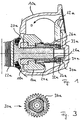
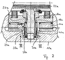
- FIGS. 1 to 3 is a disc brake shown. It has a caliper 10a. Furthermore, it has an application device to which a rotary lever 12a with a brake shaft 14a belongs. If the rotary lever is pivoted in the direction "D", it exerts pressure on a pressure piece 16a, which forms a traverse of the brake. The pressure piece 16a in turn presses on a pressure sleeve 18a, which then transmits the clamping force via a pressure screw 20a on a brake pad 22a. Therefore, upon actuation of the rotary lever 12a, the brake pad 22a is pressed against a brake disc, not shown in the drawing.
- a drive sleeve 24a is coupled to the brake shaft 14a such that a pivoting of the rotary lever 12a after overcoming a clearance leads to a rotation of the drive sleeve 24a.
- the longitudinal axis of the pin 23a is inclined relative to the axis of rotation of the brake shaft 14a, for example by 18 °. Because of the improved translation achieved thereby, a higher degree of adjustment per actuation of the brake is achieved.
- the drive sleeve 24a is coupled to a driven sleeve 28a via a wrap spring 26a serving as a one-way clutch. As a result, the output sleeve 28a also rotates when tightening.
- the output sleeve 28a forms together with a support plate 30a a slip clutch.
- the support disk 30a rests against the output sleeve 28a with its friction surface 32a facing "inwards”.
- the output sleeve 28a in turn lies in this embodiment with a friction surface 40a (here flat) on a contact surface 38a of the pressure sleeve 18a.
- For bias serve three disc springs 33a, which are supported on a locking ring 34a.
- the support disk 30a has according to FIG. 3 an outer contour deviating from the circular shape, in the illustrated embodiment, approximately star-shaped, wherein the outer contour of the pressure sleeve 18a where the support disk 30a sits, a complementary outer contour, so that the support plate 30a is rotationally coupled to the pressure sleeve 18a in both directions of rotation.
- each other causes a pivoting of the brake lever 12a in the direction of "D" after overcoming the clearance rotation of the pressure sleeve 18a, which is screwed to the rotatably held pressure screw 20a, so that the pressure screw 20a in FIG 5 unscrewed to the left from the pressure sleeve 18a.
- the support disk 30a is according to FIG. 3 provided on its outer edge with a ring gear 36a.
- the ring gear 36a engages in the installed state in an adjustment shaft, not shown in the drawing.
- the Justierwelle is so to speak "next to" the actual adjustment, which has the advantage of lower axial length.
- the adjusting shaft may for example have a hexagonal head.
- a work opening also not shown in the drawing, is provided on the saddle 10a. The work opening can be closed with a stopper to protect against contamination.
- the adjusting shaft serves, for example, to rotate the support disk 30a and the thrust-coupled pressure sleeve 18a in order to screw the pressure screw 20a back into the pressure sleeve 18a, for example after renewal of the brake lining 22a.
- the support plate 30a itself serve as an adjustment.
- it may have on the side facing away from the brake disc a deviating from the circular shape inner contour and / or a profiling, in which a corresponding tool is to be inserted for adjusting.
- a corresponding working opening will be provided on the saddle 10a, again closed with a plug. It can also be provided to attach an adjusting tool directly to the pressure sleeve 18a.
- the support plate 30a of the coupling of the clamping causing the rotary lever 12a with the adjusting device because it sits rotationally fixed on the pressure sleeve 18a and therefore can transmit torques.
- the invention also covers solutions without such an adjusting shaft in addition to the actual adjusting device.
- the support plate 30a have a deviating from the circular shape inner contour, so that an adjustment of the adjusting device can be made directly to the support plate 30a by applying a corresponding tool.
- the invention is applicable to brakes with one, two or more compression screw (s) / - spindle (s) and brakes with and without pressure piece.
Landscapes
- Engineering & Computer Science (AREA)
- General Engineering & Computer Science (AREA)
- Mechanical Engineering (AREA)
- Braking Arrangements (AREA)
Description
- Die Erfindung betrifft eine Nachstellvorrichtung für eine Scheibenbremse, insbesondere für Nutzfahrzeuge, mit
einem Nachstellelement in Form einer Nachstellmutter und
einer Rutschkupplung zum Begrenzen des auf das Nachstellelement übertragenen Drehmoments. - Nachstellvorrichtungen der eingangs genannten Art sind bekannt, beispielsweise aus der
EP 0 730 170 B1 . Dabei wird die Rutschkupplung von einem Reibkonus an einer Abtriebshülse einerseits und von einer Druckhülse andererseits gebildet. Zum Aufbringen einer das Grenzmoment der Rutschkupplung bestimmenden Kraft auf die Abtriebshülse dienen ein Haltering, an dem sich eine Druckfeder abstützt, sowie eine Stützscheibe, auf die die Druckfeder eine elastische Kraft ausübt. Der als Drehmomentbegrenzungsbereich dienende Reibkonus liegt unter der Vorspannung der Druckfeder an einer ringförmigen Kante der Druckhülse an. Diese Konstruktion kann Verschleiß unterliegen. Ferner ist die nur federgehaltene Stützscheibe schwingungsanfällig. - Der Erfindung liegt die Aufgabe zugrunde, die Nachstellvorrichtung der oben genannten Art derart weiterzubilden, daß sie flexibler ist und mithin derart gestaltet werden kann, daß größere Verschleißfestigkeit und Funktionssicherheit erzielt werden.
- Erfindungsgemäß wird die gestellte Aufgabe durch eine Nachstellvorrichtung nach Anspruch 1 gelöst.
- Mit anderen Worten wird die Rutschkupplung nicht mehr nur unter Einbeziehung der als Nachstellelement in Form einer Nachstellmutter dienenden Druckhülse gebildet. Vielmehr wird ein separates Reibelement eingeführt, das mit dem Nachstellelement in beiden Richtungen drehgekoppelt ist. Durch dieses separate Reibelement wird die Gesamtkonstruktion flexibler. Es kann damit auch eine Lösung mit geringerer Verschleißanfälligkeit und erhöhter Funktionssicherheit verwirklicht werden.
- Zu der Rutschkupplung gehören also erfindungsgemäß einerseits eine Anlagefläche an dem Nachstellelement und eine Reibfläche, beispielsweise an einem Abtriebselement / einer Abtriebshülse des Nachstellers und andererseits das separate zusätzliche Reibelement. Dadurch wird das zu übertragende Moment über zwei Wege durch die Ruschkupplung übertragen, nämlich zum einen über die Anlagefläche an dem Nachstellelement und die Reibfläche, und zum anderen über das Reibelement, das mit dem Nachstellelement in beiden Drehrichtungen gekoppelt ist. Mit anderen Worten gehören erfindungsgemäß zu der Rutschkupplung zwei Teilkupplungen, die funktionsmäßig parallel geschaltet sind. Es kann größere Verschleißfestigkeit und größere Funktionssicherheit erzielt werden.
- Die
DE 43 23 292 A1 zeigt eine Nachstellvorrichtung für eine Scheibenbremse mit einer Rutschkupplung. Zu der Rutschkupplung gehört ein Ring mit einer Stirnverzahnung, der drehfest und axial nicht verschiebbar mit einer zu der Nachstellvorrichtung gehörenden Profilwelle verbunden ist. - Erfindungsgemäß bevorzugt ist eine einen Teil der Rutschkupplung bildende Reibfläche des Reibelements in eingebautem Zustand einer Bremsscheibe zugewandt.
- Mitanderen Worten liegt die Reibfläche "innen", wodurch der Gesamtaufbau kompakter wird.
- Das Reibelement weist erfindungsgemäß weiter bevorzugt eine Kuppeleinrichtung zum Koppeln mit einer Justiereinrichtung für das Nachstellelement auf.
- Diese Kuppeleinrichtung bietet die Möglichkeit, die Justiereinrichtung, die nach der
EP 0 730 107 B1 an der Druckhülse selbst ausgebildet ist, von der Druckhülse wegzunehmen, beispielsweise daneben anzusiedeln, wodurch die Baulänge in Axialrichtung der Nachstellvorrichtung verringert werden kann. - Zu diesem Zwecke weist die Kuppeleinrichtung erfindungsgemäß bevorzugt einen Zahnkranz auf. Diese Lösung wird als mechanisch besonders einfach zu realisieren bevorzugt.
- Zusätzlich oder alternativ kann vorgesehen sein, daß die Kuppeleinrichtung eine von der Kreisform abweichende Innenkontur an dem Reibelement, beispielsweise in Form eines Innenzahnkranzes, und/oder eine Profilierung auf der der Bremsscheibe abgewandten Seite des Reibelements aufweist. Nach dieser Ausgestaltung stellt das Reibelement selbst die Justiereinrichtung dar, in die beispielsweise zum Justieren ein der Innenkontur angepaßtes Werkzeug eingesteckt werden kann.
- Ferner kann zusätzlich oder alternativ eine Profilierung des Nachstellelements zum Koppeln mit einem Justierwerkzeug vorgesehen sein.
- Bei dieser Ausgestaltung ist das Nachstellelement beispielsweise auf seiner der Bremsscheibe abgewandten Seite mit einer Ausnehmung versehen, in die ein Inbusschlüssei paßt. Mit dem Inbusschlüssel kann eine Justierung vorgenommen werden, beispielsweise nach Erneuerung eines Bremsbelages. Anstelle derAusnehmung für einen Inbusschlüssei kann auch ein Innensechskant, ein Außensechskant, ein Schlitz für einen Schraubendreher oder dergleichen vorgesehen sein. Das Werkzeug kann dabei jedes Mal zum Justieren wieder anzusetzen sein. Es kann aber auch vorgesehen sein, daß zumindest ein Teil des Werkzeugs dauerhaft über die Profilierung mit dem Nachstellelement gekoppelt ist.
- Erfindungsgemäß weiter bevorzugt ist eine Vorspanneinrichtung zum Vorspannen der Rutschkupplung im Sinne eines Reibschlusses vorgesehen.
- Die von der Vorspanneinrichtung aufgebrachte Vorspannkraft bestimmt dadurch das maximal von der Rutschkupplung übertragbare Drehmoment
- Die Vorspanneinrichtung weist erfindungsgemäß weiter bevorzugt eine elastische Einrichtung auf der einer Bremsscheibe in eingebautem Zustand abgewandten Seite des Reibelements auf.
- Mit anderen Worten liegt die Vorspannrichtung auf der "Außenseite" des Reibelements. Dadurch nimmt sie auf der "Innenseite" des Reibelements keinen für andere Bauteile benötigten Bauraum ein.
- Die Vorspanneinrichtung weist nach einer besonders bevorzugten Ausführungsform der Erfindung eine, zwei oder mehr Tellerfeder(n) auf.
- Diese Ausgestaltung bietet wiederum den Vorteil des geringen Bauraums in Axialrichtung.
- Eine einen Teil der Rutschkupplung bildende Reibfläche ist erfindungsgemäß weiter bevorzugt ringförmig.
- Dabei ist weiter bevorzugt eine einen Teil der Rutschkupplung bildende Reibfläche zumindest zum Teil eben, kegelschnittmantelförmig oder verzahnt.
- Die konkrete Ausgestaltung der Reibfläche ist auf die Gesamtumstände abzustellen. So kann beispielsweise dann, wenn eine größere Reibfläche erforderlich ist, die kegelschnittmantefförmige Reibfläche die beste Lösung sein. Große Grenzmomente sind mit einer verzahnten Reibfläche erzielbar.
- Neben der oben im einzelnen beschriebenen Nachstellvorrichtung schafft die Erfindung auch eine Scheibenbremse, insbesondere für Nutzfahrzeuge, mit einer solchen Nachstellvorrichtung.
- Bevorzugt sind zumindest Teile der Nachstellvorrichtung derart mit einem Druckstück gekoppelt, daß sie beim Zuspannen dessen Bewegung in Axialrichtung der Bremse folgen.
- Während auch Teile der Nachstellvorrichtung mit einem Sattel der Scheibenbremse gekoppelt sein können, bietet eine komplette Kopplung mit dem Druckstück den Vorteil, daß Sattelschwingungen nicht zu Fehlstellungen führen können.
- Das Druckstück weist erfindungsgemäß bevorzugt eine rechteckige Kontur auf, wobei es insbesondere eine Traversenstruktur hat.
- Nach einer besonders bevorzugten Ausführungsform der Erfindung ist eine Justiereinrichtung vorgesehen, deren Drehachse nicht mit der Drehachse der Rutschkupplung zusammenfällt.
- Mit anderen Worten ist die Justiereinrichtung quasi ,neben" der Rutschkupplung angeordnet. Diese Ausgestaltung kann dazu dienen, den Bauraum der Bremse in Axialrichtung zu verkürzen.
- Im folgenden ist die Erfindung anhand eines bevorzugten Ausführungsbeispiels unter Bezugnahme auf die beiliegende Zeichnung mit weiteren Einzelheiten näher erläutert. Dabei zeigen
- Figur 1
- eine Schnittansicht einer Nutzfahrzeug-Scheibenbremse nach einem bevorzugten Ausführungsbeispiel der Erfindung,
- Figur 2
- eine andere Schnittansicht der erfindungsgemäßen Bremse, mit weiteren Einzelheiten und
- Figur 3
- eine Axialansicht eines Reibelements der Bremse nach
Figur 1 . - In den
Figuren 1 bis 3 ist eine Scheibenbremse dargestellt. Sie weist einen Bremssattel 10a auf. Ferner weist sie eine Zuspanneinrichtung auf, zu der ein Drehhebel 12a mit einer Bremswelle 14a gehört. Wird der Drehhebel in Richtung "D" verschwenkt, so übt er Druck auf ein Druckstück 16a aus, das eine Traverse der Bremse bildet. Das Druckstück 16a seinerseits drückt auf eine Druckhülse 18a, die die Zuspannkraft dann über eine Druckschraube 20a auf einen Bremsbelag 22a überträgt. Daherwird bei Betätigen des Drehhebels 12a der Bremsbelag 22a gegen eine in der Zeichnung nicht dargestellte Bremsscheibe gedrückt. - Durch einen Stift 23a ist eine Antriebshülse 24a mit der Bremswelle 14a derart gekoppelt, daß ein Verschwenken des Drehhebels 12a nach Überwindung eines Lüftspiels zu einem Verdrehen der Antriebshülse 24a führt. Die Längsachse des Stiftes 23a ist bezüglich der Drehachse der Bremswelle 14a schräg angestellt, beispielsweise um 18°. Wegen der dadurch erzielten verbesserten Übersetzung wird ein höheres Maß an Nachstellung pro Betätigung der Bremse erzielt. Die Antriebshülse 24a ist über eine als Einwegkupplung dienende Schlingfeder 26a mit einer Abtriebshülse 28a gekoppelt. Dadurch dreht sich beim Zuspannen auch die Abtriebshülse 28a. Die Abtriebshülse 28a bildet zusammen mit einer Stützscheibe 30a eine Rutschkupplung. Dazu liegt die Stützscheibe 30a mit ihrer nach "innen" weisenden Reibfläche 32a an der Abtriebshülse 28a an. Die Abtriebshülse 28a ihrerseits liegt bei diesem Ausführungsbeispiel mit einer Reibfläche 40a (hier eben) an einer Anlagefläche 38a der Druckhülse 18a an. Zur Vorspannung dienen drei Tellerfedern 33a, die sich an einem Sicherungsring 34a abstützen.
- Die Stützscheibe 30a hat gemäß
Figur 3 eine von der Kreisform abweichende Innenkontur, im gezeigten Ausführungsbeispiel etwa sternförmig, wobei die Außenkontur der Druckhülse 18a dort, wo die Stützscheibe 30a sitzt, eine komplementäre Außenkontur hat, so daß die Stützscheibe 30a mit der Druckhülse 18a in beiden Drehrichtungen drehgekoppelt ist. - Wegen der oben im einzelnen beschriebenen Kopplungen der einzelnen Bauteile miteinander bewirkt ein Verschwenken des Bremshebels 12a in Richtung "D" nach Überwinden des Lüftspiels ein Verdrehen der Druckhülse 18a, die mit der drehfest gehaltenen Druckschraube 20a verschraubt ist, so daß sich die Druckschraube 20a in Figur 5 nach links aus der Druckhülse 18a herausschraubt.
- Dieses Herausschrauben erfolgt aber nur, bis der Bremsbelag 22a an der Bremsscheibe anliegt. Wird dann nämlich weiter zugespannt, steigt die Reibung zwischen dem Druckstück 16a und der Druckhülse 18a, so daß sich die Druckhülse 18a nicht mehrweiter verdrehen kann. In ähnlicher Weise wirkt das mit zunehmendem Druck auftretende Reibmoment innerhalb der Schraubverbindung zwischen der Druckhülse 18a und der Druckschraube 20a.
- Daher rutscht bei weiterem Verschwenken des Drehhebels 12a in Richtung "D" die Abtriebshülse 28a bezüglich der Stützscheibe 30a und der Druckhülse 18a durch. Ein weiteres Herausschrauben der Druckschraube 20a aus der Druckhülse 18a erfolgt also nicht mehr.
- Die oben im einzelnen beschriebene Konstruktion wird in der Fachsprache als kraft-, last- oder drehmomentabhängige Nachstellung bezeichnet, weil eine Nachstellung entsprechend den obigen Erläuterungen nur erfolgt, bis die Kraft, die Last bzw. das Drehmoment einen entsprechend der Ausgestaltung des Reibschlusses zwischen der Abtriebshülse 28a einerseits und der Stützscheibe 30a sowie der Druckhülse 18a andererseits übertragbaren Wert übersteigt. Dieser Wert kann insbesondere durch entsprechende Dimensionierung der Tellerfedern 33a vorgegeben werden.
- Beim Lösen der Bremse, d.h. beim Verschwenken des Drehhebels 12a entgegen der Schwenkrichtung "D", verschiebt sich die Druckschraube 20a nicht wieder durch Drehen der Druckhülse 18a in die Druckhülse 18a hinein, weil die Schlingfeder 26a in dieser Drehrichtung auskuppelt. Die Schlingfeder 26a stellt mithin eine richtungsabhängige Komponente des Nachstellgetriebes dar, wohingegen die Stützscheibe 30a mit ihrer Reibfläche 32a die Momentenabhängigkeitdes Nachstellgetriebes gewährleistet.
- Die Stützscheibe 30a ist gemäß
Figur 3 an ihrem Außenrand mit einem Zahnkranz 36a versehen. Der Zahnkranz 36a greift in eingebautem Zustand in eine in der Zeichnung nicht dargestellte Justierwelle ein. Die Justierwelle liegt also quasi "neben" der eigentlichen Nachstelleinrichtung, was den Vorteil der geringeren axialen Baulänge hat. Die Justierwelle kann beispielsweise einen Sechskantkopf aufweisen. Um die Zugänglichkeit des Sechskantkopfes zum Justieren mittels eines entsprechenden Werkzeugs zu gewährleisten, ist eine ebenfalls in der Zeichnung nicht dargestellte Arbeitsöffnung an dem Sattel 10a vorgesehen. Die Arbeitsöffnung kann zum Schutze gegen Verschmutzung mit einem Stopfen verschlossen werden. - Die Justierwelle dient beispielsweise dazu, die Stützscheibe 30a und die damit drehgekoppelte Druckhülse 18a zu verdrehen, um die Druckschraube 20a wieder in die Druckhülse 18a einzuschrauben, beispielsweise nach Erneuerung des Bremsbelages 22a.
- Zusätzlich oder alternativ kann aber die Stützscheibe 30a selbst als Justierelement dienen. Dazu kann sie auf der der Bremsscheibe abgewandten Seite eine von der Kreisform abweichende Innenkontur und/oder eine Profilierung haben, in die zum Justieren ein entsprechendes Werkzeug einzustecken ist. Auch zu diesem Zwecke wird in einem solchen Falle eine entsprechende Arbeitsöffnung an dem Sattel 10a vorgesehen sein, wiederum mit einem Stopfen verschließbar. Es kann auch vorgesehen sein, ein Justierwerkzeug unmittelbar an der Druckhülse 18a anzusetzen.
- Wie die obigen Ausführungen zeigen, kommen der Stützscheibe 30a verschiedene Funktionen zu:
- Zum einen bildet sie einen Teil der Rutschkupplung zur Begrenzung des übertragbaren Moments. Sie gewährleistet daher die Momentenabhängigkeit der Nachstellvorrichtung, die teilweise in der Literatur auch als Kraft- oder Lastabhängigkeit bezeichnet wird.
- Ferner dient die Stützscheibe 30a der Kopplung des die Zuspannung bewirkenden Drehhebels 12a mit der Nachstellvorrichtung, weil sie drehfest auf der Druckhülse 18a sitzt und daher Drehmomente übertragen kann.
- Schließlich dient sie dazu, die Möglichkeit zu schaffen, die Justierwelle "neben" die eigentliche Nachstelleinrichtung zu setzen, wodurch erreicht werden kann, daß die Justierwelle die axiale Baulänge nicht vergrößert.
- An dieser Stelle sei allerdings ausdrücklich darauf hingewiesen, daß die Erfindung auch Lösungen ohne eine solche Justierwelle neben der eigentlichen Nachstelleinrichtung abdeckt. So kann nämlich beispielsweise die Stützscheibe 30a eine von der Kreisform abweichende Innenkontur haben, so daß durch Ansetzen eines entsprechenden Werkzeugs ein Justieren der Nachstelleinrichtung unmittelbar an der Stützscheibe 30a erfolgen kann.
- Die in der obigen Beschreibung, den Ansprüchen sowie der Zeichnung offenbarten Merkmale der Erfindung können sowohl einzeln als auch in beliebigen Kombinationen für die Verwirklichung der Erfindung in ihren verschiedenen Ausführungsformen wesentlich sein. So ist die Erfindung anwendbar auf Bremsen mit einer, zwei oder mehr Druckschraube(n)/-spindel(n) sowie auf Bremsen mit und ohne Druckstück.
Claims (17)
- Nachstellvorrichtung für eine Scheibenbremse, insbesondere für Nutzfahrzeuge, mit
einem Nachstellelement (18a) in Form einer Nachstellmutter und
einer Rutschkupplung (28a, 30a, 32a, 38a, 40a) zum Begrenzen des auf das Nachstellelement übertragbaren Drehmoments, wobei
die Rutschkupplung ein Reibelement (30a) aufweist, das mit dem Nachstellelement in beiden Drehrichtungen drehgekoppelt ist,
dadurch gekennzeichnet, daß
das Reibelement (30a) eine von der Kreisform abweichende Innenkontur hat und auf dem Nachstellelement (18a) sitzt und
das Nachstellelement dort, wo das Reibelement sitzt, eine komplementäre Außenkontur hat, so daß das Reibelement mit dem Nachstellelement in beiden Richtungen drehgekoppelt ist. - Nachstellvorrichtung nach Anspruch 1, dadurch gekennzeichnet, daß eine einen Teil der Rutschkupplung (28a, 30a, 32a, 38a, 40a) bildende Reibfläche (32a) des Reibelements (30a) in eingebautem Zustand einer Bremsscheibe zugewandt ist.
- Nachstellvorrichtung nach Anspruch 1 oder 2, dadurch gekennzeichnet, daß das Reibelement (30a) eine Kuppeleinrichtung (36a) zum Koppeln mit einer Justiereinrichtung für das Nachstellelement (18a) aufweist.
- Nachstellvorrichtung nach Anspruch 3, dadurch gekennzeichnet, daß die Kuppeleinrichtung (36a) einen Zahnkranz aufweist.
- Nachstellvorrichtung nach Anspruch 3 oder 4, dadurch gekennzeichnet, daß die Kuppeleinrichtung eine von der Kreisform abweichende Innenkontur an dem Reibelement (30a) aufweist.
- Nachstellvorrichtung nach einem der Ansprüche 3 bis 5, dadurch gekennzeichnet, daß die Kuppeleinrichtung eine Profilierung auf der der Bremsscheibe abgewandten Seite des Reibelements (30a) aufweist.
- Nachstellvorrichtung nach einem der vorangehenden Ansprüche, gekennzeichnet durch eine Profilierung des Nachstellelements zum Koppeln mit einem Justierwerkzeug oder -einsatz.
- Nachstellvorrichtung nach einem der vorangehenden Ansprüche, gekennzeichnet durch eine Vorspanneinrichtung (33a) zum Vorspannen der Rutschkupplung (28a, 30a, 32a, 38a, 40a) im Sinne eines Reibschlusses.
- Nachstellvorrichtung nach Anspruch 8, dadurch gekennzeichnet, daß die Vorspanneinrichtung (33a) eine elastische Einrichtung auf der einer Bremsscheibe in eingebautem Zustand abgewandten Seite des Reibelements (30a) aufweist.
- Nachstellvorrichtung nach Anspruch 8 oder 9, dadurch gekennzeichnet, daß die Vorspanneinrichtung (33a) eine, zwei oder mehr Tellerfedern(n) aufweist.
- Nachstellvorrichtung nach einem der vorangehenden Ansprüche, dadurch gekennzeichnet, daß eine einen Teil der Rutschkupplung (28a, 30a, 32a, 38a, 40a) bildende Reibfläche (32a) ringförmig ist.
- Nachstellvorrichtung nach einem der vorangehenden Ansprüche, dadurch gekennzeichnet, daß eine einen Teil der Rutschkupplung (28a, 30a, 32a, 38a, 40a) bildende Reibfläche (32a) zumindest zum Teil eben, kegelschnittmantelförmig oder verzahnt ist.
- Scheibenbremse, insbesondere für Nutzfahrzeuge, mit einer Nachstellvorrichtung nach einem der vorangehenden Ansprüche.
- Scheibenbremse nach Anspruch 13, dadurch gekennzeichnet, daß zumindest Teile der Nachstellvorrichtung derart mit einem Druckstück (16a) gekoppelt sind, daß sie beim Zuspannen dessen Bewegung in Axialrichtung der Bremse folgen.
- Scheibenbremse nach Anspruch 14, dadurch gekennzeichnet, daß das Druckstück (16a) eine rechteckige Kontur aufweist.
- Scheibenbremse nach Anspruch 14 oder 15, dadurch gekennzeichnet, daß das Druckstück (16a) eine Traversenstruktur aufweist.
- Scheibenbremse nach einem der Ansprüche 13 bis 16, gekennzeichnet durch eine Justiereinrichtung, deren Drehachse nicht mit der Drehachse der Rutschkupplung (28a, 30a, 32a, 38a, 40a) zusammenfällt.
Applications Claiming Priority (3)
| Application Number | Priority Date | Filing Date | Title |
|---|---|---|---|
| DE200810037775 DE102008037775B3 (de) | 2008-08-14 | 2008-08-14 | Nachstellvorrichtung für eine Scheibenbremse, insbesondere für Nutzfahrzeuge, sowie Scheibenbremse mit einer solchen Nachstellvorrichtung |
| DE102008037774A DE102008037774C5 (de) | 2008-08-14 | 2008-08-14 | Scheibenbremse, insbesondere für Nutzfahrzeuge |
| EP09777593.6A EP2315966B2 (de) | 2008-08-14 | 2009-07-31 | Scheibenbremse |
Related Parent Applications (3)
| Application Number | Title | Priority Date | Filing Date |
|---|---|---|---|
| EP09777593.6 Division | 2009-07-31 | ||
| EP09777593.6A Division-Into EP2315966B2 (de) | 2008-08-14 | 2009-07-31 | Scheibenbremse |
| EP09777593.6A Division EP2315966B2 (de) | 2008-08-14 | 2009-07-31 | Scheibenbremse |
Publications (3)
| Publication Number | Publication Date |
|---|---|
| EP2476929A1 EP2476929A1 (de) | 2012-07-18 |
| EP2476929B1 EP2476929B1 (de) | 2012-12-26 |
| EP2476929B2 true EP2476929B2 (de) | 2016-08-03 |
Family
ID=41092125
Family Applications (2)
| Application Number | Title | Priority Date | Filing Date |
|---|---|---|---|
| EP10016215.5A Active EP2476929B2 (de) | 2008-08-14 | 2009-07-31 | Nachstellvorrichtung für eine Scheibenbremse |
| EP09777593.6A Active EP2315966B2 (de) | 2008-08-14 | 2009-07-31 | Scheibenbremse |
Family Applications After (1)
| Application Number | Title | Priority Date | Filing Date |
|---|---|---|---|
| EP09777593.6A Active EP2315966B2 (de) | 2008-08-14 | 2009-07-31 | Scheibenbremse |
Country Status (5)
| Country | Link |
|---|---|
| US (2) | US8590675B2 (de) |
| EP (2) | EP2476929B2 (de) |
| CN (2) | CN102119288B (de) |
| AT (1) | ATE531968T1 (de) |
| WO (1) | WO2010017901A1 (de) |
Families Citing this family (30)
| Publication number | Priority date | Publication date | Assignee | Title |
|---|---|---|---|---|
| DE102010011725A1 (de) | 2010-03-17 | 2011-09-22 | Haldex Brake Products Ab | Scheibenbremse und Herstellungsverfahren für eine Scheibenbremse |
| GB201110556D0 (en) * | 2011-06-22 | 2011-08-03 | Meritor Heavy Vehicle Braking | A brake |
| CN102359521B (zh) * | 2011-09-28 | 2013-04-24 | 西北工业大学 | 重型汽车盘式制动器过量间隙自调机构 |
| EP2602505A1 (de) * | 2011-12-05 | 2013-06-12 | Meritor Heavy Vehicle Braking Systems (UK) Limited | Einstellsystem |
| DE102012006101A1 (de) * | 2012-03-26 | 2013-09-26 | Knorr-Bremse Systeme für Nutzfahrzeuge GmbH | Zuspannvorrichtung für eine Scheibenbremse |
| DE102012102585B4 (de) * | 2012-03-26 | 2014-07-10 | Knorr-Bremse Systeme für Nutzfahrzeuge GmbH | Scheibenbremse für ein Nutzfahrzeug |
| DE102012012472A1 (de) * | 2012-06-22 | 2013-12-24 | Knorr-Bremse Systeme für Nutzfahrzeuge GmbH | Justiervorrichtung einer Scheibenbremse und entsprechende Scheibenbremse |
| DE102012014886A1 (de) * | 2012-07-26 | 2014-01-30 | Knorr-Bremse Systeme für Nutzfahrzeuge GmbH | Zuspanneinrichtung einer Scheibenbremse für ein Nutzfahrzeug |
| KR20140017461A (ko) * | 2012-07-31 | 2014-02-11 | 상신브레이크주식회사 | 가이드핀을 갖는 차량용 디스크 브레이크 |
| JP5845153B2 (ja) * | 2012-08-06 | 2016-01-20 | Kyb株式会社 | キャリパブレーキ装置 |
| DE102012108672B3 (de) * | 2012-09-17 | 2014-02-06 | Knorr-Bremse Systeme für Nutzfahrzeuge GmbH | Nachstelleinrichtung einer Scheibenbremse, eine entsprechende Scheibenbremse und Verfahren zum Betreiben einer Verschleißnachstellvorrichtung einer Scheibenbremse |
| GB2522641B (en) * | 2014-01-30 | 2016-03-09 | Newbridge Brake Ltd | Brake caliper |
| DE102014101341A1 (de) * | 2014-02-04 | 2015-08-06 | Bpw Bergische Achsen Kg | Fahrzeugbremse, insbesondere Fahrzeug-Scheibenbremse |
| GB2523141C (en) * | 2014-02-14 | 2020-12-02 | Newbridge Brake Ltd | Disc brake caliper |
| US10066692B2 (en) * | 2014-04-04 | 2018-09-04 | Haldex Brake Products Ab | Brake actuation mechanism for a disc brake and disc brake comprising the same |
| DE102014017430A1 (de) * | 2014-11-25 | 2016-05-25 | Wabco Europe Bvba | Scheibenbremse, insbesondere für Nutzfahrzeuge |
| CN105782298B (zh) * | 2014-12-16 | 2018-05-25 | 陕西华臻汽车零部件有限公司 | 车辆用盘式制动器间隙自调整机构及自调整方法 |
| DE102015100322A1 (de) * | 2015-01-12 | 2016-07-14 | Bpw Bergische Achsen Kg | Scheibenbremse sowie Antriebselement einer Nachstelleinrichtung einer Scheibenbremse |
| EP3051169A1 (de) * | 2015-01-28 | 2016-08-03 | Meritor Heavy Vehicle Braking Systems (UK) Limited | Scheibenbremse |
| EP3109499B1 (de) * | 2015-06-23 | 2019-12-25 | WABCO Europe BVBA | Scheibenbremse, insbesondere für nutzfahrzeuge |
| DE102015114546A1 (de) * | 2015-09-01 | 2017-03-02 | Knorr-Bremse Systeme für Nutzfahrzeuge GmbH | Scheibenbremse für ein Fahrzeug, insbesondere für ein Nutzfahrzeug |
| EP3184386B2 (de) * | 2015-12-22 | 2024-04-10 | Haldex Brake Products AB | Bremsscheibe und verfahren zur herstellung davon |
| US9915305B2 (en) * | 2016-06-08 | 2018-03-13 | Deere & Company | Retention pin having foot for holding spring in disc brake pack reaction plate during assembly and for operating stator disc |
| EP3260721B8 (de) * | 2016-06-21 | 2021-06-02 | ZF CV Systems Europe BV | Einstellungseinheit für eine fahrzeugscheibenbremse und scheibenbremse damit |
| DE102017005027B4 (de) * | 2017-05-26 | 2019-03-14 | Haldex Brake Products Ab | Scheibenbremse und Bremsbetätigungsmechanismus |
| US11204071B2 (en) * | 2017-06-30 | 2021-12-21 | Hitachi Astemo, Ltd. | Disc brake |
| EP3564549A1 (de) | 2018-04-30 | 2019-11-06 | Meritor Heavy Vehicle Braking Systems (UK) Limited | Scheibenbremse |
| EP3862591B1 (de) * | 2018-04-30 | 2022-12-14 | Meritor Heavy Vehicle Braking Systems (UK) Limited | Ein aktuationsmechanismus |
| DE102019209529B4 (de) | 2019-06-28 | 2021-05-06 | Continental Teves Ag & Co. Ohg | Lamellenbremse für ein drehbares Element |
| EP3772599B1 (de) * | 2019-08-05 | 2024-05-01 | ZF CV Systems Europe BV | Bremssattel für eine fahrzeugbremse und verfahren zur montage eines bremssattels |
Citations (3)
| Publication number | Priority date | Publication date | Assignee | Title |
|---|---|---|---|---|
| DE19632917A1 (de) † | 1995-08-18 | 1997-02-20 | Lucas Ind Plc | Bremsenjustiermechanismus |
| EP1596092A1 (de) † | 2004-05-13 | 2005-11-16 | Meritor Heavy Vehicle Braking Systems (UK) Limited | Bremsbelagverschleissanzeige. |
| WO2006111136A1 (de) † | 2005-04-20 | 2006-10-26 | Bpw Bergische Achsen Kg | Radbremse |
Family Cites Families (24)
| Publication number | Priority date | Publication date | Assignee | Title |
|---|---|---|---|---|
| US3497036A (en) * | 1966-11-15 | 1970-02-24 | Teves Gmbh Alfred | Wheel-brake cylinder with piston-stop means |
| US3967705A (en) * | 1975-04-02 | 1976-07-06 | The Bendix Corporation | Application adjuster for disc brake |
| JPS55163339A (en) * | 1979-05-31 | 1980-12-19 | Toyota Motor Corp | Automatic adjusting mechanism of disc brake |
| DE3713201A1 (de) | 1987-04-18 | 1988-10-27 | Teves Gmbh Alfred | Nachstellvorrichtung fuer eine teilbelag-scheibenbremse |
| DE4204307A1 (de) | 1992-02-13 | 1993-08-19 | Knorr Bremse Ag | Drehantrieb fuer eine stellspindel einer scheibenbremse fuer fahrzeuge |
| DE4231560C2 (de) * | 1992-09-21 | 2002-07-11 | Perrot Bremse Gmbh Deutsche | Betätigungsvorrichtung für eine Gleitsattel-Scheibenbremse |
| DE4307018A1 (de) * | 1993-03-05 | 1994-09-08 | Perrot Bremse Gmbh Deutsche | Nachstellvorrichtung für eine Scheibenbremse |
| DE4323292A1 (de) | 1993-07-12 | 1995-01-19 | Perrot Bremse Gmbh Deutsche | Nachstellvorrichtung für eine Scheibenbremse |
| JPH09507559A (ja) * | 1994-01-18 | 1997-07-29 | ルーカス・インダストリーズ・パブリック・リミテッド・カンパニー | 特に重車両用のディスクブレーキのパッド押しつけ装置 |
| US5625723A (en) | 1995-02-28 | 1997-04-29 | Lucent Technologies Inc. | Method for reducing birefringence in optical gratings |
| DE19507308A1 (de) * | 1995-03-02 | 1996-09-05 | Perrot Bremsen Gmbh | Scheibenbremse |
| US5794738A (en) | 1996-11-12 | 1998-08-18 | Rockwell Heavy Vehicle Systems, Inc. | Disc brake with gear driven adjusting piston |
| DE19654729A1 (de) | 1996-12-30 | 1999-07-22 | Bosch Gmbh Robert | Elektromotorische Bremsvorrichtung |
| SE511562C2 (sv) * | 1997-04-28 | 1999-10-18 | Volvo Lastvagnar Ab | Justeranordning avseende förslitning av bromsbelägg |
| FR2826418B1 (fr) * | 2001-06-21 | 2005-01-28 | Bosch Gmbh Robert | Frein a disque pour vehicule a convertisseur de mouvement |
| DE10233673A1 (de) * | 2001-07-31 | 2003-03-20 | Tokico Ltd | Elektrische Bremsvorrichtung |
| EP1638986A1 (de) | 2001-11-05 | 2006-03-29 | Curagen Corporation | Neue proteine und dafür kodierende nukleinsäuren |
| DE10214670B4 (de) | 2002-04-03 | 2014-01-23 | Knorr-Bremse Systeme für Schienenfahrzeuge GmbH | Bremszuspanneinrichtung mit elektrisch betätigtem Verschleißnachsteller |
| NO318393B1 (no) | 2002-11-12 | 2005-03-14 | Sinvent As | Fremgangsmate og system for transport av hydrokarbonstrommer som inneholder voks og asfaltener |
| AU2003292256A1 (en) * | 2002-12-23 | 2004-07-22 | Haldex Brake Products Ab | Brake gear for a disc brake |
| DE102005003223B4 (de) * | 2005-01-24 | 2007-02-01 | Haldex Brake Products Ab | Scheibenbremse mit Nachstelleinrichtung |
| DE102005018157B4 (de) * | 2005-04-20 | 2019-04-18 | Bpw Bergische Achsen Kg | Radbremse |
| DE102006020550B4 (de) † | 2006-05-03 | 2013-11-28 | Haldex Brake Products Ab | Bremsmechanismus für eine Scheibenbremse |
| DE102007007493B4 (de) | 2007-02-15 | 2018-12-13 | Bpw Bergische Achsen Kg | Zustelleinrichtung für eine Fahrzeug-Scheibenbremse |
-
2009
- 2009-07-31 EP EP10016215.5A patent/EP2476929B2/de active Active
- 2009-07-31 US US13/058,186 patent/US8590675B2/en active Active
- 2009-07-31 EP EP09777593.6A patent/EP2315966B2/de active Active
- 2009-07-31 CN CN200980131174.9A patent/CN102119288B/zh active Active
- 2009-07-31 AT AT09777593T patent/ATE531968T1/de active
- 2009-07-31 CN CN201310166343.0A patent/CN103233991B/zh active Active
- 2009-07-31 WO PCT/EP2009/005581 patent/WO2010017901A1/de not_active Ceased
-
2013
- 2013-10-24 US US14/062,214 patent/US9453545B2/en active Active
Patent Citations (3)
| Publication number | Priority date | Publication date | Assignee | Title |
|---|---|---|---|---|
| DE19632917A1 (de) † | 1995-08-18 | 1997-02-20 | Lucas Ind Plc | Bremsenjustiermechanismus |
| EP1596092A1 (de) † | 2004-05-13 | 2005-11-16 | Meritor Heavy Vehicle Braking Systems (UK) Limited | Bremsbelagverschleissanzeige. |
| WO2006111136A1 (de) † | 2005-04-20 | 2006-10-26 | Bpw Bergische Achsen Kg | Radbremse |
Also Published As
| Publication number | Publication date |
|---|---|
| US8590675B2 (en) | 2013-11-26 |
| US20140048358A1 (en) | 2014-02-20 |
| EP2315966A1 (de) | 2011-05-04 |
| ATE531968T1 (de) | 2011-11-15 |
| US9453545B2 (en) | 2016-09-27 |
| CN102119288A (zh) | 2011-07-06 |
| WO2010017901A1 (de) | 2010-02-18 |
| CN103233991B (zh) | 2015-08-26 |
| CN103233991A (zh) | 2013-08-07 |
| EP2315966B2 (de) | 2016-03-16 |
| US20110147138A1 (en) | 2011-06-23 |
| EP2315966B1 (de) | 2011-11-02 |
| CN102119288B (zh) | 2014-02-19 |
| EP2476929A1 (de) | 2012-07-18 |
| EP2476929B1 (de) | 2012-12-26 |
Similar Documents
| Publication | Publication Date | Title |
|---|---|---|
| EP2476929B2 (de) | Nachstellvorrichtung für eine Scheibenbremse | |
| DE102008037774B3 (de) | Scheibenbremse, insbesondere für Nutzfahrzeuge | |
| EP3271604B1 (de) | Scheibenbremse für ein nutzfahrzeug | |
| EP0271864B1 (de) | Betätigungsvorrichtung mit selbsttätiger Nachstellung für Bremsen, insbesondere von Schwerlastfahrzeugen | |
| DE102014113826B4 (de) | Nachstelleinrichtung einer Scheibenbremse, und eine entsprechende Scheibenbremse | |
| EP0730107A2 (de) | Scheibenbremse | |
| DE102014017438A1 (de) | Scheibenbremse. insbesondere für Nutzfahrzeuge | |
| EP2831464B1 (de) | Zuspannvorrichtung für eine drehhebelbetätigte scheibenbremse | |
| EP3224497A1 (de) | Scheibenbremse, insbesondere für nutzfahrzeuge | |
| EP3700710B1 (de) | Spannvorrichtung und handwerkzeugmaschine | |
| EP3202533A1 (de) | Spannvorrichtung | |
| DE102008037775B3 (de) | Nachstellvorrichtung für eine Scheibenbremse, insbesondere für Nutzfahrzeuge, sowie Scheibenbremse mit einer solchen Nachstellvorrichtung | |
| DE102014113055A1 (de) | Nachstellvorrichtung für eine drehhebelbetätigte Scheibenbremse, und Scheibenbremse mit einer solchen Nachstellvorrichtung | |
| DE102013103064B4 (de) | Nachstelleinrichtung für eine Scheibenbremse und eine entsprechende Scheibenbremse | |
| EP2292945B1 (de) | Scheibenbremse mit Rutschkupplung für die Nachstelleinrichtung | |
| EP2052900B1 (de) | Getriebeanordnung | |
| DE2218929A1 (de) | Nachstellvorrichtung | |
| DE102006041660B4 (de) | Stellvorrichtung zur linearen Verstellung eines Stellgliedes | |
| DE3142799A1 (de) | Mechanisch betaetigte gleitsattel-scheibenbremse | |
| EP2927775B1 (de) | Betätigungseinrichtung für ein kupplungs- oder bremssystem | |
| EP3867544B1 (de) | Scheibenbremse | |
| WO2020002052A1 (de) | Scheibenbremse für ein nutzfahrzeug | |
| DE3213835A1 (de) | Ueberlastkupplung fuer drehuebertragungen | |
| EP2001639A2 (de) | Kraftschrauber | |
| EP3542082B1 (de) | Nachstellvorrichtung für eine scheibenbremse |
Legal Events
| Date | Code | Title | Description |
|---|---|---|---|
| PUAI | Public reference made under article 153(3) epc to a published international application that has entered the european phase |
Free format text: ORIGINAL CODE: 0009012 |
|
| 17P | Request for examination filed |
Effective date: 20101230 |
|
| AC | Divisional application: reference to earlier application |
Ref document number: 2315966 Country of ref document: EP Kind code of ref document: P |
|
| AK | Designated contracting states |
Kind code of ref document: A1 Designated state(s): AT BE BG CH CY CZ DE DK EE ES FI FR GB GR HR HU IE IS IT LI LT LU LV MC MK MT NL NO PL PT RO SE SI SK SM TR |
|
| GRAP | Despatch of communication of intention to grant a patent |
Free format text: ORIGINAL CODE: EPIDOSNIGR1 |
|
| GRAS | Grant fee paid |
Free format text: ORIGINAL CODE: EPIDOSNIGR3 |
|
| GRAA | (expected) grant |
Free format text: ORIGINAL CODE: 0009210 |
|
| AC | Divisional application: reference to earlier application |
Ref document number: 2315966 Country of ref document: EP Kind code of ref document: P |
|
| AK | Designated contracting states |
Kind code of ref document: B1 Designated state(s): AT BE BG CH CY CZ DE DK EE ES FI FR GB GR HR HU IE IS IT LI LT LU LV MC MK MT NL NO PL PT RO SE SI SK SM TR |
|
| REG | Reference to a national code |
Ref country code: GB Ref legal event code: FG4D Free format text: NOT ENGLISH |
|
| REG | Reference to a national code |
Ref country code: CH Ref legal event code: EP |
|
| REG | Reference to a national code |
Ref country code: AT Ref legal event code: REF Ref document number: 590655 Country of ref document: AT Kind code of ref document: T Effective date: 20130115 |
|
| REG | Reference to a national code |
Ref country code: DE Ref legal event code: R096 Ref document number: 502009005835 Country of ref document: DE Effective date: 20130307 |
|
| REG | Reference to a national code |
Ref country code: SE Ref legal event code: TRGR |
|
| PG25 | Lapsed in a contracting state [announced via postgrant information from national office to epo] |
Ref country code: FI Free format text: LAPSE BECAUSE OF FAILURE TO SUBMIT A TRANSLATION OF THE DESCRIPTION OR TO PAY THE FEE WITHIN THE PRESCRIBED TIME-LIMIT Effective date: 20121226 Ref country code: LT Free format text: LAPSE BECAUSE OF FAILURE TO SUBMIT A TRANSLATION OF THE DESCRIPTION OR TO PAY THE FEE WITHIN THE PRESCRIBED TIME-LIMIT Effective date: 20121226 Ref country code: HR Free format text: LAPSE BECAUSE OF FAILURE TO SUBMIT A TRANSLATION OF THE DESCRIPTION OR TO PAY THE FEE WITHIN THE PRESCRIBED TIME-LIMIT Effective date: 20121226 Ref country code: NO Free format text: LAPSE BECAUSE OF FAILURE TO SUBMIT A TRANSLATION OF THE DESCRIPTION OR TO PAY THE FEE WITHIN THE PRESCRIBED TIME-LIMIT Effective date: 20130326 |
|
| REG | Reference to a national code |
Ref country code: LT Ref legal event code: MG4D |
|
| REG | Reference to a national code |
Ref country code: NL Ref legal event code: VDEP Effective date: 20121226 |
|
| PG25 | Lapsed in a contracting state [announced via postgrant information from national office to epo] |
Ref country code: SI Free format text: LAPSE BECAUSE OF FAILURE TO SUBMIT A TRANSLATION OF THE DESCRIPTION OR TO PAY THE FEE WITHIN THE PRESCRIBED TIME-LIMIT Effective date: 20121226 Ref country code: LV Free format text: LAPSE BECAUSE OF FAILURE TO SUBMIT A TRANSLATION OF THE DESCRIPTION OR TO PAY THE FEE WITHIN THE PRESCRIBED TIME-LIMIT Effective date: 20121226 Ref country code: GR Free format text: LAPSE BECAUSE OF FAILURE TO SUBMIT A TRANSLATION OF THE DESCRIPTION OR TO PAY THE FEE WITHIN THE PRESCRIBED TIME-LIMIT Effective date: 20130327 |
|
| PG25 | Lapsed in a contracting state [announced via postgrant information from national office to epo] |
Ref country code: IS Free format text: LAPSE BECAUSE OF FAILURE TO SUBMIT A TRANSLATION OF THE DESCRIPTION OR TO PAY THE FEE WITHIN THE PRESCRIBED TIME-LIMIT Effective date: 20130426 Ref country code: BG Free format text: LAPSE BECAUSE OF FAILURE TO SUBMIT A TRANSLATION OF THE DESCRIPTION OR TO PAY THE FEE WITHIN THE PRESCRIBED TIME-LIMIT Effective date: 20130326 Ref country code: CZ Free format text: LAPSE BECAUSE OF FAILURE TO SUBMIT A TRANSLATION OF THE DESCRIPTION OR TO PAY THE FEE WITHIN THE PRESCRIBED TIME-LIMIT Effective date: 20121226 Ref country code: ES Free format text: LAPSE BECAUSE OF FAILURE TO SUBMIT A TRANSLATION OF THE DESCRIPTION OR TO PAY THE FEE WITHIN THE PRESCRIBED TIME-LIMIT Effective date: 20130406 Ref country code: EE Free format text: LAPSE BECAUSE OF FAILURE TO SUBMIT A TRANSLATION OF THE DESCRIPTION OR TO PAY THE FEE WITHIN THE PRESCRIBED TIME-LIMIT Effective date: 20121226 Ref country code: SK Free format text: LAPSE BECAUSE OF FAILURE TO SUBMIT A TRANSLATION OF THE DESCRIPTION OR TO PAY THE FEE WITHIN THE PRESCRIBED TIME-LIMIT Effective date: 20121226 |
|
| PG25 | Lapsed in a contracting state [announced via postgrant information from national office to epo] |
Ref country code: RO Free format text: LAPSE BECAUSE OF FAILURE TO SUBMIT A TRANSLATION OF THE DESCRIPTION OR TO PAY THE FEE WITHIN THE PRESCRIBED TIME-LIMIT Effective date: 20121226 Ref country code: PL Free format text: LAPSE BECAUSE OF FAILURE TO SUBMIT A TRANSLATION OF THE DESCRIPTION OR TO PAY THE FEE WITHIN THE PRESCRIBED TIME-LIMIT Effective date: 20121226 Ref country code: PT Free format text: LAPSE BECAUSE OF FAILURE TO SUBMIT A TRANSLATION OF THE DESCRIPTION OR TO PAY THE FEE WITHIN THE PRESCRIBED TIME-LIMIT Effective date: 20130426 Ref country code: NL Free format text: LAPSE BECAUSE OF FAILURE TO SUBMIT A TRANSLATION OF THE DESCRIPTION OR TO PAY THE FEE WITHIN THE PRESCRIBED TIME-LIMIT Effective date: 20121226 |
|
| PLBI | Opposition filed |
Free format text: ORIGINAL CODE: 0009260 |
|
| 26 | Opposition filed |
Opponent name: KNORR-BREMSE SYSTEME FUER NUTZFAHRZEUGE GMBH Effective date: 20130925 |
|
| PG25 | Lapsed in a contracting state [announced via postgrant information from national office to epo] |
Ref country code: DK Free format text: LAPSE BECAUSE OF FAILURE TO SUBMIT A TRANSLATION OF THE DESCRIPTION OR TO PAY THE FEE WITHIN THE PRESCRIBED TIME-LIMIT Effective date: 20121226 |
|
| PLAX | Notice of opposition and request to file observation + time limit sent |
Free format text: ORIGINAL CODE: EPIDOSNOBS2 |
|
| PG25 | Lapsed in a contracting state [announced via postgrant information from national office to epo] |
Ref country code: CY Free format text: LAPSE BECAUSE OF FAILURE TO SUBMIT A TRANSLATION OF THE DESCRIPTION OR TO PAY THE FEE WITHIN THE PRESCRIBED TIME-LIMIT Effective date: 20121226 |
|
| REG | Reference to a national code |
Ref country code: DE Ref legal event code: R026 Ref document number: 502009005835 Country of ref document: DE Effective date: 20130925 |
|
| BERE | Be: lapsed |
Owner name: WABCO RADBREMSEN G.M.B.H. Effective date: 20130731 |
|
| PG25 | Lapsed in a contracting state [announced via postgrant information from national office to epo] |
Ref country code: MC Free format text: LAPSE BECAUSE OF FAILURE TO SUBMIT A TRANSLATION OF THE DESCRIPTION OR TO PAY THE FEE WITHIN THE PRESCRIBED TIME-LIMIT Effective date: 20121226 |
|
| REG | Reference to a national code |
Ref country code: CH Ref legal event code: PL |
|
| PLBB | Reply of patent proprietor to notice(s) of opposition received |
Free format text: ORIGINAL CODE: EPIDOSNOBS3 |
|
| REG | Reference to a national code |
Ref country code: IE Ref legal event code: MM4A |
|
| PG25 | Lapsed in a contracting state [announced via postgrant information from national office to epo] |
Ref country code: BE Free format text: LAPSE BECAUSE OF NON-PAYMENT OF DUE FEES Effective date: 20130731 Ref country code: CH Free format text: LAPSE BECAUSE OF NON-PAYMENT OF DUE FEES Effective date: 20130731 Ref country code: LI Free format text: LAPSE BECAUSE OF NON-PAYMENT OF DUE FEES Effective date: 20130731 |
|
| PG25 | Lapsed in a contracting state [announced via postgrant information from national office to epo] |
Ref country code: IE Free format text: LAPSE BECAUSE OF NON-PAYMENT OF DUE FEES Effective date: 20130731 |
|
| PG25 | Lapsed in a contracting state [announced via postgrant information from national office to epo] |
Ref country code: SM Free format text: LAPSE BECAUSE OF FAILURE TO SUBMIT A TRANSLATION OF THE DESCRIPTION OR TO PAY THE FEE WITHIN THE PRESCRIBED TIME-LIMIT Effective date: 20121226 |
|
| PG25 | Lapsed in a contracting state [announced via postgrant information from national office to epo] |
Ref country code: MT Free format text: LAPSE BECAUSE OF FAILURE TO SUBMIT A TRANSLATION OF THE DESCRIPTION OR TO PAY THE FEE WITHIN THE PRESCRIBED TIME-LIMIT Effective date: 20121226 Ref country code: TR Free format text: LAPSE BECAUSE OF FAILURE TO SUBMIT A TRANSLATION OF THE DESCRIPTION OR TO PAY THE FEE WITHIN THE PRESCRIBED TIME-LIMIT Effective date: 20121226 |
|
| REG | Reference to a national code |
Ref country code: FR Ref legal event code: PLFP Year of fee payment: 7 |
|
| PG25 | Lapsed in a contracting state [announced via postgrant information from national office to epo] |
Ref country code: HU Free format text: LAPSE BECAUSE OF FAILURE TO SUBMIT A TRANSLATION OF THE DESCRIPTION OR TO PAY THE FEE WITHIN THE PRESCRIBED TIME-LIMIT; INVALID AB INITIO Effective date: 20090731 Ref country code: MK Free format text: LAPSE BECAUSE OF FAILURE TO SUBMIT A TRANSLATION OF THE DESCRIPTION OR TO PAY THE FEE WITHIN THE PRESCRIBED TIME-LIMIT Effective date: 20121226 Ref country code: LU Free format text: LAPSE BECAUSE OF NON-PAYMENT OF DUE FEES Effective date: 20130731 |
|
| REG | Reference to a national code |
Ref country code: AT Ref legal event code: MM01 Ref document number: 590655 Country of ref document: AT Kind code of ref document: T Effective date: 20140731 |
|
| PG25 | Lapsed in a contracting state [announced via postgrant information from national office to epo] |
Ref country code: AT Free format text: LAPSE BECAUSE OF NON-PAYMENT OF DUE FEES Effective date: 20140731 |
|
| PUAH | Patent maintained in amended form |
Free format text: ORIGINAL CODE: 0009272 |
|
| STAA | Information on the status of an ep patent application or granted ep patent |
Free format text: STATUS: PATENT MAINTAINED AS AMENDED |
|
| RAP2 | Party data changed (patent owner data changed or rights of a patent transferred) |
Owner name: WABCO EUROPE BVBA |
|
| REG | Reference to a national code |
Ref country code: FR Ref legal event code: PLFP Year of fee payment: 8 |
|
| 27A | Patent maintained in amended form |
Effective date: 20160803 |
|
| AK | Designated contracting states |
Kind code of ref document: B2 Designated state(s): AT BE BG CH CY CZ DE DK EE ES FI FR GB GR HR HU IE IS IT LI LT LU LV MC MK MT NL NO PL PT RO SE SI SK SM TR |
|
| REG | Reference to a national code |
Ref country code: DE Ref legal event code: R102 Ref document number: 502009005835 Country of ref document: DE |
|
| REG | Reference to a national code |
Ref country code: SE Ref legal event code: RPEO |
|
| REG | Reference to a national code |
Ref country code: FR Ref legal event code: PLFP Year of fee payment: 9 |
|
| REG | Reference to a national code |
Ref country code: GB Ref legal event code: 732E Free format text: REGISTERED BETWEEN 20180524 AND 20180530 |
|
| REG | Reference to a national code |
Ref country code: FR Ref legal event code: PLFP Year of fee payment: 10 |
|
| P01 | Opt-out of the competence of the unified patent court (upc) registered |
Effective date: 20230528 |
|
| PGFP | Annual fee paid to national office [announced via postgrant information from national office to epo] |
Ref country code: FR Payment date: 20240611 Year of fee payment: 16 |
|
| PGFP | Annual fee paid to national office [announced via postgrant information from national office to epo] |
Ref country code: IT Payment date: 20240612 Year of fee payment: 16 |
|
| REG | Reference to a national code |
Ref country code: DE Ref legal event code: R082 Ref document number: 502009005835 Country of ref document: DE Ref country code: DE Ref legal event code: R081 Ref document number: 502009005835 Country of ref document: DE Owner name: ZF CV SYSTEMS EUROPE BV, BE Free format text: FORMER OWNER: WABCO RADBREMSEN GMBH, 68229 MANNHEIM, DE |
|
| PGFP | Annual fee paid to national office [announced via postgrant information from national office to epo] |
Ref country code: GB Payment date: 20250612 Year of fee payment: 17 |
|
| PGFP | Annual fee paid to national office [announced via postgrant information from national office to epo] |
Ref country code: SE Payment date: 20250610 Year of fee payment: 17 |
|
| PGFP | Annual fee paid to national office [announced via postgrant information from national office to epo] |
Ref country code: DE Payment date: 20250604 Year of fee payment: 17 |