EP2476851A2 - Leaf of a door, window or similar and method for producing the leaf of a door, window or similar - Google Patents
Leaf of a door, window or similar and method for producing the leaf of a door, window or similar Download PDFInfo
- Publication number
- EP2476851A2 EP2476851A2 EP12150856A EP12150856A EP2476851A2 EP 2476851 A2 EP2476851 A2 EP 2476851A2 EP 12150856 A EP12150856 A EP 12150856A EP 12150856 A EP12150856 A EP 12150856A EP 2476851 A2 EP2476851 A2 EP 2476851A2
- Authority
- EP
- European Patent Office
- Prior art keywords
- discs
- wing
- edge element
- free space
- edge
- Prior art date
- Legal status (The legal status is an assumption and is not a legal conclusion. Google has not performed a legal analysis and makes no representation as to the accuracy of the status listed.)
- Withdrawn
Links
Images

Classifications
-
- E—FIXED CONSTRUCTIONS
- E06—DOORS, WINDOWS, SHUTTERS, OR ROLLER BLINDS IN GENERAL; LADDERS
- E06B—FIXED OR MOVABLE CLOSURES FOR OPENINGS IN BUILDINGS, VEHICLES, FENCES OR LIKE ENCLOSURES IN GENERAL, e.g. DOORS, WINDOWS, BLINDS, GATES
- E06B3/00—Window sashes, door leaves, or like elements for closing wall or like openings; Layout of fixed or moving closures, e.g. windows in wall or like openings; Features of rigidly-mounted outer frames relating to the mounting of wing frames
- E06B3/02—Wings made completely of glass
- E06B3/025—Wings made completely of glass consisting of multiple glazing units
-
- E—FIXED CONSTRUCTIONS
- E06—DOORS, WINDOWS, SHUTTERS, OR ROLLER BLINDS IN GENERAL; LADDERS
- E06B—FIXED OR MOVABLE CLOSURES FOR OPENINGS IN BUILDINGS, VEHICLES, FENCES OR LIKE ENCLOSURES IN GENERAL, e.g. DOORS, WINDOWS, BLINDS, GATES
- E06B3/00—Window sashes, door leaves, or like elements for closing wall or like openings; Layout of fixed or moving closures, e.g. windows in wall or like openings; Features of rigidly-mounted outer frames relating to the mounting of wing frames
- E06B3/32—Arrangements of wings characterised by the manner of movement; Arrangements of movable wings in openings; Features of wings or frames relating solely to the manner of movement of the wing
- E06B3/34—Arrangements of wings characterised by the manner of movement; Arrangements of movable wings in openings; Features of wings or frames relating solely to the manner of movement of the wing with only one kind of movement
- E06B3/42—Sliding wings; Details of frames with respect to guiding
- E06B3/46—Horizontally-sliding wings
- E06B3/4681—Horizontally-sliding wings made of glass panes without frames
-
- E—FIXED CONSTRUCTIONS
- E05—LOCKS; KEYS; WINDOW OR DOOR FITTINGS; SAFES
- E05Y—INDEXING SCHEME RELATING TO HINGES OR OTHER SUSPENSION DEVICES FOR DOORS, WINDOWS OR WINGS AND DEVICES FOR MOVING WINGS INTO OPEN OR CLOSED POSITION, CHECKS FOR WINGS AND WING FITTINGS NOT OTHERWISE PROVIDED FOR, CONCERNED WITH THE FUNCTIONING OF THE WING
- E05Y2600/00—Mounting or coupling arrangements for elements provided for in this subclass
- E05Y2600/60—Mounting or coupling members; Accessories therefore
- E05Y2600/628—Profiles
-
- E—FIXED CONSTRUCTIONS
- E05—LOCKS; KEYS; WINDOW OR DOOR FITTINGS; SAFES
- E05Y—INDEXING SCHEME RELATING TO HINGES OR OTHER SUSPENSION DEVICES FOR DOORS, WINDOWS OR WINGS AND DEVICES FOR MOVING WINGS INTO OPEN OR CLOSED POSITION, CHECKS FOR WINGS AND WING FITTINGS NOT OTHERWISE PROVIDED FOR, CONCERNED WITH THE FUNCTIONING OF THE WING
- E05Y2800/00—Details, accessories and auxiliary operations not otherwise provided for
- E05Y2800/20—Combinations of elements
- E05Y2800/205—Combinations of elements forming a unit
-
- E—FIXED CONSTRUCTIONS
- E05—LOCKS; KEYS; WINDOW OR DOOR FITTINGS; SAFES
- E05Y—INDEXING SCHEME RELATING TO HINGES OR OTHER SUSPENSION DEVICES FOR DOORS, WINDOWS OR WINGS AND DEVICES FOR MOVING WINGS INTO OPEN OR CLOSED POSITION, CHECKS FOR WINGS AND WING FITTINGS NOT OTHERWISE PROVIDED FOR, CONCERNED WITH THE FUNCTIONING OF THE WING
- E05Y2800/00—Details, accessories and auxiliary operations not otherwise provided for
- E05Y2800/20—Combinations of elements
- E05Y2800/21—Combinations of elements of identical elements, e.g. of identical compression springs
-
- E—FIXED CONSTRUCTIONS
- E05—LOCKS; KEYS; WINDOW OR DOOR FITTINGS; SAFES
- E05Y—INDEXING SCHEME RELATING TO HINGES OR OTHER SUSPENSION DEVICES FOR DOORS, WINDOWS OR WINGS AND DEVICES FOR MOVING WINGS INTO OPEN OR CLOSED POSITION, CHECKS FOR WINGS AND WING FITTINGS NOT OTHERWISE PROVIDED FOR, CONCERNED WITH THE FUNCTIONING OF THE WING
- E05Y2800/00—Details, accessories and auxiliary operations not otherwise provided for
- E05Y2800/67—Materials; Strength alteration thereof
- E05Y2800/672—Glass
-
- E—FIXED CONSTRUCTIONS
- E05—LOCKS; KEYS; WINDOW OR DOOR FITTINGS; SAFES
- E05Y—INDEXING SCHEME RELATING TO HINGES OR OTHER SUSPENSION DEVICES FOR DOORS, WINDOWS OR WINGS AND DEVICES FOR MOVING WINGS INTO OPEN OR CLOSED POSITION, CHECKS FOR WINGS AND WING FITTINGS NOT OTHERWISE PROVIDED FOR, CONCERNED WITH THE FUNCTIONING OF THE WING
- E05Y2900/00—Application of doors, windows, wings or fittings thereof
Definitions
- the invention relates to a wing of a door, a window or the like according to the preamble of patent claim 1 and a method for producing a wing of a door, a window or the like according to the preamble of patent claim 6.
- a wing of a door, a window or the like is known.
- the wing has at least two spaced-apart discs.
- At least one spacer is arranged circumferentially between the discs and surrounds the existing between the discs interior of the wing tightly, wherein the spacer is at least partially recessed from the outer edges of the discs to form a free space.
- At least one edge element is arranged at least in sections in the space between the panes and can serve as a support and / or edge termination element for fastening fittings, seals or the like on the wing.
- the edge element is connected to at least one of the discs by a bond.
- the adhesive of the bond is applied before the mounting of the edge element on the inner surfaces of the discs facing surfaces and the edge element then inserted into the space between the discs.
- This is disadvantageous: If, for example, too much adhesive has been applied, then the excess adhesive swells out during the insertion of the edge element out of the intermediate space. Even if the edge element is not exactly, ie straight and center, introduced into the gap, adhesive can swell out. If, however, too little adhesive has been applied, then the adhesive bond between the edge element and the discs may not be stable enough. Furthermore, must the edge element immediately after the application of the adhesive to the discs are connected, otherwise the adhesive would prematurely cure.
- the invention has for its object to provide an easily assembled wing with a stable adhesive bond between the edge element and the discs.
- the edge element has at least one constriction and / or at least one projection on its surfaces facing the inner surfaces of the panes, wherein the adhesive of the adhesion can be introduced into the space defined by the constriction and / or the projection with the inner surface of the pane.
- edge element is inserted without applied adhesive in the space between the discs.
- the adhesive is placed in the space defined for this purpose after placement of the edge element, whereby a clean and stable bonding of the edge element can be achieved.
- a sealant Prior to assembly of the edge element, a sealant can be introduced into the open space to the outer edge of the wing so that it covers at least the free space directed to the outer edge of the spacer and the immediately adjacent areas of the inner surfaces of the discs and thus for optimum sealing of the spacer and thus also ensures the interior of the wing.
- the edge element may have at least one molding, for example a T-groove, which can cooperate with the sealant. Due to the partial penetration of the sealant into the T-groove, the edge element is already fixed in the free space.
- the edge element may have at least one contact surface for the at least temporary attachment of a mounting auxiliary tool.
- the assembly tool is used to define an exact mounting position of the edge element with respect to the discs and the spacer.
- the auxiliary assembly tool can have at least one support leg, which comes into contact with at least one of the disks when the edge element is in the final assembly position.
- the manufacture of the wing according to the invention may comprise at least the following process steps:
- the discs are pressed with the spacer, the spacer being arranged so as to form, at least in sections, a clearance open to the outer edge of the blade.
- the sealant can have a substantially bead-shaped contour after its introduction, it is leveled by means of a tool to a certain height. In this case, if necessary, excess material of the sealant is removed.
- At least one auxiliary installation tool is temporarily fixed to the wing element before it is mounted on the wing.
- the edge element provided with the auxiliary assembly tool is inserted into the free space until at least one support leg of the auxiliary assembly tool comes into contact with at least one of the disks.
- an adhesive is introduced.
- the assembly aid tool is removed again, and if necessary, excess material of the adhesive is removed.
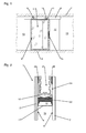
- a sliding door system is shown in front view.
- the formed in this embodiment as a sliding door leaf wing 1, which has two mutually parallel discs 2, 3, in particular glass, and at least partially arranged in the edge region 6 between the discs 2, 3 carrying and / or edge termination device is fixed to a fixed along a Building ceiling 7 arranged guide rail 8 via a guide device 9, which has two roller carriage 10 with rollers 11, slidably mounted.
- the closable by the wing 1 passage area 12 of the sliding door system is bounded laterally by building walls 13.
- One in the edge area of the wing 1 mounted handle device 15 is used for manual actuation of the wing 1.
- a power-operated displacement of the wing 1 by a drive device is conceivable.
- the wing 1 may also have a guide device, which can serve the bottom-side guide and / or locking, but not shown here.
- the wing 1 is, as can be seen in particular from the sectional view of Fig. 2 can be seen, formed as a so-called integrated all-glass wing and has two outer, designed as discs discs 2, 3, between which in the edge region 6 circumferentially a spacer 17 is arranged.
- the spacer 17 may in this case be formed in one piece and at the corners of the wing 1 each bent or -knuckled. Alternatively, the spacer 17 may be formed in several pieces, for example, per edge of the wing 1, a profile piece, wherein the profile pieces are connected to each other via corner joints.
- the spacer 17 may include in a receiving chamber 18 cooperating with the disc interior 19 air drying agent, to which the spacer 17 to the disc interior 19 has directed openings. Since the openings lie in other sectional planes, they are not shown in the drawings.
- the surface of the spacer 17 adjoining the free space 24 is circumferentially covered with a sealant 22, for example a potting compound, whereby the stability of the wing 1 and the hermetic seal are optimized.
- a sealant 22 for example a potting compound
- the edge element 16 which can be arranged in this free space 24 sections or completely encircling and is connected by an adhesive 20 with the inner sides of the discs 2, 3, is used for mounting fittings, seals or the like on the wing 1.
- the Edge element 16 is formed substantially U-shaped, wherein lateral profile legs, which are integrally connected by a profile base with each other, facing the outer edge of the wing 1.
- the two profile legs form with the profile base directed to the outer edge of the wing 1 receiving space 21 for attachment of the aforementioned fittings, seals or the like.
- the receiving space 21 is formed as an undercut groove in that the lateral profile limbs of the edge element 16 projections, in particular webs may have, and thus allows the fixation of said components, for example by with the projections verklemmbare nuts.
- the disks 2, 3 can at least in the edge region 6 covering the spacers 17 and the edge element 16 comprise a measure covering these elements, e.g. Printing, coating, surface treatment or the like.
- the edge element 16 may be formed of a glass fiber reinforced plastic (GRP).
- GRP glass fiber reinforced plastic
- the approximately equal length expansion of the disks 2, 3 and of the edge element 16 formed of fiberglass has an advantageous effect on the fatigue strength of the wing 1.
- the profiles of the edge element 16 may alternatively be formed of other suitable materials.
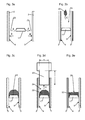
- the spacer 17 is preparatory to its the inner surfaces 4, 5 of the discs 2, 3 faces facing with sealant 23 (arrow A) and the discs 2, 3 then with the in the desired position (distance of the spacer 17 to the outer edge of the Au Shen 2, 3) pressed spacer 17 is pressed.
- the spacer 17 can also be connected in a sealing manner to the discs 2, 3 in some other way without additional sealant 22, e.g. by hot-pressing a self-sealing and adhesive spacer 23 with the disks 2, 3.
- the edges of the discs 2, 3 are masked by adhesive tape in order to protect them in the further manufacturing steps from damage and contamination.
- a sealant 22 is introduced into the free space 24 defined by the outer surface of the circumferential spacer 17 and the adjacent inner surfaces of the disks 2, 3 (arrow C).
- the sealant 22 is injected, for example by means of a nozzle in the free space 24, that the outer surface of the circumferential spacer 17 is completely covered by the sealant 24. It will be the in Fig. 3c achieved intermediate state achieved.
- the width B of the tool 25 is slightly smaller than the distance of the inner surfaces 4, 5 of the discs 2, 3, so that the tool 25 can be moved without jamming in the free space 24.
- the immersion depth T of the tool 25 is defined by supports, which rest on the outer edges of the discs 2, 3 and slide along.
- the leading edge of the tool 25 dips into the previously introduced mass of the sealant 22, so that by moving along the tool 25 along the outer edge of the wafer, the sealant 22 is leveled to a certain height defined by the tool 25. Excess sealant 22 is scraped off the tool 25 as needed.
- the sealant 22 is no longer bead-shaped, but with a relatively flat surface 26, ie it is the in Fig. 3e achieved intermediate state achieved.
- edge element 16 can be mounted on the wing 1.
- the cross-sectionally substantially U-shaped edge element 16 has below its profile base two C-shaped projections 32, which form a T-slot 27 with the profile base.
- web-shaped projections 30 are integrally formed on the outer sides of the lateral profile legs.
- the projections 32 of the profile base protrude beyond the outer surfaces of the lateral profile legs, so that correspondingly between or adjacent to the projections 30, 32 corresponding constrictions 29, 31 are present.
- web-shaped projections contact surfaces 28 are present.
- an assembly auxiliary tool 33 is connected to the edge element 16 (arrow E in FIG Fig. 3f ).
- the auxiliary assembly tool 33 is formed in cross-section substantially T-shaped and has two support legs 34 and a cylindrical shaft 35, at the lower edge there are two circular-segment-shaped contact surfaces 36.
- the width of the auxiliary assembly tool 33 is defined by the distance between two parallel flats 37 and is slightly smaller than the clear width of the receiving space 21 of the edge element 16. If the flats 37 are held at least approximately parallel to the longitudinal axis of the edge element 16, the auxiliary assembly tool 33 in introduce the receiving space 21 of the edge element 16.
- the auxiliary assembly tool 33 is rotated by 90 ° (arrow F in Fig. 3g ). Since the circular segment-shaped contact surfaces 36 have the same diametrical distance as the distance of corresponding contact surfaces 28 of the edge element 16, the contact surfaces 36 of the auxiliary assembly tool 33 come into contact with the contact surfaces 28 of the edge element 16. The support legs 34 of the auxiliary assembly tool 33 now overlap the upper edges of the lateral profile limbs of the edge element 16 and protrude beyond this ( Fig. 3h ). In this way, at least two assembly auxiliary tools 33 are placed per profile piece of the edge element 16.
- the arranged on the individual edges of the wing 1 edge elements 16 may each have a small gap at the joints of the corners, which serves for ventilation and drainage of the boundary elements 16 defined by the edge compound.
- an adhesive 20 an additional bonding between the edge element 16 and the inner surfaces 4, 5 of the discs 2, 3 introduced and thereby achieves additional bonding.
- a different section plane is shown than in Fig. 3 j because the assembly tools 33 are still mounted on the rim member 16. It is justifiable to omit the areas in which the assembly tools 33 are mounted from the adhesive 20, since these short breaks in the bond do not affect the stability of the anchoring of the marginal element 16.
- the adhesive 20, which may for example consist of the same material as the sealant 22, is preferably introduced by means of a flat nozzle into the constrictions 29 present between the inner surfaces 4, 5 of the disks 2, 3 and the lateral profile limbs of the edge element 16 (arrows H). such that after curing of the adhesive 20, removal of the auxiliary tools 33 and, if necessary, cutting off excess material of the adhesive 20 in the Fig. 2 already shown, finished state of the wing 1 is achieved. Now also the adhesive tape (not shown here) can be removed from the edges of the disks 2, 3.
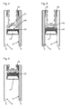
- FIG. 4 Another, opposite Fig. 2 modified embodiment of a wing 1 according to the invention is in the Fig. 4 shown.
- the profile base of the edge element 16 is arranged with its T-groove 27 spaced from the surface 26 of the sealant 22, whereby an optimal separation of the sealant 22 from the edge element 16, in particular of its adhesive 20 is achieved. This may be necessary in particular if the adhesive 20 of the edge element 16 is made of a different material than the sealant 22 and these two materials would undesirably react with each other.
- the bond is formed from an adhesive 38 deviating from the sealant 22, for example from a high-strength two-component structural adhesive.
- the edge element 16 spaced from the material of the sealant 22 may be arranged, as in the embodiment according to Fig. 4 is shown.
- FIG. 6 Another, opposite the Fig. 2 . 4 and 5 modified embodiment is in the Fig. 6 shown.
- the edge element 16 is formed with shorter side profile legs.
- the edge element 16 spaced from the material of the sealant 22 may be arranged, as in the embodiment according to Fig. 4 is shown, and / or alternatively, instead of the sealing material formed with the material 22 of the bonding therefrom a different adhesive 38 may be used, as in the embodiment according to FIG Fig. 5 is shown.
- the outer bonding may optionally even be dispensed with if the edge element 16, which is already fixed by the sealant 22 in the space 24 between the discs 2, 3, does not have to transmit high forces.
Abstract
Description
Die Erfindung betrifft einen Flügel einer Tür, eines Fensters oder dergleichen nach dem Oberbegriff des Patentanspruchs 1 sowie ein Verfahren zur Herstellung eines Flügels einer Tür, eines Fensters oder dergleichen nach dem Oberbegriff des Patentanspruchs 6.The invention relates to a wing of a door, a window or the like according to the preamble of
Aus der
Der Erfindung liegt die Aufgabe zugrunde, einen leicht montierbaren Flügel mit einer stabilen Klebeverbindung zwischen dem Randelement und den Scheiben zu schaffen.The invention has for its object to provide an easily assembled wing with a stable adhesive bond between the edge element and the discs.
Die Aufgabe wird durch die Merkmale der Patentansprüche 1 und 6 gelöst.The object is solved by the features of
Die Unteransprüche bilden vorteilhafte Ausgestaltungsmöglichkeiten der Erfindung.The subclaims form advantageous embodiments of the invention.
Erfindungsgemäß weist das Randelement an seinen den Innenflächen der Scheiben zugewandten Flächen mindestens eine Einschnürung und/oder mindestens einen Vorsprung auf, wobei der Klebstoff der Verklebung in den durch die Einschnürung und/oder den Vorsprung mit der Innenfläche der Scheibe definierten Raum einbringbar ist.According to the invention, the edge element has at least one constriction and / or at least one projection on its surfaces facing the inner surfaces of the panes, wherein the adhesive of the adhesion can be introduced into the space defined by the constriction and / or the projection with the inner surface of the pane.
Hierdurch wird eine leichte Montage des Flügels erreicht, da das Randelement ohne aufgebrachten Klebstoff in den Zwischenraum zwischen den Scheiben eingeschoben wird. Der Klebstoff wird nach Platzierung des Randelements in den hierfür definierten Raum eingebracht, wodurch sich eine saubere und stabile Verklebung des Randelements erreichen lässt.As a result, an easy assembly of the wing is achieved because the edge element is inserted without applied adhesive in the space between the discs. The adhesive is placed in the space defined for this purpose after placement of the edge element, whereby a clean and stable bonding of the edge element can be achieved.
Vor der Montage des Randelements kann ein Dichtstoff in den zur Außenkante des Flügels offenen Freiraum so eingebracht werden, dass er zumindest die zum Freiraum gerichtete Außenkante des Abstandshalters und die unmittelbar daran angrenzenden Bereiche der Innenflächen der Scheiben überdeckt und somit für eine optimale Abdichtung des Abstandshalters und somit auch des Innenraums des Flügels sorgt.Prior to assembly of the edge element, a sealant can be introduced into the open space to the outer edge of the wing so that it covers at least the free space directed to the outer edge of the spacer and the immediately adjacent areas of the inner surfaces of the discs and thus for optimum sealing of the spacer and thus also ensures the interior of the wing.
Das Randelement kann mindestens eine Ausformung, beispielsweises eine T-Nut aufweisen, welche mit dem Dichtstoff zusammenwirken kann. Durch das teilweise Eindringen des Dichtstoffs in die T-Nut wird das Randelement bereits in dem Freiraum fixiert.The edge element may have at least one molding, for example a T-groove, which can cooperate with the sealant. Due to the partial penetration of the sealant into the T-groove, the edge element is already fixed in the free space.
Das Randelement kann mindestens eine Kontaktfläche zur zumindest vorübergehenden Befestigung eines Montagehilfswerkzeugs aufweisen. Das Montagehilfswerkzeug dient zur Definition einer exakten Montageposition des Randelements in Bezug auf die Scheiben und den Abstandshalter. Hierzu kann das Montagehilfswerkzeug mindestens einen Auflageschenkel aufweisen, welcher mit zumindest einer der Scheiben in Kontakt kommt, wenn sich das Randelement in der endgültigen Montageposition befindet.The edge element may have at least one contact surface for the at least temporary attachment of a mounting auxiliary tool. The assembly tool is used to define an exact mounting position of the edge element with respect to the discs and the spacer. For this purpose, the auxiliary assembly tool can have at least one support leg, which comes into contact with at least one of the disks when the edge element is in the final assembly position.
Die Herstellung des erfindungsgemäßen Flügels kann zumindest die folgenden Verfahrensschritte umfassen:The manufacture of the wing according to the invention may comprise at least the following process steps:
Unter Verwendung eines Dichtstoffs werden die Scheiben mit dem Abstandshalter verpresst, wobei der Abstandshalter so angeordnet wird, dass zumindest abschnittsweise ein zur Außenkante des Flügels offener Freiraum gebildet wird.Using a sealant, the discs are pressed with the spacer, the spacer being arranged so as to form, at least in sections, a clearance open to the outer edge of the blade.
In den Freiraum wird weiterer Dichtstoff derart eingebracht, dass er zumindest die zum Freiraum gerichtete Außenkante des Abstandshalters und die unmittelbar daran angrenzenden Bereiche der Innenflächen der Scheiben überdeckt.In the free space further sealant is introduced such that it covers at least the outer edge of the spacer directed toward the free space and the areas of the inner surfaces of the slices immediately adjacent thereto.
Da der Dichtstoff nach seinem Einbringen eine im Wesentliche wulstförmige Kontur aufweisen kann, wird er mittels eines Werkzeugs auf eine bestimmte Höhe nivelliert. Hierbei wird gegebenenfalls überschüssiges Material des Dichtstoffs entfernt.Since the sealant can have a substantially bead-shaped contour after its introduction, it is leveled by means of a tool to a certain height. In this case, if necessary, excess material of the sealant is removed.
An dem Randelement wird vor dessen Montage am Flügel mindestens ein Montagehilfswerkzeug vorübergehend befestigt.At least one auxiliary installation tool is temporarily fixed to the wing element before it is mounted on the wing.
Das mit dem Montagehilfswerkzeug versehene Randelement wird in den Freiraum eingeführt, bis zumindest ein Auflageschenkel des Montagehilfswerkzeugs in Anlage mit zumindest einer der Scheiben kommt.The edge element provided with the auxiliary assembly tool is inserted into the free space until at least one support leg of the auxiliary assembly tool comes into contact with at least one of the disks.
Zwischen dem nun in der gewünschten Montageposition befindlichen Randelement und der Innenfläche zumindest einer der Scheiben wird ein Klebstoff eingebracht.Between the now located in the desired mounting position edge element and the inner surface of at least one of the discs, an adhesive is introduced.
Nach dem Aushärten des Klebstoffs wird das Montagehilfswerkzeug wieder entfernt, und gegebenenfalls wird überschüssiges Material des Klebstoffs entfernt.After curing of the adhesive, the assembly aid tool is removed again, and if necessary, excess material of the adhesive is removed.
Im Nachfolgenden werden Ausführungsbeispiele in der Zeichnung anhand der Figuren näher erläutert.In the following, exemplary embodiments are explained in more detail in the drawing with reference to FIGS.
Dabei zeigen:
- Fig. 1
- eine Frontansicht einer Schiebetüranlage mit einem erfindungsgemäßen Flügel;
- Fig. 2
- eine Schnittdarstellung des Randbereichs eines erfindungsgemäßen Flügels;
- Fig. 3a bis 3k
- verschiedene Schritte der Herstellung des erfindungsgemäßen Flügels gemäß
Fig. 2 ; - Fig. 4
- eine Schnittdarstellung des Randbereichs eines abgewandelten Ausführungsbeispiels eines erfindungsgemäßen Flügels;
- Fig. 5
- eine Schnittdarstellung des Randbereichs eines weiteren abgewandelten Ausführungsbeispiels eines erfindungsgemäßen Flügels;
- Fig. 6
- eine Schnittdarstellung des Randbereichs eines weiteren abgewandelten Ausführungsbeispiels eines erfindungsgemäßen Flügels.
- Fig. 1
- a front view of a sliding door system with a wing according to the invention;
- Fig. 2
- a sectional view of the edge region of a wing according to the invention;
- Fig. 3a to 3k
- various steps of the manufacture of the wing according to the invention
Fig. 2 ; - Fig. 4
- a sectional view of the edge region of a modified embodiment of a wing according to the invention;
- Fig. 5
- a sectional view of the edge region of another modified embodiment of a wing according to the invention;
- Fig. 6
- a sectional view of the edge region of another modified embodiment of a wing according to the invention.
In der
Der Flügel 1 ist, wie es insbesondere aus der Schnittdarstellung der
Der Abstandshalter 17, welches abdichtend mit den Scheiben 2, 3 verbunden, insbesondere verklebt ist und somit eine hermetische Abdichtung des Scheibeninnenraums 19 gegenüber der Umgebung gewährleistet, ist zu den Außenkanten der Flügel 1 zumindest abschnittsweise zurückgesetzt angeordnet, so dass randseitig zwischen den Scheiben 2, 3 und der Außenkante des Abstandshalters 17 ein Freiraum 24 für die Anordnung eines Randelements 16 der Trage- und/oder Randabschlusseinrichtung gebildet wird.The
Die an den Freiraum 24 angrenzende Oberfläche des Abstandshalters 17 ist umlaufend mit einem Dichtstoff 22, beispielsweise einer Vergussmasse, abgedeckt, wodurch die Stabilität des Flügels 1 sowie die hermetische Abdichtung optimiert werden.The surface of the
Das Randelement 16, welches in diesem Freiraum 24 abschnittweise oder vollständig umlaufend angeordnet werden kann und durch einen Klebstoff 20 mit den Innenseiten der Scheiben 2, 3 verbunden ist, dient zur Befestigung von Beschlägen, Dichtungen oder dergleichen am Flügel 1. In diesem Ausführungsbeispiel ist das Randelement 16 im Wesentlichen U-förmig ausgebildet, wobei seitliche Profilschenkel, welche durch eine Profilbasis einstückig miteinander verbunden sind, zur Außenkante des Flügels 1 weisen. Somit bilden die beiden Profilschenkel mit der Profilbasis einen zur Außenkante des Flügels 1 gerichteten Aufnahmeraum 21 zur Befestigung der bereits erwähnten Beschläge, Dichtungen oder dergleichen. Der Aufnahmeraum 21 ist als hinterschnittene Nut ausgebildet, indem die seitlichen Profilschenkel des Randelements 16 Vorsprünge, insbesondere Stege aufweisen können, und ermöglicht somit die Fixierung der genannten Bauteile, beispielsweise durch mit den Vorsprüngen verklemmbare Nutensteine.The
Die Scheiben 2, 3 können zumindest in dem der Abstandshalter 17 und das Randelement 16 überdeckenden Randbereich 6 eine diese Elemente abdeckende Maßnahme, z.B. Bedruckung, Beschichtung, Oberflächenbehandlung oder dergleichen, aufweisen.The
Das Randelement 16 kann aus einem glasfaserverstärkten Kunststoff (GFK) ausgebildet sein. Die annähernd gleiche Längenausdehnung der Scheiben 2, 3 und des aus GFK ausgebildeten Randelements 16 wirkt sich vorteilhaft auf die Dauerfestigkeit des Flügels 1 aus. Selbstverständlich können die Profile des Randelements 16 alternativ auch aus anderen geeigneten Materialien ausgebildet sein.The
In den
In einem ersten, in
In alternativen, hier nicht dargestellten Ausführungen kann der Abstandshalter 17 auch auf andere Weise ohne zusätzlichen Dichtstoff 22 abdichtend mit den Scheiben 2, 3 verbunden werden, z.B. durch Warmverpressen eines selbstdichtend und -klebenden Abstandshalters 23 mit den Scheiben 2, 3.In alternative embodiments, not shown here, the
Anschließend (hier nicht dargestellt) werden die Kanten der Scheiben 2, 3 durch Klebeband abgeklebt, um sie bei den weiterer Herstellungsschritten vor Beschädigung und Verschmutzung zu schützen.Subsequently (not shown here), the edges of the
Im nächsten, in
Sodann wird im nächsten, in
Nun kann das Randelement 16 am Flügel 1 montiert werden.Now the
Vor der Beschreibung der weiteren Montageschritte werden noch weitere Einzelheiten des Randelements 16 näher beschrieben: Das im Querschnitt im Wesentlichen U-förmige Randelement 16 weist unterhalb seiner Profilbasis zwei C-förmig gebogene Vorsprünge 32 auf, welche mit der Profilbasis eine T-Nut 27 bilden. An den Außenseiten der seitlichen Profilschenkel sind stegförmige Vorsprünge 30 angeformt. Auch die Vorsprünge 32 der Profilbasis ragen über die Außenflächen der seitlichen Profilschenkel hinaus, so dass entsprechend zwischen bzw. neben den Vorsprüngen 30, 32 entsprechende Einschnürungen 29, 31 vorhanden sind. Zwischen den an den Innenseiten der seitlichen Profilschenkel vorhandenen, stegförmigen Vorsprüngen sind Kontaktflächen 28 vorhanden.Prior to the description of the further assembly steps, further details of the
Im nächsten, in
In dem in
Da die Profile des Randelements 16 an den einzelnen Kanten des Flügels 1 einzeln eingesetzt werden, wird ein Wegschieben des noch weichen Dichtstoffs 22 im Eckbereich ausgeschlossen.Since the profiles of the
Die an den einzelnen Kanten des Flügels 1 angeordneten Randelemente 16 können an den Stoßstellen der Ecken jeweils einen kleinen Spalt aufweisen, welcher zur Hinterlüftung und Entwässerung des durch die Randelemente 16 definierten Randverbunds dient.The arranged on the individual edges of the
Um die Stabilität der Verbindung des Randelements 16 mit dem Flügel 1 zu optimieren, wird mit dem in
Ein weiteres, gegenüber
Ein weiteres, gegenüber den
Ein weiteres, gegenüber den
In weiteren, hier nicht dargestellten Ausführungsbeispielen kann auf die äußere Verklebung gegebenenfalls sogar verzichtet werden, wenn das Randelement 16, das bereits durch den Dichtstoff 22 in dem Freiraum 24 zwischen den Scheiben 2, 3 fixiert ist, keine hohen Kräfte übertragen muss.In further, not shown embodiments, the outer bonding may optionally even be dispensed with if the
- 11
- Flügelwing
- 22
- Scheibedisc
- 33
- Scheibedisc
- 44
- Innenflächepalm
- 55
- Innenflächepalm
- 66
- Randbereichborder area
- 77
- Gebäudedeckebuilding ceiling
- 88th
- Führungsschieneguide rail
- 99
- Führungseinrichtungguide means
- 1010
- Rollenwagenroller carriage
- 1111
- Laufrollecaster
- 1212
- DurchgangsbereichPassage area
- 1313
- Gebäudewandbuilding wall
- 1515
- Griffeinrichtunghandle means
- 1414
- Gebäudebodenbuilding floor
- 1616
- RandelementBoundary element
- 1717
- Abstandshalterspacer
- 1818
- Aufnahmekammerreceiving chamber
- 1919
- ScheibeninnenraumDisc interior
- 2020
- Klebstoffadhesive
- 2121
- Aufnahmeraumaccommodation space
- 2222
- Dichtstoffsealant
- 2323
- Dichtstoffsealant
- 2424
- Freiraumfree space
- 2525
- WerkzeugTool
- 2626
- Oberflächesurface
- 2727
- T-NutT-slot
- 2828
- Kontaktflächecontact area
- 2929
- Einschnürungconstriction
- 3030
- Vorsprunghead Start
- 3131
- Einschnürungconstriction
- 3232
- Vorsprunghead Start
- 3333
- MontagehilfswerkzeugMounting aid
- 3434
- Auflageschenkelsupporting leg
- 3535
- Schaftshaft
- 3636
- Kontaktflächecontact area
- 3737
- Abflachungflattening
- 3838
- Klebstoffadhesive
Claims (6)
mit mindestens zwei zueinander beabstandet angeordneten Scheiben (2, 3), und
mit mindestens einem Abstandshalter (17), welcher umlaufend zwischen den Scheiben (2, 3) angeordnet ist und den zwischen den Scheiben (2, 3) vorhandenen Innenraum des Flügels (1) dicht umschließt sowie zumindest abschnittsweise von den Außenkanten der Scheiben (2, 3) unter Bildung eines Freiraums (24) zurückversetzt angeordnet ist, und
mit mindestens einem zumindest abschnittsweise in dem Freiraum (24) zwischen den Scheiben (2, 3) angeordneten Randelement (16),
wobei das Randelement (16) mit mindestens einer der Scheiben (2, 3) durch eine Verklebung verbunden ist,
dadurch gekennzeichnet,
dass das Randelement (16) an seinen den Innenflächen der Scheiben (2, 3) zugewandten Flächen mindestens eine Einschnürung (29) und/oder mindestens einen Vorsprung (30) aufweist, wobei der Klebstoff (20, 38) der Verklebung in den durch die Einschnürung (29) und/oder den Vorsprung (30) mit der Innenfläche der Scheibe (2, 3) definierten Raum einbringbar ist.Wing (1) a door, a window or the like,
with at least two spaced-apart discs (2, 3), and
with at least one spacer (17), which is arranged circumferentially between the discs (2, 3) and tightly encloses the interior of the wing (1) between the discs (2, 3) and at least partially from the outer edges of the discs (2, 3). 3) is set back to form a free space (24), and
with at least one edge element (16) arranged at least in sections in the free space (24) between the panes (2, 3),
wherein the edge element (16) is connected to at least one of the panes (2, 3) by a bond,
characterized,
in that the edge element (16) has at least one constriction (29) and / or at least one projection (30) on its surfaces facing the inner surfaces of the panes (2, 3), wherein the adhesive (20, 38) of the adhesive bonds into the areas through which Constriction (29) and / or the projection (30) with the inner surface of the disc (2, 3) defined space can be introduced.
dadurch gekennzeichnet, dass ein Dichtstoff (22) in den Freiraum (24) so eingebracht ist, dass er zumindest die zum Freiraum (24) gerichtete Außenkante des Abstandshalters (17) und die unmittelbar daran angrenzenden Bereiche der Innenflächen (4, 5) der Scheiben (2, 3) überdeckt.Wing according to claim 1,
characterized in that a sealant (22) in the free space (24) is introduced so that it at least the free space (24) directed outer edge of the spacer (17) and the immediately adjacent areas of the inner surfaces (4, 5) of the discs (2, 3) covered.
dadurch gekennzeichnet, dass das Randelement (16) mindestens eine Ausformung, beispielsweise eine T-Nut (27) aufweist.A wing according to claim 1 or 2,
characterized in that the edge element (16) has at least one shape, for example a T-slot (27).
dadurch gekennzeichnet, dass das Randelement (16) mindestens eine Kontaktfläche (28) zur zumindest vorübergehenden Befestigung eines Montagehilfswerkzeugs (33) aufweist.Wing according to one or more of the preceding claims,
characterized in that the edge element (16) has at least one contact surface (28) for the at least temporary attachment of an auxiliary assembly tool (33).
dadurch gekennzeichnet, dass das Montagehilfswerkzeug (33) mindestens einen Auflageschenkel (34) aufweist, mittels dessen die Montageposition des Randelements (16) in Bezug auf mindestens eine der Scheiben (2, 3) definierbar ist.Wing according to claim 4,
characterized in that the auxiliary assembly tool (33) has at least one support leg (34), by means of which the mounting position of the edge element (16) with respect to at least one of the discs (2, 3) is definable.
wobei der Flügel (1) aufweist:
the wing (1) comprising:
Applications Claiming Priority (1)
| Application Number | Priority Date | Filing Date | Title |
|---|---|---|---|
| DE102011002676A DE102011002676A1 (en) | 2011-01-14 | 2011-01-14 | Wing of a door, a window or the like, as well as methods for producing a wing of a door, a window or the like |
Publications (1)
| Publication Number | Publication Date |
|---|---|
| EP2476851A2 true EP2476851A2 (en) | 2012-07-18 |
Family
ID=45470445
Family Applications (1)
| Application Number | Title | Priority Date | Filing Date |
|---|---|---|---|
| EP12150856A Withdrawn EP2476851A2 (en) | 2011-01-14 | 2012-01-12 | Leaf of a door, window or similar and method for producing the leaf of a door, window or similar |
Country Status (2)
| Country | Link |
|---|---|
| EP (1) | EP2476851A2 (en) |
| DE (1) | DE102011002676A1 (en) |
Cited By (2)
| Publication number | Priority date | Publication date | Assignee | Title |
|---|---|---|---|---|
| EP3192960A1 (en) * | 2016-01-12 | 2017-07-19 | AGC Glass Europe | Insulating glass unit and methods to produce it |
| EP3192959A1 (en) * | 2016-01-12 | 2017-07-19 | AGC Glass Europe | Method to produce insulating glass units and insulating glass units |
Citations (1)
| Publication number | Priority date | Publication date | Assignee | Title |
|---|---|---|---|---|
| DE19634389C2 (en) | 1996-08-26 | 2000-12-21 | Dorma Gmbh & Co Kg | Movable sliding wall |
-
2011
- 2011-01-14 DE DE102011002676A patent/DE102011002676A1/en not_active Withdrawn
-
2012
- 2012-01-12 EP EP12150856A patent/EP2476851A2/en not_active Withdrawn
Patent Citations (1)
| Publication number | Priority date | Publication date | Assignee | Title |
|---|---|---|---|---|
| DE19634389C2 (en) | 1996-08-26 | 2000-12-21 | Dorma Gmbh & Co Kg | Movable sliding wall |
Cited By (5)
| Publication number | Priority date | Publication date | Assignee | Title |
|---|---|---|---|---|
| EP3192960A1 (en) * | 2016-01-12 | 2017-07-19 | AGC Glass Europe | Insulating glass unit and methods to produce it |
| EP3192959A1 (en) * | 2016-01-12 | 2017-07-19 | AGC Glass Europe | Method to produce insulating glass units and insulating glass units |
| WO2017121600A1 (en) * | 2016-01-12 | 2017-07-20 | Agc Glass Europe | Insulating glass unit and methods to produce it |
| WO2017121601A1 (en) * | 2016-01-12 | 2017-07-20 | Agc Glass Europe | Method to produce insulating glass units |
| EA034905B1 (en) * | 2016-01-12 | 2020-04-03 | Агк Гласс Юроп | Method to produce a glass unit and glass unit |
Also Published As
| Publication number | Publication date |
|---|---|
| DE102011002676A1 (en) | 2012-07-19 |
Similar Documents
| Publication | Publication Date | Title |
|---|---|---|
| EP2476852B1 (en) | Assembly aid for a leaf of a door, window or the like | |
| DE2648295A1 (en) | GLAZING, PROCESS FOR FACTORY GLAZING OF GLASS PANES AND DEVICE FOR CARRYING OUT THE PROCESS | |
| WO2014154207A1 (en) | Structural arrangement and method for securing scaffolding to a building wall | |
| EP2508377A2 (en) | Glazing unit with sealing strip for motor vehicles windows | |
| DE202015106983U1 (en) | System for boltless fixation of a glass pane | |
| EP0825052B1 (en) | Fixing arrangement of a window pane in a motor vehicle | |
| WO2016162154A1 (en) | Method for producing blocks of windows | |
| EP2610412A1 (en) | Method and device for sealing a separation gap and anchoring seal for a separation joint | |
| DE202016101243U1 (en) | Glass clamp | |
| EP2476851A2 (en) | Leaf of a door, window or similar and method for producing the leaf of a door, window or similar | |
| DE102006054427B4 (en) | Alu-plastic window with adhesive tape fixation | |
| EP4226010A1 (en) | System, comprising a sill profiled element, a frame profiled element and a sill connector, of a window or door | |
| EP1787002B1 (en) | Set of components consisting of at least one glazing bar and at least two glazing bar end pieces for installing in an insulating glass pane | |
| EP4092240A1 (en) | New gluing technique for mounting windows | |
| DE102010009376A1 (en) | Plaster end profile for use as plaster base at e.g. ceiling wall of building, has joint sealing tape producing connection to one wall, which is connected with outer side of one leg directed towards wall | |
| DE19809537A1 (en) | Method for manufacturing automotive body panel seal anchorage point applied by direct extrusion | |
| EP3378688B1 (en) | Mounting device for use in an edge strip assembly and method for implementation in an edge strip assembly | |
| EP3064699B1 (en) | Window or door, and method for the production of same | |
| EP0110295A2 (en) | Spacer frame for edge-sealed insulating glazings | |
| DE102023128955A1 (en) | Training device for training security forces | |
| DE102005039239A1 (en) | Disk is inserted and fixed in profile frame, which has groove for its accommodation | |
| DE10111859A1 (en) | Method for joining glass components to other glass components or to profiles intended for sealing or joining of glass components involves use of an adhesive agent which is hardenable by radiation | |
| DE202015103239U1 (en) | installation equipment | |
| EP2274489B1 (en) | Device for sealing an expansion joint | |
| EP4230818A1 (en) | Auxiliary mounting device, mounting arrangement and method for mounting an enclosure on a covering device |
Legal Events
| Date | Code | Title | Description |
|---|---|---|---|
| PUAI | Public reference made under article 153(3) epc to a published international application that has entered the european phase |
Free format text: ORIGINAL CODE: 0009012 |
|
| AK | Designated contracting states |
Kind code of ref document: A2 Designated state(s): AL AT BE BG CH CY CZ DE DK EE ES FI FR GB GR HR HU IE IS IT LI LT LU LV MC MK MT NL NO PL PT RO RS SE SI SK SM TR |
|
| AX | Request for extension of the european patent |
Extension state: BA ME |
|
| STAA | Information on the status of an ep patent application or granted ep patent |
Free format text: STATUS: THE APPLICATION HAS BEEN WITHDRAWN |
|
| 18W | Application withdrawn |
Effective date: 20140110 |