EP2476842A2 - Sliding door assembly - Google Patents
Sliding door assembly Download PDFInfo
- Publication number
- EP2476842A2 EP2476842A2 EP11009497A EP11009497A EP2476842A2 EP 2476842 A2 EP2476842 A2 EP 2476842A2 EP 11009497 A EP11009497 A EP 11009497A EP 11009497 A EP11009497 A EP 11009497A EP 2476842 A2 EP2476842 A2 EP 2476842A2
- Authority
- EP
- European Patent Office
- Prior art keywords
- door
- wings
- receiving spaces
- profile
- pair
- Prior art date
- Legal status (The legal status is an assumption and is not a legal conclusion. Google has not performed a legal analysis and makes no representation as to the accuracy of the status listed.)
- Withdrawn
Links
Images


Classifications
-
- E—FIXED CONSTRUCTIONS
- E05—LOCKS; KEYS; WINDOW OR DOOR FITTINGS; SAFES
- E05D—HINGES OR SUSPENSION DEVICES FOR DOORS, WINDOWS OR WINGS
- E05D15/00—Suspension arrangements for wings
- E05D15/06—Suspension arrangements for wings for wings sliding horizontally more or less in their own plane
- E05D15/0621—Details, e.g. suspension or supporting guides
- E05D15/0626—Details, e.g. suspension or supporting guides for wings suspended at the top
- E05D15/0652—Tracks
-
- E—FIXED CONSTRUCTIONS
- E05—LOCKS; KEYS; WINDOW OR DOOR FITTINGS; SAFES
- E05D—HINGES OR SUSPENSION DEVICES FOR DOORS, WINDOWS OR WINGS
- E05D15/00—Suspension arrangements for wings
- E05D15/06—Suspension arrangements for wings for wings sliding horizontally more or less in their own plane
- E05D15/08—Suspension arrangements for wings for wings sliding horizontally more or less in their own plane consisting of two or more independent parts movable each in its own guides
-
- E—FIXED CONSTRUCTIONS
- E05—LOCKS; KEYS; WINDOW OR DOOR FITTINGS; SAFES
- E05F—DEVICES FOR MOVING WINGS INTO OPEN OR CLOSED POSITION; CHECKS FOR WINGS; WING FITTINGS NOT OTHERWISE PROVIDED FOR, CONCERNED WITH THE FUNCTIONING OF THE WING
- E05F15/00—Power-operated mechanisms for wings
- E05F15/60—Power-operated mechanisms for wings using electrical actuators
-
- E—FIXED CONSTRUCTIONS
- E05—LOCKS; KEYS; WINDOW OR DOOR FITTINGS; SAFES
- E05Y—INDEXING SCHEME RELATING TO HINGES OR OTHER SUSPENSION DEVICES FOR DOORS, WINDOWS OR WINGS AND DEVICES FOR MOVING WINGS INTO OPEN OR CLOSED POSITION, CHECKS FOR WINGS AND WING FITTINGS NOT OTHERWISE PROVIDED FOR, CONCERNED WITH THE FUNCTIONING OF THE WING
- E05Y2201/00—Constructional elements; Accessories therefore
- E05Y2201/60—Suspension or transmission members; Accessories therefore
- E05Y2201/622—Suspension or transmission members elements
- E05Y2201/684—Rails
-
- E—FIXED CONSTRUCTIONS
- E05—LOCKS; KEYS; WINDOW OR DOOR FITTINGS; SAFES
- E05Y—INDEXING SCHEME RELATING TO HINGES OR OTHER SUSPENSION DEVICES FOR DOORS, WINDOWS OR WINGS AND DEVICES FOR MOVING WINGS INTO OPEN OR CLOSED POSITION, CHECKS FOR WINGS AND WING FITTINGS NOT OTHERWISE PROVIDED FOR, CONCERNED WITH THE FUNCTIONING OF THE WING
- E05Y2400/00—Electronic control; Power supply; Power or signal transmission; User interfaces
- E05Y2400/10—Electronic control
- E05Y2400/44—Sensors therefore
-
- E—FIXED CONSTRUCTIONS
- E05—LOCKS; KEYS; WINDOW OR DOOR FITTINGS; SAFES
- E05Y—INDEXING SCHEME RELATING TO HINGES OR OTHER SUSPENSION DEVICES FOR DOORS, WINDOWS OR WINGS AND DEVICES FOR MOVING WINGS INTO OPEN OR CLOSED POSITION, CHECKS FOR WINGS AND WING FITTINGS NOT OTHERWISE PROVIDED FOR, CONCERNED WITH THE FUNCTIONING OF THE WING
- E05Y2800/00—Details, accessories and auxiliary operations not otherwise provided for
- E05Y2800/26—Form, shape
- E05Y2800/266—Form, shape curved
-
- E—FIXED CONSTRUCTIONS
- E05—LOCKS; KEYS; WINDOW OR DOOR FITTINGS; SAFES
- E05Y—INDEXING SCHEME RELATING TO HINGES OR OTHER SUSPENSION DEVICES FOR DOORS, WINDOWS OR WINGS AND DEVICES FOR MOVING WINGS INTO OPEN OR CLOSED POSITION, CHECKS FOR WINGS AND WING FITTINGS NOT OTHERWISE PROVIDED FOR, CONCERNED WITH THE FUNCTIONING OF THE WING
- E05Y2800/00—Details, accessories and auxiliary operations not otherwise provided for
- E05Y2800/26—Form, shape
- E05Y2800/27—Form, shape profiles
- E05Y2800/272—Form, shape profiles hollow
- E05Y2800/276—U-shaped
-
- E—FIXED CONSTRUCTIONS
- E05—LOCKS; KEYS; WINDOW OR DOOR FITTINGS; SAFES
- E05Y—INDEXING SCHEME RELATING TO HINGES OR OTHER SUSPENSION DEVICES FOR DOORS, WINDOWS OR WINGS AND DEVICES FOR MOVING WINGS INTO OPEN OR CLOSED POSITION, CHECKS FOR WINGS AND WING FITTINGS NOT OTHERWISE PROVIDED FOR, CONCERNED WITH THE FUNCTIONING OF THE WING
- E05Y2900/00—Application of doors, windows, wings or fittings thereof
- E05Y2900/10—Application of doors, windows, wings or fittings thereof for buildings or parts thereof
- E05Y2900/13—Application of doors, windows, wings or fittings thereof for buildings or parts thereof characterised by the type of wing
- E05Y2900/132—Doors
Definitions
- the invention relates to a sliding door system and in particular an automatic, so powered sliding door system, the sliding door leaves are thus moved by a motor.
- Such door systems are known per se. They are mounted by the door leaf suspension is attached to a door reveal, which is formed for example by means of an opening of a building wall or a fixed frame profile.
- door panels for example, are usually opened and closed manually in restaurants between the guest room and the kitchen area.
- double swing door systems use, which are provided in each case only for one or both passage direction (s).
- a thereby required manual door operation by the service personnel can bring hygienic problems.
- Another problem of such door systems is the risk of collision due to the door area, which can still be frequented in both directions. This is particularly large when a person approaches a door opening in their direction and the door wings are opaque, so that it is difficult or impossible to recognize the door opening and respond in a timely manner.
- the object of the invention is to at least reduce the disadvantages of the prior art.
- a sliding door system has at least two door leaves.
- the system also includes a guide profile with at least two receiving spaces.
- a respective one of a pair of associated ones of the at least two door leaves is received with a portion guided along a respective travel path.
- the receiving spaces thus define the course of the travel path of each recorded door leaf.
- the resulting two traverse paths extend such that the door wings of this pair of wings received are arranged independently of each other from any open position at any time movable. Ie. At no time does a door protrude into the travel path of the other, associated door leaf.
- the only one guide profile sums up the aforementioned pair of received door panels as belonging to the sliding door system.
- the result is a modular and simply constructed sliding door system. This multiple guide profile allows space-saving sliding doors that can be used in the aforementioned areas.
- the principle of the sliding door makes it possible to avoid the aforementioned collision or injury hazards.
- each door is provided with a rotor of an associated linear motor.
- a stator of the respectively associated linear motor which can be brought into interaction with the latter along its respective travel path, is arranged stationarily in relation to the other door system.
- the system is at any time able to move the door leaves of each pair completely independent of each other; Many operating scenarios can be realized. Since the receiving spaces accommodate both parts of the linear motors and each door is assigned a "separate" linear motor, eliminating other force-transmitting elements such as rotating drive belt and the like.
- the multiple guide drive profile thus facilitates the assembly, since no more cumbersome several profiles must be mounted aligned.
- both receiving spaces of the guide profile extend parallel to one another.
- This solution offers the possibility of being able to provide very narrow guide profiles and thus visually advantageous door systems. In particular, in glass door systems, this is usually important.
- these receiving spaces extend along a respective straight line or a circular arc. It can be realized with the invention so easily classic sliding door systems;
- the guide profile can be designed as a classic, box-like and elongated part.
- At least one stop element is at least in one of the two receiving spaces of the guide profile stationarily inserted so that it projects into the travel path of the door also recorded. Ie. this stopper limits the travel of the associated, arranged in the same receiving space door leaf. This is a special one easy way to customize the travel on site, for example, shorten, to be able. In addition, retrofitting and replacement in the event of a defect or the like are possible. Also, this can be taken from the relevant door.
- At least one of the at least two receiving spaces extends beyond the travel path defined by it, ie it is longer than the actual travel path of the door leaf received therein.
- a part of the receiving space is not used by the received door leaf and can serve, for example, the attachment of additional components such as sensors, other fastening parts, a stop member, a controller or the like.
- this at least one receiving space extends over an entire length of the guide profile. This allows a particularly simple production. If all receiving spaces are formed continuously, it is possible to produce the guide profile from an extruded profile, which is particularly inexpensive and simple.
- the receiving space can either define that the associated door can be moved along the entire guide profile. Or, as stated above, it may serve to attach additional components.
- the system preferably also has at least one fixed wing. This is therefore arranged stationary with respect to the other system. He is also arranged so that each door of the recorded at least one pair of wings, seen in the direction of Be, in the closed position in front of or behind the fixed wing. Ie. when opening the respective door this is in Begehungscardi gradually from Fixed wing covered. This allows a spatial separation of the door openings releasable from the door wings from each other and thus the possibility of assigning the two door openings optically different passage directions.
- the fixed wing is attached to the guide profile. Ie. the building in which the sliding door system is used, must be set up only for fastening the guide profile and any floor guide of the movable pair of wings.
- this allows a simple adaptation of the fixed wing position on site. This is particularly easy if the fixed wing is clamped on corresponding clamping parts only on the guide profile; Holes or the like are not required. This also promotes easy installation.
- the sliding door system preferably also has a respective sensor system for each door leaf of the at least one recorded wing pair in or on the guide profile. This can be set up, at least in part, when activated to actuate the linear motor of the respective door leaf, to move the associated door leaf in a predetermined direction and / or to stop or lock.
- the sensor system may comprise several types of sensor elements, such as motion detectors, main closure edge protection, smoke detectors, and the like.
- the sensor system of one door leaf of the at least one pair of housed wings can be arranged at least partially in the extended or continuous receiving space of the other door leaf of the at least one pair of wings received outside the travel path of the other door leaf.
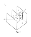
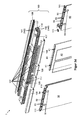
- FIG. 1 shows a sliding door system 1 according to a first embodiment of the invention.
- the system 1 here comprises two trained as a sliding door sash 50, which are exemplarily not visible here, above arranged fittings 51 suspended in a likewise not visible here, later explained in more detail drive profile 130 and taken guided along the marked by a block arrow directions. Both wings 50 are closed. Between the driving wings 50 an immovable fixed wing 40 is arranged. Ie. the driving wings 50 are moved when opening example behind the fixed wing 40.
- a transverse element 5 is arranged, which connects two side walls 3 of the sliding door system 1 with each other. It can be designed, for example, as a skylight.
- the drive profile 130 is attached to two externally arranged posts 10 set up on a floor 2, of which only the right one is visible. Furthermore, extending from the drive profile 130 and cross member 5 outgoing a separation or intermediate wall 4 in the direction of Be the sliding door system 1, which is formed by way of example by means of a framed fixed wing.
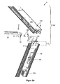
- FIG. 2a shows the sliding door system 1 in the region of attachment between an upper horizontal frame profile 30 of the intermediate wall 4 an outer post 10 and the now visible drive profile 130 of a drive part 100.
- the drive part 100 includes in the invention all parts that are necessary, one of the wings 50th to proceed.
- the frame profile 30 is screwed via a mounting bracket 32 by means of screws 33 with the outer post 10, namely its threaded openings 11, and thus securely fastened.
- the mounting bracket 30 is braced by means of screws 31 in the frame section 30.
- the outer post 10 here has a fastening section 12 on the upper side, likewise with threaded openings 11.
- screws 101 are screwed in, which were previously passed through a mounting bracket 102 of the drive member 100.
- the mounting bracket 102 like the mounting bracket 32 now clamped in the drive part 130 or, as here, by means of screws 103 are firmly screwed.
- the latter variant is used for secure fixation of the profiles 130, 10 to each other.
- non-visible outer post 10 creates a self-supporting frame that can be positioned and mounted as a whole, which simplifies the entire assembly.
- the outer post 10 there is a power supply unit 104 and a circuit 105, for example in the form of a sensor and / or control circuit for the other, recorded in the drive profile 130 linear drive.
- the drive profile 130 only has to accommodate the stator (s) (not illustrated here) from here by way of example two linear motors and optionally provide a guidance of the driving wings 50.
- the stator (s) may be distributed over the entire length of the drive profile 130 in accordance with desired drive forces, without regard to additional parts such as sensors or the like.
- FIG. 2b shows the sliding door system 1 in the field of attachment between intermediate sections 20, frame profiles 30 and drive profile 130.
- the frame profiles 30 are screwed by means of differently shaped fastening parts 32 and screws 33 in threaded openings 24 of a respective intermediate profile 20.
- the right frame profile 30 is attached to the outer post 10, whereas the left frame profile 30 is secured via a cross-sectionally approximately T-shaped fastening part 32 and screws 33 here at the middle intermediate post 20.
- This attachment part 32 has the basic shape of However, it additionally has a now third leg, which extends from the inserted into the frame section 30 legs substantially perpendicularly and away from the legs bolted to the intermediate post 20. About screws 35, this leg is screwed to a plate-like part 34. This part 34 in turn is inserted in a recess 106 formed as a mounting groove of the drive profile 130 and fixed, for example by means of screws.
- FIG. 3a shows the front of the sliding door system 1 of FIG. 1 without walls 3, 4 and cross member 5.
- the door leaves 40, 50 are not sufficient for example to the floor 2 but are spaced therefrom.
- the drive part 100 comprises by way of example two drive profiles 130 arranged in a row, which, viewed in the direction of the bevel, are closed off at the front and rear sides by means of at least one respective side panel 108.
- the side panel 108 on the front side is not shown, so that cable guides 107 arranged by way of example can be seen by way of example.
- FIG. 3b shows the same arrangement from a different perspective.
- the aforementioned fittings 51 can be seen, with the aid of which the door leaves 50 are accommodated in the drive profile 130.
- Figure 3c shows a detail of the arrangement of FIG. 3b , only without door 50.
- the right and left suspension bracket 51 of the left and right door 50 are shown.
- At the upper end is followed by a later explained in more detail carriage 52, which is recorded guided in the drive profile 130.
- the fixed wing 40 which is otherwise not shown, is advantageously fastened to the drive profile 130 via a receiving profile 43.
- the receiving profile 43 opens on the upper side in two tab-like mounting bracket 41, which are screwed by screws 42 on the drive profile 130.
- the other fixed wing 40 is supported here from below in a corresponding receiving groove 44 of the receiving profile 43.
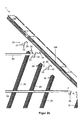
- FIG. 3d figure shows the arrangement of FIG. 3a in a partial exploded view.
- the here two suspension fittings 51 each door 50 open into each one of the aforementioned carriage 52.
- rollers 53 At its in or opposite to the direction of loading facing sides partially provided with reference numerals rollers 53 are arranged, the associated carriage 52 in a facing this, so here lower subspace 142 of a later explained in more detail receiving space 140 of the respective drive profile 130 along the travel path of the respective attached door leaf 50 lead.
- the carriages 52 are provided with a rotor part 54 on their side facing the drive profile 130, or they each form one.
- the rotor parts 54 each have a number of permanent magnets.
- the drive profile 130 is divided into two parts. Ie. the drive part 100 comprises two drive profiles 130, which abut each other on the front side and are arranged stationary relative to one another. The arrangement is such that the receiving spaces 140 of both profiles 130 are aligned with each other and thus form an entire receiving space 140.
- the rear subspace 142 of the right-hand drive profile 130 is at least partially covered in the direction of the door leaves 40, 50 by means of a cover panel 110.
- the left door 50 is received in here rear compartment 142 of the left drive profile 130.
- the front subspace 142 of the left drive profile 130 is also at least partially covered on the side facing the left door leaf 50 by means of a now second cover panel 110.
- the cover panels 110 are therefore arranged outside the travel paths of the door leaves 50.
- stoppers 111 are shown.
- the door leaves 50 are in the closed position and therefore abut or lie in the direction of the closed position on the left or right stopper 111.
- the other two stoppers 111 are arranged in relation to the respective nearest door leaf 50 in relation to this other subspace 142 of the drive profiles 130. Ie. they limit the movement of each received in the same subspace 142 door 50 in the opening direction and thus define its maximum opening width.
- the stoppers 111 are fastened in the respective subspace 142, for example by means of bracing.
- the stoppers 111 can be locked from the underside.
- the end positions of the door leaves 50 can be adjusted on site.
- the subspaces 142 or receiving spaces 140 of the drive profile 130 are separated from one another due to an intermediate wall 137 arranged therebetween and therefore run parallel to one another.
- the fastening profile 41 fastened or formed on the receiving profile 43 can be seen.
- the aforementioned cable guides 107 are attached to the outside of the respective drive profile 130 and serve the protected laying of energy and / or data lines, for example, to the aforementioned stators and possibly to other components such as sensors or the like.
- the drive profile 130 is provided with passage openings 117, which serve to pass lines from the direction of the cable guides 107 into a respective compartment 141, which forms the second part of the respective receiving space 140.
- a smoke detector may be used in the respective subspace 142 in the region of the respective cover panel 110.
- the cover panel 110 is interrupted in the detection range of the smoke detector or provided with holes.
- the drive profile arrangement formed in this way is optically closed at the front and at the rear, visually by means of the aforementioned side panels 108, viewed laterally or in the direction of loading.
- magnet rows formed here by means of respective permanent magnets are mounted as rotor parts 54 on the respective carriage 52. Further, the positions of the stoppers 111 with respect to the carriages 52 can be seen. From left, the first and third stoppers 111 are associated with the left carriage 52. All these elements are therefore arranged in the same, here rear receiving space 142 of the receiving profiles 130. Accordingly, the group right stator and, from left, second and fourth stopper 111 in the front receiving space 142 of the receiving profiles 130 is arranged.
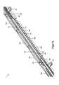
- FIG. 3e shows the arrangement of 3d figure diagonally from below.
- the stators are particularly easy to recognize.
- they essentially each consist of two stator modules 112 and a Hall sensor 118 arranged between them.
- Each stator module 112 is formed by way of example by means of a series of electric coils, which are connected in the usual way and optionally each provided with a magnetic magnetic return body.
- the stators are arranged one behind the other as seen in the direction of loading.
- the left stator is arranged in the rear receiving space 141 of the drive profile 130, whereas the right stator is arranged in the front receiving space 141 of the drive profile 130.
- the respective rotor (or carriage 52) is located below the associated stator. Ie. Each carriage 52 or attached to it, pointing in the direction of the stator permanent magnets are in energization of the associated stator with this in electromagnetic interaction, which can cause a movement of the carriage 52 and thus of the attached wing 50.
- the rollers 53 guide the associated carriage 52 in the respective receiving space 142 at least in the direction of the stator, to ensure the necessary minimum distance between stator and rotor.
- the stoppers 111 are also disposed in a respective one of the receiving spaces 142 and define the end positions of the associated carriage 52 and thus limit the travel of the associated wing 50.
- Activation sensors for example in the form of motion sensors, are shown here in an exemplary manner in front of and behind the left or right stator. These are therefore accommodated in the region of the respective receiving space 141 in which the stator is not arranged with taken.
- a controller 119 is arranged as the second component, which serves the operation of at least one of the stators and thus the linear motors.
- the drive profile 130 is preferably covered in the direction of carriage 52 by means of a cover panel 110 and thus protected against contamination, access, sabotage and the like.
- the cover panel 110 is transparent to the sensor or pierced in the sensor detection area. Ie. the sensor can "work through the cover panel 110".
- FIG. 3f It is in cross-section substantially U-shaped and open in the direction of wings 40, 50 and thus includes a non-descript cavity.
- right and left are on a crosspiece 136, the side legs 135 enclosing the U and these together connects, upper latching recesses 132 formed, engage in the corresponding latching projections 113 of a respective side panel 108.
- Lower detent recesses 132 are formed here like an undercut at the free end of each side leg 135.
- each successive projections 138 divide the respective receiving space 140 in the aforementioned upper and lower receiving space 141 and 142, respectively;
- Each receiving space 140 is divided into two.
- the here two receiving spaces 141 are used to hold stationary parts of the wing system 1, which may not be located in particular in the travel path of each suspended wing 50. This relates mainly to the respective tread 50 belonging stator 112 but also any additional elements such as the aforementioned sensors.
- projections 138 with their sides facing the transverse web 136, preferably serve as a support for the elements or components accommodated in the respectively associated receiving space 141.
- the carriages 52 of the here two driving wings 50 each have rollers 53 on both sides, which are displaced vertically relative to each other are arranged.
- the left rear and right front rollers 53 of the carriages 52 belong to one group, while the left front and right rear rollers 53 of the carriages 52 belong to the other group.
- the axes of rotation of the rollers 53 of the one group are shifted in relation to the rollers 53 of the other group in the direction of the transverse web 136.
- rollers 53 roll on in the direction of carriage 52 facing surfaces of the side legs 135 and the intermediate wall 137 centrally formed projections 138, while the rollers 53 of the other group on in the direction of these projections 138 facing surfaces of the free ends of the side legs 135th and the intermediate wall 137 unrolled projections 138 roll.
- the carriages 52 are thus held in a tilt-proof manner in the respective receiving space 142.
- the respective rotor part 54 is arranged on the transverse web 136 facing side of the carriage 52.
- the cable guides 107 indicated above have, viewed in cross-section, a respective receiving space 115 which is open at one location. Not shown cables or lines can be pressed through this point in ebenjenen receiving space 115 or else pushed along the front side into the receiving space 115 and thus securely laid.
- the drive profile 130 on its side legs 135 by way of example in cross-section C-shaped grooves 131, engage in the corresponding projections 120 of the respective cable guide 107 and thus securely fix the cable guide 107 on the drive profile 130.
- the receiving groove 131 preferably serves another purpose.
- the aforementioned plate-like parts 34 are designed to be inserted in the receiving groove 131 stationary.
- Below the grooves 131 are located on the outer sides of the side legs 135 by way of example additional grooves 139, in which, for example, the aforementioned plate-like parts 25 are used stationary.
- the components arranged here between the drive profile 130 and the wings 40, 50 are additionally accommodated in the drive profile 130.
- the cover panels 110 are arranged below the drive profile 130 and are preferably supported or attached to the surfaces of the lower projections 138 pointing in the direction of wings 40, 50.
- a stator module 112 is shown above the stoppers 111 and a component in the form of a controller 119 of the linear motor arranged on the right is shown on the left, which is accommodated in a stationary manner in the respective receiving space 141.
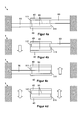
- FIG. 4 shows a sliding door system 1 according to a second embodiment of the invention from above and in various operating conditions. It is in turn designed as a double-leaf sliding door and inserted between two walls 3 and opposite sides of a door frame or the like. Ie. Stopper 111 can be dispensed with at these points as wing end positions. In Begehungscardi, here in the vertical direction, are located approximately in the center both in front of and behind the treads 50 two fixed wings 40. These preferably have the still outstanding stopper 111 on. These are integrally formed on the respective fixed wing 40 or attached. Because of the optics, the stoppers 111 preferably extend along the entire, associated fixed wing and thus additionally close it optically outward.
- a drive profile 130 which is designed as for the linear motors and the wing suspension as in the first embodiment of the invention.
- the block arrows indicate the respective direction of movement of the sliding door system 1.
- FIG. 4a shows the sliding door system 1 in the closed state.
- the dashed lines indicated end position of the tiller 50 represents their respective fully open position.
- an activation element not shown in detail, for example in the form of an opening switch, motion detector or the like.
- the activation element is advantageously arranged in the receiving space 140 of the drive profile 130. If the drive profile 130 with its two receiving spaces 140 extends over the entire width of the system, the activation element can be arranged, for example, of the right-hand wing 50 in the entire receiving space 140, in which the left-hand wing 50 is partially accommodated, in the area to the right Fixed wing 40, so outside the travel of the left wing 50th
- FIG. 4b shows a state after the left activating element is operated and then the associated, left driving wing 50 has been opened. In this state, the left door area can be passed down here. Thereafter, the left tiller 50 is closed again.
- Figure 4c shows the analog state for the right-hand drive wing 50. Thereafter, the right wing 50 is preferably also closed again, so that the in FIG. 4a shown position is reached again.
- FIG. 5 shows a sliding door system 1 according to a third embodiment of the invention also in different operating positions. It is designed as a double arch sliding door in the form of a lock.
- This sliding door system 1 is bordered by two walls 3 or the like in Begehungscardi exemplary.
- the driving wings 50 which are located diagonally opposite one another here, are moved synchronously with one another.
- an intermediate wall 4 which divides the passage created by the walls 3 in two part-passages.
- the intermediate wall 4 opens at its end facing a respective pair of vanes 50 in a portion corresponding to the function of one of the fixed wings 40 FIG. 4 takes over.
- the intermediate wall 4 has at said ends in each case via a stopper 111 which limits the movement of the respective closest of the two inner tails 50 in the opening direction and thus defines its fully open position.
- a Festerie140 is arranged, each of the function of the other of the fixed wing 40 according to FIG. 4 takes and also for the nearest tiller 50 has a stopper 111.
- FIG. 5a shows the sliding door system 1 in the closed state.
- FIG. 5b shows a state after one of these two activation elements has been actuated and then the left upper and the lower right traveling wings 50 have been opened. In this state, the passages released by these two vanes 50 can thus be passed here, left to the bottom or right to the top. Thereafter, both wings 50 are closed again.
- FIG. 5c the condition of Appendix 1 after completion of this process.
- the sliding door system 1 can be left.
- the upper right and left lower wings 50 are closed again, so that the in FIG. 5a shown position is reached again.
- this sliding door system 1 may be provided to completely release the passage, so all wings 50 to open completely. This condition is in FIG. 5d shown. In this latter case, in turn, an ascent in both directions is possible, again characterized by double block arrows.
- FIG. 6 shows a sliding door system 1 according to a fourth embodiment of the invention. It is essentially like the sliding door system 1 according to FIG. 5 designed. However, fixed wings 40 and stoppers 111 are missing here. In addition, the intermediate wall 4 lacks the end sections described above, which assume the function of a fixed wing 40 in each case.
- the intermediate wall 4 divides here also created by the walls 3 passage in two part-passages.
- the movement of the wings 80 is limited by the walls 3 and the stopper attached thereto, thus defining its fully open position. Therefore, separate stoppers 111 are not required.
- Figure 6a and Figure 6b show the sliding door system 1 each in the closed state, except that the respective top and bottom pairs of turrets 50 have exchanged their positions to each other.
- both pairs of wings 50 are formed and arranged so that they are in each end position, in the direction of Be, according to FIG. 6 So seen in the vertical direction, always close one of the partial passages and release the other.
- FIG. 6c shows a state after one of the activating elements of each upper left or lower right fl oor 50 has been operated, and then left upper and lower right fl oors 50 have been opened. Ie. depending on the closed position of the wings 50 according to FIG. 6a or FIG. 6b The outer and inner tails 50 are each moved so that the partial passages top left and bottom right is released. Therefore, in this state, the partial passages released by the vanes 50 can be passed again left to the bottom or right to the top.
- both tails 50 are closed again so that they also release the other part of each passage.
- FIG. 6d shows the condition of Appendix 1 after completion of this process.
- the sliding door system 1 can be left.
- each one of the upper and lower wings 50 is again moved so that one of the in Figure 6a and Figure 6b shown positions reached again.
- the drive profile 130 may also have more receiving spaces 140 instead of two. Instead of the side panels 108, the drive profile 130 itself may form the optical termination to the outside.
- the receiving spaces 140 of the drive profile 130 can each also accommodate a plurality of stators and so serve as the formation of a four-leaf sliding door system.
- the wings 50 can of course be moved according to other operating scenarios due to the respective own linear motor drive.
- the wings 50 according to FIG. 4 can be moved synchronously with each other or in dependence on each other.
- the wings 50 according to FIG. 5 and FIG. 6 can be moved individually independently of each other or in groups.
- each receiving space 140 stators of several driving wings 50 can be arranged.
- double telescopic sliding door systems can be realized.
- Each telescoping sliding door panel comprises, for example, two partial wings, which are accommodated in different receiving spaces 142 of the associated drive profile / s 130.
- the pairs of inner and outer part wings in the direction of access are in each case arranged in the same receiving space 142 of the drive profile / s 130. Under certain circumstances, two continuous receiving spaces 140 may also be sufficient in this case.
- the aforementioned embodiments can also be realized without a motor drive.
- the rotor parts 54 and stators are eliminated.
- the drive profiles 130 can be modified such that they only have the receiving spaces 142 as receiving spaces 140. This allows flatter and thus optically advantageous thus pure guide profiles. Furthermore, the advantage remains to be able to use in the guide profile, for example, sensors in areas that is not used by any of the wings 50 in.
- the invention provides a simply constructed, mounted and universally operable sliding door system.
- this sliding door system it is possible to control the flow of passers-by, which at least reduces the risk of collision.
Abstract
Description
Die Erfindung betrifft eine Schiebetüranlage und insbesondere eine automatische, also motorisch betriebene Schiebetüranlage, deren Schiebetürflügel also motorisch bewegt werden.The invention relates to a sliding door system and in particular an automatic, so powered sliding door system, the sliding door leaves are thus moved by a motor.
Solche Türanlagen an sich sind bekannt. Sie werden montiert, indem die Türflügelaufhängung an einer Türlaibung befestigt wird, die beispielsweise mittels einer Öffnung einer Gebäudewand oder eines Festrahmenprofils gebildet ist.Such door systems are known per se. They are mounted by the door leaf suspension is attached to a door reveal, which is formed for example by means of an opening of a building wall or a fixed frame profile.
Allerdings werden Türflügel beispielsweise in Gaststätten zwischen Gastraum und Küchenbereich üblicherweise manuell geöffnet und geschlossen. Es finden beispielsweise Doppelpendeltüranlagen Verwendung, die jeweils nur für eine oder beide Durchgangsrichtung(en) vorgesehen sind. Eine dadurch erforderliche manuelle Türbetätigung durch das Servicepersonal kann hygienische Probleme mit sich bringen. Ein anderes Problem derartiger Türanlagen ist die aufgrund des weiterhin in beide Richtungen frequentierbaren Türbereichs entstehende Kollisionsgefahr. Diese ist besonders groß, wenn sich eine Person einem sich in ihre Richtung öffnenden Türflügel nähert und die Türflügel undurchsichtig sind, sodass es nicht oder nur schwer möglich ist, die Türöffnung zu erkennen und rechtzeitig zu reagieren.However, door panels, for example, are usually opened and closed manually in restaurants between the guest room and the kitchen area. There are, for example, double swing door systems use, which are provided in each case only for one or both passage direction (s). A thereby required manual door operation by the service personnel can bring hygienic problems. Another problem of such door systems is the risk of collision due to the door area, which can still be frequented in both directions. This is particularly large when a person approaches a door opening in their direction and the door wings are opaque, so that it is difficult or impossible to recognize the door opening and respond in a timely manner.
Würden solche Türflügel nun noch automatisiert, also mit einem motorischen Antrieb versehen, erhöhte sich die Kollisions- und/oder Verletzungsgefahr womöglich.Would such doors now still automated, so provided with a motor drive, the risk of collision and / or increased risk possibly.
Aufgabe der Erfindung ist es, die Nachteile des Standes der Technik zumindest zu verringern.The object of the invention is to at least reduce the disadvantages of the prior art.
Diese Aufgabe wird durch den Gegenstand des Anspruchs 1 gelöst. Vorteilhafte Weiterbildungen der Erfindung sind in den Unteransprüchen angegeben.This object is solved by the subject matter of
Eine erfindungsgemäße Schiebetüranlage weist zumindest zwei Türflügel auf. Die Anlage umfasst zudem ein Führungsprofil mit zumindest zwei Aufnahmeräumen. In jedem Aufnahmeraum ist ein jeweiliger eines Paars einander zugehöriger der zumindest zwei Türflügel mit einem Abschnitt entlang eines jeweiligen Verfahrwegs geführt aufgenommen. Die Aufnahmeräume definieren somit den Verlauf des Verfahrwegs des jeweils aufgenommenen Türflügels. Die sich daraus ergebenden zwei Verfahrwege erstrecken sich derart, dass die Türflügel dieses aufgenommenen Flügelpaars jederzeit aus jeder Öffnungsstellung heraus unabhängig voneinander bewegbar angeordnet sind. D. h. zu keinem Zeitpunkt ragt ein Türflügel in den Verfahrweg des jeweils anderen, zugehörigen Türflügels. Damit können die Türflügel des jeweiligen Paars zu jedem Zeitpunkt völlig unabhängig voneinander bewegt werden. Das lediglich eine Führungsprofil fasst dabei das vorgenannte Paar von aufgenommenen Türflügeln als zur Schiebetüranlage zugehörig zusammen. Es entsteht eine modulartige und einfach aufgebaute Schiebetüranlage. Dieses Mehrfachführungsprofil erlaubt platzsparende Schiebetüren, die in den vorgenannten Bereichen eingesetzt werden können. Das Prinzip der Schiebetür ermöglicht dabei die Vermeidung der vorgenannten Kollisions- bzw. Verletzungsgefahren.A sliding door system according to the invention has at least two door leaves. The system also includes a guide profile with at least two receiving spaces. In each receiving space, a respective one of a pair of associated ones of the at least two door leaves is received with a portion guided along a respective travel path. The receiving spaces thus define the course of the travel path of each recorded door leaf. The resulting two traverse paths extend such that the door wings of this pair of wings received are arranged independently of each other from any open position at any time movable. Ie. At no time does a door protrude into the travel path of the other, associated door leaf. Thus, the door leaves of each pair can be moved completely independently of each other at any time. The only one guide profile sums up the aforementioned pair of received door panels as belonging to the sliding door system. The result is a modular and simply constructed sliding door system. This multiple guide profile allows space-saving sliding doors that can be used in the aforementioned areas. The principle of the sliding door makes it possible to avoid the aforementioned collision or injury hazards.
Vorzugsweise ist jeder Türflügel mit einem Läufer eines zugehörigen Linearmotors versehen. Für jeden Läufer des jeweils aufgenommenen Türflügels ist entsprechend im jeweils zugehörigen Aufnahmeraum des Führungsprofils zudem ein mit diesem entlang dessen jeweiligen Verfahrwegs antreibend in Wechselwirkung bringbarer Stator des jeweils zugehörigen Linearmotors in Bezug auf die sonstige Türanlage ortsfest angeordnet. Damit ist die Anlage zu jedem Zeitpunkt in der Lage, die Türflügel des jeweiligen Paars völlig unabhängig voneinander zu bewegen; es lassen sich vielerlei Betriebsszenarien realisieren. Da die Aufnahmeräume sowohl Teile der Linearmotoren aufnehmen und jedem Türflügel ein "eigener" Linearmotor zugeordnet ist, entfallen anderweitige kraftübertragende Elemente wie umlaufender Antriebsriemen und dergleichen. Das somit Mehrfachführungs-Antriebsprofil erleichtert die Montage, da nicht mehr umständlich mehrere Profile zueinander ausgerichtet montiert werden müssen.Preferably, each door is provided with a rotor of an associated linear motor. For each runner of each recorded door leaf is correspondingly in the respective associated receiving space of the guide profile Moreover, a stator of the respectively associated linear motor, which can be brought into interaction with the latter along its respective travel path, is arranged stationarily in relation to the other door system. Thus, the system is at any time able to move the door leaves of each pair completely independent of each other; Many operating scenarios can be realized. Since the receiving spaces accommodate both parts of the linear motors and each door is assigned a "separate" linear motor, eliminating other force-transmitting elements such as rotating drive belt and the like. The multiple guide drive profile thus facilitates the assembly, since no more cumbersome several profiles must be mounted aligned.
Vorzugsweise verlaufen beide Aufnahmeräume des Führungsprofils parallel zueinander. Diese Lösung bietet die Möglichkeit, sehr schmale Führungsprofile und damit optisch vorteilhafte Türanlagen bereitstellen zu können. Insbesondere bei Glastüranlagen ist dies in der Regel von Bedeutung.Preferably, both receiving spaces of the guide profile extend parallel to one another. This solution offers the possibility of being able to provide very narrow guide profiles and thus visually advantageous door systems. In particular, in glass door systems, this is usually important.
Zusätzlich oder alternativ verlaufen diese Aufnahmeräume entlang einer jeweiligen Geraden oder eines Kreisbogens. Es lassen sich mit der Erfindung also ohne weiteres klassische Schiebetüranlagen realisieren; das Führungsprofil kann als klassisches, boxartiges und längliches Teil ausgebildet werden.Additionally or alternatively, these receiving spaces extend along a respective straight line or a circular arc. It can be realized with the invention so easily classic sliding door systems; The guide profile can be designed as a classic, box-like and elongated part.
Vorzugsweise ist zumindest in einem der zwei Aufnahmeräume des Führungsprofils zumindest ein Anschlagelement ortsfest so eingesetzt, dass es in den Verfahrweg des ebenfalls aufgenommenen Türflügel ragt. D. h. dieses Anschlagelement begrenzt den Verfahrweg des zugehörigen, im selben Aufnahmeraum angeordneten Türflügels. Dies ist eine besonders einfache Möglichkeit, den Verfahrweg vor Ort anpassen, beispielsweise verkürzen, zu können. Zudem sind eine Nachrüstung und ein Austausch bei einem Defekt oder dergleichen möglich. Auch kann dadurch der betreffende Türflügel entnommen werden.Preferably, at least one stop element is at least in one of the two receiving spaces of the guide profile stationarily inserted so that it projects into the travel path of the door also recorded. Ie. this stopper limits the travel of the associated, arranged in the same receiving space door leaf. This is a special one easy way to customize the travel on site, for example, shorten, to be able. In addition, retrofitting and replacement in the event of a defect or the like are possible. Also, this can be taken from the relevant door.
Vorzugsweise erstreckt sich zumindest einer der zumindest zwei Aufnahmeräume über den von ihm definierten Verfahrweg hinaus, ist also länger als der eigentliche Verfahrweg des darin aufgenommenen Türflügels. Dadurch wird ein Teil des Aufnahmeraums nicht vom aufgenommenen Türflügel genutzt und kann beispielsweise dem Anbringen zusätzlicher Komponenten wie einer Sensorik, anderer Befestigungsteile, eines Anschlagteils, einer Steuerung oder dergleichen dienen.Preferably, at least one of the at least two receiving spaces extends beyond the travel path defined by it, ie it is longer than the actual travel path of the door leaf received therein. As a result, a part of the receiving space is not used by the received door leaf and can serve, for example, the attachment of additional components such as sensors, other fastening parts, a stop member, a controller or the like.
Zusätzlich oder alternativ erstreckt sich dieser zumindest eine Aufnahmeraum über eine gesamte Länge des Führungsprofils. Dies erlaubt eine besonders einfache Herstellung. Sind alle Aufnahmeräume durchgehend ausgebildet, bietet sich die Möglichkeit, das Führungsprofil aus einem Strangprofil herzustellen, was besonders preisgünstig und einfach ist. Der Aufnahmeraum kann dabei entweder definieren, dass der zugehörige Türflügel entlang des gesamten Führungsprofils bewegt werden kann. Oder aber er kann, wie vorstehend angegeben, dem Anbringen zusätzlicher Komponenten dienen.Additionally or alternatively, this at least one receiving space extends over an entire length of the guide profile. This allows a particularly simple production. If all receiving spaces are formed continuously, it is possible to produce the guide profile from an extruded profile, which is particularly inexpensive and simple. The receiving space can either define that the associated door can be moved along the entire guide profile. Or, as stated above, it may serve to attach additional components.
Zusätzlich oder alternativ zu den vorstehend angegebenen Lösungen weist die Anlage vorzugsweise ferner zumindest einen Festflügel auf. Dieser ist also in Bezug auf die sonstige Anlage ortsfest angeordnet. Er ist zudem so angeordnet, dass sich jeder Türflügel des aufgenommenen zumindest einen Flügelpaars, in Begehungsrichtung gesehen, in Schließstellung vor oder hinter dem Festflügel befindet. D. h. beim Öffnen des jeweiligen Türflügels wird dieser in Begehungsrichtung nach und nach vom Festflügel überdeckt. Dies ermöglicht eine räumliche Trennung der von den Türflügeln freigebbaren Türöffnungen voneinander und damit die Möglichkeit, die somit zwei Türöffnungen optisch verschiedenen Durchgangsrichtungen zuzuordnen.In addition or as an alternative to the solutions indicated above, the system preferably also has at least one fixed wing. This is therefore arranged stationary with respect to the other system. He is also arranged so that each door of the recorded at least one pair of wings, seen in the direction of Be, in the closed position in front of or behind the fixed wing. Ie. when opening the respective door this is in Begehungsrichtung gradually from Fixed wing covered. This allows a spatial separation of the door openings releasable from the door wings from each other and thus the possibility of assigning the two door openings optically different passage directions.
Vorteilhafterweise ist der Festflügel am Führungsprofil befestigt. D. h. das Gebäude, in dem die Schiebetüranlage eingesetzt ist, muss lediglich zur Befestigung des Führungsprofils und einer etwaigen Bodenführung des bewegbaren Flügelpaars eingerichtet sein. Zudem erlaubt dies eine einfache Anpassung der Festflügelposition vor Ort. Dies ist besonders einfach, wenn der Festflügel über entsprechende Klemmteile nur am Führungsprofil festgeklemmt ist; Bohrungen oder dergleichen sind nicht erforderlich. Dies fördert zudem eine einfache Montage.Advantageously, the fixed wing is attached to the guide profile. Ie. the building in which the sliding door system is used, must be set up only for fastening the guide profile and any floor guide of the movable pair of wings. In addition, this allows a simple adaptation of the fixed wing position on site. This is particularly easy if the fixed wing is clamped on corresponding clamping parts only on the guide profile; Holes or the like are not required. This also promotes easy installation.
Die erfindungsgemäße Schiebetüranlage weist vorzugsweise ferner für jeden Türflügel des zumindest einen aufgenommenen Flügelpaars im oder am Führungsprofil eine jeweilige Sensorik auf. Diese kann zumindest in Teilen eingerichtet sein, bei Aktivierung den Linearmotor des jeweiligen Türflügels zu betätigen, den zugehörigen Türflügel in eine vorbestimmte Richtung zu bewegen und/oder anzuhalten bzw. zu verriegeln. D. h. die Sensorik kann mehrere Arten von Sensorelementen wie Bewegungsmelder, Hauptschließkantenabsicherung, Rauchmelder und dergleichen umfassen.The sliding door system according to the invention preferably also has a respective sensor system for each door leaf of the at least one recorded wing pair in or on the guide profile. This can be set up, at least in part, when activated to actuate the linear motor of the respective door leaf, to move the associated door leaf in a predetermined direction and / or to stop or lock. Ie. The sensor system may comprise several types of sensor elements, such as motion detectors, main closure edge protection, smoke detectors, and the like.
Wie vorstehend bereits angegeben, kann die Sensorik eines Türflügels des zumindest einen aufgenommenen Flügelpaars zumindest teilweise im verlängerten bzw. durchgehenden Aufnahmeraum des anderen Türflügels des zumindest einen aufgenommenen Flügelpaars außerhalb des Verfahrwegs des anderen Türflügel angeordnet sein.As already stated above, the sensor system of one door leaf of the at least one pair of housed wings can be arranged at least partially in the extended or continuous receiving space of the other door leaf of the at least one pair of wings received outside the travel path of the other door leaf.
Weitere Merkmale und Vorteile der Erfindung ergeben sich aus der nachfolgenden Beschreibung bevorzugter Ausführungsformen. Es zeigen:
Figur 1- eine Schiebetüranlage gemäß einer ersten Ausführungsform der Erfindung,
Figur 2- die Befestigung zwischen dem Antriebsprofil und Pfosten der
Schiebetüranlage von Figur 1 , Figur 3- die
Schiebetüranlage von Figur 1 hinsichtlich des Aufbaus des motorischen Antriebs, Figur 4- eine Schiebetüranlage gemäß einer zweiten Ausführungsform der Erfindung,
Figur 5- eine Schiebetüranlage gemäß einer dritten Ausführungsform der Erfindung und
Figur 6- eine Schiebetüranlage gemäß einer vierten Ausführungsform der Erfindung.
- FIG. 1
- a sliding door system according to a first embodiment of the invention,
- FIG. 2
- the attachment between the drive profile and posts of the sliding door system of
FIG. 1 . - FIG. 3
- the sliding door system of
FIG. 1 in terms of the structure of the motor drive, - FIG. 4
- a sliding door system according to a second embodiment of the invention,
- FIG. 5
- a sliding door system according to a third embodiment of the invention and
- FIG. 6
- a sliding door system according to a fourth embodiment of the invention.
Oberhalb der Türflügel 40, 50 ist ein Querelement 5 angeordnet, das zwei Seitenwände 3 der Schiebetüranlage 1 miteinander verbindet. Es kann beispielsweise als Oberlicht ausgebildet sein.Above the door leaves 40, 50, a
Das Antriebsprofil 130 ist an zwei außen angeordneten, auf einem Boden 2 aufgestellten Pfosten 10 befestigt, von denen nur der rechte sichtbar ist. Ferner erstreckt sich vom Antriebsprofil 130 bzw. Querelement 5 abgehend eine Trenn- oder Zwischenwand 4 in Begehungsrichtung der Schiebetüranlage 1, die beispielhaft mittels eines gerahmten Festflügels gebildet ist.The
Alternativ fehlt bzw. fehlen Querelement 5, Außenpfosten 10 und/oder Seitenwände 3. In dem Fall ist das Antriebsprofil 130 oberseitig z. B. an einer Raumdecke befestigt.Alternatively missing or missing
Das Rahmenprofil 30 ist über einen Befestigungswinkel 32 mithilfe von Schrauben 33 mit dem Außenpfosten 10, nämlich dessen Gewindeöffnungen 11, verschraubt und damit sicher befestigt. Dabei ist der Befestigungswinkel 30 mittels Schrauben 31 im Rahmenprofil 30 verspannt. Der Außenpfosten 10 weist hier oberseitig einen Befestigungsabschnitt 12 ebenfalls mit Gewindeöffnungen 11. In die sind Schrauben 101 eingeschraubt, die vorher durch einen Befestigungswinkel 102 des Antriebsteils 100 hindurchgeführt wurden. Der Befestigungswinkel 102 kann wie der Befestigungswinkel 32 nunmehr im Antriebsteil 130 verspannt oder, wie hier, mithilfe von Schrauben 103 fest verschraubt werden. Die letztgenannte Variante dient der sicheren Fixierung der Profile 130, 10 aneinander. In Verbindung mit dem anderen, nicht sichtbaren Außenpfosten 10 entsteht ein selbsttragender Rahmen, der so im Gesamten aufgestellt und montiert werden kann, was die gesamte Montage vereinfacht.The
Wie ferner zu erkennen, befinden sich im Außenpfosten 10 hier ein Netzteil 104 und eine Schaltung 105 beispielsweise in Form einer Sensor- und/oder Ansteuerungsschaltung für den sonstigen, im Antriebsprofil 130 aufgenommenen Linearantrieb. Das Antriebsprofil 130 muss lediglich den bzw. die hier nicht dargestellten Stator/en von hier beispielhaft zwei Linearmotoren aufnehmen und gegebenenfalls eine Führung der Fahrflügel 50 bieten. Der bzw. die Stator/en kann bzw. können über die gesamte Länge des Antriebsprofils 130 gemäß den gewünschten Antriebskräften verteilt werden, ohne Rücksicht auf zusätzliche Teile wie Sensoren oder dergleichen nehmen zu müssen.As can further be seen, in the
Das rechte Rahmenprofil 30 ist am Außenpfosten 10 angebracht, wohingegen das linke Rahmenprofil 30 über ein im Querschnitt in etwa T-förmiges Befestigungsteil 32 und Schrauben 33 hier am mittleren Zwischenpfosten 20 befestigt ist. Dieses Befestigungsteil 32 hat die Grundform des vorbeschriebenen Befestigungsteils 32. Allerdings weist es zusätzlich einen nunmehr dritten Schenkel auf, der sich vom in das Rahmenprofil 30 eingeschobenen Schenkel im Wesentlichen senkrecht und von dem am Zwischenpfosten 20 angeschraubten Schenkel weg erstreckt. Über Schrauben 35 ist dieser Schenkel mit einem plattenartigen Teil 34 verschraubt. Dieses Teil 34 wiederum ist in einer als Befestigungsnut ausgebildeten Aufnahme 106 des Antriebsprofils 130 eingeschoben und beispielsweise mittels Schraubens fixiert.The
Am rechten und linken Zwischenpfosten 20 sind eigene Befestigungsteile 22 angebracht, indem Schrauben 23 durch die Befestigungsteile 22 hindurchgehend analog den Befestigungsteilen 32 in zugehörige Gewindeöffnungen 24 des jeweiligen Zwischenpfostens 20 eingeschraubt sind. Auch die Befestigungsteile 22 sind über hier jeweils eine Schraube 21 mit einem plattenartigen Teil 25 verschraubt, das die gleiche Funktion wie das plattenförmige Teil 34 hat.On the right and left
Beispielhaft ist das Antriebsprofil 130 zweigeteilt. D. h. das Antriebsteil 100 umfasst zwei Antriebsprofile 130, die stirnseitig aneinander anstoßen und zueinander ortsfest angeordnet sind. Die Anordnung ist derart, dass die Aufnahmeräume 140 beider Profile 130 miteinander fluchten und somit einen gesamten Aufnahmeraum 140 bilden.By way of example, the
Der hier hintere Teilraum 142 des rechten Antriebsprofils 130 ist in Richtung Türflügel 40, 50 zumindest teilweise mittels einer Abdeckblende 110 abgedeckt. Dies bedeutet, dass der Laufwagen 52 des rechten Türflügels 50 im hier vorderen Teilraum 142 des rechten Antriebsprofils 130 aufgenommen ist. Dementsprechend ist der linke Türflügel 50 im hier hinteren Teilraum 142 des linken Antriebsprofils 130 aufgenommen. Auch wenn nicht erkennbar, ist auch der vordere Teilraum 142 des linken Antriebsprofils 130 an der dem linken Türflügel 50 zugewandten Seite ebenfalls mittels einer nunmehr zweiten Abdeckblende 110 zumindest teilweise abgedeckt. Die Abdeckblenden 110 sind also außerhalb der Verfahrwege der Türflügel 50 angeordnet.The
Ferner sind vier Stopper 111 dargestellt. Die Türflügel 50 befinden sich in Schließstellung und stoßen bzw. liegen daher in Richtung Schließstellung am ganz links bzw. rechts angeordneten Stopper 111 an. Dies bedeutet, dass die entstehenden Paare von Stoppern 111 und in Geschlossenstellung anliegendem Türflügel 50 jeweils im selben Teilraum 142 angeordnet sind. Die anderen zwei Stopper 111 sind in Bezug auf den jeweils nächstliegenden Türflügel 50 im zu diesem anderen Teilraum 142 der Antriebsprofile 130 angeordnet. D. h. sie begrenzen die Bewegung des jeweils im selben Teilraum 142 aufgenommenen Türflügels 50 in Öffnungsrichtung und definieren damit dessen maximale Öffnungsweite. Die Stopper 111 sind im jeweiligen Teilraum 142 beispielsweise mittels Verspannens befestigt. Vorzugsweise sind die Stopper 111 von der Unterseite her arretierbar. So können die Endpositionen der Türflügel 50 vor Ort eingestellt werden.Further, four
Die Teilräume 142 bzw. Aufnahmeräume 140 des Antriebsprofils 130 sind aufgrund einer dazwischen angeordneten Zwischenwand 137 voneinander separiert und verlaufen daher parallel zueinander.The
Hinsichtlich des Festflügels 40 sind die am Aufnahmeprofil 43 befestigten oder angeformten Befestigungswinkel 41 zu erkennen.With regard to the fixed
Die vorgenannten Kabelführungen 107 sind außenseitig am jeweiligen Antriebsprofil 130 befestigt und dienen dem geschützten Verlegen von Energie- und/oder Datenleitungen beispielsweise zu den vorgenannten Statoren und ggf. zu anderen Komponenten wie Sensoren oder dergleichen. An vorbestimmten Stellen ist das Antriebsprofil 130 mit Durchgangsöffnungen 117 versehen, die dem Durchführen von Leitungen aus Richtung der Kabelführungen 107 in einen jeweiligen Teilraum 141 dienen, der den zweiten Teil des jeweiligen Aufnahmeraums 140 bildet.The aforementioned cable guides 107 are attached to the outside of the
Beispielsweise kann im jeweiligen Teilraum 142 im Bereich der jeweiligen Abdeckblende 110 ein Rauchmelder eingesetzt sein. Zur Luftzirkulation ist die Abdeckblende 110 im Erfassungsbereich des Rauchmelders unterbrochen oder mit Löchern versehen.For example, a smoke detector may be used in the
Die so gebildete Antriebsprofilanordnung ist seitlich bzw. in Begehungsrichtung gesehen vorn und hinten optisch mittels der vorgenannten Seitenblenden 108 abgeschlossen.The drive profile arrangement formed in this way is optically closed at the front and at the rear, visually by means of the
Schließlich sind hier mittels jeweiliger Permanentmagneten gebildete Magnetreihen als Läuferteile 54 am jeweiligen Laufwagen 52 angebracht. Ferner sind die Positionen der Stopper 111 in Bezug auf die Laufwagen 52 zu erkennen. Von links der erste und dritte Stopper 111 sind dem linken Laufwagen 52 zugeordnet. All diese Elemente sind daher im selben, hier hinteren Aufnahmeraum 142 der Aufnahmeprofile 130 angeordnet. Dementsprechend ist die Gruppe rechter Stator und, von links, zweiter und vierter Stopper 111 im hier vorderen Aufnahmeraum 142 der Aufnahmeprofile 130 angeordnet.Finally, magnet rows formed here by means of respective permanent magnets are mounted as
Die Statoren sind in Begehungsrichtung gesehen hintereinander angeordnet. Der linke Stator ist im hinteren Aufnahmeraum 141 des Antriebsprofils 130 angeordnet, wohingegen der rechte Stator im vorderen Aufnahmeraum 141 des Antriebsprofils 130 angeordnet ist.The stators are arranged one behind the other as seen in the direction of loading. The left stator is arranged in the
Zur Bildung eines jeweiligen linearmotorbasierten Antriebs befindet sich der jeweilige Läufer (bzw. Laufwagen 52) unterhalb des zugehörigen Stators. D. h. jeder Laufwagen 52 bzw. die an ihm angebrachten, in Richtung Stator weisenden Permanentmagnete stehen bei Bestromung des zugehörigen Stators mit diesem in elektromagnetischer Wechselwirkung, die eine Bewegung des Laufwagens 52 und damit des angehängten Flügels 50 bewirken kann. Die Laufrollen 53 führen den zugehörigen Laufwagen 52 im jeweiligen Aufnahmeraum 142 zumindest in Richtung Stator, um den notwendigen Mindestabstand zwischen Stator und Läufer zu gewährleisten.To form a respective linear motor-based drive, the respective rotor (or carriage 52) is located below the associated stator. Ie. Each
Die Stopper 111 sind ebenfalls in einem jeweiligen der Aufnahmeräume 142 angeordnet und definieren die Endpositionen des zugehörigen Laufwagens 52 und begrenzen so den Verfahrweg des zugehörigen Flügels 50.The
Hier vor bzw. hinter dem linken bzw. rechten Stator befinden sich exemplarisch Aktivierungssensoren beispielsweise in Form von Bewegungssensoren. Diese sind daher in dem Bereich des jeweiligen Aufnahmeraums 141 aufgenommen, in dem der mit aufgenommene Stator nicht angeordnet ist. Zusätzlich ist als zweite Komponente eine Steuerung 119 angeordnet, die dem Betrieb zumindest eines der Statoren und damit der Linearmotoren dient.Activation sensors, for example in the form of motion sensors, are shown here in an exemplary manner in front of and behind the left or right stator. These are therefore accommodated in the region of the
Zumindest in Bereichen, in denen weder Stator noch Sensor bzw. Steuerung 119 angeordnet sind, ist das Antriebsprofil 130 in Richtung Laufwagen 52 vorzugsweise mittels einer Abdeckblende 110 abgedeckt und damit vor Verschmutzung, Zugriff, Sabotage und dergleichen geschützt.At least in areas in which neither stator nor sensor or
Alternativ ist die Abdeckblende 110 hinsichtlich des Sensors transparent oder im Sensor-Erfassungsbereich durchbrochen. D. h. der Sensor kann "durch die Abdeckblende 110 hindurch" arbeiten.Alternatively, the
Die vorgenannte, mittig angeordnete und im Wesentlichen parallel zu den Seitenschenkeln 135 verlaufende Zwischenwand 137 teilt den vorgenannten Hohlraum in zwei vorzugsweise identisch gestaltete Aufnahmeräume 140. Es entstehen also im Querschnitt exemplarisch zwei nebeneinander liegende Aufnahmeräume 140. An den Seitenschenkeln 135 und der Zwischenwand 137 etwa mittig ausgebildete, sich jeweils aufeinander zu erstreckende Vorsprünge 138 teilen den jeweiligen Aufnahmeraum 140 in den vorgenannten oberen und unteren Aufnahmeraum 141 bzw. 142 auf; jeder Aufnahmeraum 140 ist zweigeteilt. Die hier zwei Aufnahmeräume 141 dienen der Aufnahme ortsfester Teile der Flügelanlage 1, die sich insbesondere nicht im Verfahrweg des jeweils aufgehängten Fahrflügels 50 befinden dürfen. Dies betrifft hauptsächlich den zum jeweiligen Fahrflügel 50 gehörenden Stator 112 aber auch etwaige zusätzliche Elemente wie die vorgenannten Sensoren.The above, centrally arranged and substantially parallel to the
Diese Vorsprünge 138 dienen mit ihren dem Quersteg 136 zugewandten Seiten vorzugsweise als Auflage für die im jeweils zugehörigen Aufnahmeraum 141 aufgenommenen Elemente bzw. Komponenten.These
An den freien Enden der Seitenschenkel 135 und der Zwischenwand 137 sind sich jeweils aufeinander zu erstreckende Vorsprünge 138 ausgebildet. Wie zu erkennen, weisen die Laufwagen 52 der hier zwei Fahrflügel 50 jeweils beidseitig Laufrollen 53 auf, die zueinander vertikal verschoben angeordnet sind. Es gibt somit zwei Gruppen von Laufrollen 53 mit jeweils in einer vertikalen Höhe gleich angeordneten Rotationsachsen. Hier exemplarisch die linken hinteren und rechten vorderen Laufrollen 53 der Laufwagen 52 gehören zu der einen Gruppe, während die linken vorderen und rechten hinteren Laufrollen 53 der Laufwagen 52 zur anderen Gruppe gehören. Die Rotationsachsen der Laufrollen 53 der einen Gruppe sind gegenüber den Laufrollen 53 der anderen Gruppe in Richtung Quersteg 136 verschoben. Daher rollen diese Laufrollen 53 auf in Richtung Laufwagen 52 weisenden Flächen der an den Seitenschenkeln 135 und der Zwischenwand 137 mittig ausgebildeten Vorsprüngen 138 ab, während die Laufrollen 53 der anderen Gruppe auf in Richtung ebendieser Vorsprünge 138 weisenden Flächen der an den freien Enden der Seitenschenkel 135 und der Zwischenwand 137 ausgebildeten Vorsprünge 138 abrollen. Damit sind die Laufwagen 52 kippsicher im jeweiligen Aufnahmenraum 142 geführt aufgenommen. Auf der in Richtung Quersteg 136 weisenden Seite der Laufwagen 52 ist das jeweilige Läuferteil 54 angeordnet.At the free ends of the
Die vorstehend angegebenen Kabelführungen 107 weisen, im Querschnitt gesehen, einen jeweiligen, an einer Stelle offenen Aufnahmeraum 115 auf. Nicht dargestellte Kabel bzw. Leitungen können durch diese Stelle hindurch in ebenjenen Aufnahmeraum 115 eingedrückt oder aber auch längs stirnseitig in den Aufnahmeraum 115 eingeschoben und damit sicher verlegt werden. Zur Befestigung weist das Antriebsprofil 130 an seinen Seitenschenkeln 135 exemplarisch im Querschnitt C-förmige Aufnahmenuten 131 auf, in die korrespondierende Vorsprünge 120 der jeweiligen Kabelführung 107 eingreifen und damit die Kabelführung 107 sicher am Antriebsprofil 130 fixieren.The cable guides 107 indicated above have, viewed in cross-section, a
Die Aufnahmenut 131 dient vorzugsweise noch einem anderen Zweck. Vorteilhafterweise sind die vorgenannten plattenartigen Teile 34 gestaltet, in die Aufnahmenut 131 ortsfest eingesetzt zu werden. Unterhalb der Aufnahmenuten 131 befinden sich an den Außenseiten der Seitenschenkel 135 exemplarisch zusätzliche Aufnahmenuten 139, in die beispielsweise die vorgenannten plattenartigen Teile 25 ortsfest eingesetzt sind.The receiving
Die hier zwischen dem Antriebsprofil 130 und den Flügeln 40, 50 angeordneten Komponenten sind zusätzlich im Antriebsprofil 130 aufgenommen. Die Abdeckblenden 110 sind unterhalb des Antriebsprofils 130 angeordnet und vorzugsweise an den in Richtung Flügel 40, 50 weisenden Flächen der unteren Vorsprünge 138 abgestützt bzw. angebracht.The components arranged here between the
Über den Abdeckblenden 110 sind Stopper 111 abgebildet, die im jeweiligen Aufnahmeraum 142 ortsfest aufgenommen sind.Over the
Über den Stoppern 111 wiederum sind links ein Statormodul 112 und rechts eine Komponente in Form einer Steuerung 119 des hier rechts angeordneten Linearmotors abgebildet, die im jeweiligen Aufnahmeraum 141 ortsfest aufgenommen sind.In turn, a
Auch wenn hier nicht dargestellt, befindet sich oberhalb der Flügel 40, 50 wiederum ein Antriebsprofil 130, das hinsichtlich der Linearmotoren und der Flügelaufhängung wie bei der ersten Ausführungsform der Erfindung gestaltet ist.Although not shown here, above the
Die Blockpfeile geben die jeweilige Begehungsrichtung der Schiebetüranlage 1 an.The block arrows indicate the respective direction of movement of the sliding
Wird das Aktivierungselement betätigt, indem beispielsweise ein Objekt wie eine Person in dessen Erfassungsbereich gelangt, bewirkt dies ein Öffnen des in Begehungsrichtung dahinter angeordneten Fahrflügels 50.
Werden beide Aktivierungselemente im Wesentlichen gleichzeitig betätigt, ist ein Zustand gemäß
Zwischen den Wänden 3 verläuft eine Zwischenwand 4, die den durch die Wände 3 geschaffenen Durchgang in zwei Teil-Durchgänge aufteilt. Die Zwischenwand 4 mündet an ihren einem jeweiligen Paar von Flügeln 50 zugewandten Ende in einen Abschnitt, der die Funktion eines der Festflügel 40 gemäß
Zugleich, zeitlich gesteuert oder aber aufgrund des Feststellens des Geschlossenzustands der soeben geschlossenen Flügel 50 bzw. der Betätigung eines nunmehr oberhalb des linken unteren bzw. unterhalb des rechten oberen Fahrflügels 50 angeordneten Aktivierungselements wird nun das andere Paar Flügel 50 geöffnet.
Alternativ kann auch diese Schiebetüranlage 1 vorgesehen sein, den Durchgang komplett freizugeben, also alle Flügel 50 vollständig zu öffnen. Dieser Zustand ist in
Die Zwischenwand 4 teilt auch hier den durch die Wände 3 geschaffenen Durchgang in zwei Teil-Durchgänge. Die Bewegung der Flügel 80 wird durch die Wände 3 bzw. daran angebrachte Stopper begrenzt und damit dessen Vollständig-Offen-Stellung definiert. Daher sind gesonderte Stopper 111 nicht erforderlich.The
Danach werden vorzugsweise beide Fahrflügel 50 wieder geschlossen, sodass sie zugleich den jeweils anderen Teildurchgang freigeben.Thereafter, preferably both
Zugleich, zeitlich gesteuert oder aber aufgrund des Feststellens des Geschlossenzustands der soeben geschlossenen Flügel 50 bzw. der Betätigung eines nunmehr oberhalb des linken unteren bzw. unterhalb des rechten oberen Fahrflügels 50 angeordneten Aktivierungselements werden nun noch die anderen zwei Flügel 50 derart bewegt, dass auch sie den vorgenannten, jeweils anderen Teildurchgang freigeben.
Die Erfindung ist nicht auf die vorbeschriebenen Ausführungsformen beschränkt.The invention is not limited to the above-described embodiments.
Anstelle eines Laufwagens 52 pro Fahrflügel 50 kann es mehrere Laufwagen 52 geben. Die Anzahl an Beschlägen 51 kann variieren. Das Antriebsprofil 130 kann anstelle zweier auch mehr Aufnahmeräume 140 aufweisen. Anstelle der Seitenblenden 108 kann das Antriebsprofil 130 selbst den optischen Abschluss nach außen bilden. Die Aufnahmeräume 140 des Antriebsprofils 130 können jeweils auch mehrere Statoren aufnehmen und so beispielsweise der Bildung einer vierflügeligen Schiebetüranlage dienen.Instead of a
Bei den vorgenannten Ausführungsformen können die Flügel 50 aufgrund des jeweils eigenen Linearmotorantriebs selbstredend auch gemäß anderen Betriebsszenarien bewegt werden. Die Flügel 50 gemäß
In jedem Aufnahmeraum 140 können Statoren mehrerer Fahrflügel 50 angeordnet sein. Es sind beispielsweise Doppel-Teleskopschiebetüranlagen realisierbar. Jeder Teleskopschiebetürflügel umfasst beispielsweise zwei Teilflügel, die in verschiedenen Aufnahmeräumen 142 des/r zugehörigen Antriebsprofils/e 130 aufgenommen sind. Die in Begehungsrichtung Paare innerer und äußerer Teilflügel sind jeweils im selben Aufnahmeraum 142 des/r Antriebsprofils/e 130 angeordnet. Es reichen also unter Umständen auch in diesem Fall zwei durchgehende Aufnahmeräume 140 aus.In each receiving
Die vorgenannten Ausführungsformen sind auch ohne motorischen Antrieb realisierbar. In dem Fall entfallen die Läuferteile 54 und Statoren. Die Antriebsprofile 130 sind derart modifizierbar, dass sie nur noch die Aufnahmeräume 142 als Aufnahmeräume 140 aufweisen. Dies erlaubt flachere und damit optisch vorteilhafte somit reine Führungsprofile. Weiterhin bleibt der Vorteil bestehen, in das Führungsprofil beispielsweise Sensoren in Bereichen einsetzen zu können, die von keinem der Flügel 50 in genutzt wird.The aforementioned embodiments can also be realized without a motor drive. In that case, the
Im Ergebnis ist durch die Erfindung eine einfach aufgebaute, zu montierende und universell betreibbare Schiebetüranlage geschaffen. Zudem ist es mit dieser Schiebetüranlage möglich, den Strom von Passanten zu steuern, wodurch die Kollisionsgefahr zumindest verringert ist.As a result, the invention provides a simply constructed, mounted and universally operable sliding door system. In addition is With this sliding door system, it is possible to control the flow of passers-by, which at least reduces the risk of collision.
- 11
- Schiebetüranlagesliding door system
- 22
- Bodenground
- 33
- Wandwall
- 44
- Zwischenwandpartition
- 55
- Querelementcrossmember
- 66
- Pfostenpost
- 1010
- Außenpfostenthe post
- 1111
- Gewindeöffnungthreaded opening
- 1212
- Befestigungsabschnittattachment section
- 2020
- Zwischenprofilintermediate profile
- 2121
- Schraubescrew
- 2222
- Befestigungsteilattachment portion
- 2323
- Schraubescrew
- 2424
- Gewindeöffnungthreaded opening
- 2525
- plattenartiges Teilplate-like part
- 3030
- Rahmenprofilframe profile
- 3131
- Schraubescrew
- 3232
- Befestigungsteilattachment portion
- 3333
- Schraubescrew
- 3434
- plattenartiges Teilplate-like part
- 3535
- Schraubescrew
- 4040
- Festflügelfixed wing
- 4141
- Befestigungswinkelmounting brackets
- 4242
- Schraubescrew
- 4343
- AufnahmeprofilUp profile
- 4444
- Aufnahmenutreceiving groove
- 5050
- FahrflügelMoving leaf
- 5151
- Hängebeschlagwall bracket
- 5252
- Laufwagencarriage
- 5353
- Laufrollecaster
- 5454
- Läuferteilrotor part
- 100100
- Antriebsteildriving part
- 101101
- Schraubescrew
- 102102
- Befestigungswinkelmounting brackets
- 103103
- Schraubescrew
- 104104
- Netzteilpower adapter
- 105105
- Schaltungcircuit
- 106106
- Aufnahmeadmission
- 107107
- Kabelführungcable management
- 108108
- Seitenblendeside panel
- 109109
- Kabelelectric wire
- 110110
- Abdeckblendecover panel
- 111111
- Stopperstopper
- 112112
- Statormodulstator module
- 113113
- Rastvorsprungcatch projection
- 114114
- Rastvorsprungcatch projection
- 115115
- Aufnahmeraumaccommodation space
- 116116
- Anschlagattack
- 117117
- Durchführungexecution
- 118118
- Hall-SensorHall sensor
- 119119
- Steuerungcontrol
- 120120
- Rastvorsprungcatch projection
- 130130
- Antriebsprofildrive profile
- 131131
- Aufnahmenutreceiving groove
- 132132
- Rastausnehmungrecess
- 133133
- Aufnahmenutreceiving groove
- 134134
- LaufflächenvorsprungTread edge
- 135135
- Seitenschenkelside leg
- 136136
- Querstegcrosspiece
- 137137
- Zwischenwandpartition
- 138138
- Vorsprunghead Start
- 139139
- Aufnahmenutreceiving groove
- 140140
- Aufnahmeraumaccommodation space
- 141141
- Teilraumsubspace
- 142142
- Teilraumsubspace
Claims (11)
Applications Claiming Priority (1)
| Application Number | Priority Date | Filing Date | Title |
|---|---|---|---|
| DE201110000132 DE102011000132A1 (en) | 2011-01-14 | 2011-01-14 | sliding system |
Publications (2)
| Publication Number | Publication Date |
|---|---|
| EP2476842A2 true EP2476842A2 (en) | 2012-07-18 |
| EP2476842A3 EP2476842A3 (en) | 2015-03-18 |
Family
ID=45218178
Family Applications (1)
| Application Number | Title | Priority Date | Filing Date |
|---|---|---|---|
| EP11009497.6A Withdrawn EP2476842A3 (en) | 2011-01-14 | 2011-12-01 | Sliding door assembly |
Country Status (2)
| Country | Link |
|---|---|
| EP (1) | EP2476842A3 (en) |
| DE (1) | DE102011000132A1 (en) |
Cited By (3)
| Publication number | Priority date | Publication date | Assignee | Title |
|---|---|---|---|---|
| EP3411551A4 (en) * | 2016-02-01 | 2019-11-06 | Technologies Lanka Inc. | Door actuators, integrated door actuator and method of operating a door actuator of a transit vehicle |
| KR20200062279A (en) * | 2017-10-26 | 2020-06-03 | 중산 오파이크 하드웨어 프로덕츠 컴퍼니 리미티드 | Linear motor for sliding door |
| KR20200128380A (en) * | 2018-02-02 | 2020-11-12 | 중산 오파이크 하드웨어 프로덕츠 컴퍼니 리미티드 | Linear motor structure for telescopic sliding doors |
Families Citing this family (1)
| Publication number | Priority date | Publication date | Assignee | Title |
|---|---|---|---|---|
| AT521133B1 (en) * | 2018-11-14 | 2019-11-15 | Blum Gmbh Julius | Guide system for guiding a movably mounted door leaf |
Family Cites Families (5)
| Publication number | Priority date | Publication date | Assignee | Title |
|---|---|---|---|---|
| EP1403459A2 (en) * | 2002-09-27 | 2004-03-31 | Walter Meusburger | Partition wall with horizontally sliding elements |
| DE102007032476A1 (en) * | 2007-07-10 | 2009-01-29 | Dorma Gmbh + Co. Kg | Carrier device for a sliding door |
| DE102007038840A1 (en) * | 2007-08-16 | 2009-02-19 | Dorma Gmbh + Co. Kg | Linear drive for sliding doors or the like |
| DE102007038847A1 (en) * | 2007-08-16 | 2009-02-19 | Dorma Gmbh + Co. Kg | Stator for a linear motor |
| WO2009026634A1 (en) * | 2007-08-29 | 2009-03-05 | Aneeta Window Systems (Vic) Pty Ltd | Sliding windows, doors and the like |
-
2011
- 2011-01-14 DE DE201110000132 patent/DE102011000132A1/en not_active Withdrawn
- 2011-12-01 EP EP11009497.6A patent/EP2476842A3/en not_active Withdrawn
Non-Patent Citations (1)
| Title |
|---|
| None |
Cited By (8)
| Publication number | Priority date | Publication date | Assignee | Title |
|---|---|---|---|---|
| EP3411551A4 (en) * | 2016-02-01 | 2019-11-06 | Technologies Lanka Inc. | Door actuators, integrated door actuator and method of operating a door actuator of a transit vehicle |
| US11001277B2 (en) | 2016-02-01 | 2021-05-11 | Technologies Lanka Inc. | Door actuators, integrated door actuator and method of operating a door actuator of a transit vehicle |
| KR20200062279A (en) * | 2017-10-26 | 2020-06-03 | 중산 오파이크 하드웨어 프로덕츠 컴퍼니 리미티드 | Linear motor for sliding door |
| EP3703230A4 (en) * | 2017-10-26 | 2020-12-09 | Zhongshan Opike Hardware Product Co., Ltd | Linear motor for sliding door |
| US11486182B2 (en) | 2017-10-26 | 2022-11-01 | Zhongshan Opike Hardware Products Co., Ltd | Linear motor for sliding door |
| KR20200128380A (en) * | 2018-02-02 | 2020-11-12 | 중산 오파이크 하드웨어 프로덕츠 컴퍼니 리미티드 | Linear motor structure for telescopic sliding doors |
| EP3734006A4 (en) * | 2018-02-02 | 2021-02-17 | Zhongshan Opike Hardware Products Co., Ltd | An expandable linear motor structure for sliding door |
| US11591839B2 (en) * | 2018-02-02 | 2023-02-28 | Zhongshan Opike Hardware Products Co., Ltd | Telescopic linear motor structure for sliding door |
Also Published As
| Publication number | Publication date |
|---|---|
| DE102011000132A1 (en) | 2012-07-19 |
| EP2476842A3 (en) | 2015-03-18 |
Similar Documents
| Publication | Publication Date | Title |
|---|---|---|
| EP2604778A1 (en) | Folding sliding panel, drive and guide rail | |
| EP2802500A1 (en) | Platform door system, method for operating a platform door system and door frame for a platform door system | |
| EP2476849A2 (en) | Guide profile for an automatic sliding door assembly and sliding door assemblies fitted with same | |
| EP2476842A2 (en) | Sliding door assembly | |
| EP0597208A1 (en) | Partition wall with a plurality of wall panels | |
| EP2516314B1 (en) | Lift cabin | |
| EP1743824A1 (en) | Sliding door assembly for platforms and method of assembly thereof | |
| EP3670813B1 (en) | Window or door comprising a fixed frame and a sliding wing | |
| DE102008010671A1 (en) | Swing door for person passage system, has drive and guide modules fastened to front wall of supporting element such that drive and guide modules are aligned vertically with one another, where front wall is extended between side walls | |
| EP1427907A1 (en) | Sliding and swiveling door leaf element | |
| DE102011077631B4 (en) | Automatic sliding door system | |
| DE202013105871U1 (en) | Sliding gate and modular system for a sliding door | |
| EP2453097A2 (en) | Locking device for a side section door | |
| EP3748114A1 (en) | Drive system for a sliding wing as sliding wing or slidable lifting sliding wing of a window or a door | |
| EP3101192A1 (en) | Partition wall element | |
| DE10001419B4 (en) | door system | |
| DE19900875A1 (en) | Locking arrangement, for door drive unit, incorporates locking elements with actuating elements attached to sliding element on carrier to move perpendicularly to panel displacement | |
| EP2806090A2 (en) | A device for locking or unlocking a sliding leaf | |
| EP2679740A1 (en) | Movable partition wall | |
| EP3816389B1 (en) | Ship sliding door assembly and substructure for a ship sliding door assembly | |
| EP3441557B1 (en) | Gate system comprising a door system | |
| EP2878749B1 (en) | Sectional door with bolt assembly | |
| EP2574716B1 (en) | Sliding door or window with a ventilation unit and mode of operation | |
| EP3216968B1 (en) | Middle support for a building opening with large clearance | |
| DE4300333A1 (en) | Door with a door leaf that can be moved into the closed and open position |
Legal Events
| Date | Code | Title | Description |
|---|---|---|---|
| PUAI | Public reference made under article 153(3) epc to a published international application that has entered the european phase |
Free format text: ORIGINAL CODE: 0009012 |
|
| AK | Designated contracting states |
Kind code of ref document: A2 Designated state(s): AL AT BE BG CH CY CZ DE DK EE ES FI FR GB GR HR HU IE IS IT LI LT LU LV MC MK MT NL NO PL PT RO RS SE SI SK SM TR |
|
| AX | Request for extension of the european patent |
Extension state: BA ME |
|
| PUAL | Search report despatched |
Free format text: ORIGINAL CODE: 0009013 |
|
| AK | Designated contracting states |
Kind code of ref document: A3 Designated state(s): AL AT BE BG CH CY CZ DE DK EE ES FI FR GB GR HR HU IE IS IT LI LT LU LV MC MK MT NL NO PL PT RO RS SE SI SK SM TR |
|
| AX | Request for extension of the european patent |
Extension state: BA ME |
|
| RAP1 | Party data changed (applicant data changed or rights of an application transferred) |
Owner name: DORMA DEUTSCHLAND GMBH |
|
| RIC1 | Information provided on ipc code assigned before grant |
Ipc: E05D 15/08 20060101ALI20150305BHEP Ipc: E05D 15/06 20060101AFI20150305BHEP |
|
| 17P | Request for examination filed |
Effective date: 20150918 |
|
| RBV | Designated contracting states (corrected) |
Designated state(s): AL AT BE BG CH CY CZ DE DK EE ES FI FR GB GR HR HU IE IS IT LI LT LU LV MC MK MT NL NO PL PT RO RS SE SI SK SM TR |
|
| STAA | Information on the status of an ep patent application or granted ep patent |
Free format text: STATUS: THE APPLICATION IS DEEMED TO BE WITHDRAWN |
|
| 18D | Application deemed to be withdrawn |
Effective date: 20150919 |