EP2574716B1 - Sliding door or window with a ventilation unit and mode of operation - Google Patents
Sliding door or window with a ventilation unit and mode of operation Download PDFInfo
- Publication number
- EP2574716B1 EP2574716B1 EP12186905.1A EP12186905A EP2574716B1 EP 2574716 B1 EP2574716 B1 EP 2574716B1 EP 12186905 A EP12186905 A EP 12186905A EP 2574716 B1 EP2574716 B1 EP 2574716B1
- Authority
- EP
- European Patent Office
- Prior art keywords
- sliding
- ventilation
- locking
- sliding sash
- fixed frame
- Prior art date
- Legal status (The legal status is an assumption and is not a legal conclusion. Google has not performed a legal analysis and makes no representation as to the accuracy of the status listed.)
- Active
Links
- 238000009423 ventilation Methods 0.000 title claims description 121
- 238000000034 method Methods 0.000 claims description 4
- 125000006850 spacer group Chemical group 0.000 claims description 2
- 230000000717 retained effect Effects 0.000 claims 1
- 238000013459 approach Methods 0.000 description 4
- 238000006073 displacement reaction Methods 0.000 description 3
- 235000003332 Ilex aquifolium Nutrition 0.000 description 1
- 241000209027 Ilex aquifolium Species 0.000 description 1
Images


Classifications
-
- E—FIXED CONSTRUCTIONS
- E06—DOORS, WINDOWS, SHUTTERS, OR ROLLER BLINDS IN GENERAL; LADDERS
- E06B—FIXED OR MOVABLE CLOSURES FOR OPENINGS IN BUILDINGS, VEHICLES, FENCES OR LIKE ENCLOSURES IN GENERAL, e.g. DOORS, WINDOWS, BLINDS, GATES
- E06B7/00—Special arrangements or measures in connection with doors or windows
- E06B7/02—Special arrangements or measures in connection with doors or windows for providing ventilation, e.g. through double windows; Arrangement of ventilation roses
-
- E—FIXED CONSTRUCTIONS
- E05—LOCKS; KEYS; WINDOW OR DOOR FITTINGS; SAFES
- E05B—LOCKS; ACCESSORIES THEREFOR; HANDCUFFS
- E05B65/00—Locks or fastenings for special use
- E05B65/08—Locks or fastenings for special use for sliding wings
- E05B65/087—Locks or fastenings for special use for sliding wings the bolts sliding parallel to the wings
-
- E—FIXED CONSTRUCTIONS
- E05—LOCKS; KEYS; WINDOW OR DOOR FITTINGS; SAFES
- E05C—BOLTS OR FASTENING DEVICES FOR WINGS, SPECIALLY FOR DOORS OR WINDOWS
- E05C17/00—Devices for holding wings open; Devices for limiting opening of wings or for holding wings open by a movable member extending between frame and wing; Braking devices, stops or buffers, combined therewith
- E05C17/60—Devices for holding wings open; Devices for limiting opening of wings or for holding wings open by a movable member extending between frame and wing; Braking devices, stops or buffers, combined therewith holding sliding wings open
-
- E—FIXED CONSTRUCTIONS
- E05—LOCKS; KEYS; WINDOW OR DOOR FITTINGS; SAFES
- E05B—LOCKS; ACCESSORIES THEREFOR; HANDCUFFS
- E05B15/00—Other details of locks; Parts for engagement by bolts of fastening devices
- E05B15/02—Striking-plates; Keepers; Bolt staples; Escutcheons
- E05B15/0205—Striking-plates, keepers, staples
- E05B2015/023—Keeper shape
- E05B2015/0235—Stud-like
-
- E—FIXED CONSTRUCTIONS
- E05—LOCKS; KEYS; WINDOW OR DOOR FITTINGS; SAFES
- E05C—BOLTS OR FASTENING DEVICES FOR WINGS, SPECIALLY FOR DOORS OR WINDOWS
- E05C9/00—Arrangements of simultaneously actuated bolts or other securing devices at well-separated positions on the same wing
- E05C9/18—Details of fastening means or of fixed retaining means for the ends of bars
- E05C9/1825—Fastening means
- E05C9/1833—Fastening means performing sliding movements
- E05C9/185—Fastening means performing sliding movements parallel with actuating bar
- E05C2009/1866—Fastening means performing sliding movements parallel with actuating bar of the keyhole slot type
Definitions
- the invention relates to a sliding door or a sliding window with a sliding leaf and a fixed frame with a upright frame leg, on which the sliding leaf rests in its closed position, wherein a ventilation device has a ventilation profile.
- a ventilation device for sliding doors is out of the EP-A 2 025 856 (GU ) and is mainly used in buildings to exit onto balconies or terraces. In this case, a ventilation device is to be provided which does not fall into the eye when the sliding door is closed and in which no special measures are required on the masonry.
- GB 2,172,650 shows two driving rails of a "Fastening Mechanism", which are practically located in a plane and are guided by a bolt (reference numeral 3,11). Both drive rails 3 define a plane from which a locking piece (there 6) goes out. This "Series of headed studs" extends the contact area, but has no ventilation function, cf. there page 1, lines 55 to 64.
- the sliding door is moved by means of a telescopically adjustable element on the fixed frame into a lockable ventilation position displaced with respect to the frame leg.
- the frame leg has a in the direction of displacement of the sliding door a piece extensible, the telescopically adjustable element forming ventilation profile, and the ventilation profile can be traversed transversely to the direction of displacement of air.
- the ventilation profile is thus displaceably mounted on the frame legs, wherein the ventilation profile is integrated either in the fixed frame leg or placed on the fixed frame leg.
- the displacement direction in the ventilation position corresponds to the opening direction of the sliding door. If the ventilation profile is in its telescopically inserted position, air will not flow through it.
- the ventilation profile is completely absorbed by the fixed frame leg (completely covered by the fixed frame leg). Due to the telescopic structure a large space in or on the fixed frame is needed.
- the invention has for its object for a sliding door or a sliding window to provide a simple and space-saving ventilation devices in their design and also in the obstruction on the sliding sash, which can be put into operation of the sliding sash without further operating handles in function. Furthermore, should a fitting and a sliding door or a sliding window are provided, wherein the ventilation device is used.
- the ventilation device is adapted and provided for a sliding door or sliding window with a sliding leaf, which cooperates with a fixed frame via an upright (mutually substantially vertically) aligned frame legs. On the leg of the sliding panel is in its closed position.
- a ventilation profile is provided, which is designed so that it closes a gap between the sliding leaf and the fixed frame (its upright spar) in a ventilation position of the sliding leaf and is inserted in the closed position of the sliding leaf in the fixed frame.
- the profile is connectable to the sliding leaf and movable therewith, wherein the ventilation device has at least one locking pin, which is designed, adapted and suitable for locking the sliding leaf with the fixed frame in the ventilation position and in the closed position of the sliding leaf.
- the ventilation profile when closing the sliding sash, the ventilation profile enters a groove in the fixed frame and thus is not visible in the closed state of the sliding sash.
- the invention provides a narrow-building and thus space-saving ventilation profile. It has the advantage that the reduction of the fixed-frame cross-section can be kept smaller by the space required for the incoming ventilation profile than in the case of EP-A 2 025 856 ,
- the ventilation profile has a ventilation profile driving rail, which is designed so that it is to be screwed to the sliding leaf driving rail.
- the ventilation profile is designed as a self-contained ventilation profile and has a ventilation profile-drive rail, which is bolted to the sliding leaf driving rail, the ventilation device can also be used as a retrofit product.
- the ventilation profile is to be placed on the existing component (the sliding leaf drive rail).
- a further advantageous embodiment is characterized in that the ventilation profile drive rail is arranged for locking the sliding leaf in the ventilation position in the front region of the ventilation profile. It is thus achieved that the ventilation device can be securely locked without further components both in the closed position of the sliding leaf and in the ventilation position of the sliding leaf by the sliding leaf driving rail or the ventilation profile drive rail engages behind corresponding locking lugs of the locking pin.
- the one or more locking pins have a length such that they are flush with a provided on the fixed frame for receiving the ventilation profile in the closed position of the sliding sash (vertical) Festrahmennut.
- the fact that the locking pins are made flush with the Festrahmennut, is advantageously achieved that the / the locking pin with open sliding sash does not interfere in appearance / occurs.
- At least two locking pins have different lengths and thus have locking lugs on the locking pin different distances to the mounting points on the fixed frame.
- One or more (shorter) locking pins are adapted for locking the sliding leaf with the fixed frame in the closed position of the sliding leaf and one or more (longer) locking pins are adapted for locking the sliding leaf with the fixed frame in the ventilation position of the sliding leaf.
- At least two locking pins have the same length, but two bolt approaches, the locking pins are adapted both for locking the sliding leaf with the fixed frame in the closed position of the sliding leaf and for locking the sliding leaf with the fixed frame in the ventilation position of the sliding leaf ,
- the distance between the one, inner locking lug near the bottom of the Festrahmennut is dimensioned so that is fixed at a locking of the ventilation profile-drive rail behind this locking lug of the sliding leaf in the closed position.
- the outer locking lug has such a distance from the bottom of the Festrahmennut that the sliding sash is fixed in the ventilation position when the ventilation drive rail engages behind the outer locking lug approach.
- a fitting for a sliding leaf of a sliding door or a sliding window is also provided.
- the fitting has a drive device and a sliding leaf drive rail and a ventilation device.
- the ventilation device is elongated, wherein the height of the sliding sash dictates the length in the vertical direction.
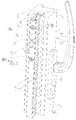
- FIG. 1 1 shows a sliding leaf 2 with a sliding leaf frame 3, on which a sliding leaf driving rail 4 in a U-profile 5 of the sliding leaf frame 3, a ventilation profile 6 and a rosette 8 of a drive device 9 (FIG. Figures 3 . 4 and 5 ) are arranged with a handle 10.
- the fixed frame is 1, its front vertical spar is 1a, see.
- FIGS. 6 The sash 3 has an upright vertical spar 3a. At him the ventilation device is to be arranged.
- the ventilation device has a vertical ventilation profile 6, which is provided with a plurality of ventilation openings, eg many parallel ventilation slots.
- the U-profile 5 and guided therein sliding sash drive rail 4 of the ventilation device can be assigned functionally, but not if the ventilation profile is a retrofit component. It then uses the components 5/4 already present on the sliding sash.
- the ventilation profile 6 of the ventilation device is designed as a separate component and has a ventilation profile-drive rail 7, which is bolted to the sliding leaf drive rail 4 via bolted 12 'stud bolts 12 (in the sense of spacers). Both drive rails 4/7 are displaceable together in the longitudinal direction. Each is guided in the assigned her profile, drive rail 4 the U-profile 5 of the movable wing, drive rail 7 the ventilation profile. 6
- the profiles 6/5 are connected by screws 11. These engage through screw openings 11a, 11b. These are in pairs adjacent to openings 16, 16a for locking pin.
- Corresponding longitudinal slots 6a, 5a are provided in the profiles, along which the stud bolts 12 (with their screw 12 ') are movable, while the drive rails 4, 7, which are coupled by means of these bolts, move in the longitudinal direction (controlled from the drive 9).
- the ventilation profile 6 has as side vents, e.g. Ventilation slots 14 which extend parallel and horizontally on the side webs of the ventilation profile 6 and allow air exchange between the outside and inside of the sash (and the window) when the ventilation device is open.
- side vents e.g. Ventilation slots 14 which extend parallel and horizontally on the side webs of the ventilation profile 6 and allow air exchange between the outside and inside of the sash (and the window) when the ventilation device is open.
- FIG. 1 an opening 16 is shown, through which a locking pin 18 engages, which engages on a bottom 30 of a fixed frame groove 20 (cf. FIGS. 4 ) is to be attached.
- a bolt shoulder (a 18a or one of two lugs 18a, 18b) of the locking pin 18.
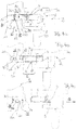
- FIG. 2 shows the embodiment of FIG. 1 in the open (fully released) position of the sliding leaf, wherein the locking pin 18 has come out of the opening 16 after the sliding panel has been moved from the ventilation position to the "open position", which can be seen in the position of the handle 10 (the Screws 11 are present but not shown).
- FIG. 3 shows an exploded view of the U-section 5 and the ventilation profile 6, wherein the drive rails 4.7 are to be connected to each other via the stud bolts 12. This ensures that during a movement of the sliding leaf drive rail. 4 is carried along by the drive device 9, the ventilation profile-drive rail 7, guided in the ventilation profile 6 (at the front, facing the frame bottom).
- the permanently held distance of the drive rails 4/5 corresponds approximately to the height of the long legs of the ventilation profile 6. He is certainly greater than the legs of the U-profile. 5
- FIGS. 4a to 4c each show sections through the fixed frame 22 with a fixed frame leg 23 (corresponds to 1a), in which a Festrahmennut 20 is provided, and the sliding sash frame 3 with the rosette 8 and the handle 10 (the latter in plan view).
- FIG. 4A shows the position of the fixed frame 22 with respect to the sliding sash frame 3 in the position in which the drive rail 7 engages the ventilation profile 6 behind a locking lug 26 of a locking pin 28 (corresponds to 18).
- One or more (short) locking pins 28 are respectively fixed to the bottom 30 of the fixed frame groove 20 and have in the embodiment of FIGS. 4a to 4c only one respective bolt shoulder 26, which is arranged at a distance from the bottom 30 of the fixed frame groove 20, that, as in FIG. 4a is shown, the sliding leaf in the closed position, when the drive rail 7 engages the ventilation profile 6 behind the locking lug 26 of the locking pin 28. An edge of a window is then close to the edge of the vertical spar 1a of the fixed frame.
- the further outboard latches 34 have such a distance from the bottom 30 of the Festrahmennut 20 that, as in FIG. 4b shown, the sliding sash frame 3 is locked in a position in which the ventilation profile 6 between the fixed frame 22 and the sliding sash frame 3 and thus allows an exchange of air through the ventilation openings 14 when the ventilation profile-driving rail 7 engages behind the locking lug 34 of the locking pin 32.
- FIGS. 4 Although in the embodiment of FIGS. 4 two different length locking pins 28 and 32 are shown, and uniform locking pins can be used in which the locking lugs 26 and 34 are combined on a locking pin.
- FIGS. 5a to 5c show a further embodiment, wherein uniform locking pins 36 are each provided with two locking lugs 38, 40 on the same locking pin.
- the locking lug 40 has such a distance from the bottom 30 of the fixed frame groove 20, that the sliding sash frame 3 is in the closed position when the drive rail 4 (of the U-profile) engages behind the locking projection 40.
- the distance between the locking projection 38 and the bottom 30 of the fixed frame groove 20 is dimensioned accordingly.
- FIG. 5c again shows the state in which the fixed frame 20 and the sliding sash frame 3 are completely separated from each other, wherein the ventilation profile 6 protrudes from the sliding sash frame 3 and the pin 36 projects slightly beyond the Festrahmennut 20.
Description
Die Erfindung betrifft eine Schiebetür oder ein Schiebefenster mit einem Schiebeflügel und einem Festrahmen mit einem aufrecht ausgerichteten Rahmenschenkel, an welchem der Schiebeflügel in seiner Schließstellung anliegt, wobei eine Lüftungsvorrichtung ein Lüftungsprofil aufweist.The invention relates to a sliding door or a sliding window with a sliding leaf and a fixed frame with a upright frame leg, on which the sliding leaf rests in its closed position, wherein a ventilation device has a ventilation profile.
Eine Lüftungsvorrichtung für Schiebetüren ist aus der
In EP'856 (GU) wird die Schiebetür mittels eines teleskopartig verstellbaren Elements am Festrahmen in eine bezüglich des Rahmenschenkels verschobene, verriegelbare Lüftungsstellung gebracht. Der Rahmenschenkel hat ein in Verschieberichtung der Schiebetür ein Stück weit ausziehbares, das teleskopartig verstellbare Element bildendes Lüftungsprofil, und das Lüftungsprofil kann quer zu dessen Verschieberichtung von Luft durchströmt werden.In EP'856 (GU), the sliding door is moved by means of a telescopically adjustable element on the fixed frame into a lockable ventilation position displaced with respect to the frame leg. The frame leg has a in the direction of displacement of the sliding door a piece extensible, the telescopically adjustable element forming ventilation profile, and the ventilation profile can be traversed transversely to the direction of displacement of air.
Das Lüftungsprofil ist also am Rahmenschenkel verschieblich gelagert, wobei das Lüftungsprofil entweder in den Festrahmenschenkel integriert oder auf den Festrahmenschenkel aufgesetzt ist. Die Verschieberichtung in die Lüftungsstellung entspricht dabei der Öffnungsrichtung der Schiebetür. Befindet sich das Lüftungsprofil in seiner teleskopisch eingeschobenen Stellung, wird es nicht von Luft durchströmt. Das Lüftungsprofil ist vollständig vom Festrahmen-Schenkel aufgenommen (vollständig von diesem verdeckt). Aufgrund des teleskopartigen Aufbaus wird ein großer Bauraum im oder am Festrahmen benötigt.The ventilation profile is thus displaceably mounted on the frame legs, wherein the ventilation profile is integrated either in the fixed frame leg or placed on the fixed frame leg. The displacement direction in the ventilation position corresponds to the opening direction of the sliding door. If the ventilation profile is in its telescopically inserted position, air will not flow through it. The ventilation profile is completely absorbed by the fixed frame leg (completely covered by the fixed frame leg). Due to the telescopic structure a large space in or on the fixed frame is needed.
Der Erfindung liegt die Aufgabe zugrunde für eine Schiebetür oder ein Schiebefenster eine in ihrer Bauart und auch in der Verbauung am Schiebeflügel einfache und platzsparende Lüftungsvorrichtungen bereitzustellen, die sich beim Betätigen des Schiebeflügels ohne weitere Betätigungsgriffe in Funktion setzen lässt. Ferner soll ein Beschlag sowie eine Schiebetür oder ein Schiebefenster zur Verfügung gestellt werden, wobei die Lüftungsvorrichtung eingesetzt wird.The invention has for its object for a sliding door or a sliding window to provide a simple and space-saving ventilation devices in their design and also in the obstruction on the sliding sash, which can be put into operation of the sliding sash without further operating handles in function. Furthermore, should a fitting and a sliding door or a sliding window are provided, wherein the ventilation device is used.
Diese Aufgabe wird mit einer Schiebetür oder einem Schiebefenster mit den Merkmalen des Anspruches 1 sowie einem Verfahren mit den Merkmalen des Anspruches 10 gelöst.This object is achieved with a sliding door or a sliding window with the features of claim 1 and a method having the features of
Die erfindungsgemäße Lüftungsvorrichtung ist für eine Schiebetür oder ein Schiebefenster mit einem Schiebeflügel angepasst und vorgesehen, der mit einem Festrahmen über einen aufrecht (sinngemäß im Wesentlichen vertikal) ausgerichteten Rahmenschenkel zusammenwirkt. An dem Schenkel liegt der Schiebeflügel in seiner Schließstellung an. Ein Lüftungsprofil ist vorgesehen, welches so ausgebildet ist, dass es in einer Lüftungsstellung des Schiebeflügels einen Zwischenraum zwischen dem Schiebeflügel und dem Festrahmen (seinem aufrechten Holm) schließt und in der Schließstellung des Schiebeflügels in den Festrahmen eingeführt wird. Das Profil ist mit dem Schiebeflügel verbindbar und mit diesem bewegbar, wobei die Lüftungsvorrichtung zumindest einen Riegelzapfen aufweist, der zum Verriegeln des Schiebeflügels mit dem Festrahmen in der Lüftungsstellung sowie in der Schließstellung des Schiebeflügels ausgebildet, angepasst und geeignet ist.The ventilation device according to the invention is adapted and provided for a sliding door or sliding window with a sliding leaf, which cooperates with a fixed frame via an upright (mutually substantially vertically) aligned frame legs. On the leg of the sliding panel is in its closed position. A ventilation profile is provided, which is designed so that it closes a gap between the sliding leaf and the fixed frame (its upright spar) in a ventilation position of the sliding leaf and is inserted in the closed position of the sliding leaf in the fixed frame. The profile is connectable to the sliding leaf and movable therewith, wherein the ventilation device has at least one locking pin, which is designed, adapted and suitable for locking the sliding leaf with the fixed frame in the ventilation position and in the closed position of the sliding leaf.
Bei der Erfindung ist es möglich, dass beim Schließen des Schiebeflügels das Lüftungsprofil in eine Nut im Festrahmen einfährt und damit im geschlossenen Zustand des Schiebeflügels nicht sichtbar ist.In the invention, it is possible that when closing the sliding sash, the ventilation profile enters a groove in the fixed frame and thus is not visible in the closed state of the sliding sash.
Beim Betätigen des Schiebeflügels in die Öffnungsrichtung wird das Lüftungsprofil wieder aus der Nut des Festrahmens herausgefahren, ohne dass zusätzliche Maßnahmen erforderlich wären.When the sliding sash is moved in the opening direction, the ventilation profile is moved out of the groove of the fixed frame without any additional measures being required.
Es sind also keine zusätzlichen Maßnahmen erforderlich, das Lüftungsprofil beim Öffnen und Schließen des Schiebeflügels aufwärts bzw. abwärts zu bewegen, um damit eine Verriegelung der Schiebeflügel-Treibschiene mit zugehörigen Verriegelungselementen an dem Festrahmen zu erreichen.So there are no additional measures required to move the ventilation profile when opening and closing the sliding leaf upwards or downwards, so as to achieve a locking of the sliding leaf driving rail with associated locking elements on the fixed frame.
Die Erfindung bietet ein schmal bauendes und damit platzsparendes Lüftungsprofil. Es hat den Vorteil, dass die Verminderung des Festrahmen-Querschnitts durch den - für das einfahrende Lüftungsprofil erforderlichen - Platz kleiner gehalten werden kann als bei
Bei einer vorteilhaften Ausgestaltung der Lüftungsvorrichtung, bei der an dem Schiebeflügel eine Schiebeflügel-Treibschiene zum Verriegeln und Entriegeln des Schiebeflügels vorgesehen ist, hat das Lüftungsprofil eine Lüftungsprofil-Treibschiene, die so ausgeführt ist, dass sie mit der Schiebeflügel-Treibschiene zu verschrauben ist.In an advantageous embodiment of the ventilation device, in which a sliding leaf driving rail for locking and unlocking the sliding leaf is provided on the sliding leaf, the ventilation profile has a ventilation profile driving rail, which is designed so that it is to be screwed to the sliding leaf driving rail.
Wenn bei der beanspruchten Lüftungsvorrichtung das Lüftungsprofil als eigenständiges Lüftungsprofil ausgeführt ist und eine Lüftungsprofil-Treibschiene aufweist, die mit der Schiebeflügel-Treibschiene verschraubt ist, kann die Lüftungsvorrichtung auch als Nachrüstprodukt eingesetzt werden. Das Lüftungsprofil ist dazu auf das vorhandene Bauteil (die Schiebeflügel-Treibschiene) aufzusetzen.If in the claimed ventilation device, the ventilation profile is designed as a self-contained ventilation profile and has a ventilation profile-drive rail, which is bolted to the sliding leaf driving rail, the ventilation device can also be used as a retrofit product. The ventilation profile is to be placed on the existing component (the sliding leaf drive rail).
Eine weitere vorteilhafte Ausgestaltung ist dadurch gekennzeichnet, dass die Lüftungsprofil-Treibschiene zum Verriegeln des Schiebeflügels in der Lüftungsstellung im vorderen Bereich des Lüftungsprofils angeordnet ist. Es wird damit erreicht, dass die Lüftungsvorrichtung sowohl in der Schließstellung des Schiebeflügels als auch in der Lüftungsstellung des Schiebeflügels ohne weitere Bauteile sicher verriegelt werden kann, indem die Schiebeflügel-Treibschiene bzw. die Lüftungsprofil-Treibschiene hinter entsprechende Verriegelungsansätze der Riegelzapfen greift.A further advantageous embodiment is characterized in that the ventilation profile drive rail is arranged for locking the sliding leaf in the ventilation position in the front region of the ventilation profile. It is thus achieved that the ventilation device can be securely locked without further components both in the closed position of the sliding leaf and in the ventilation position of the sliding leaf by the sliding leaf driving rail or the ventilation profile drive rail engages behind corresponding locking lugs of the locking pin.
In einer weiteren vorteilhaften Ausgestaltung haben der oder die Riegelzapfen eine solche Länge, dass sie mit einer am Festrahmen zur Aufnahme des Lüftungsprofils in der Schließstellung des Schiebeflügels vorgesehenen (vertikalen) Festrahmennut bündig sind. Dadurch, dass die Riegelzapfen mit der Festrahmennut bündig ausgeführt sind, wird vorteilhaft erreicht, dass die/der Riegelzapfen bei geöffnetem Schiebeflügel nicht störend in Erscheinung treten/tritt.In a further advantageous embodiment, the one or more locking pins have a length such that they are flush with a provided on the fixed frame for receiving the ventilation profile in the closed position of the sliding sash (vertical) Festrahmennut. The fact that the locking pins are made flush with the Festrahmennut, is advantageously achieved that the / the locking pin with open sliding sash does not interfere in appearance / occurs.
Außerdem wird eine Beschädigung des oder der Riegelzapfen(s) vermieden, die auftreten könnte, wenn Riegelzapfen über den Festrahmen hinaus vorstehen würden.In addition, damage to the one or more locking pin (s) is avoided, which could occur if locking pins would protrude beyond the fixed frame addition.
In einer weiteren vorteilhaften Ausgestaltung haben zumindest zwei Riegelzapfen unterschiedliche Längen und damit weisen Verriegelungsansätze an den Riegelzapfen verschiedene Abstände zu den Montagestellen an dem Festrahmen auf. Einer oder mehrere (kürzere) Riegelzapfen sind zum Verriegeln des Schiebeflügels mit dem Festrahmen in der Schließstellung des Schiebeflügels und einer oder mehrere (längere) Riegelzapfen sind zum Verriegeln des Schiebeflügels mit dem Festrahmen in der Lüftungsstellung des Schiebeflügels angepasst. Indem die Riegelzapfen verschiedene Längen haben, erreicht die eine Gruppe von Riegelzapfen das Verriegeln des Schiebeflügels in der Schließstellung (Verriegelung zwischen der Schiebeflügel-Treibschiene und Verriegelungsansatz des Riegelzapfens) bzw. erreicht die andere Gruppe eine Verriegelung des Schiebeflügels in der Lüftungsstellung (Verriegelung der Lüftungs-Treibschiene mit dem Verriegelungsansatz des Riegelzapfens). Eine "Gruppe" ist insoweit auch ein einziger Riegelzapfen.In a further advantageous embodiment, at least two locking pins have different lengths and thus have locking lugs on the locking pin different distances to the mounting points on the fixed frame. One or more (shorter) locking pins are adapted for locking the sliding leaf with the fixed frame in the closed position of the sliding leaf and one or more (longer) locking pins are adapted for locking the sliding leaf with the fixed frame in the ventilation position of the sliding leaf. By the locking pins have different lengths, the one group of locking pins reaches the locking of the sliding leaf in the closed position (locking between the sliding leaf driving rail and locking approach of the bolt) and reaches the other Group a locking of the sliding leaf in the ventilation position (locking the ventilation drive rail with the locking lug of the locking pin). A "group" is in this respect also a single locking pin.
In einer weiteren vorteilhaften Ausgestaltung haben zumindest zwei Riegelzapfen die gleiche Länge, jedoch je zwei Riegelansätze, wobei die Riegelzapfen sowohl zum Verriegeln des Schiebeflügels mit dem Festrahmen in der Schließstellung des Schiebeflügels als auch zum Verriegeln des Schiebeflügels mit dem Festrahmen in der Lüftungsstellung des Schiebeflügels angepasst sind. Dies hat den Vorteil, dass nur eine Art von Riegelzapfen benötigt wird, um sowohl die Verriegelung des Schiebeflügels in der Schließstellung als auch in der Lüftungsstellung zu erreichen. Der Abstand des einen, inneren Riegelansatzes nahe bei dem Boden der Festrahmennut ist so bemessen, dass bei einer Verriegelung der Lüftungsprofil-Treibschiene hinter diesem Riegelansatz der Schiebeflügel in der Schließstellung fixiert ist. Der äußere Riegelansatz hat von dem Boden der Festrahmennut einen solchen Abstand, dass der Schiebeflügel in der Lüftungsstellung fixiert ist, wenn die Lüftungs-Treibschiene den äußeren Riegelzapfenansatz hintergreift.In a further advantageous embodiment, at least two locking pins have the same length, but two bolt approaches, the locking pins are adapted both for locking the sliding leaf with the fixed frame in the closed position of the sliding leaf and for locking the sliding leaf with the fixed frame in the ventilation position of the sliding leaf , This has the advantage that only one type of locking pin is needed to achieve both the locking of the sliding leaf in the closed position and in the ventilation position. The distance between the one, inner locking lug near the bottom of the Festrahmennut is dimensioned so that is fixed at a locking of the ventilation profile-drive rail behind this locking lug of the sliding leaf in the closed position. The outer locking lug has such a distance from the bottom of the Festrahmennut that the sliding sash is fixed in the ventilation position when the ventilation drive rail engages behind the outer locking lug approach.
Vorzugsweise wird auch einen Beschlag für einen Schiebeflügel einer Schiebetür oder eines Schiebefensters vorgesehen. Der Beschlag hat eine Antriebsvorrichtung und eine Schiebeflügel-Treibschiene sowie eine Lüftungsvorrichtung.Preferably, a fitting for a sliding leaf of a sliding door or a sliding window is also provided. The fitting has a drive device and a sliding leaf drive rail and a ventilation device.
Die Lüftungsvorrichtung ist langgestreckt, wobei die Höhe des Schiebeflügels die Länge in vertikaler Richtung vorgibt.The ventilation device is elongated, wherein the height of the sliding sash dictates the length in the vertical direction.
Ausführungsbeispiele der Erfindung werden nun anhand der Zeichnungen beschrieben.
-
Fig. 1 zeigt einen Abschnitt des Schiebeflügelrahmens, wobei sich derSchiebeflügel 2 in der Schließstellung befindet. -
Fig. 2 zeigt den Abschnitt des Schiebeflügelrahmens, wobei sich derSchiebeflügel 2 in der geöffneten Stellung befindet. -
Fig. 3 zeigt eine Explosionsdarstellung eines U-Profils 5 für den Schiebeflügel und einesLüftungsprofils 6 mit den Verbindungs- und Abstands-Haltestücken 12 (als Befestigungsmittel) zwischen diesen Bauteilen. -
Fig. 4a zeigt eine Detailansicht des Schiebeflügelrahmens und des Festrahmens im horizontalen Schnitt, wobei derSchiebeflügel 2 in seiner Schließstellung fixiert ist. -
Fig. 4b zeigt den Schiebeflügel und den Festrahmen im horizontalen Schnitt, wobei der Schiebeflügel sich in einer Lüftungsstellung befindet (Spaltbreite L). -
Fig. 4c zeigt den Schiebeflügel und den Festrahmen im Schnitt, wobei derSchiebeflügel 2 zum weiteren Öffnen desselben völlig freigegeben ist. Die Fahrtrichtung ist S zum Öffnen. -
Fig. 5a zeigt eine alternative Detailansicht des Schiebeflügelrahmens und des Festrahmens im Schnitt, wobei der Schiebeflügel in seiner Schließstellung fixiert ist. -
Fig. 5b zeigt den Schiebeflügel und den Festrahmen im Schnitt, wobei der Schiebeflügel sich in der Lüftungsstellung befindet. -
Fig. 5c zeigt den Schiebeflügel und den Festrahmen im Schnitt, wobei der Schiebeflügel zum weiteren Öffnen S desselben völlig freigegeben ist. -
Fig. 6a und 6b zeigen den Schiebeflügel und den Festrahmen in zwei Stellungen, Schließstellung und Lüftungsstellung, wobei dasLüftungsprofil 6 am vertikalen Holm des Schiebeflügels angeordnet ist (und relativ zum vertikalen Schenkel des Festrahmens verfahrbar ist).
-
Fig. 1 shows a portion of the sliding sash frame, wherein thesliding sash 2 is in the closed position. -
Fig. 2 shows the portion of the sliding sash frame with the slidingsash 2 in the open position. -
Fig. 3 shows an exploded view of a U-profile 5 for the sliding leaf and aventilation profile 6 with the connecting and spacing holding pieces 12 (as a fastener) between these components. -
Fig. 4a shows a detailed view of the sliding sash frame and the fixed frame in horizontal section, wherein the slidingsash 2 is fixed in its closed position. -
Fig. 4b shows the sliding leaf and the fixed frame in horizontal section, with the sliding leaf is in a ventilation position (gap width L). -
Fig. 4c shows the sliding sash and the fixed frame in section, the slidingsash 2 is fully released to further open it. The direction of travel is S for opening. -
Fig. 5a shows an alternative detailed view of the sliding sash frame and the fixed frame in section, wherein the sliding sash is fixed in its closed position. -
Fig. 5b shows the sliding leaf and the fixed frame in section, with the sliding leaf is in the ventilation position. -
Fig. 5c shows the sliding sash and the fixed frame in section, the sliding sash is fully released for further opening S thereof. -
Fig. 6a and 6b show the sliding leaf and the fixed frame in two positions, closed position and ventilation position, wherein theventilation profile 6 is arranged on the vertical spar of the sliding leaf (and relative to the vertical leg of the fixed frame is movable).
Die Lüftungsvorrichtung hat ein vertikales Lüftungsprofil 6, das mit einer Vielzahl von Lüftungsöffnungen, z.B. vielen parallel verlaufenden Lüftungsschlitzen versehen ist. An sich kann auch das U-Profil 5 und die darin geführte Schiebeflügel-Treibschiene 4 der Lüftungsvorrichtung funktionell zugeordnet werden, nur dann nicht, wenn das Lüftungsprofil ein Nachrüstbauteil ist. Es verwendet dann die schon am Schiebeflügel vorhandenen Bauteile 5/4 mit.The ventilation device has a
Das Lüftungsprofil 6 der Lüftungsvorrichtung ist als separates Bauteil ausgebildet und hat eine Lüftungsprofil-Treibschiene 7, die mit der Schiebeflügel-Treibschiene 4 über angeschraubte 12' Stehbolzen 12 (im Sinne von Abstandshaltern) verschraubt ist. Beide Treibschienen 4/7 sind gemeinsam in Längsrichtung verschiebbar. Jede ist in dem ihr zugewiesenen Profil geführt, Treibschiene 4 dem U-Profil 5 des bewegbaren Flügels, Treibschiene 7 dem Lüftungsprofil 6.The
Die Profile 6/5 werden durch Schrauben 11 miteinander verbunden. Diese greifen durch Schrauböffnungen 11a, 11b. Diese sind paarweise benachbart zu Öffnungen 16, 16a für Riegelzapfen.The
In den Profilen sind korrespondierende Längsschlitze 6a, 5a (oder 6b, 5b) vorgesehen, entlang denen die Stehbolzen 12 (mit ihrer Verschraubung 12') bewegbar sind, während die über diese Bolzen bewegungs-gekoppelten Treibschienen 4,7 sich in Längsrichtung bewegen (gesteuert vom Antrieb 9).Corresponding longitudinal slots 6a, 5a (or 6b, 5b) are provided in the profiles, along which the stud bolts 12 (with their screw 12 ') are movable, while the drive rails 4, 7, which are coupled by means of these bolts, move in the longitudinal direction (controlled from the drive 9).
Das Lüftungsprofil 6 hat als seitliche Lüftungsöffnungen z.B. Lüftungsschlitze 14, die sich parallel und horizontal an den Seitenstegen des Lüftungsprofils 6 erstrecken und bei geöffneter Lüftungsvorrichtung einen Luftaustausch zwischen Außenseite und Innenseite des Schiebeflügels (und des Fensters) zulassen.The
In
Der dauerhaft gehaltene Abstand der Treibschienen 4/5 entspricht in etwa der Höhe der langen Schenkel des Lüftungsprofils 6. Er ist jedenfalls größer als die Schenkel des U-Profils 5.The permanently held distance of the drive rails 4/5 corresponds approximately to the height of the long legs of the
Die
Einer oder mehrere (kurze) Riegelzapfen 28 sind jeweils am Boden 30 der Festrahmennut 20 befestigt und haben bei dem Ausführungsbeispiel der
Bei dem Ausführungsbeispiel gemäß den
Obwohl in dem Ausführungsbeispiel der
Die
Wie in
Obwohl bei dem Ausführungsbeispiel der
Claims (12)
- A sliding door or sliding window, comprising a sliding sash (2) and a fixed frame (22), wherein the sliding sash (2) interacts with an upright oriented fixed frame leg (23), on which the sliding sash (2) rests in its closed position, wherein a ventilation apparatus comprises a ventilation profile (6), which ventilation profile is structured and formed in such a way that- in a ventilation position of the sliding sash (2) it closes an intermediate space between the sliding sash (2) and the fixed frame (22), and can be inserted into the fixed frame (22) in the closed position of the sliding sash (2);- it is connected to the sliding sash (2) and can be moved therewith, wherein the ventilation apparatus comprises at least one locking pin (18; 28; 32; 36), which is adapted and capable of locking the sliding sash (2) to the fixed frame (22) in the ventilation position and in the closed position of the sliding sash (2).
- A sliding door or sliding window according to claim 1, comprising a sliding-sash drive rail (4) for the sliding sash (2) for locking and unlocking the sliding sash (2), wherein the ventilation profile (6) comprises a ventilation-profile drive rail (7), which can be screwed together with the sliding-sash drive rail (4) by maintaining a distance.
- A sliding door or sliding window according to claim 1, wherein the ventilation-profile drive rail (7) is arranged in the front region of the ventilation profile (6) for locking the sliding sash (2) in the ventilation position.
- A sliding door or sliding window according to claim 1, wherein the at least one locking pin (18; 28; 32; 36) has such a length so as to be flush with or terminate a fixed frame groove (20) provided on the fixed frame (22; 23) for accommodating the ventilation profile (6) in the closed position of the sliding sash (2).
- A sliding door or sliding window according to claim 1, wherein at least two locking pins (28; 32) have a different length, so that locking lugs (26; 34) on the locking pins (28; 32) can have different distances from mounting positions on a bottom (30) of the fixed frame groove (20), especially at least one locking pin (28) is adapted for locking the sliding sash (2) to the fixed frame (22) in the closed position of the sliding sash (2) and at least one locking pin (32) for locking the sliding sash (2) to the fixed frame (22) in the ventilation position of the sliding sash (2).
- A sliding door or sliding window according to claim 1, wherein at least two locking pins (36) have the same length, but each comprise two locking lugs (38, 40), and the locking pins (36) are adapted both for locking the sliding sash (2) to the fixed frame (22) in the closed position of the sliding sash (2) and also for locking the sliding sash (2) to the fixed frame (22) in the ventilation position of the sliding sash (2).
- A sliding door or sliding window according to one of the claims 1 to 6, wherein the sliding sash (2) comprises a fitting which comprises a drive apparatus (9) for a sliding-sash drive rail (4) of the ventilation apparatus.
- A sliding door or sliding window according to one of the preceding claims,
wherein the elongated ventilation apparatus comprises a ventilation profile (6) and a U-profile (5) for the sliding sash, as well as two drive rails (4, 7) which are held spaced from each other or at a defined distance (12) and are guided parallel in the profiles (5, 6),- wherein the ventilation profile (6) comprises ventilation openings (14);- wherein the ventilation apparatus comprises at least one locking pin (18; 28; 32; 36), which are adapted and capable for locking with the one or the other drive rail (4, 7) in a ventilation position or a closed position (of the ventilation apparatus). - A sliding door or sliding window according to one of the preceding claims,
wherein the elongated ventilation apparatus comprises a ventilation profile (6) and a drive rail (7) which is guided therein,- which ventilation profile (6) comprises lateral ventilation openings (14);- wherein the guided drive rail (7) is adapted to be connected via spacers (12) in a spaced manner to another drive rail (4) on the sliding sash in order to be jointly movable in the longitudinal direction, and the guided drive rail (7) is similarly adapted and capable of interacting with at least one locking pin (18; 28; 32; 36) for locking in a ventilation position or closed position of the ventilation apparatus. - A method for a sliding door or a sliding window, comprising a sliding sash (2) which interacts with a fixed frame (22) with an upright oriented fixed frame leg (23), on which the sliding sash (2) rests in its closed position, wherein a ventilation apparatus comprises a ventilation profile (6) and at least one locking pin, which ventilation profile (6)- in a ventilation position of the sliding sash closes an intermediate space between the sliding sash (2) and the upright leg (23) of the fixed frame (22), and is inserted in the closed position of the sliding sash into the upright leg (23) of the fixed frame (22);- is connected to the sliding sash (2) and is moved with said sash (2), wherein the locking pin (18; 28; 32; 36) of the ventilation apparatus locks the sliding sash (2) to the fixed frame (22) via its upright leg (23) in the ventilation position and also in the closed position of the sliding sash.
- A method according to claim 10, wherein the one or several locking pins (36) have the same length, but each comprise two locking lugs (38, 40), and the locking pins (36) are adapted both for locking the sliding sash (2) to the fixed frame (22) in the closed position of the sliding sash (2) and also for locking the sliding sash (2) to the fixed frame (22) in the ventilation position of the sliding sash (2).
- A method according to claim 10, wherein the ventilation profile (6), which is retained on the sliding sash, travels into a groove (20) in the vertical leg (23) of the fixed frame (22) during closure of the sliding sash (2), as a result of which the profile (6) is not visible in the closed state of the sliding sash.
Priority Applications (1)
| Application Number | Priority Date | Filing Date | Title |
|---|---|---|---|
| PL12186905T PL2574716T3 (en) | 2011-10-01 | 2012-10-01 | Sliding door or window with a ventilation unit and mode of operation |
Applications Claiming Priority (1)
| Application Number | Priority Date | Filing Date | Title |
|---|---|---|---|
| DE102011054130A DE102011054130A1 (en) | 2011-10-01 | 2011-10-01 | Narrow ventilation device for a sliding leaf |
Publications (3)
| Publication Number | Publication Date |
|---|---|
| EP2574716A2 EP2574716A2 (en) | 2013-04-03 |
| EP2574716A3 EP2574716A3 (en) | 2015-02-25 |
| EP2574716B1 true EP2574716B1 (en) | 2016-03-09 |
Family
ID=47172273
Family Applications (1)
| Application Number | Title | Priority Date | Filing Date |
|---|---|---|---|
| EP12186905.1A Active EP2574716B1 (en) | 2011-10-01 | 2012-10-01 | Sliding door or window with a ventilation unit and mode of operation |
Country Status (3)
| Country | Link |
|---|---|
| EP (1) | EP2574716B1 (en) |
| DE (1) | DE102011054130A1 (en) |
| PL (1) | PL2574716T3 (en) |
Families Citing this family (1)
| Publication number | Priority date | Publication date | Assignee | Title |
|---|---|---|---|---|
| EP2876235A1 (en) * | 2013-11-21 | 2015-05-27 | Lock Industry Domus Security S.A. | Lock assembly for sliding doors and windows |
Family Cites Families (4)
| Publication number | Priority date | Publication date | Assignee | Title |
|---|---|---|---|---|
| DE2061790C3 (en) * | 1970-12-15 | 1979-12-13 | N.V. Metaalindustrie Heycop, Utrecht (Niederlande) | Ventilation device for windows, doors or the like |
| GB8507074D0 (en) * | 1985-03-19 | 1985-04-24 | Parkes Josiah & Sons Ltd | Fastening mechanism |
| FR2729177B1 (en) * | 1995-01-10 | 1997-03-28 | Mandojana Jean Claude | CLOSING SECURITY DEVICE FOR SLIDING WINDOWS, DOORS AND WINDOW WINDOWS |
| DE202007011762U1 (en) | 2007-08-16 | 2008-12-24 | Gretsch-Unitas GmbH Baubeschläge | breather |
-
2011
- 2011-10-01 DE DE102011054130A patent/DE102011054130A1/en not_active Withdrawn
-
2012
- 2012-10-01 PL PL12186905T patent/PL2574716T3/en unknown
- 2012-10-01 EP EP12186905.1A patent/EP2574716B1/en active Active
Also Published As
| Publication number | Publication date |
|---|---|
| EP2574716A2 (en) | 2013-04-03 |
| DE102011054130A1 (en) | 2013-04-04 |
| PL2574716T3 (en) | 2016-08-31 |
| EP2574716A3 (en) | 2015-02-25 |
Similar Documents
| Publication | Publication Date | Title |
|---|---|---|
| DE102012017948B3 (en) | Method and arrangement for attaching a post to a frame strip of a window or a door by means of a post connector | |
| DE102017110286A1 (en) | Frame for a drawer | |
| DE102011011113B4 (en) | Frame system of a particle protection grid | |
| DE102016119515A1 (en) | Sliding door fitting, sliding door unit, method for opening a sliding door, and method for closing a sliding door | |
| EP0718456A1 (en) | Closing device for window, door and the like | |
| EP3045638A1 (en) | Sliding and rotating leaf system | |
| WO2015192154A1 (en) | Drawer | |
| EP2574716B1 (en) | Sliding door or window with a ventilation unit and mode of operation | |
| DE202007011076U1 (en) | Band arrangement with guide profile | |
| EP3859107B1 (en) | Sliding door | |
| EP3192951B1 (en) | Fitting for a sliding door, sliding door unit, method for opening a sliding door and method for closing a sliding door | |
| DE102012200430B4 (en) | Sliding-door or window system with at least two designed as a door or window sliding elements and locking device therefor | |
| DE202015100014U1 (en) | Locking device of a double-sided pull-out drawer cabinet | |
| EP3798390B1 (en) | Folding installation | |
| DE102013017770A1 (en) | Furniture, with at least one drawer-like pull-out part | |
| EP3327228B1 (en) | Locking device for locking and transport of at least two mounted plate-shaped elements which can be moved along a first direction and an opposing second direction and wall assembly with at least two panel-shaped elements | |
| EP3715578A1 (en) | Insect proof door | |
| EP3444417B1 (en) | Load system for building openings | |
| DE202013004939U1 (en) | Device for positioning and fixing a movable furniture part | |
| DE102016216835B4 (en) | Lift-out protection for a sliding and liftable wing | |
| DE102008059319A1 (en) | Sliding door has two door leaves that are arranged on guide rail in moving manner, where door leaves are connected by coupling units in closed position in detached manner, where upright frame profiles are meshed with each other | |
| EP2791443B1 (en) | Furniture with a pull-out stop for drawers | |
| EP4039925A1 (en) | Wing assembly | |
| EP2669462A1 (en) | Holding device for venetian blinds | |
| AT413725B (en) | Device for attaching load to window or door, has mounting plate fastened to load, where loading band is fastened in adjusting positions |
Legal Events
| Date | Code | Title | Description |
|---|---|---|---|
| PUAI | Public reference made under article 153(3) epc to a published international application that has entered the european phase |
Free format text: ORIGINAL CODE: 0009012 |
|
| AK | Designated contracting states |
Kind code of ref document: A2 Designated state(s): AL AT BE BG CH CY CZ DE DK EE ES FI FR GB GR HR HU IE IS IT LI LT LU LV MC MK MT NL NO PL PT RO RS SE SI SK SM TR |
|
| AX | Request for extension of the european patent |
Extension state: BA ME |
|
| PUAL | Search report despatched |
Free format text: ORIGINAL CODE: 0009013 |
|
| AK | Designated contracting states |
Kind code of ref document: A3 Designated state(s): AL AT BE BG CH CY CZ DE DK EE ES FI FR GB GR HR HU IE IS IT LI LT LU LV MC MK MT NL NO PL PT RO RS SE SI SK SM TR |
|
| AX | Request for extension of the european patent |
Extension state: BA ME |
|
| RIC1 | Information provided on ipc code assigned before grant |
Ipc: E05B 65/08 20060101ALI20150116BHEP Ipc: E06B 7/02 20060101AFI20150116BHEP |
|
| 17P | Request for examination filed |
Effective date: 20150428 |
|
| RBV | Designated contracting states (corrected) |
Designated state(s): AL AT BE BG CH CY CZ DE DK EE ES FI FR GB GR HR HU IE IS IT LI LT LU LV MC MK MT NL NO PL PT RO RS SE SI SK SM TR |
|
| GRAP | Despatch of communication of intention to grant a patent |
Free format text: ORIGINAL CODE: EPIDOSNIGR1 |
|
| INTG | Intention to grant announced |
Effective date: 20151022 |
|
| GRAS | Grant fee paid |
Free format text: ORIGINAL CODE: EPIDOSNIGR3 |
|
| GRAA | (expected) grant |
Free format text: ORIGINAL CODE: 0009210 |
|
| AK | Designated contracting states |
Kind code of ref document: B1 Designated state(s): AL AT BE BG CH CY CZ DE DK EE ES FI FR GB GR HR HU IE IS IT LI LT LU LV MC MK MT NL NO PL PT RO RS SE SI SK SM TR |
|
| REG | Reference to a national code |
Ref country code: GB Ref legal event code: FG4D Free format text: NOT ENGLISH |
|
| REG | Reference to a national code |
Ref country code: AT Ref legal event code: REF Ref document number: 779685 Country of ref document: AT Kind code of ref document: T Effective date: 20160315 Ref country code: CH Ref legal event code: EP |
|
| REG | Reference to a national code |
Ref country code: IE Ref legal event code: FG4D Free format text: LANGUAGE OF EP DOCUMENT: GERMAN |
|
| REG | Reference to a national code |
Ref country code: CH Ref legal event code: NV Representative=s name: ISLER AND PEDRAZZINI AG, CH |
|
| REG | Reference to a national code |
Ref country code: DE Ref legal event code: R096 Ref document number: 502012006209 Country of ref document: DE |
|
| REG | Reference to a national code |
Ref country code: NL Ref legal event code: FP |
|
| REG | Reference to a national code |
Ref country code: LT Ref legal event code: MG4D |
|
| PG25 | Lapsed in a contracting state [announced via postgrant information from national office to epo] |
Ref country code: FI Free format text: LAPSE BECAUSE OF FAILURE TO SUBMIT A TRANSLATION OF THE DESCRIPTION OR TO PAY THE FEE WITHIN THE PRESCRIBED TIME-LIMIT Effective date: 20160309 Ref country code: NO Free format text: LAPSE BECAUSE OF FAILURE TO SUBMIT A TRANSLATION OF THE DESCRIPTION OR TO PAY THE FEE WITHIN THE PRESCRIBED TIME-LIMIT Effective date: 20160609 Ref country code: HR Free format text: LAPSE BECAUSE OF FAILURE TO SUBMIT A TRANSLATION OF THE DESCRIPTION OR TO PAY THE FEE WITHIN THE PRESCRIBED TIME-LIMIT Effective date: 20160309 Ref country code: ES Free format text: LAPSE BECAUSE OF FAILURE TO SUBMIT A TRANSLATION OF THE DESCRIPTION OR TO PAY THE FEE WITHIN THE PRESCRIBED TIME-LIMIT Effective date: 20160309 Ref country code: GR Free format text: LAPSE BECAUSE OF FAILURE TO SUBMIT A TRANSLATION OF THE DESCRIPTION OR TO PAY THE FEE WITHIN THE PRESCRIBED TIME-LIMIT Effective date: 20160610 |
|
| PG25 | Lapsed in a contracting state [announced via postgrant information from national office to epo] |
Ref country code: RS Free format text: LAPSE BECAUSE OF FAILURE TO SUBMIT A TRANSLATION OF THE DESCRIPTION OR TO PAY THE FEE WITHIN THE PRESCRIBED TIME-LIMIT Effective date: 20160309 Ref country code: SE Free format text: LAPSE BECAUSE OF FAILURE TO SUBMIT A TRANSLATION OF THE DESCRIPTION OR TO PAY THE FEE WITHIN THE PRESCRIBED TIME-LIMIT Effective date: 20160309 Ref country code: LT Free format text: LAPSE BECAUSE OF FAILURE TO SUBMIT A TRANSLATION OF THE DESCRIPTION OR TO PAY THE FEE WITHIN THE PRESCRIBED TIME-LIMIT Effective date: 20160309 Ref country code: LV Free format text: LAPSE BECAUSE OF FAILURE TO SUBMIT A TRANSLATION OF THE DESCRIPTION OR TO PAY THE FEE WITHIN THE PRESCRIBED TIME-LIMIT Effective date: 20160309 |
|
| PG25 | Lapsed in a contracting state [announced via postgrant information from national office to epo] |
Ref country code: IS Free format text: LAPSE BECAUSE OF FAILURE TO SUBMIT A TRANSLATION OF THE DESCRIPTION OR TO PAY THE FEE WITHIN THE PRESCRIBED TIME-LIMIT Effective date: 20160709 Ref country code: EE Free format text: LAPSE BECAUSE OF FAILURE TO SUBMIT A TRANSLATION OF THE DESCRIPTION OR TO PAY THE FEE WITHIN THE PRESCRIBED TIME-LIMIT Effective date: 20160309 |
|
| PG25 | Lapsed in a contracting state [announced via postgrant information from national office to epo] |
Ref country code: SK Free format text: LAPSE BECAUSE OF FAILURE TO SUBMIT A TRANSLATION OF THE DESCRIPTION OR TO PAY THE FEE WITHIN THE PRESCRIBED TIME-LIMIT Effective date: 20160309 Ref country code: CZ Free format text: LAPSE BECAUSE OF FAILURE TO SUBMIT A TRANSLATION OF THE DESCRIPTION OR TO PAY THE FEE WITHIN THE PRESCRIBED TIME-LIMIT Effective date: 20160309 Ref country code: RO Free format text: LAPSE BECAUSE OF FAILURE TO SUBMIT A TRANSLATION OF THE DESCRIPTION OR TO PAY THE FEE WITHIN THE PRESCRIBED TIME-LIMIT Effective date: 20160309 Ref country code: SM Free format text: LAPSE BECAUSE OF FAILURE TO SUBMIT A TRANSLATION OF THE DESCRIPTION OR TO PAY THE FEE WITHIN THE PRESCRIBED TIME-LIMIT Effective date: 20160309 Ref country code: PT Free format text: LAPSE BECAUSE OF FAILURE TO SUBMIT A TRANSLATION OF THE DESCRIPTION OR TO PAY THE FEE WITHIN THE PRESCRIBED TIME-LIMIT Effective date: 20160711 |
|
| REG | Reference to a national code |
Ref country code: DE Ref legal event code: R097 Ref document number: 502012006209 Country of ref document: DE |
|
| PLBE | No opposition filed within time limit |
Free format text: ORIGINAL CODE: 0009261 |
|
| STAA | Information on the status of an ep patent application or granted ep patent |
Free format text: STATUS: NO OPPOSITION FILED WITHIN TIME LIMIT |
|
| PG25 | Lapsed in a contracting state [announced via postgrant information from national office to epo] |
Ref country code: DK Free format text: LAPSE BECAUSE OF FAILURE TO SUBMIT A TRANSLATION OF THE DESCRIPTION OR TO PAY THE FEE WITHIN THE PRESCRIBED TIME-LIMIT Effective date: 20160309 |
|
| 26N | No opposition filed |
Effective date: 20161212 |
|
| PG25 | Lapsed in a contracting state [announced via postgrant information from national office to epo] |
Ref country code: BG Free format text: LAPSE BECAUSE OF FAILURE TO SUBMIT A TRANSLATION OF THE DESCRIPTION OR TO PAY THE FEE WITHIN THE PRESCRIBED TIME-LIMIT Effective date: 20160609 |
|
| PG25 | Lapsed in a contracting state [announced via postgrant information from national office to epo] |
Ref country code: SI Free format text: LAPSE BECAUSE OF FAILURE TO SUBMIT A TRANSLATION OF THE DESCRIPTION OR TO PAY THE FEE WITHIN THE PRESCRIBED TIME-LIMIT Effective date: 20160309 |
|
| GBPC | Gb: european patent ceased through non-payment of renewal fee |
Effective date: 20161001 |
|
| REG | Reference to a national code |
Ref country code: IE Ref legal event code: MM4A |
|
| REG | Reference to a national code |
Ref country code: FR Ref legal event code: ST Effective date: 20170630 |
|
| PG25 | Lapsed in a contracting state [announced via postgrant information from national office to epo] |
Ref country code: FR Free format text: LAPSE BECAUSE OF NON-PAYMENT OF DUE FEES Effective date: 20161102 Ref country code: GB Free format text: LAPSE BECAUSE OF NON-PAYMENT OF DUE FEES Effective date: 20161001 |
|
| PG25 | Lapsed in a contracting state [announced via postgrant information from national office to epo] |
Ref country code: LU Free format text: LAPSE BECAUSE OF NON-PAYMENT OF DUE FEES Effective date: 20161001 |
|
| PG25 | Lapsed in a contracting state [announced via postgrant information from national office to epo] |
Ref country code: IE Free format text: LAPSE BECAUSE OF NON-PAYMENT OF DUE FEES Effective date: 20161001 |
|
| PGFP | Annual fee paid to national office [announced via postgrant information from national office to epo] |
Ref country code: BE Payment date: 20171023 Year of fee payment: 6 Ref country code: NL Payment date: 20171023 Year of fee payment: 6 Ref country code: CH Payment date: 20171023 Year of fee payment: 6 Ref country code: AT Payment date: 20171018 Year of fee payment: 6 |
|
| PG25 | Lapsed in a contracting state [announced via postgrant information from national office to epo] |
Ref country code: CY Free format text: LAPSE BECAUSE OF FAILURE TO SUBMIT A TRANSLATION OF THE DESCRIPTION OR TO PAY THE FEE WITHIN THE PRESCRIBED TIME-LIMIT Effective date: 20160309 Ref country code: HU Free format text: LAPSE BECAUSE OF FAILURE TO SUBMIT A TRANSLATION OF THE DESCRIPTION OR TO PAY THE FEE WITHIN THE PRESCRIBED TIME-LIMIT; INVALID AB INITIO Effective date: 20121001 |
|
| PG25 | Lapsed in a contracting state [announced via postgrant information from national office to epo] |
Ref country code: MT Free format text: LAPSE BECAUSE OF FAILURE TO SUBMIT A TRANSLATION OF THE DESCRIPTION OR TO PAY THE FEE WITHIN THE PRESCRIBED TIME-LIMIT Effective date: 20160309 Ref country code: TR Free format text: LAPSE BECAUSE OF FAILURE TO SUBMIT A TRANSLATION OF THE DESCRIPTION OR TO PAY THE FEE WITHIN THE PRESCRIBED TIME-LIMIT Effective date: 20160309 Ref country code: MC Free format text: LAPSE BECAUSE OF FAILURE TO SUBMIT A TRANSLATION OF THE DESCRIPTION OR TO PAY THE FEE WITHIN THE PRESCRIBED TIME-LIMIT Effective date: 20160309 Ref country code: MK Free format text: LAPSE BECAUSE OF FAILURE TO SUBMIT A TRANSLATION OF THE DESCRIPTION OR TO PAY THE FEE WITHIN THE PRESCRIBED TIME-LIMIT Effective date: 20160309 |
|
| PG25 | Lapsed in a contracting state [announced via postgrant information from national office to epo] |
Ref country code: AL Free format text: LAPSE BECAUSE OF FAILURE TO SUBMIT A TRANSLATION OF THE DESCRIPTION OR TO PAY THE FEE WITHIN THE PRESCRIBED TIME-LIMIT Effective date: 20160309 |
|
| PGFP | Annual fee paid to national office [announced via postgrant information from national office to epo] |
Ref country code: PL Payment date: 20180913 Year of fee payment: 7 |
|
| PGFP | Annual fee paid to national office [announced via postgrant information from national office to epo] |
Ref country code: IT Payment date: 20181022 Year of fee payment: 7 |
|
| REG | Reference to a national code |
Ref country code: CH Ref legal event code: PL |
|
| REG | Reference to a national code |
Ref country code: NL Ref legal event code: MM Effective date: 20181101 |
|
| REG | Reference to a national code |
Ref country code: AT Ref legal event code: MM01 Ref document number: 779685 Country of ref document: AT Kind code of ref document: T Effective date: 20181001 |
|
| REG | Reference to a national code |
Ref country code: BE Ref legal event code: MM Effective date: 20181031 |
|
| PG25 | Lapsed in a contracting state [announced via postgrant information from national office to epo] |
Ref country code: NL Free format text: LAPSE BECAUSE OF NON-PAYMENT OF DUE FEES Effective date: 20181101 |
|
| PG25 | Lapsed in a contracting state [announced via postgrant information from national office to epo] |
Ref country code: LI Free format text: LAPSE BECAUSE OF NON-PAYMENT OF DUE FEES Effective date: 20181031 Ref country code: BE Free format text: LAPSE BECAUSE OF NON-PAYMENT OF DUE FEES Effective date: 20181031 Ref country code: CH Free format text: LAPSE BECAUSE OF NON-PAYMENT OF DUE FEES Effective date: 20181031 |
|
| PG25 | Lapsed in a contracting state [announced via postgrant information from national office to epo] |
Ref country code: AT Free format text: LAPSE BECAUSE OF NON-PAYMENT OF DUE FEES Effective date: 20181001 |
|
| PG25 | Lapsed in a contracting state [announced via postgrant information from national office to epo] |
Ref country code: IT Free format text: LAPSE BECAUSE OF NON-PAYMENT OF DUE FEES Effective date: 20191001 |
|
| PG25 | Lapsed in a contracting state [announced via postgrant information from national office to epo] |
Ref country code: PL Free format text: LAPSE BECAUSE OF NON-PAYMENT OF DUE FEES Effective date: 20191001 |
|
| PGFP | Annual fee paid to national office [announced via postgrant information from national office to epo] |
Ref country code: DE Payment date: 20230403 Year of fee payment: 12 |