EP1743824A1 - Sliding door assembly for platforms and method of assembly thereof - Google Patents
Sliding door assembly for platforms and method of assembly thereof Download PDFInfo
- Publication number
- EP1743824A1 EP1743824A1 EP05106496A EP05106496A EP1743824A1 EP 1743824 A1 EP1743824 A1 EP 1743824A1 EP 05106496 A EP05106496 A EP 05106496A EP 05106496 A EP05106496 A EP 05106496A EP 1743824 A1 EP1743824 A1 EP 1743824A1
- Authority
- EP
- European Patent Office
- Prior art keywords
- guide
- sliding
- sliding door
- construction according
- area
- Prior art date
- Legal status (The legal status is an assumption and is not a legal conclusion. Google has not performed a legal analysis and makes no representation as to the accuracy of the status listed.)
- Withdrawn
Links
Images


Classifications
-
- E—FIXED CONSTRUCTIONS
- E05—LOCKS; KEYS; WINDOW OR DOOR FITTINGS; SAFES
- E05D—HINGES OR SUSPENSION DEVICES FOR DOORS, WINDOWS OR WINGS
- E05D15/00—Suspension arrangements for wings
- E05D15/06—Suspension arrangements for wings for wings sliding horizontally more or less in their own plane
- E05D15/0621—Details, e.g. suspension or supporting guides
- E05D15/066—Details, e.g. suspension or supporting guides for wings supported at the bottom
- E05D15/0665—Details, e.g. suspension or supporting guides for wings supported at the bottom on wheels with fixed axis
-
- E—FIXED CONSTRUCTIONS
- E05—LOCKS; KEYS; WINDOW OR DOOR FITTINGS; SAFES
- E05D—HINGES OR SUSPENSION DEVICES FOR DOORS, WINDOWS OR WINGS
- E05D15/00—Suspension arrangements for wings
- E05D15/06—Suspension arrangements for wings for wings sliding horizontally more or less in their own plane
- E05D15/0617—Suspension arrangements for wings for wings sliding horizontally more or less in their own plane of cantilever type
-
- E—FIXED CONSTRUCTIONS
- E05—LOCKS; KEYS; WINDOW OR DOOR FITTINGS; SAFES
- E05D—HINGES OR SUSPENSION DEVICES FOR DOORS, WINDOWS OR WINGS
- E05D15/00—Suspension arrangements for wings
- E05D15/06—Suspension arrangements for wings for wings sliding horizontally more or less in their own plane
- E05D15/0621—Details, e.g. suspension or supporting guides
- E05D15/066—Details, e.g. suspension or supporting guides for wings supported at the bottom
- E05D15/0678—Details, e.g. suspension or supporting guides for wings supported at the bottom on balls or floating rollers
-
- E—FIXED CONSTRUCTIONS
- E05—LOCKS; KEYS; WINDOW OR DOOR FITTINGS; SAFES
- E05D—HINGES OR SUSPENSION DEVICES FOR DOORS, WINDOWS OR WINGS
- E05D15/00—Suspension arrangements for wings
- E05D15/06—Suspension arrangements for wings for wings sliding horizontally more or less in their own plane
- E05D15/0621—Details, e.g. suspension or supporting guides
- E05D15/066—Details, e.g. suspension or supporting guides for wings supported at the bottom
- E05D15/0691—Top guides
-
- E—FIXED CONSTRUCTIONS
- E05—LOCKS; KEYS; WINDOW OR DOOR FITTINGS; SAFES
- E05F—DEVICES FOR MOVING WINGS INTO OPEN OR CLOSED POSITION; CHECKS FOR WINGS; WING FITTINGS NOT OTHERWISE PROVIDED FOR, CONCERNED WITH THE FUNCTIONING OF THE WING
- E05F15/00—Power-operated mechanisms for wings
- E05F15/60—Power-operated mechanisms for wings using electrical actuators
- E05F15/603—Power-operated mechanisms for wings using electrical actuators using rotary electromotors
- E05F15/632—Power-operated mechanisms for wings using electrical actuators using rotary electromotors for horizontally-sliding wings
- E05F15/643—Power-operated mechanisms for wings using electrical actuators using rotary electromotors for horizontally-sliding wings operated by flexible elongated pulling elements, e.g. belts, chains or cables
-
- E—FIXED CONSTRUCTIONS
- E05—LOCKS; KEYS; WINDOW OR DOOR FITTINGS; SAFES
- E05F—DEVICES FOR MOVING WINGS INTO OPEN OR CLOSED POSITION; CHECKS FOR WINGS; WING FITTINGS NOT OTHERWISE PROVIDED FOR, CONCERNED WITH THE FUNCTIONING OF THE WING
- E05F15/00—Power-operated mechanisms for wings
-
- E—FIXED CONSTRUCTIONS
- E05—LOCKS; KEYS; WINDOW OR DOOR FITTINGS; SAFES
- E05Y—INDEXING SCHEME RELATING TO HINGES OR OTHER SUSPENSION DEVICES FOR DOORS, WINDOWS OR WINGS AND DEVICES FOR MOVING WINGS INTO OPEN OR CLOSED POSITION, CHECKS FOR WINGS AND WING FITTINGS NOT OTHERWISE PROVIDED FOR, CONCERNED WITH THE FUNCTIONING OF THE WING
- E05Y2400/00—Electronic control; Power supply; Power or signal transmission; User interfaces
- E05Y2400/80—User interfaces
- E05Y2400/81—User displays
- E05Y2400/818—User displays with visual display
- E05Y2400/822—Light emitters, e.g. LEDs
-
- E—FIXED CONSTRUCTIONS
- E05—LOCKS; KEYS; WINDOW OR DOOR FITTINGS; SAFES
- E05Y—INDEXING SCHEME RELATING TO HINGES OR OTHER SUSPENSION DEVICES FOR DOORS, WINDOWS OR WINGS AND DEVICES FOR MOVING WINGS INTO OPEN OR CLOSED POSITION, CHECKS FOR WINGS AND WING FITTINGS NOT OTHERWISE PROVIDED FOR, CONCERNED WITH THE FUNCTIONING OF THE WING
- E05Y2900/00—Application of doors, windows, wings or fittings thereof
- E05Y2900/40—Application of doors, windows, wings or fittings thereof for gates
- E05Y2900/402—Application of doors, windows, wings or fittings thereof for gates for cantilever gates
-
- E—FIXED CONSTRUCTIONS
- E05—LOCKS; KEYS; WINDOW OR DOOR FITTINGS; SAFES
- E05Y—INDEXING SCHEME RELATING TO HINGES OR OTHER SUSPENSION DEVICES FOR DOORS, WINDOWS OR WINGS AND DEVICES FOR MOVING WINGS INTO OPEN OR CLOSED POSITION, CHECKS FOR WINGS AND WING FITTINGS NOT OTHERWISE PROVIDED FOR, CONCERNED WITH THE FUNCTIONING OF THE WING
- E05Y2900/00—Application of doors, windows, wings or fittings thereof
- E05Y2900/40—Application of doors, windows, wings or fittings thereof for gates
- E05Y2900/404—Application of doors, windows, wings or fittings thereof for gates for railway platform gates
Definitions
- the present invention relates to the field of sliding doors for platforms, that is to say the area of the doors with which the passenger area of platforms is separated from the track area. Furthermore, it relates to a method for mounting such a sliding door.
- platform screen doors there are different constructions in this context, whereby a distinction is made between so-called platform screen doors and platform gate doors.
- closed-off station constructions which are also closed at the top, are completed guaranteed between the platform and the track area over the entire height.
- the space available to the train is completely separated by a wall from the space of the passengers, and sliding doors are normally provided in the partition which automatically open only when the train is in the right position at a standstill.
- platform doors differs in technical respects from normal sliding doors in that on the one hand by the applied pressures when retracting the train from the side of the train and on the other hand, from the other, the platform side, by the possible loads by persons (in particular Stoss committee) such doors are exposed to enormous loads.
- the doors can not be provided with a guide arranged above the door, and it is also desirable not to provide any guide rails or guide grooves in the floor, such that, as a rule, they can quickly become dirty and give rise to interruptions in operation.
- the doors have to withstand reliable opening cycles in the range of millions, they must be easy to maintain, and especially in the retrofit, a construction must be provided, which on the one hand very flexible to different conditions (platform construction, distances of the doors of the tracks, height, etc.) can be adjusted, and which also can be mounted very quickly, since very often the assembly of such constructions without interruption of the transport services, that is, for example, at night, must be made.
- the invention is therefore an object of the invention to propose an improved sliding door construction for platforms, especially as a platform door.
- a construction with which a passenger area of platforms can be separated from a track area in the closed state, as long as the approach to a retracted train is to be prevented, and which in the open state with retracted train allows access comprising stationary areas and sliding doors, wherein both the stationary areas and the sliding doors have a height in the range of 1-2 m or even to 2.5 or 3 m above the floor of the passenger area and above no means for separation between the passenger area and track area are arranged
- the sliding doors are designed to be free-carrying and are movably guided in or on the stationary areas that for this purpose an upper and a lower guide are provided, wherein a guide is designed as a roller guide or as a ball linear guide, and a Leadership as Sliding guide or is designed as a roller guide.
- the essence of the invention is thus to propose a double guide in a self-supporting sliding door, which ensures increased stability and at the same time high reliability.
- the lower guide is designed as a roller guide or as a ball linear guide, and the upper guide as a sliding guide.
- the lower guide is arranged substantially in the lower region of the sliding door, and / or the upper guide substantially at the upper edge or at half the height of the sliding door.
- the upper guide is arranged between transparent areas, so that on the one hand through the doors no restrictive effect, and so that the passengers on the platform can observe the incoming train respectively that the passengers on the train can observe the retraction.
- a further preferred embodiment is characterized in that the drive of the sliding doors is arranged on the guide designed as a roller guide or as a ball linear guide, preferably arranged below, and the transmission of the drive force takes place with the aid of a toothed belt between drive arranged in the stationary area and the sliding door.
- the use of a toothed belt in the lower area proves to be particularly advantageous.
- the toothed belt can be designed, for example, circumferentially and be connected via a driver with the sliding door respectively particularly preferably with a provided on the sliding guide rail, or it is possible to connect the timing belt at its ends with a guide rail provided on the sliding door.
- a particularly preferred embodiment is characterized in that for each sliding door a drive is mounted on a bottom plate of the respective stationary area, which is preferably an electromotive drive, for example with worm gear, and that the drive drives a toothed belt drive roller, which is arranged offset via toothed belt pulleys from the main direction of the belt down or up.
- a drive is mounted on a bottom plate of the respective stationary area, which is preferably an electromotive drive, for example with worm gear
- the drive drives a toothed belt drive roller, which is arranged offset via toothed belt pulleys from the main direction of the belt down or up.
- a horizontal guide element is provided at the stationary area, in particular via at least two support columns attached to a base plate, which guide element has a length of at most the width of the stationary areas, so that this guide element does not have the stationary areas stands out.
- a guide rail is then arranged on each sliding door, which engages in or engages around the guide element, wherein rollers or balls are provided for the movable displaceability in the lateral direction.
- the toothed belt is arranged substantially below the guide rails or the guide element.
- the plane of the toothed belt preferably runs horizontally.
- both guides are to provide on the platform side as elegant as possible construction available, which is also protected against access, arranged on the side facing away from the platform of the sliding door and the stationary areas.
- a slide guide upper guide as an at least three-part telescopic guide form, which has a fixed to the stationary area guide profile, a firmly connected to the respective sliding door guide rail and a respect to both other elements movable telescopic profile.
- a telescopic profile can also be configured based on a roller profile instead of a sliding profile. If a sliding guide is used, it additionally proves to be advantageous if appropriate to provide the sliding areas with a special coating, for example made of PTFE.
- the upper guide is characterized in that the upper guide is arranged substantially at half the height of the sliding door, wherein the above the upper guide arranged portion of the sliding door made of glass or other substantially transparent material is formed.
- this completely or partially transparent plate is formed with a substantially exposed top edge results in an elegant construction, which exerts on the passengers a much smaller restrictive effect than constructions in which a frame portion is provided at the top.
- the upper guide was preferably on a rear side of the fixed part arranged and fixed to the fixed part guide profile, particularly preferably in the form of an H-profile, which engages in a slot designed as part of the sliding guide profile in the form of a slide rail.
- the slot of the profile is open to the platform area. It also proves to be advantageous according to close this slot with sealing lips to avoid trapping or contamination.
- Such a construction is characterized in that the stationary areas are fastened in each case via at least one provided with an insulating layer covering the entire surface base plate at the bottom of the people area with the aid of anchor bolts or pins.
- the insulation of the entire surface of the bottom plate results in that, for example, arranged on the ground dirt or moisture can not cause an electrical contact between the bottom and the bottom plate and the stationary structure arranged thereon can take place.
- the insulating layer covering the entire base plate is made of a plastic material, particularly preferably of a thermoplastic polyamide, e.g. PA11, consists, and is formed with a thickness in the range of 0.2 - 1.5 preferably 0.25 - 1 mm.
- a first preferred embodiment of such a bottom plate is characterized in that the bottom plate has mounting holes, which have a substantially larger diameter than the anchor screws or pins (typically diameter of the holes 2-5 times larger than the diameter of the screws or pins, with which the plate is mounted on the ground), and that for thrust transfer and positive connection between the base plate and anchor bolts or pins, an insulating filler material, in particular made of plastic or resin such as acrylic resin, is arranged.
- the resin is preferably mixed in such a way that on the one hand it has the required strength and on the other hand it is so brittle that it can be removed again if the entire structure has to be replaced.
- this design ensures that tolerances between it is also possible to ensure that the screws or pins in electrical contact with the base do not come into electrical contact with the mass of the base plate.
- the present invention relates to a method for mounting (retrofit) of such sliding door designs.
- the method is particularly characterized in that holes are provided in the ground (for example in the correct pattern using a template), and then anchor bolts or pins are secured in these holes, these screws or pins enough up over the floor protrude far.
- the screws or pins can be screwed in or cast.
- insulating spacers in the sense of washers, for example made of plastic or other insulating material
- a bottom plate is placed with holes provided accordingly over the protruding above the ground anchor screws or pins.
- the base plate or base plate can also be sunk in the platform floor.
- the holes have, as already mentioned above, a diameter which is substantially larger than the diameter of the screws or pins. Subsequently, the spaces between the holes and the anchor screws or pins with insulating filling material are poured out, and then the bottom plate is replaced after applying more insulating spacers (for example, washers as mentioned above) under With the help of nuts or similar attached.
- the structure of the stationary areas is already screwed on the bottom plate o.ä. (To this end, threaded holes, in the form of blind holes, in the upper surface of the bottom plate may be provided), whereby it is ensured that no contact with the ground can take place.
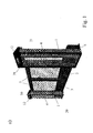
- FIG. 1a shows a perspective view of a sliding door construction which is intended to serve as an exemplary embodiment of the present invention.
- such a sliding door construction comprises fixed parts 1, which are arranged on both sides of the actual door opening.
- the door opening is closed by two sliding doors 2 and 3, wherein alternatively only one sliding door can be arranged.
- the two sliding doors 2 and 3 close synchronously and in opposite directions.
- Such sliding door structures are arranged in succession at the platform edge.
- the sliding door structures do not follow each other directly, but between sliding door constructions, as one of them is shown in Figure 1a), further wall elements are arranged, which do not constitute a door opening.
- Such wall elements are typically also formed similarly transparent. These wall elements are required inter alia, since otherwise the doors 2, 3 would encounter each other during the opening process.
- the fixed parts 1 comprise a bottom plate 6, on each of which the upper construction is attached.
- the upper construction essentially comprises in each case a frame 30, which is bounded in the head area by a cover 12.
- cover lamps 39 are arranged, which serve to emit optical signals during the opening process or respectively when closing the doors 2, 3, for example by lightning.
- As part of the superstructure of fixed parts 1 is made of aesthetic For example, a transparent area 4 arranged.
- each of these superstructures comprises a storage for the doors 2, 3, which will be described in detail below, as well as a drive.
- At least one fixed part per sliding door construction also includes a controller, which is connected, inter alia, to a total control of the entire system of sliding doors on a platform, so that a coordinated opening process or closing of all sliding doors at the right moment, that is at the correct position of the train, can be guaranteed ,
- the sliding doors 2, 3 are partially equipped with transparent areas 5.
- FIG. 1b such a sliding door construction is shown in a view from the side of the platform.
- the fixed parts 1 each comprise a frame 30.
- a transparent area 4 is arranged in each case.
- This transparent area is in a sense designed as a door, which can be opened to make the underlying functional parts such as drive and suspension and control for maintenance or installation accessible.
- these transparent areas 4 are provided with a lock 24.
- the sliding doors 2, 3 in turn likewise comprise a peripheral frame 26. Where the sliding doors adjoin one another, a sealing lip 28 is arranged on this frame. Preferably, such sealing lips 28 are configured such that the sealing lips 28 engage with one another by adjacent doors. Furthermore, transparent areas 5 are present in this frame 26. However, these transparent regions 5 do not extend all the way to the bottom, since in the lower region, due to the suspension arranged behind them, there is in each case one diaphragm region 25.
- the sliding doors can not be opened from the side of the platform in principle by simple manipulations.
- emergency opening options 23 are provided, which can only be operated using appropriate keys of the staff.
- the two sliding doors 2, 3 are designed to be cantilevered, that is, between the bottom and the lower edge of the door remains a small gap, which typically in the range of 5-30 mm.
- a fixed part 1 has, for example, a total width a of approximately 600 mm maximum, and the door opening may have a width b of 2100 mm. It is generally possible to open doors b in the range of up to 2500, normally up to 2200 mm. Depending on needs, the width of the door openings can be adjusted, and this is possible without the construction of the fixed parts 1 must be changed. So a construction is possible, which can be installed without major adjustments to the local conditions.
- the sliding doors 2, 3 have a height c, so that the upper edge of the sliding doors 2, 3 is located approximately 1500 mm above the floor. Normally, such doors are constructed with heights in the range of 1000-2000 mm.
- FIG. 1c shows a view of such a sliding door construction from the side of the tracks. It can be seen that behind the baffles 25 (see FIG. 1b) the actual suspension of the sliding doors is hidden. This suspension is covered with a cover 9, so that the pollution of the suspension can be avoided and thus the passengers can not access.
- handles 27 are provided on this side of the doors, with which the sliding doors 2, 3 can be opened.
- these handles 27 are designed to automatically open the doors when manipulated and still present, but also to allow door opening when force is applied, with no power left.
- Figure 1d shows such a sliding door construction in the open state from the side of the platform, as well as immediately below an associated floor plan. It can be seen that due to the much smaller width of the fixed structure 1, the sliding doors 2, 3 protrude laterally beyond these fixed parts 1. Specifically, each sliding door has a total width d including suspension of approximately 1700 mm (depending on the clear width of the door), since it has a guide rail 18 due to the cantilevered design, which rearwardly over the actual width of the door protrudes. Essential in this context is also that the overall construction depth is not too large, so that the required space is not too much platform surface consumed. The proposed construction is characterized by a very small construction depth, so in the above basic dimensions, the construction depth e is about 300 to 400 mm possible.
- Figure 2a shows a section through such a sliding door construction. It can be seen how two suspensions 10 and 11 are present, with both suspensions are arranged on the web side 21, and not on the platform side 20.
- the upper suspension 11 is disposed substantially in the region of the upper edge of the sliding doors 2, 3, and is described in detail below.
- the lower suspension 10 is arranged in the lowest area of the sliding doors 2, 3.
- the sliding doors 2, 3 have a cover 9, behind which the suspension 10 is hidden.
- the suspension 10 comprises a stationary part in the form of a guide element 19, which is arranged on the fixed part 1.
- a guide rail 18 is fastened to the respective sliding door and together with the guide element 19 forms a roller bearing or a ball bearing (for example a ball cage) via which the respective sliding door can be laterally displaced.
- the height f of the diaphragm area 25 or the cover 9 above the ground is approximately 400 mm, and the base plate 6 is spaced at a distance g of approximately 5 mm from the floor.
- the bottom plate 6 has a depth k of about 360 mm and is typically set back for safety reasons of the platform edge 46 by a distance 1 of about 75 mm. This value is project-specific and depends on the light profile of the train.
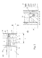
- FIGS. 2 b) -e The drive region is shown in detail in the following FIGS. 2 b) -e).
- Figure 2 b) is a sectional view. From this it can be seen that attached to the bottom plate 6 support columns 34, a horizontal guide member 19 am Fixed part is attached. This guide element 19 has a width, which in any case is less than the total width of the fixed part 1. Also attached to the bottom plate via a mounting plate 37 is the actual drive, which is ensured by a horizontally disposed electric motor 36.
- the electric motor 36 has, for example, a worm gear, which drives a toothed belt drive roller 31. Furthermore, 31 toothed belt deflection rollers 32 are arranged above this toothed belt drive roller, which should be discussed in connection with the figure 2d).
- a driver is provided with circulating toothed belt, or a fastening device 33 on the guide rail 18th
- FIGS. 2c) and d) show two views of the drive region from the tension side and the platform side, respectively. It can be seen that on the angled mounting plate 37, which is fixed by means of mounting screws 38 on the bottom plate 6, below the toothed belt drive roller 31 and above symmetrically laterally offset two Zahnriemenumlenkrollen 32 are arranged.
- the toothed belt 35 is fixed at its ends to the guide rail 18, and is deflected from each side from above via the Zahnriemenumlenkrolle 32 down to the toothed belt drive roller 31.
- the tension of the toothed belt 35 can thus be adjusted either by a lateral displacement of the toothed belt deflection rollers 32 or by a horizontal adjustment of the toothed belt drive roller 31 (also possible in each case via a sprung mounting with counter tension).
- This specific arrangement of the individual elements, ie horizontal drive motor with worm gear, toothed belt drive roller 31 with deflection over two toothed belt deflection rollers 32 allows a particularly compact design, and the use of a belt for driving proves to be particularly robust.
- the support columns are preferably designed as a hollow profile, wherein the guide member 19 is attached thereto from the platform side. It is possible to arrange two individual guide elements 19 on the two support columns 34, or else, and this is shown in FIG 2 e), it is also possible to form this guide element 19 as a rail, in which individual bearing elements are arranged distributed.
- the guide rail 18, which is fixed to the sliding doors 2, 3, is designed as a double U-profile, wherein the inner U-profile surrounds the guide member 19 for guiding and thus the inner U-profile serves as a tread, and wherein the outer U Profile is provided for the comprehensive protection of the leadership.
- the upper guide 11 is better seen in Figure 2f).
- an upper door profile 16 which forms part of the frame 26, is arranged.
- a guide rail 13 is attached.
- this guide rail has a width which corresponds approximately to the width of the sliding door 2, 3, but it can also protrude somewhat backwards over the door, as shown in Figure 1 d).
- a guide profile 15 is attached. However, it does not directly engage the guide rail 13 in the guide profile 15, but the upper guide is formed as a telescopic guide, in which a telescopic section 14 is movably arranged between these two elements.
- the telescopic profile 14 is thus both displaceable with respect to the guide rail 13 and with respect to the guide profile 15.
- the individual elements slide on each other, that is, the upper guide 11 is formed as a sliding guide.
- the use of the telescopic profile allows a particularly large width of the guide, without a chunky guide device is necessary.
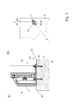
- FIG. 3a shows in detail the floor area of the construction.
- a bottom plate 6 is anchored with fastening elements 7 in the platform material 40. All elements of the fixed part 1 are then attached to this base plate 6.
- a bottom plate 6 is fixed on the platform by drilling appropriate holes in the platform. In these holes, the fasteners are either screwed (anchor bolts), or poured in, for example (anchor pins) or the like. About the above ground level upwardly protruding ends of the fasteners is now the Base plate 6 is placed, wherein the fastening elements 7 pass through corresponding provided in the bottom plate 6 holes 44, 45.
- Insulating spacer elements 42 are also provided between the bottom plate 7 and the bottom, wherein, for example, as shown in FIG. 3 a), they may be formed in the form of insulating washers 42. Similarly, 6 insulating washers 41 are now placed on top of the bottom plate and only then fixed the bottom plate with the aid of nuts 8 on the ground. The nuts 8 are screwed onto the upper end threaded fasteners 7.
- the floor panels are covered over their entire surface with an insulating coating.
- an insulating coating It is a coating of thermoplastic polyamide, such as thermoplastic PA11, which is configured with a thickness of about 0.4 mm.
- the material of the coating can be, for example, the product Rilsan® from Atofma (DE), such thermoplastic PA11 materials can be used, for example, in the fluidized bed process, in the electrostatic spray process, by powder spraying or the like. Applying, wherein the workpiece may be subjected to a surface pretreatment beforehand, for example, cleaning and application of a primer or the like.
- the holes 44, 45 designed much larger than the diameter of the fasteners 7.
- FIG. such a bottom plate is shown in FIG. It can be seen how in the area facing the platform, the fastening by three screws via three holes 45 rather in the central area, as in the lateral area, the two columns 30 of the fixed part 1 are arranged.
- the three tracks 44 facing the track area are widely distributed.
- the holes have a diameter q of 30 mm, while the anchor bolts or anchor pins 7 have a diameter r in the range of 12 mm.
- the first row of holes 44 is offset by w in the range of 110 mm to the rear, and the second row of holes 45 by 315 mm.
- the installation of such a sliding door design is particularly simple, since first the bottom plate as described above is fixed to the ground and then the fixed parts 1, that is their superstructure, put on respectively can be screwed.
- the fixed parts 1 are standard elements, which are designed independently of the width of the sliding doors. Between the fixed parts wall elements are now provided in the closed areas, which only need to be adjusted in length, which can be done either on site or before.
- the sliding doors 2, 3 can then be suspended from the track side, and last but not least the toothed belt 35 has to be placed around the corresponding elements 31 and 32, respectively, and tensioned.
- the controller can be designed so that it is self-learning, which means that when first switching on a measurement and an adjustment of the opening process takes place automatically.
- FIG. 5 shows a further exemplary embodiment of the invention.
- the upper guide is not arranged at the upper edge of the construction, but approximately at half height or slightly above the sliding doors. For aesthetic considerations, it may prove advantageous to make the top of the sliding doors as transparent as possible in order to minimize the constricting effect of such constructions occurring especially in narrow platforms.
- the upper guide is correspondingly arranged at half the height, and glass plates 48 and 49 are respectively arranged above and below.
- the arranged in the lower region lower guide is designed the same as in the above-discussed embodiment.
- the sliding doors 2, 3 are each designed with a central guide 54, but also the wall elements 47, while doing this intermediate rail 53 can hold either an upper and a lower glass plate as in the sliding doors , It is also possible to arrange this intermediate rail 53 behind a over the entire, above a lower aperture region 52 extending glass surface.
- the upper area and in particular the upper glass plate, which is exposed upwards and is not delimited by visually disturbing frame elements, enable a particularly slim construction, which is hardly distracting and restricting in the field of vision of the passengers.
- the upper guide 54 has a projection which protrudes to the rear beyond the trailing edge of the respective sliding doors. This increases the stability, especially shortly before closing the doors.
- FIG. 6 shows a section through the middle guide in detail. It can be seen that the fixed part 1 at half the height via a central support 55th has, on which the back, that is to say to the train area, a guide profile 56 is screwed.
- the guide profile 56 is formed as H-profile.
- the sliding door is formed from the upper and lower glass plates 48 and 49, respectively, and these two glass plates are held in the middle by the center support rail 54. Between the two glass plates 48 and 49 remains a horizontal slot, in which the support rail 54 has a corresponding horizontal slot, in which engages the guide profile 56 in the sense of a sliding.
- the upper guide is not designed as a telescopic guide, and it stabilizes the sliding doors only in the horizontal direction. Carrying in the vertical direction is completely taken over by the lower guide.
- this slot should for safety reasons, and to prevent contamination, have sealing lips 58, which close the slot to the people area with the door closed.
- the support rail 54 is arranged, for example, at a height H of about 1000 mm above the upper edge of the floor, and such a sliding door can have a very small thickness D of about 50 mm, and still have sufficient stability.
Abstract
Description
Die vorliegende Erfindung betrifft das Gebiet der Schiebetüren für Bahnsteige, das heisst das Gebiet der Türen, mit welchen der Personenbereich von Bahnsteigen vom Gleisbereich abgetrennt wird. Weiterhin betrifft sie ein Verfahren zur Montage einer solchen Schiebetür.The present invention relates to the field of sliding doors for platforms, that is to say the area of the doors with which the passenger area of platforms is separated from the track area. Furthermore, it relates to a method for mounting such a sliding door.
Es ist bereits bekannt, aus Sicherheitsgründen zwischen dem Personenbereich, das heisst dem eigentlichen Bahnsteig respektive Perron, und dem Gleisbereich Vorrichtungen anzubringen, welche, solange kein Zug eingefahren ist und im Stillstand ist, verhindern, dass Passagiere den Gleisbereich betreten können. Dies ist insbesondere bei Untergrundbahnstationen, wo typischerweise die Platzverhältnisse äusserst knapp sind, wesentlich.It is already known, for safety reasons between the person area, that is, the actual platform respectively platform, and the track area devices to install, which, as long as no train is retracted and is at a standstill, prevent passengers from entering the track area. This is especially important at subway stations, where typically the space is extremely scarce.
Es gibt in diesem Zusammenhang unterschiedliche Konstruktionen, wobei unterschieden wird zwischen so genannten Bahnsteigabschluss-Türen (platform screen doors) und Bahnsteig-Türen (platform gate doors).There are different constructions in this context, whereby a distinction is made between so-called platform screen doors and platform gate doors.
Bei den Bahnsteigabschluss-Türen wird bei gewissermassen geschlossenen, das heisst auch nach oben abgeschlossenen Bahnhofskonstruktionen ein vollständiger Abschluss zwischen dem Bahnsteig und dem Gleisbereich über die gesamte Höhe gewährleistet. Mit anderen Worten wird der dem Zug zur Verfügung stehende Raum vollständig durch eine Wand vom Raum der Passagiere abgetrennt, und es werden in der Trennwand normalerweise Schiebetüren vorgesehen, welche automatisch erst dann öffnen, wenn der Zug in der richtigen Position im Stillstand ist.In the case of the closed-platform doors, closed-off station constructions, which are also closed at the top, are completed guaranteed between the platform and the track area over the entire height. In other words, the space available to the train is completely separated by a wall from the space of the passengers, and sliding doors are normally provided in the partition which automatically open only when the train is in the right position at a standstill.
Bei den Bahnsteig-Türen wird nicht die gesamte Höhe zwischen diesen beiden Bereichen getrennt, sondern es wird nur eine halbe, ungefähr mannshohe Trennwand zur Verfügung gestellt, welche über stationäre Bereiche oder Fixteile verfügt, sowie über dazwischen angeordnete Schiebetüren. Diese Konstruktion kann einerseits dann angezeigt sein, wenn es sich nicht um einen geschlossenen Bahnhof handelt und somit keine obere Anschlusskante für eine Bahnsteigabschluss-Tür vorhanden wäre, sie kann aber andererseits auch aus anderen technischen Gründen zwingend sein. Dies zum Beispiel, wenn bestehende Bahnhofskonstruktionen nachgerüstet werden müssen, in welchen der Druckausgleich beim Einfahren des Zuges nur über eine entsprechende Belüftung durch den Passagierbereich möglich ist. Ausserdem kann es aus feuerpolizeilichen Gründen zwingend sein, dass ein ungehinderter Austausch von Luft zwischen dem Gleisbereich und dem Bahnsteigbereich möglich ist, was nur bei einer Bahnsteig-Tür in beinahe vollständiger Weise gewährleistet ist.In the platform doors, not the entire height between these two areas is separated, but it is provided only half a man-height partition, which has stationary areas or fixed parts, as well as disposed therebetween sliding doors. On the one hand, this construction may be indicated if it is not a closed railway station and thus there is no upper connecting edge for a railway terminating door, but on the other hand it may also be compulsory for other technical reasons. This, for example, if existing station structures must be retrofitted, in which the pressure compensation when entering the train is only possible via a corresponding ventilation through the passenger area. In addition, it may be imperative for fire police reasons that an unimpeded exchange of air between the track area and the platform area is possible, which is almost guaranteed only in the case of a platform door.
Die Konstruktion von Bahnsteig-Türen unterscheidet sich in technischer Hinsicht insofern von normalen Schiebetüren dahingehend, dass einerseits durch die anliegenden Drücke beim Einfahren des Zuges von der Seite des Zuges und andererseits von der anderen, der Bahnsteigseite, durch die möglichen Belastungen durch Personen (insbesondere in Stosszeiten) solche Türen enormen Belastungen ausgesetzt sind. Zudem können die Türen nicht mit einer oberhalb der Tür angeordneten Führung versehen werden, und es ist ausserdem wünschenswert, auch im Boden keine Führungsschienen oder Führungsnuten vorzusehen, dass solche in der Regel schnell verschmutzen und zu Betriebsunterbrüchen Anlass geben können. Es sind somit frei geführte Konstruktionen erforderlich, welche wesentlich höheren Belastungen ausgesetzt werden können, als dies bei konventionellen, aus anderen Bereichen bekannten Türen der Fall ist. Dazu kommt, dass in Bezug auf die Zuverlässigkeit Anforderungen gestellt werden müssen, welche weit über jenen anderer Anwendungen liegen. Einerseits müssen die Türen zuverlässige Öffnungszyklen im Bereich von Millionen problemlos überstehen, sie müssen leicht gewartet werden können, und insbesondere beim Retrofit muss eine Konstruktion zur Verfügung gestellt werden, welche einerseits sehr flexibel auf unterschiedliche Gegebenheiten (Bahnsteigkonstruktion, Abstände der Türen der Bahnen, Höhe, etc.) eingestellt werden kann, und welche zudem sehr schnell montiert werden kann, da sehr häufig die Montage von solchen Konstruktionen ohne Unterbruch der Transportdienstleistungen, das heisst beispielsweise nachts, vorgenommen werden muss.The construction of platform doors differs in technical respects from normal sliding doors in that on the one hand by the applied pressures when retracting the train from the side of the train and on the other hand, from the other, the platform side, by the possible loads by persons (in particular Stosszeiten) such doors are exposed to enormous loads. In addition, the doors can not be provided with a guide arranged above the door, and it is also desirable not to provide any guide rails or guide grooves in the floor, such that, as a rule, they can quickly become dirty and give rise to interruptions in operation. There are thus free-guided constructions required, which can be exposed to much higher loads, as is the case with conventional doors known from other fields. On top of that, in terms of reliability Requirements must be made, which far exceed those of other applications. On the one hand, the doors have to withstand reliable opening cycles in the range of millions, they must be easy to maintain, and especially in the retrofit, a construction must be provided, which on the one hand very flexible to different conditions (platform construction, distances of the doors of the tracks, height, etc.) can be adjusted, and which also can be mounted very quickly, since very often the assembly of such constructions without interruption of the transport services, that is, for example, at night, must be made.
Diesen enormen technischen Anforderungen steht entgegen, dass aus ästhetischen und platztechnischen Gründen möglichst schlanke Konstruktionen unter Verwendung von transparenten Bereichen gewünscht sind.These enormous technical requirements are contrary to the fact that for aesthetic and space reasons as slim as possible constructions are desired using transparent areas.
Der Erfindung liegt demnach die Aufgabe zugrunde, eine verbesserte Schiebetürkonstruktion für Bahnsteige vorzuschlagen, insbesondere als Bahnsteig-Tür. Konkret handelt es sich darum, eine Konstruktion vorzuschlagen, mit welcher ein Personenbereich von Bahnsteigen von einem Gleisbereich im geschlossenen Zustand abgetrennt werden kann, solange der Zustieg zu einem eingefahrenen Zug verhindert sein soll, und welche in geöffnetem Zustand bei eingefahrenem Zug den Zustieg ermöglicht, umfassend stationäre Bereiche sowie Schiebetüren, wobei sowohl die stationären Bereiche als auch die Schiebetüren eine Höhe im Bereich von 1-2 m oder sogar bis 2.5 oder 3 m über dem Boden des Personenbereiches aufweisen und oberhalb keine Mittel zur Abtrennung zwischen Personenbereich und Gleisbereich angeordnet sind,The invention is therefore an object of the invention to propose an improved sliding door construction for platforms, especially as a platform door. Specifically, it is a matter of proposing a construction with which a passenger area of platforms can be separated from a track area in the closed state, as long as the approach to a retracted train is to be prevented, and which in the open state with retracted train allows access, comprising stationary areas and sliding doors, wherein both the stationary areas and the sliding doors have a height in the range of 1-2 m or even to 2.5 or 3 m above the floor of the passenger area and above no means for separation between the passenger area and track area are arranged
Die Lösung dieser Aufgabe wird dadurch erreicht, dass die Schiebetüren frei tragend ausgebildet sind und in oder an den stationären Bereichen beweglich geführt sind, dass dazu eine obere und eine untere Führung vorhanden sind, wobei eine Führung als Rollenführung oder als Kugellinearführung ausgebildet ist, und eine Führung als Gleitführung oder als Rollenführung ausgebildet ist.The solution to this problem is achieved in that the sliding doors are designed to be free-carrying and are movably guided in or on the stationary areas that for this purpose an upper and a lower guide are provided, wherein a guide is designed as a roller guide or as a ball linear guide, and a Leadership as Sliding guide or is designed as a roller guide.
Der Kern der Erfindung besteht somit darin, eine doppelte Führung bei einer freitragenden Schiebetür vorzuschlagen, was eine erhöhte Stabilität gewährleistet und gleichzeitig eine hohe Zuverlässigkeit.The essence of the invention is thus to propose a double guide in a self-supporting sliding door, which ensures increased stability and at the same time high reliability.
Gemäss einer ersten bevorzugten Ausführungsform ist dabei die untere Führung als Rollenführung oder als Kugellinearführung ausgebildet, und die obere Führung als Gleitführung.According to a first preferred embodiment, the lower guide is designed as a roller guide or as a ball linear guide, and the upper guide as a sliding guide.
Bevorzugtermassen wird die untere Führung im wesentlichen im unteren Bereich der Schiebetür angeordnet, und/oder die obere Führung im wesentlichen an der Oberkante oder auf Halber Höhe der Schiebetür. So ist es möglich, dazwischen transparente Bereiche anzuordnen, so dass einerseits durch die Türen keine beengende Wirkung entsteht, und so dass die auf dem Bahnsteig befindlichen Passagiere den einfahrenden Zug beobachten können respektive dass die im Zug fahrenden Passagiere das Einfahren beobachten können.Preferably, the lower guide is arranged substantially in the lower region of the sliding door, and / or the upper guide substantially at the upper edge or at half the height of the sliding door. Thus, it is possible to arrange between transparent areas, so that on the one hand through the doors no restrictive effect, and so that the passengers on the platform can observe the incoming train respectively that the passengers on the train can observe the retraction.
Eine weitere bevorzugte Ausführungsform ist gekennzeichnet, dass der Antrieb der Schiebetüren an der als Rollenführung oder als Kugellinearführung ausgebildeten, bevorzugt unten angeordneten Führung angeordnet ist, und die Übertragung der Antriebskraft unter Zuhilfenahme eines Zahnriemens zwischen im stationären Bereich angeordnetem Antrieb und der Schiebetür erfolgt. Hinsichtlich kompakter Bauweise und Zuverlässigkeit erweist sich die Verwendung eines Zahnriemens im unteren Bereich als besonders vorteilhaft. Der Zahnriemen kann dabei zum Beispiel umlaufend gestaltet sein und über einen Mitnehmer mit der Schiebetür respektive insbesondere bevorzugt mit einer an der Schiebetür vorgesehenen Führungsschiene verbunden sein, oder es ist möglich, den Zahnriemen an seinen Enden mit einer an der Schiebetür vorgesehenen Führungsschiene fest zu verbinden.A further preferred embodiment is characterized in that the drive of the sliding doors is arranged on the guide designed as a roller guide or as a ball linear guide, preferably arranged below, and the transmission of the drive force takes place with the aid of a toothed belt between drive arranged in the stationary area and the sliding door. In terms of compact design and reliability, the use of a toothed belt in the lower area proves to be particularly advantageous. The toothed belt can be designed, for example, circumferentially and be connected via a driver with the sliding door respectively particularly preferably with a provided on the sliding guide rail, or it is possible to connect the timing belt at its ends with a guide rail provided on the sliding door.
Eine besonders bevorzugte Ausführungsform ist dadurch gekennzeichnet, dass für jede Schiebetür ein Antrieb auf einer Bodenplatte des jeweiligen stationären Bereiches befestigt ist, wobei es sich bevorzugt um einen elektromotorischen Antrieb z.B. mit Schneckengetriebe handelt, und dass der Antrieb eine Zahnriemenantriebsrolle antreibt, welche über Zahnriemenumlenkrollen von der Hauptrichtung des Zahnriemens nach unten oder nach oben versetzt angeordnet ist. Insbesondere dann, wenn der Zahnriemen an seinen Enden mit einer an der Schiebetür vorgesehenen Führungsschiene fest verbunden ist, kann so über die Zahnriemenantriebsrolle die Spannung des Zahnriemens kontrolliert und eingestellt werden und es ergibt sich eine besondere Zuverlässigkeit der Konstruktion.A particularly preferred embodiment is characterized in that for each sliding door a drive is mounted on a bottom plate of the respective stationary area, which is preferably an electromotive drive, for example with worm gear, and that the drive drives a toothed belt drive roller, which is arranged offset via toothed belt pulleys from the main direction of the belt down or up. In particular, when the toothed belt is firmly connected at its ends with a guide rail provided on the sliding door, the tension of the toothed belt can thus be controlled and adjusted by means of the toothed belt drive roller and a particular reliability of construction results.
Eine andere bevorzugte Ausführungsform zeichnet sich dadurch aus, dass am stationären Bereich ein horizontales Führungselement insbesondere über wenigstens zwei auf einer Bodenplatte befestigte Stützsäulen vorgesehen ist, welches Führungselement eine Länge von höchstens der Breite der stationären Bereiche aufweist, so dass dieses Führungselement nicht über die stationären Bereiche hinaus steht. Weiterhin ist dann an jeder Schiebetür eine Führungsschiene angeordnet, welche in das Führungselement eingreift oder dieses umgreift, wobei zur beweglichen Verschiebbarkeit in seitlicher Richtung Rollen oder Kugeln vorgesehen sind.Another preferred embodiment is characterized in that a horizontal guide element is provided at the stationary area, in particular via at least two support columns attached to a base plate, which guide element has a length of at most the width of the stationary areas, so that this guide element does not have the stationary areas stands out. Furthermore, a guide rail is then arranged on each sliding door, which engages in or engages around the guide element, wherein rollers or balls are provided for the movable displaceability in the lateral direction.
Um sicherzustellen, dass die Führungsschienen bei geöffneten Türen nicht kollidieren, respektive dass Türen möglichst nah nebeneinander angeordnet werden können, erweist es sich als vorteilhaft, die Führungselemente und die zugehörigen Führungsschienen von zwei nebeneinander liegenden Schiebetüren in ihrer Höhe wenigstens so weit zu versetzen, dass die Führungsschienen von geöffneten und an nebeneinander angeordneten Türöffnungen vorgesehenen Schiebetüren berührungsfrei übereinander zu liegen kommen. Bevorzugtermassen ist der Zahnriemen im wesentlichen unterhalb der Führungsschienen respektive des Führungselementes angeordnet. Die Ebene des Zahnriemens verläuft bevorzugtermassen horizontal.To ensure that the guide rails do not collide with the doors open, and that doors can be arranged as close together as possible, it proves to be advantageous to offset the guide elements and the associated guide rails of two adjacent sliding doors in height at least so far that the Guide rails of open and provided adjacent juxtaposed door openings sliding doors come to rest without contact over each other. Preferably, the toothed belt is arranged substantially below the guide rails or the guide element. The plane of the toothed belt preferably runs horizontally.
Gemäss einer anderen bevorzugten Ausführungsform sind beide Führungen, um auf der Bahnsteigseite eine möglichst elegante Konstruktion zur Verfügung zu stellen, welche zudem vor Zugriffen geschützt ist, auf der dem Bahnsteig abgewandten Seite der Schiebetür und der stationären Bereiche angeordnet.According to another preferred embodiment, both guides are to provide on the platform side as elegant as possible construction available, which is also protected against access, arranged on the side facing away from the platform of the sliding door and the stationary areas.
Um der weiten Verschiebbarkeit der Schiebetüren konstruktiv einfach gerecht zu werden, und seitlich überstehende Elemente nicht erforderlich zu machen, erweist es sich als vorteilhaft, die als Gleitführung ausgebildete obere Führung als eine wenigstens dreiteilige Teleskopführung auszubilden, welche über ein mit dem stationären Bereich fest verbundenes Führungsprofil, über ein mit der jeweiligen Schiebetür fest verbundene Führungsprofilschiene sowie über ein bezüglich beider anderer Elemente bewegliches Teleskop-Profil verfügt. Ein solches Teleskop-Profil kann auch auf Basis eines Rollenprofils an Stelle eines Gleitprofils ausgestaltet werden. Wird eine Gleitführung verwendet, erweist es sich zusätzlich gegebenenfalls als vorteilhaft, die gleitenden Bereiche mit einer speziellen Beschichtung, beispielsweise aus PTFE, zu versehen.In order to meet the wide displaceability of the sliding doors structurally simple, and not to make laterally projecting elements required, it proves to be advantageous, designed as a slide guide upper guide as an at least three-part telescopic guide form, which has a fixed to the stationary area guide profile, a firmly connected to the respective sliding door guide rail and a respect to both other elements movable telescopic profile. Such a telescopic profile can also be configured based on a roller profile instead of a sliding profile. If a sliding guide is used, it additionally proves to be advantageous if appropriate to provide the sliding areas with a special coating, for example made of PTFE.
Eine andere Ausführungsform der oberen Führung ist dadurch gekennzeichnet, dass die obere Führung im wesentlichen auf halber Höhe der Schiebetür angeordnet ist, wobei der oberhalb der oberen Führung angeordnete Bereich der Schiebetür aus Glas oder einem anderen im wesentlichen transparenten Material ausgebildet ist. Insbesondere wenn dann zudem diese vollständig oder teilweise transparente Platte mit einer im wesentlichen freiliegenden Oberkante ausgebildet ist ergibt sich eine elegante Konstruktion, welche auf die Passagiere eine wesentlich geringere beengende Wirkung ausübt als Konstruktionen, bei welchen an der Oberkante ein Rahmenbereich vorgesehen ist.Another embodiment of the upper guide is characterized in that the upper guide is arranged substantially at half the height of the sliding door, wherein the above the upper guide arranged portion of the sliding door made of glass or other substantially transparent material is formed. In particular, if then also this completely or partially transparent plate is formed with a substantially exposed top edge results in an elegant construction, which exerts on the passengers a much smaller restrictive effect than constructions in which a frame portion is provided at the top.
Die obere Führung kam bevorzugtermassen über ein rückseitig des Fixteiles angeordnetes und am Fixteil befestigtes Führungsprofil verfügen, insbesondere bevorzugt in Form eines H-Profiles, welches in einen Schlitz eines als Teil der Schiebetüren ausgestalteten Führungsprofils in Form einer Gleitschiene eingreift. Mit anderen Worten ist der Schlitz des Profils zum Bahnsteigbereich hin offen. Es erweist sich entsprechend zudem als vorteilhaft, diesen Schlitz mit Dichtlippen zu verschliessen, um ein Einklemmen oder eine Verschmutzung zu vermeiden.The upper guide was preferably on a rear side of the fixed part arranged and fixed to the fixed part guide profile, particularly preferably in the form of an H-profile, which engages in a slot designed as part of the sliding guide profile in the form of a slide rail. In other words, the slot of the profile is open to the platform area. It also proves to be advantageous according to close this slot with sealing lips to avoid trapping or contamination.
Problematisch an solchen Konstruktionen ist unter anderem die Tatsache, dass elektrische Potenzialdifferenzen zwischen dem Zug und dem Bahnsteigbereich vorhanden sind. Entsprechend ist eine umfassende Isolation des Bahnsteigsbereiches bezüglich der normalerweise zur Erdung verwendeten Schienen enorm wichtig. Entsprechend sollte die Schiebetürkonstruktion bezüglich des Bodens des Bahnsteiges möglichst gut isoliert sein. Dies kann erfindungsgemäss durch eine spezielle Ausgestaltung der Bodenplatte, auf welcher die stationären Bereiche angeordnet ist, respektive welche Bestandteil des stationären Bereiches bildet, erreicht werden.One of the problems with such constructions is the fact that electrical potential differences exist between the train and the platform area. Accordingly, comprehensive isolation of the platform area with respect to the rails normally used for grounding is enormously important. Accordingly, the sliding door structure should be as well insulated as possible with respect to the floor of the platform. This can according to the invention by a special embodiment of the bottom plate on which the stationary areas is arranged, respectively which forms part of the inpatient area.
Es muss darauf hingewiesen werden, dass diese spezielle Ausgestaltung respektive die Art der Montage einer solchen Bodenplatte unabhängig von der oben genannten Schiebetürkonstruktion erfinderischen Charakter aufweist und somit auch unabhängig davon schutzwürdig ist.It must be pointed out that this special embodiment or the type of mounting of such a floor plate, independently of the above-mentioned sliding door construction, has inventive character and thus is also worthy of protection independently of this.
Eine solche Konstruktion ist dadurch gekennzeichnet, dass die stationären Bereiche jeweils über wenigstens eine mit einer die gesamte Oberfläche überziehenden Isolationsschicht versehene Bodenplatte am Boden des Personenbereiches unter Zuhilfenahme von Anker-Schrauben oder -Stiften befestigt sind. Die Isolation der gesamten Oberfläche der Bodenplatte führt dazu, dass beispielsweise am Boden angeordneter Schmutz oder Feuchtigkeit nicht dazu führen kann, dass ein elektrischer Kontakt zwischen dem Boden und der Bodenplatte respektive der darauf angeordneten stationären Konstruktion stattfinden kann.Such a construction is characterized in that the stationary areas are fastened in each case via at least one provided with an insulating layer covering the entire surface base plate at the bottom of the people area with the aid of anchor bolts or pins. The insulation of the entire surface of the bottom plate results in that, for example, arranged on the ground dirt or moisture can not cause an electrical contact between the bottom and the bottom plate and the stationary structure arranged thereon can take place.
Besonders wirksam kann dies erreicht werden, wenn die die gesamte Bodenplatte überziehende Isolationsschicht aus einem Kunststoffmaterial, insbesondere bevorzugt aus einem thermoplastischen Polyamid, z.B. PA11, besteht, und mit einer Dicke im Bereich von 0.2 - 1.5 bevorzugt 0.25 - 1 mm ausgebildet ist.This can be achieved particularly effectively if the insulating layer covering the entire base plate is made of a plastic material, particularly preferably of a thermoplastic polyamide, e.g. PA11, consists, and is formed with a thickness in the range of 0.2 - 1.5 preferably 0.25 - 1 mm.
Eine erste bevorzugte Ausführungsform einer solchen Bodenplatte ist dadurch gekennzeichnet, dass die Bodenplatte über Befestigungslöcher verfügt, welche einen wesentlich grösseren Durchmesser aufweisen als die Anker-Schrauben respektive -Stifte (typischerweise Durchmesser der Bohrungen 2-5 mal grösser als Durchmesser der Schrauben respektive Stifte, mit welchen die Platte auf dem Boden befestigt wird), und dass zur Schubkraftübertragung und formschlüssigen Verbindung zwischen Bodenplatte und Anker-Schrauben respektive -Stiften ein isolierendes Füllmaterial, insbesondere aus Kunststoff oder Harz wie beispielsweise Acrylharz, angeordnet ist. Das Harz ist bevorzugt so gemischt, dass es zum einen die benötigte Festigkeit aufweist, zum anderen so spröde ist, dass es wieder entfernt werden kann, wenn die gesamte Struktur ersetzt werden muss.A first preferred embodiment of such a bottom plate is characterized in that the bottom plate has mounting holes, which have a substantially larger diameter than the anchor screws or pins (typically diameter of the holes 2-5 times larger than the diameter of the screws or pins, with which the plate is mounted on the ground), and that for thrust transfer and positive connection between the base plate and anchor bolts or pins, an insulating filler material, in particular made of plastic or resin such as acrylic resin, is arranged. The resin is preferably mixed in such a way that on the one hand it has the required strength and on the other hand it is so brittle that it can be removed again if the entire structure has to be replaced.
Erstens kann durch diese Konstruktion sichergestellt werden, dass Toleranzen zwischen dem Bohrmuster für die Schrauben respektive Stifte im Boden gut aufgefangen werden können, und zudem kann sichergestellt werden, dass die mit dem Boden in elektrischem Kontakt stehenden Schrauben respektive Stifte mit der Masse der Bodenplatte nicht in elektrischen Kontakt treten. Um anschliessend bei der Montage keine Kontaktierung zu erhalten, erweist es sich als vorteilhaft, zwischen Bodenplatte und Boden isolierende Elemente vorzusehen (auch als Distanzhalter) sowie zwischen den Befestigungsmitteln, mit welchen anschliessend die Bodenplatte mit den Schrauben respektive Stiften befestigt wird. Werden Stifte verwendet, so sind diese vorzugsweise an ihrem oberen Ende mit einem Gewinde versehen, und es werden Muttern auf dieses Gewinde zur Befestigung der Bodenplatte aufgeschraubt.First, this design ensures that tolerances between it is also possible to ensure that the screws or pins in electrical contact with the base do not come into electrical contact with the mass of the base plate. In order subsequently to obtain no contact during assembly, it proves to be advantageous to provide insulating elements between the base plate and the floor (also as spacers) and between the fastening means, with which subsequently the base plate is fastened with the screws or pins respectively. If pins are used, they are preferably threaded at their upper end, and nuts are threaded onto this thread to secure the bottom plate.
Des weiteren betrifft die vorliegende Erfindung ein Verfahren zur Montage (auch Retrofit) von solchen Schiebetürkonstruktionen an. Das Verfahren ist insbesondere dadurch gekennzeichnet, dass im Boden Bohrlöcher (beispielsweise im richtigen Muster unter Verwendung einer Schablone) vorgesehen werden, und dass dann in diesen Bohrlöchern Anker-Schrauben respektive -Stifte befestigt werden, wobei diese Schrauben respektive Stifte nach oben über den Boden genügend weit hervorragen. Die Schrauben respektive Stifte können eingeschraubt oder eingegossen werden. Anschliessend werden auf die Anker-Schrauben respektive -Stifte isolierende Distanzscheiben (im Sinne von Unterlagsscheiben, beispielsweise aus Kunststoff oder anderen isolierendem Material) aufgelegt. Dann wird eine Bodenplatte mit entsprechend vorgesehenen Bohrungen über die über den Boden hervorstehenden Anker-Schrauben respektive -Stifte gelegt.Furthermore, the present invention relates to a method for mounting (retrofit) of such sliding door designs. The method is particularly characterized in that holes are provided in the ground (for example in the correct pattern using a template), and then anchor bolts or pins are secured in these holes, these screws or pins enough up over the floor protrude far. The screws or pins can be screwed in or cast. Subsequently, insulating spacers (in the sense of washers, for example made of plastic or other insulating material) are placed on the anchor bolts or pins. Then a bottom plate is placed with holes provided accordingly over the protruding above the ground anchor screws or pins.
Die Grundplatte respektive Bodenplatte kann dabei auch im Bahnsteigboden versenkt werden.The base plate or base plate can also be sunk in the platform floor.
Die Bohrungen verfügen dabei, wie bereits weiter oben erwähnt, über einen Durchmesser, welcher wesentlich grösser ist als der Durchmesser der Schrauben respektive Stifte. Anfolgend werden die Zwischenräume zwischen den Bohrungen und den Anker-Schrauben respektive -Stiften mit isolierendem Füllmaterial ausgegossen, und dann wird die Bodenplatte nach Auflegen von weiteren isolierenden Distanzscheiben (zum Beispiel Unterlagsscheiben wie oben bereits erwähnt) unter Zuhilfenahme von Muttern o.ä. befestigt. Vorzugsweise ist der Aufbau der stationären Bereiche bereits auf der Bodenplatte aufgeschraubt o.ä. (dazu können bereits Gewindebohrungen, in Form von Sacklöchern, in der oberen Fläche Bodenplatte vorgesehen sein), wobei sichergestellt wird, dass keine Kontaktierung mit dem Boden stattfmden kann. Nachdem also die Ankerbolzen in die Plattform montiert sind, wird die gesamte Struktur (Fixteil), welches bereits in der Fabrik vormontiert und ausgetestet wird (Fixteil inklusive Schiebeflügel werden in der Fabrik komplett montiert und in Betrieb genommen), aufgeschraubt.The holes have, as already mentioned above, a diameter which is substantially larger than the diameter of the screws or pins. Subsequently, the spaces between the holes and the anchor screws or pins with insulating filling material are poured out, and then the bottom plate is replaced after applying more insulating spacers (for example, washers as mentioned above) under With the help of nuts or similar attached. Preferably, the structure of the stationary areas is already screwed on the bottom plate o.ä. (To this end, threaded holes, in the form of blind holes, in the upper surface of the bottom plate may be provided), whereby it is ensured that no contact with the ground can take place. Thus, after the anchor bolts are mounted in the platform, the entire structure (fixed part), which is already pre-assembled and tested in the factory (fixed part including sliding sash are completely assembled and put into operation in the factory), screwed.
Weitere bevorzugte Ausführungsformen der erfmdungsgemässen Schiebetürkonstruktion und des erfindungsgemässen Verfahrens zur Montage einer solchen Schiebetürkonstruktion sind in den abhängigen Ansprüchen beschrieben.Further preferred embodiments of the sliding door construction according to the invention and of the method according to the invention for mounting such a sliding door construction are described in the dependent claims.
Die Erfindung soll nachfolgend anhand von Ausführungsbeispielen im Zusammenhang mit den Zeichnungen näher erläutert werden. Es zeigen:
- Fig. 1a)
- eine perspektivische Ansicht einer Schiebetürkonstruktion nach der Erfindung, b) eine Ansicht auf eine geschlossene Schiebetürkonstruktion von der Seite des Bahnsteigs, c) eine Ansicht auf eine geschlossene Schiebetürkonstruktion von der Seite der Geleise, d) Ansicht auf eine geöffnete Schiebetürkonstruktion von der Seite des Bahnsteigs zusammen mit einem darunter angeordneten entsprechenden Grundriss;
- Fig. 2
- a) einen Schnitt durch eine Schiebetürkonstruktion über die gesamte Höhe, b) ein Detail des Fussbereiches aus einem Schnitt gemäss a), c) eine Sicht auf den Antriebsbereich des Fixteiles von der Seite der Geleise bei geschlossener Schiebetür, d) eine Sicht auf den Eintrittsbereich des Fixteiles von der Seite des Bahnsteigs bei geschlossener Tür, e) eine perspektivische Ansicht des Antriebsbereiches (möglicherweise vorhandenes Gehäuse entfernt), f) ein Detail des Kopfbereiches aus einem Schnitt gemäss a);
- Fig. 3a)
- ein Detail des Fussbereiches mit Bodenplatte, b) Detailansicht einer Bohrung mit Füllung, c) eine Bodenplatte in Aufsicht;
- Fig. 4
- perspektivische Ansichten eines anderen Ausführungsbeispiels, wobei a) den geschlossenen Zustand und b) den geöffneten Zustand darstellen; und
- Fig. 5
- einen detaillierten Schnitt durch eine mögliche, auf halber Höhe der Schiebetür angeordnete obere Führung.
- Fig. 1a)
- a perspective view of a sliding door construction according to the invention, b) a view of a closed sliding door construction from the side of the platform, c) a view of a closed sliding door construction from the side of the tracks, d) view of an opened sliding door construction from the side of the platform with a corresponding floor plan arranged thereunder;
- Fig. 2
- a) a section through a sliding door construction over the entire height, b) a detail of the foot area from a section according to a), c) a view of the drive area of the fixed part from the side of the tracks with the sliding door closed, d) a view of the entry area the fixed part from the side of the platform with the door closed, e) a perspective view of the drive area (possibly existing housing removed), f) a detail of the head area from a section according to a);
- Fig. 3a)
- a detail of the foot area with base plate, b) detailed view of a hole with filling, c) a bottom plate in supervision;
- Fig. 4
- perspective views of another embodiment, wherein a) represent the closed state and b) the open state; and
- Fig. 5
- a detailed section through a possible, located halfway up the sliding door upper guide.
Figur 1a) zeigt in perspektivischer Ansicht eine Schiebetürkonstruktion, welche zur Illustration der vorliegenden Erfindung als Ausführungsbeispiel dienen soll. Die Ausführungsbeispiele, welche in der Folge beschrieben werden, sollen aber nur zur Illustration hinzugezogen werden, nicht zur Einschränkung des Schutzbereiches, wie er in den Patentansprüchen definiert ist.FIG. 1a) shows a perspective view of a sliding door construction which is intended to serve as an exemplary embodiment of the present invention. The embodiments which are described in the following, but should be consulted only for illustration, not to limit the scope, as defined in the claims.
Grundsätzlich umfasst eine solche Schiebetürkonstruktion Fixteile 1, welche beiderseits der eigentlichen Türöffnung angeordnet sind. Die Türöffnung wird durch zwei Schiebetüren 2 und 3 verschlossen, wobei alternativ auch nur eine Schiebetüre angeordnet sein kann. Die beiden Schiebetüren 2 und 3 schliessen synchron und gegenläufig. Solche Schiebetürkonstruktionen sind in Folge an der Bahnsteigkante angeordnet. Die Schiebetürkonstruktionen folgen aber nicht unmittelbar aufeinander, sondern zwischen Schiebetürkonstruktionen, wie eine davon in Figur 1a) dargestellt ist, sind weitere Wandelemente angeordnet, welche keine Türöffnung darstellen. Solche Wandelemente sind typischerweise ebenfalls ähnlich transparent ausgebildet. Diese Wandelemente sind unter anderem erforderlich, da ansonsten die Türen 2, 3 beim Öffnungsvorgang aneinander stossen würden.In principle, such a sliding door construction comprises fixed
Die Fixteile 1 umfassen eine Bodenplatte 6, auf welcher jeweils die Oberkonstruktion befestigt ist. Die Oberkonstruktion umfasst im wesentlichen jeweils einen Rahmen 30, welcher im Kopfbereich durch eine Abdeckung 12 begrenzt ist. In der Abdeckung sind Lampen 39 angeordnet, welche dazu dienen, beim Öffnungsvorgang respektive beim Schliessen der Türen 2, 3 für die Passanten optische Signale abzugeben, beispielsweise durch Blitze. Im Rahmen der Oberkonstruktion der Fixteile 1 ist aus ästhetischen Gründen beispielsweise ein transparenter Bereich 4 angeordnet. Weiterhin umfasst jede dieser Oberkonstruktionen eine Lagerung für die Türen 2, 3, welche weiter unten im Detail beschrieben werden wird, sowie einen Antrieb. Wenigstens ein Fixteil pro Schiebetürkonstruktion umfasst zudem eine Steuerung, welche u. a. an eine Gesamtsteuerung des gesamten Systems von Schiebetüren an einem Bahnsteig angeschlossen ist, damit ein koordinierter Öffnungsvorgang respektive Schliessvorgang sämtlicher Schiebetüren im richtigen Moment, das heisst bei der korrekten Position des Zuges, gewährleistet werden kann. Auch die Schiebetüren 2, 3 sind teilweise mit transparenten Bereichen 5 ausgestattet.The fixed
In Figur 1b) ist eine solche Schiebetürkonstruktion in einer Ansicht von der Seite des Bahnsteigs dargestellt. Hierbei wird erkennbar, dass die Fixteile 1 jeweils einen Rahmen 30 umfassen. Innerhalb dieses Rahmens ist jeweils ein transparenter Bereich 4 angeordnet. Dieser transparente Bereich ist gewissermassen als Tür ausgebildet, welche geöffnet werden kann, um die dahinter liegenden funktionellen Teile wie beispielsweise Antrieb und Aufhängung sowie Steuerung für Wartung respektive Installation zugänglich zu machen. Zu diesem Zweck sind diese transparenten Bereiche 4 mit einem Schloss 24 versehen.In Figure 1b) such a sliding door construction is shown in a view from the side of the platform. It can be seen here that the fixed
Die Schiebetüren 2, 3 ihrerseits umfassen ebenfalls einen umlaufenden Rahmen 26. Dort, wo die Schiebetüren aneinander grenzen, ist an diesem Rahmen eine Dichtlippe 28 angeordnet. Vorzugsweise sind solche Dichtlippen 28 derart ausgestaltet, dass die Dichtlippen 28 von aneinander grenzenden Türen ineinander greifen. Weiterhin sind transparente Bereiche 5 in diesem Rahmen 26 vorhanden. Diese transparenten Bereiche 5 erstrecken sich aber nicht ganz bis zum Boden, da im unteren Bereich, infolge der dahinter angeordneten Aufhängung, jeweils ein Blendenbereich 25 vorhanden ist.The sliding
Die Schiebetüren können von der Seite des Bahnsteigs im Prinzip nicht durch einfache Manipulationen geöffnet werden. Um notfalls aber eine mechanische Öffnung der Schiebetüren 2, 3 zu ermöglichen, sind Notöffnungsmöglichkeiten 23 vorgesehen, welche aber nur unter Verwendung entsprechender Schlüssel des Personals betätigt werden können. Die beiden Schiebetüren 2, 3 sind frei tragend ausgebildet, das heisst zwischen dem Boden und der Unterkante der Tür verbleibt ein kleiner Spalt, welcher typischerweise im Bereich von 5-30 mm beträgt.The sliding doors can not be opened from the side of the platform in principle by simple manipulations. In order to allow, if necessary, but a mechanical opening of the sliding
Ein Fixteil 1 verfügt beispielsweise über eine gesamte Breite a von circa maximal 600 mm, und die Türöffnung kann eine Breite b von 2100mm aufweisen. Möglich sind grundsätzlich Türöffnungsbereiten b im Bereich von bis zu 2500, normalerweise von bis zu 2200 mm. Je nach Bedürfnissen kann die Breite der Türöffnungen angepasst werden, und dies ist möglich, ohne dass dabei die Konstruktion der Fixteile 1 geändert werden muss. So ist eine Konstruktion möglich, welche ohne grosse Anpassungen an die lokalen Verhältnisse installiert werden kann. Die Schiebetüren 2, 3 verfügen über eine Höhe c, so dass die Oberkante der Schiebetüren 2, 3 circa 1500 mm über dem Boden angeordnet ist. Normalerweise werden solche Türen mit Höhen im Bereich von 1000-2000 mm konstruiert.A
Figur 1c) zeigt eine Ansicht einer solchen Schiebetürkonstruktion von der Seite der Geleise. Hierbei wird erkennbar, dass hinter den Blenden 25 (vergleiche Figur 1b) die eigentliche Aufhängung der Schiebetüren verborgen ist. Diese Aufhängung ist mit einer Abdeckung 9 abgedeckt, damit die Verschmutzung der Aufhängung vermieden werden kann und damit die Passagiere nicht zugreifen können.Figure 1c) shows a view of such a sliding door construction from the side of the tracks. It can be seen that behind the baffles 25 (see FIG. 1b) the actual suspension of the sliding doors is hidden. This suspension is covered with a
Da es unter Umständen in Notsituationen erforderlich sein kann, dass im Zug befindliche Passagiere solche Schiebetüren 2, 3 manuell Öffnen, sind auf dieser Seite der Türen Handgriffe 27 vorgesehen, mit welchen die Schiebetüren 2, 3 geöffnet werden können. Typischerweise sind diese Handgriffe 27 derart ausgestaltet, dass sie bei Manipulation und noch vorhandenem Strom ein Öffnen der Türen in automatisierter Art und Weise auslösen, und dass Sie aber bei nicht mehr vorhandenem Strom die Öffnung der Tür unter Kraftanwendung ebenfalls ermöglichen.Since it may be necessary under certain circumstances in emergency situations that passengers in the train open such sliding
Figur 1d) zeigt eine solche Schiebetürkonstruktion in geöffnetem Zustand von der Seite des Bahnsteiges, sowie gleich darunter einen zugehörigen Grundriss. Dabei wird erkennbar, dass aufgrund der wesentlich geringeren Breite der Fixkonstruktion 1 die Schiebetüren 2, 3 seitlich über diese Fixteile 1 hinausragen. Konkret verfügt jede Schiebetüre über eine gesamte Breite d inklusive Aufhängung von circa 1700 mm (abhängig von der lichten Weite der Türe), da sie aufgrund der freitragenden Ausgestaltung über eine Führungsschiene 18 verfügt, welche nach hinten über die eigentliche Breite der Tür hinausragt. Wesentlich in diesem Zusammenhang ist zudem, dass die Konstruktionstiefe insgesamt nicht zu gross wird, damit der benötigte Platz nicht zu viel Bahnsteigfläche verbraucht. Die vorgeschlagene Konstruktion zeichnet sich über eine sehr geringe Konstruktionstiefe aus, so ist bei den oben angegebenen grundsätzlichen Dimensionen die Konstruktionstiefe e circa 300 bis 400 mm möglich.Figure 1d) shows such a sliding door construction in the open state from the side of the platform, as well as immediately below an associated floor plan. It can be seen that due to the much smaller width of the fixed
Figur 2a) zeigt einen Schnitt durch eine derartige Schiebetürkonstruktion. Dabei wird erkennbar, wie zwei Aufhängungen 10 und 11 vorhanden sind, wobei beide Aufhängungen auf der Bahnseite 21 angeordnet sind, und nicht auf der Bahnsteigseite 20. Die obere Aufhängung 11 ist im wesentlichen im Bereich der Oberkante der Schiebetüren 2, 3 angeordnet, und wird im Detail weiter unten beschrieben.Figure 2a) shows a section through such a sliding door construction. It can be seen how two
Die untere Aufhängung 10 ist im untersten Bereich der Schiebetüren 2, 3 angeordnet. Die Schiebetüren 2, 3 verfügen über eine Abdeckung 9, hinter welcher die Aufhängung 10 verborgen ist. Die Aufhängung 10 umfasst einen stationären Teil in Form eines Führungselementes 19, welches am Fixteil 1 angeordnet ist. An der jeweiligen Schiebetür ist eine Führungsschiene 18 befestigt, welche zusammen mit dem Führungselement 19 ein Rollenlager oder ein Kugellager (z.B. Kugelkäfig) bildet, über welches die jeweilige Schiebetür seitlich verschoben werden kann.The
Die Höhe f des Blendenbereiches 25 respektive der Abdeckung 9 über dem Boden beträgt circa 400 mm, und die Bodenplatte 6 ist mit einem Abstand g von circa 5 mm vom Boden beabstandet. Die Bodenplatte 6 verfügt über eine Tiefe k von circa 360 mm und ist typischerweise aus Sicherheitsgründen von der Bahnsteigkante 46 um einen Abstand 1 von circa 75 mm zurückversetzt. Dieser Wert ist projektspezifisch und abhängig vom Lichtprofil des Zuges. Die Bodenplatte ist mit zwei Reihen von Verankerungselementen 7 im Boden verankert, wobei die erste Reihe der Verankerungselemente um h im Bereich von 110 mm von der hinteren Kante der Bodenplatte 6 versetzt ist, und die beiden Reihen der Schrauben um circa i = 210 mm beabstandet sind.The height f of the
Der Antriebsbereich ist in den anfolgenden Figuren 2 b)-e) im Detail dargestellt. In Figur 2 b) ist eine Schnittdarstellung angegeben. Aus dieser wird ersichtlich, dass an auf der Bodenplatte 6 befestigten Stützsäulen 34 ein horizontales Führungselement 19 am Fixteil befestigt ist. Dieses Führungselement 19 verfügt über eine Breite, welche auf jeden Fall geringer ist als die Gesamtbreite des Fixteiles 1. Ebenfalls auf der Bodenplatte über eine Montageplatte 37 befestigt ist der eigentliche Antrieb, welcher über einen horizontal angeordneten Elektromotor 36 gewährleistet ist. Der Elektromotor 36 verfügt z.B. über ein Schneckengetriebe, welches eine Zahnriemenantriebsrolle 31 antreibt. Weiterhin sind oberhalb dieser Zahnriemenantriebsrolle 31 Zahnriemenumlenkrollen 32 angeordnet, welche im Zusammenhang mit der Figur 2d) besprochen werden sollen. Zur Befestigung des Zahnriemens 35 ist entweder ein Mitnehmer bei umlaufendem Zahnriemen vorgesehen, oder aber eine Befestigungsvorrichtung 33 an der Führungsschiene 18.The drive region is shown in detail in the following FIGS. 2 b) -e). In Figure 2 b) is a sectional view. From this it can be seen that attached to the
Die Figuren 2c) und d) zeigen zwei Ansichten auf den Antriebsbereich von der Zugseite respektive der Bahnsteigseite. Es kann erkannt werden, dass auf der gewinkelten Montageplatte 37, welche mittels Montageschrauben 38 auf der Bodenplatte 6 befestigt ist, unten die Zahnriemenantriebsrolle 31 und oberhalb davon symmetrisch seitlich versetzt zwei Zahnriemenumlenkrollen 32 angeordnet sind.FIGS. 2c) and d) show two views of the drive region from the tension side and the platform side, respectively. It can be seen that on the angled mounting
In diesem Ausführungsbeispiel ist der Zahnriemen 35 mit seinen Enden an der Führungsschiene 18 befestigt, und wird jeweils von jeder Seite von oben über die Zahnriemenumlenkrolle 32 nach unten zur Zahnriemenantriebsrolle 31 umgelenkt. Die Spannung des Zahnriemens 35 kann so entweder durch ein seitliches Verschieben der Zahnriemenumlenkrollen 32 oder über eine horizontale Verstellung der Zahnriemenantriebsrolle 31 eingestellt werden (auch jeweils über eine gefederte Lagerung mit Gegenspannung möglich). Diese spezifische Anordnung der einzelnen Elemente, das heisst horizontaler Antriebsmotor mit Schneckengetriebe, Zahnriemenantriebsrolle 31 mit Umlenkung über zwei Zahnriemenumlenkrollen 32, erlaubt eine besonders kompakte Bauweise, und die Verwendung eines Zahnriemens zum Antrieb erweist sich als besonders robust.In this embodiment, the
Aus der perspektivischen Ansicht gemäss Figur 2e) geht hervor, dass die Stützsäulen bevorzugtermassen als Hohlprofil ausgebildet sind, wobei das Führungselement 19 von der Bahnsteigseite daran befestigt ist. Es ist dabei möglich, an den beiden Stützsäulen 34 zwei individuelle Führungselemente 19 anzuordnen, oder aber, und dies ist in Figur 2 e) dargestellt, es ist möglich dieses Führungselement 19 ebenfalls als Schiene auszubilden, bei welchem einzelne Lagerelemente verteilt angeordnet sind. Die Führungsschiene 18, welche an den Schiebetüren 2, 3 befestigt ist, ist als doppeltes U-Profil ausgestaltet, wobei das innere U-Profil das Führungselement 19 zur Führung umgreift und somit das innere U-Profil als Lauffläche dient, und wobei das äussere U-Profil zum umgreifenden Schutz der Führung vorgesehen ist.From the perspective view according to Figure 2e) shows that the support columns are preferably designed as a hollow profile, wherein the
Die obere Führung 11 wird aus Figur 2f) besser ersichtlich. An der Oberkante der Schiebetüren 2, 3 ist ein oberes Türprofil 16, welches Teil des Rahmens 26 bildet, angeordnet. An diesem oberen Türprofil 16 ist eine Führungsprofilschiene 13 befestigt. Vorzugsweise verfügt diese Führungsprofilschiene über eine Breite, welche ungefähr der Breite der Schiebetür 2, 3 entspricht, sie kann aber auch etwas nach hinten über die Tür hervorstehen, wie dies in Figur 1 d) dargestellt ist. Als Fixelement ist im Gegenzug im oberen Bereich des Fixteiles 1 ein Führungsprofil 15 befestigt. Es greift nun aber nicht direkt die Führungsprofilschiene 13 in das Führungsprofil 15, sondern die obere Führung ist als Teleskop-Führung ausgebildet, bei welchem ein Teleskopprofil 14 beweglich zwischen diesen beiden Elementen angeordnet ist. Das Teleskopprofil 14 ist somit sowohl verschieblich bezüglich der Führungsprofilschiene 13 als auch bezüglich des Führungsprofils 15. Die einzelnen Elemente gleiten aufeinander, das heisst die obere Führung 11 ist als Gleitführung ausgebildet. Die Verwendung des Teleskopprofils erlaubt eine besonders grosse Weite der Führung, ohne dass eine klobige Führungsvorrichtung notwendig ist.The
Zusätzliches wesentliches Element der vorliegenden Schiebetürkonstruktion ist die Befestigung am Boden. Figur 3a) zeigt in einem Detail den Bodenbereich der Konstruktion. Eine Bodenplatte 6 ist mit Befestigungselementen 7 im Bahnsteigmaterial 40 verankert. Sämtliche Elemente des Fixteiles 1 sind anschliessend auf dieser Bodenplatte 6 befestigt. Zunächst wird also eine Bodenplatte 6 auf dem Bahnsteig befestigt, indem entsprechende Löcher in den Bahnsteig gebohrt werden. In dieser Löcher werden die Befestigungselemente entweder eingeschraubt (Anker-Schrauben), oder beispielsweise eingegossen (Anker-Stifte) oder ähnliches. Über die über das Bodenniveau nach oben hervorstehenden Enden der Befestigungselemente wird nun die Bodenplatte 6 gelegt, wobei die Befestigungselemente 7 durch entsprechend in der Bodenplatte 6 vorgesehene Bohrungen 44, 45 hindurchtreten. Zwischen Bodenplatte 7 und Boden werden zudem isolierende Distanzelemente 42 vorgesehen, wobei diese beispielsweise, wie in Figur 3a) dargestellt, in Form von isolierenden Unterlagsscheiben 42 ausgebildet sein können. Gleichermassen werden nun von oben auf die Bodenplatte 6 isolierende Unterlagsscheiben 41 aufgelegt und erst dann die Bodenplatte unter Zuhilfenahme von Muttern 8 am Boden fixiert. Die Muttern 8 werden auf am oberen Ende mit einem Gewinde versehenen Befestigungselemente 7 aufgeschraubt.An additional essential element of the present sliding door construction is the attachment to the floor. Figure 3a) shows in detail the floor area of the construction. A
Die Bodenplatten sind über ihre ganze Oberfläche mit einer isolierenden Beschichtung überzogen. Es handelt sich dabei um eine Beschichtung aus thermoplastischem Polyamid, beispielsweise thermoplastischem PA11, welche mit einer Dicke von ca. 0.4 mm ausgestaltet ist. Es kann sich bei Material der Beschichtung beispielsweise um das Produkt Rilsan® von Atofma (DE) handeln, solche thermoplastischen PA11-Materialien können beispielsweise im Wirbelsinterverfahren, im elektrostatischen Sprühverfahren, durch Pulversprühen o.ä. Aufgebracht werden, wobei das Werkstück zuvor einer Oberflächenvorbehandlung unterzogen werden kann, beispielsweise Reinigung und Aufbringung eines Primer oder ähnliches. Um die elektrische Isolationswirkung zwischen Bahnsteig und Schiebetürkonstruktion sicherzustellen, werden zudem die Bohrungen 44, 45 wesentlich grösser ausgestaltet, als der Durchmesser der Befestigungselemente 7. Nach der Befestigung der Befestigungselemente 7 im Boden, dem Auflegen der Distanzelemente 42 und der Bodenplatte 6 wird der Zwischenraum zwischen den Befestigungselementen 7 und dem Rand der Bohrungen 44, 45 mit einem elektrisch isolierenden Füllmaterial 43, beispielsweise Acrylharz, z.B. Acryl-Giessharz Beracryl® der Firma Troller AG, ausgegossen. Das Material wird bevorzugtermassen dabei derart gemischt, dass es einerseits eine genügende Festigkeit zur Halterung aufweist, und andererseits eine Sprödigkeit, welche eine Entfernung bei Demontage wieder ermöglicht. Durch die isolierende Wirkung dieses Füllmateriales wird sichergestellt, dass im Bereich der Befestigungselemente sicher keine elektrische Kontaktierung mit dem Boden stattfindet. Wie in Figur 3b) ersichtlich wird dabei so ausgelegt, dass ein genügender Toleranzkreis p von 10 bis 20 mm entsteht.The floor panels are covered over their entire surface with an insulating coating. It is a coating of thermoplastic polyamide, such as thermoplastic PA11, which is configured with a thickness of about 0.4 mm. The material of the coating can be, for example, the product Rilsan® from Atofma (DE), such thermoplastic PA11 materials can be used, for example, in the fluidized bed process, in the electrostatic spray process, by powder spraying or the like. Applying, wherein the workpiece may be subjected to a surface pretreatment beforehand, for example, cleaning and application of a primer or the like. In order to ensure the electrical insulation effect between the platform and sliding door construction, also the
Im Detail ist eine solche Bodenplatte in Figur 4 dargestellt. Es kann erkannt werden, wie im dem Bahnsteig zugewandten Bereich die Befestigung durch drei Schrauben über drei Bohrungen 45 eher im zentralen Bereich erfolgt, da im seitlichen Bereich die beiden Säulen 30 des Fixteiles 1 angeordnet sind. Die drei dem Gleisbereich zugewandten Bohrungen 44 sind breit verteilt. Die Bohrungen verfügen über einen Durchmesser q von 30 mm, während die Anker-Schrauben respektive Anker-Stifte 7 über einen Durchmesser r im Bereich von 12 mm verfügen. Die erste Reihe von Bohrungen 44 ist um w im Bereich von 110 mm nach hinten versetzt, und die zweite Reihe von Bohrungen 45 um 315 mm. Die Bodenplatte 6 verfügt über eine gesamte Breite u von circa 600 mm, wobei die äusseren beiden Bohrungen 44 der ersten Reihe von der Mitte um t = 265 mm versetzt sind, während die seitlichen Bohrungen 45 der zweiten Reihe um s = 100 mm versetzt sind.In detail, such a bottom plate is shown in FIG. It can be seen how in the area facing the platform, the fastening by three screws via three
Die Montage einer solchen Schiebetürkonstruktion gestaltet sich besonders einfach, da zunächst die Bodenplatte wie oben beschrieben am Boden befestigt wird und anschliessend die Fixteile 1, das heisst deren Oberkonstruktion, aufgesetzt respektive aufgeschraubt werden kann. Bei den Fixteilen 1 handelt es sich um Standardelemente, welche unabhängig von der Breite der Schiebetüren ausgestaltet sind. Zwischen den Fixteilen werden nun in den geschlossenen Bereichen Wandelemente vorgesehen, welche nur noch in ihrer Länge angepasst werden müssen, was entweder bauseitig oder bereits davor geschehen kann. Die Schiebetüren 2, 3 können anschliessend von der Gleisseite eingehängt werden, und zu guter letzt muss nur noch der Zahnriemen 35 um die entsprechenden Elemente 31 respektive 32 herum gelegt und gespannt werden. Die Steuerung kann so ausgelegt werden, dass die selbstlernend ist, was heisst das beim ersten Einschalten automatisch ein Ausmessen und eine Einstellung des Öffnungsvorganges stattfindet.The installation of such a sliding door design is particularly simple, since first the bottom plate as described above is fixed to the ground and then the fixed
Ein wichtiger Punkt zu Installation ist die Tatsache, dass die gesamte Fixstruktur inklusive Türflügel bereits im Werk montiert und getestet werden kann. Auf der Plattform müssen tatsächlich nur die Bolzen in die Plattform installiert werden und danach die gesamte Fixstruktur darauf aufgesetzt werden. Die Kabel werden vorgängig verlegt und sobald eine Fixstruktur montiert ist sofort angeschlossen. Ab diesem Augenblick können die Türen automatisch öffnen und schliessen (dies ist insbesondere beim nächtlichen Retrofit verfahren nötig, da ja am nächsten morgen die Züge wieder fahren). Das bedeutet auch, dass während der Installationsphase tagsüber die bereits installierten Türen bereits automatisch funktionieren.An important point about installation is the fact that the entire fix structure including the door can already be assembled and tested at the factory. On the platform, in fact, only the bolts need to be installed in the platform and then the entire fixed structure placed on top. The cables are laid in advance and immediately connected as soon as a fixed structure is installed. From this At the moment, the doors can open and close automatically (this is especially necessary for the nightly retrofit procedure, as the trains leave the next morning). This also means that during the installation phase during the day already installed doors already work automatically.
In Figur 5 ist ein weiteres Ausführungsbeispielen der Erfindung dargestellt. Hierbei ist die obere Führung nicht an der Oberkante der Konstruktion angeordnet, sondern ungefähr auf halber Höhe oder etwas oberhalb der Schiebetüren. Aus ästhetischen Überlegungen kann es sich als vorteilhaft erweisen, den oberen Bereich der Schiebetüren möglichst transparent zu gestalten, um die insbesondere bei schmalen Bahnsteigen auftretende beengende Wirkung von solchen Konstruktionen möglichst gering zu halten. In der Konstruktion gemäss Figur 5 ist entsprechend die obere Führung auf halber Höhe angeordnet, und oberhalb sowie unterhalb sind jeweils Glasplatten 48 respektive 49 angeordnet. Die im unteren Bereich angeordnete untere Führung ist gleich ausgestaltet wie beim oben diskutierten Ausführungsbeispiel. Um die gesamte Konstruktion möglichst einheitlich erscheinen zu lassen, sind nicht nur die Schiebetüren 2, 3 jeweils mit einer mittleren Führung 54 ausgestaltet, sondern auch die Wandelemente 47, wobei dabei diese Zwischenschiene 53 entweder wie bei den Schiebetüren eine obere und eine untere Glasplatte fassen kann, es ist auch möglich, diese Zwischenschiene 53 hinter einer sich über die gesamte, oberhalb eines unteren Blendenbereiches 52 erstreckende Glasfläche anzuordnen. Der obere Bereich und insbesondere die nach oben freiliegende und nicht durch optisch störende Rahmenelemente begrenzte obere Glasplatte ermöglichen eine besonders schlanke Konstruktion, welche im Sichtbereich der Passagiere, kaum störend und beengend empfunden wird.FIG. 5 shows a further exemplary embodiment of the invention. In this case, the upper guide is not arranged at the upper edge of the construction, but approximately at half height or slightly above the sliding doors. For aesthetic considerations, it may prove advantageous to make the top of the sliding doors as transparent as possible in order to minimize the constricting effect of such constructions occurring especially in narrow platforms. In the construction according to FIG. 5, the upper guide is correspondingly arranged at half the height, and
Wie aus Figur 5 b), in welcher der geöffnete Zustand perspektivisch dargestellt ist, ersichtlich wird, verfügt die obere Führung 54 über einen Überstand, welcher nach hinten über die Hinterkante der jeweiligen Schiebetüren hinausragt. Dies erhöht die Stabilität insbesondere kurz vor dem Schliessen der Türen.As can be seen from FIG. 5 b), in which the opened state is shown in perspective, it can be seen that the
In Figur 6 ist ein Schnitt durch die mittlere Führung im Detail dargestellt. Dabei kann erkannt werden, dass das Fixteil 1 auf der halben Höhe über einen mittleren Träger 55 verfügt, an welchem rückseitig, das heisst zum Zugbereich, ein Führungsprofil 56 aufgeschraubt ist. Das Führungsprofil 56 ist als H-Profil ausgebildet.FIG. 6 shows a section through the middle guide in detail. It can be seen that the
Als Gegenstück ist die Schiebetür aus der oberen und der unteren Glasplatte 48 respektive 49 gebildet, und diese beiden Glasplatten werden in der Mitte von der mittleren Tragschiene 54 gehalten. Zwischen den beiden Glasplatten 48 respektive 49 verbleibt ein horizontaler Schlitz, bei welchem auch die Tragschiene 54 einen entsprechenden horizontalen Schlitz aufweist, in welchen das Führungsprofil 56 im Sinne einer Gleitführung eingreift. Das Führungsprofil verfügt dabei an seinem der Tragschiene 54 zugewandten Schenkel über Gleiter 57. Im Fall des Ausführungsbeispiels gemäss dem Figuren 5 und 6 ist die obere Führung nicht als Teleskopführung ausgebildet, und sie stabilisiert die Schiebetüren nur in horizontaler Richtung. Das Tragen in vertikaler Richtung wird vollständig von der unteren Führung übernommen.As a counterpart, the sliding door is formed from the upper and
Da der nach vorne gerichtete Schlitz in der Tragschiene 54 bei geschlossener Tür dem Personenbereich zugewendet ist, sollte dieser Schlitz aus Sicherheitsgründen, und um Verschmutzungen vorzubeugen, über Dichtlippen 58 verfügen, welche bei geschlossener Tür den Schlitz zum Personenbereich verschliessen.Since the forward-facing slot in the
Die Tragschiene 54 ist beispielsweise auf einer Höhe H von circa 1000mm über der Oberkante des Bodens angeordnet, und eine solche Schiebetür kann über eine sehr geringe Dicke D von circa 50 mm verfügen, und trotzdem eine genügende Stabilität aufweisen.The
- 11
- Fixteilfixed part
- 2, 32, 3
- Schiebetürsliding door
- 44
- transparenter Bereich in 1transparent area in 1
- 55
- transparenter Bereich in 2 resp. 3transparent area in 2 resp. 3
- 66
- Bodenplattebaseplate
- 77
- Anker-Schraube, Anker-Stift, BefestigungselementAnchor bolt, anchor pin, fastener
- 88th
- Muttermother
- 99
- Abdeckungcover
- 1010
- untere Führungbottom guide
- 1111
- obere Führungupper guide
- 1212
- Abdeckungcover
- 1313
- Führungsprofilschiene an 2, 3Guide rail at 2, 3
- 1414
- Teleskop-ProfilTelescope Profile
- 1515
- Führungsprofil an 1Guide profile to 1
- 1616
- oberes TürprofilUpper door profile
- 1717
- unteres Türprofillower door profile
- 1818
- Führungsschiene an 2, 3Guide rail to 2, 3
- 1919
- Führungselement an 1Guide element to 1
- 2020
- Personenbereich, BahnsteigPerson area, platform
- 2121
- Zugbereich, GleisbereichTrain area, track area
- 2222
- Boden des PersonenbereichesFloor of the person area
- 2323
- NotöffnungsschlüssellochNotöffnungsschlüsselloch
- 2424
- Schlüsselloch für Wartung und ReinigungKeyhole for maintenance and cleaning
- 2525
- unterer Blendenbereich von 2, 3lower aperture range of 2, 3
- 2626
- Rahmen von 2, 3Frame from 2, 3
- 2727
- Notgriffe auf BahnseiteEmergency stops on railway side
- 2828
- Dichtlippesealing lip
- 2929
- Türöffnungdoorway
- 3030
- Rahmen von 1Frame from 1
- 3131
- ZahnriemenantriebsrolleToothed belt drive roller
- 3232
- ZahnriemenumlenkrolleZahnriemenumlenkrolle
- 3333
- Mitnehmer, Befestigung Zahnriemen an 18Driver, fixing timing belt to 18
- 3434
- Stützsäulensupport columns
- 3535
- Zahnriementoothed belt
- 3636
- Motor mit SchneckengetriebeMotor with worm gear
- 3737
- Montageplattemounting plate
- 3838
- MontageschraubenMounting screws
- 3939
- Türstatusanzeige, z.B. Lampe, LEDDoor status indicator, e.g. Lamp, LED
- 4040
- Bahnsteigmaterialplatform material
- 4141
- Distanzscheibe (oben)Spacer (top)
- 4242
- Distanzscheibe (unten)Spacer (below)
- 4343
- Füllmaterialfilling material
- 4444
- Bohrungen in 6 (vordere)Holes in 6 (front)
- 4545
- Bohrungen in 6 (hintere)Holes in 6 (rear)
- 4646
- Bahnsteigkanteplatform edge
- 4747
- Wandelementwall element
- 4848
- obere Glasscheibe der SchiebetürenUpper glass pane of the sliding doors
- 4949
- untere Glasscheibe der Schiebetürenlower glass pane of the sliding doors
- 5050
- obere Glasscheibe des Fixteilesupper glass pane of the fixed part
- 5151
- untere Glasscheibe des Fixteileslower glass pane of the fixed part
- 5252
- unterer Blendenbereich des Fixteileslower aperture area of the fixed part
- 5353
- Zwischenschieneintermediate rail
- 5454
- mittlere Tragschienemiddle mounting rail
- 5555
- mittlerer Träger von Fixteilmiddle support of fixed part
- 5656
- Führungsprofilguide profile
- 5757
- Gleiter and 56Skid and 56
- 5858
- Dichtlippensealing lips
- 5959
- Überstand von 54Supernatant of 54
- aa
- Breite FixteileWide fixed parts
- bb
- Breite TüröffnungWide door opening
- cc
- Höhe SchiebetürenHeight sliding doors
- dd
- gesamte bewegliche Breitetotal moving width
- ee
- Konstruktionstiefeconstruction depth
- gG
- Bodenabstand von 6Ground clearance of 6
- hH
- Schraubendistanzscrew distance
- ii
- Schraubenabstandscrew distance
- kk
- Tiefe von 6Depth of 6
- 11
- Bahnsteigkantenabstand von 6Platform edge distance of 6
- m,n,om, n, o
- Koordinaten von 31Coordinates of 31
- pp
- Toleranzradiustolerance radius
- HH
- für über Oberkante Bodenfor over top edge of ground
- DD
- Dicke der TürThickness of the door
Claims (20)
dadurch gekennzeichnet, dass
die Schiebetüren (2, 3) frei tragend ausgebildet sind und in oder an den stationären Bereichen (1) beweglich geführt sind, dass dazu eine obere und eine untere Führung (10, 11, 54, 56) vorhanden sind, wobei eine Führung als Rollenführung (10) oder als Kugellinearführung ausgebildet ist, und eine Führung als Gleitführung (11) oder als Rollenführung ausgebildet ist.Sliding door construction for platforms, with which a passenger area (20) of platforms can be separated from a track area (21) in the closed state, as long as the approach to a retracted train is to be prevented, and which allows in the open state with retracted train access, comprising stationary areas (1) and sliding doors (2, 3), wherein both the stationary areas (1) and the sliding doors (2, 3) have a height in the range of 1-2 m above the floor (22) of the people area (20) and above no means for separation between the passenger area (20) and track area (21) are arranged,
characterized in that
the sliding doors (2, 3) are designed to be cantilevered and movably guided in or on the stationary areas (1), that for this purpose an upper and a lower guide (10, 11, 54, 56) are provided, wherein a guide as a roller guide (10) or is designed as a ball linear guide, and a guide is designed as a sliding guide (11) or as a roller guide.
Priority Applications (15)
| Application Number | Priority Date | Filing Date | Title |
|---|---|---|---|
| EP05106496A EP1743824A1 (en) | 2005-07-14 | 2005-07-14 | Sliding door assembly for platforms and method of assembly thereof |
| TW095124148A TW200722606A (en) | 2005-07-14 | 2006-07-03 | Sliding door construction for platforms and method for assembly thereof |
| DK08004834.1T DK1964747T3 (en) | 2005-07-14 | 2006-07-10 | Sliding door structure for platforms and method for mounting them |
| DE502006007132T DE502006007132D1 (en) | 2005-07-14 | 2006-07-10 | Sliding door construction for platforms and method for their assembly |
| EP10163674.4A EP2213542A3 (en) | 2005-07-14 | 2006-07-10 | Sliding door construction for platform and method for their assembly |
| ES08004834T ES2345465T3 (en) | 2005-07-14 | 2006-07-10 | CONSTRUCTION OF SLIDING DOORS FOR RAILWAY ANDEN AND PROCEDURE FOR ASSEMBLY. |
| PL08004834T PL1964747T3 (en) | 2005-07-14 | 2006-07-10 | Sliding door construction for platforms and method for their fitting |
| EP06752912A EP1901951A1 (en) | 2005-07-14 | 2006-07-10 | Sliding door construction for platforms and method for assembly thereof |
| EP08004834A EP1964747B1 (en) | 2005-07-14 | 2006-07-10 | Sliding door construction for platforms and method for their fitting |
| US11/995,419 US20080190031A1 (en) | 2005-07-14 | 2006-07-10 | Sliding Door Construction for Platforms and Method for Assembly Thereof |
| CN2006800252082A CN101218139B (en) | 2005-07-14 | 2006-07-10 | Sliding door construction for platforms and method for assembly thereof |
| PCT/CH2006/000362 WO2006131018A1 (en) | 2005-07-14 | 2006-07-10 | Sliding door construction for platforms and method for assembly thereof |
| AT08004834T ATE469804T1 (en) | 2005-07-14 | 2006-07-10 | SLIDING DOOR CONSTRUCTION FOR PLATFORMS AND METHOD FOR ASSEMBLY THEREOF |
| HK08110099.1A HK1118772A1 (en) | 2005-07-14 | 2008-09-11 | Sliding door construction for platforms and method for assembly thereof |
| HK09101171.0A HK1123591A1 (en) | 2005-07-14 | 2009-02-10 | Sliding door construction for platforms and method for their fitting |
Applications Claiming Priority (1)
| Application Number | Priority Date | Filing Date | Title |
|---|---|---|---|
| EP05106496A EP1743824A1 (en) | 2005-07-14 | 2005-07-14 | Sliding door assembly for platforms and method of assembly thereof |
Publications (1)
| Publication Number | Publication Date |
|---|---|
| EP1743824A1 true EP1743824A1 (en) | 2007-01-17 |
Family
ID=35355258
Family Applications (1)
| Application Number | Title | Priority Date | Filing Date |
|---|---|---|---|
| EP05106496A Withdrawn EP1743824A1 (en) | 2005-07-14 | 2005-07-14 | Sliding door assembly for platforms and method of assembly thereof |
Country Status (1)
| Country | Link |
|---|---|
| EP (1) | EP1743824A1 (en) |
Cited By (7)
| Publication number | Priority date | Publication date | Assignee | Title |
|---|---|---|---|---|
| DE102007016815A1 (en) * | 2007-04-05 | 2008-10-09 | Wolf, Gernot, Ing. | sliding door system |
| WO2008149246A1 (en) * | 2007-06-06 | 2008-12-11 | O.C.L.A.P. S.R.L. | Platform gate for train stations |
| EP2283198A1 (en) * | 2008-04-02 | 2011-02-16 | Megalock Oy | Supporting and operating mechanism for a sliding door |
| WO2011048391A1 (en) * | 2009-10-23 | 2011-04-28 | Knorr-Bremse Rail Systems (Uk) Ltd | Platform screen door system |
| WO2011060514A1 (en) * | 2009-11-19 | 2011-05-26 | Bruno Francisco Rodrigues Forssell | System for protecting passengers on a platform |
| CN110203212A (en) * | 2019-07-11 | 2019-09-06 | 中国铁路设计集团有限公司 | A kind of high-speed rail station platform door |
| CN113027275A (en) * | 2019-12-24 | 2021-06-25 | 方大智创科技有限公司 | Transmission device for platform door |
Citations (6)
| Publication number | Priority date | Publication date | Assignee | Title |
|---|---|---|---|---|
| GB2075564A (en) * | 1980-03-29 | 1981-11-18 | Strand Tool Co Ltd | Sliding gates |
| DE3401105A1 (en) * | 1984-01-13 | 1985-07-25 | Hörmann KG Antriebs- und Steuerungstechnik, 4834 Harsewinkel | Sliding-door plinth bar |
| DE4407122A1 (en) * | 1993-07-07 | 1995-03-23 | Adronit Verwaltungs Gmbh Co | Self-supporting sliding door |
| DE10231841A1 (en) * | 2001-07-13 | 2003-01-30 | Diefenthaler Gmbh Fa | Sliding door or window has two panes connected by spacers forming groove to hold roller guide element mounted on lower edge of door |
| EP1386813A1 (en) * | 2002-07-31 | 2004-02-04 | Hitachi, Ltd. | Platform door control apparatus |
| WO2005077727A1 (en) * | 2004-02-17 | 2005-08-25 | Mitsubishi Heavy Industries, Ltd. | Movable fence and method of opening/closing movable fence |
-
2005
- 2005-07-14 EP EP05106496A patent/EP1743824A1/en not_active Withdrawn
Patent Citations (6)
| Publication number | Priority date | Publication date | Assignee | Title |
|---|---|---|---|---|
| GB2075564A (en) * | 1980-03-29 | 1981-11-18 | Strand Tool Co Ltd | Sliding gates |
| DE3401105A1 (en) * | 1984-01-13 | 1985-07-25 | Hörmann KG Antriebs- und Steuerungstechnik, 4834 Harsewinkel | Sliding-door plinth bar |
| DE4407122A1 (en) * | 1993-07-07 | 1995-03-23 | Adronit Verwaltungs Gmbh Co | Self-supporting sliding door |
| DE10231841A1 (en) * | 2001-07-13 | 2003-01-30 | Diefenthaler Gmbh Fa | Sliding door or window has two panes connected by spacers forming groove to hold roller guide element mounted on lower edge of door |
| EP1386813A1 (en) * | 2002-07-31 | 2004-02-04 | Hitachi, Ltd. | Platform door control apparatus |
| WO2005077727A1 (en) * | 2004-02-17 | 2005-08-25 | Mitsubishi Heavy Industries, Ltd. | Movable fence and method of opening/closing movable fence |
Cited By (10)
| Publication number | Priority date | Publication date | Assignee | Title |
|---|---|---|---|---|
| DE102007016815A1 (en) * | 2007-04-05 | 2008-10-09 | Wolf, Gernot, Ing. | sliding door system |
| WO2008122348A1 (en) | 2007-04-05 | 2008-10-16 | Gernot Wolf | Sliding door system |
| WO2008149246A1 (en) * | 2007-06-06 | 2008-12-11 | O.C.L.A.P. S.R.L. | Platform gate for train stations |
| US8387541B2 (en) | 2007-06-06 | 2013-03-05 | O.C.L.A.P. S.R.L. | Platform gate for train stations |
| EP2283198A1 (en) * | 2008-04-02 | 2011-02-16 | Megalock Oy | Supporting and operating mechanism for a sliding door |
| EP2283198A4 (en) * | 2008-04-02 | 2014-02-19 | Megalock Oy | Supporting and operating mechanism for a sliding door |
| WO2011048391A1 (en) * | 2009-10-23 | 2011-04-28 | Knorr-Bremse Rail Systems (Uk) Ltd | Platform screen door system |
| WO2011060514A1 (en) * | 2009-11-19 | 2011-05-26 | Bruno Francisco Rodrigues Forssell | System for protecting passengers on a platform |
| CN110203212A (en) * | 2019-07-11 | 2019-09-06 | 中国铁路设计集团有限公司 | A kind of high-speed rail station platform door |
| CN113027275A (en) * | 2019-12-24 | 2021-06-25 | 方大智创科技有限公司 | Transmission device for platform door |
Similar Documents
| Publication | Publication Date | Title |
|---|---|---|
| EP1964747B1 (en) | Sliding door construction for platforms and method for their fitting | |
| EP0230999B1 (en) | Vertical roller door for low lintelheights | |
| EP1743824A1 (en) | Sliding door assembly for platforms and method of assembly thereof | |
| WO1997032103A1 (en) | Sliding door system | |
| EP2685039A2 (en) | Guiding device, carriage and running rail | |
| EP1836358B1 (en) | Prefabricated façade unit | |
| EP0223007B1 (en) | Cantilevered sliding gate | |
| DE3001993A1 (en) | REEL ARRANGEMENT FOR FASTENING ON A DOOR OR THE LIKE. | |
| DE10157805A1 (en) | Sliding and swiveling door leaf element | |
| DE102007028473A1 (en) | Sliding door and shower enclosure with sliding door | |
| EP2708693B1 (en) | Sliding leaf frame | |
| WO1999022104A1 (en) | Modular system for building door or window drives | |
| DE202013105871U1 (en) | Sliding gate and modular system for a sliding door | |
| AT8630U1 (en) | SUSPENDED IN A FLOOR BAY | |
| DE102016111410A1 (en) | Central support for a building opening with a large clear width | |
| DE102017101553A1 (en) | lifting device | |
| EP2058456A1 (en) | Canopy | |
| EP2381056A1 (en) | Floor guide for a side sectional door | |
| DE10353791B4 (en) | Horizontal side runner with underfloor guidance and drive channel | |
| DE102016101377A1 (en) | Sliding gate and modular system for producing a sliding gate | |
| DE3037678A1 (en) | Well sealed segmented sliding door guide-rails - have upright sections next to doorway movable towards surrounding walling | |
| DE102017118275B4 (en) | Gate device and this containing gate assembly | |
| EP0851083A1 (en) | Vertically sliding window | |
| DE7918647U1 (en) | SLIDING DOOR | |
| DE19757122A1 (en) | Horizontal frame arm for a partition wall frame |
Legal Events
| Date | Code | Title | Description |
|---|---|---|---|
| PUAI | Public reference made under article 153(3) epc to a published international application that has entered the european phase |
Free format text: ORIGINAL CODE: 0009012 |
|
| AK | Designated contracting states |
Kind code of ref document: A1 Designated state(s): AT BE BG CH CY CZ DE DK EE ES FI FR GB GR HU IE IS IT LI LT LU LV MC NL PL PT RO SE SI SK TR |
|
| AX | Request for extension of the european patent |
Extension state: AL BA HR MK YU |
|
| RIN1 | Information on inventor provided before grant (corrected) |
Inventor name: EGLI, PETER Inventor name: WINKELMANN, UELI Inventor name: HUG, ROBERT |
|
| AKX | Designation fees paid | ||
| REG | Reference to a national code |
Ref country code: DE Ref legal event code: 8566 |
|
| STAA | Information on the status of an ep patent application or granted ep patent |
Free format text: STATUS: THE APPLICATION IS DEEMED TO BE WITHDRAWN |
|
| 18D | Application deemed to be withdrawn |
Effective date: 20070718 |