EP2476534B1 - A moulding method - Google Patents
A moulding method Download PDFInfo
- Publication number
- EP2476534B1 EP2476534B1 EP11151312.3A EP11151312A EP2476534B1 EP 2476534 B1 EP2476534 B1 EP 2476534B1 EP 11151312 A EP11151312 A EP 11151312A EP 2476534 B1 EP2476534 B1 EP 2476534B1
- Authority
- EP
- European Patent Office
- Prior art keywords
- mould
- moulding
- mould cavity
- oven
- particulate
- Prior art date
- Legal status (The legal status is an assumption and is not a legal conclusion. Google has not performed a legal analysis and makes no representation as to the accuracy of the status listed.)
- Active
Links
Images


Classifications
-
- B—PERFORMING OPERATIONS; TRANSPORTING
- B29—WORKING OF PLASTICS; WORKING OF SUBSTANCES IN A PLASTIC STATE IN GENERAL
- B29C—SHAPING OR JOINING OF PLASTICS; SHAPING OF MATERIAL IN A PLASTIC STATE, NOT OTHERWISE PROVIDED FOR; AFTER-TREATMENT OF THE SHAPED PRODUCTS, e.g. REPAIRING
- B29C41/00—Shaping by coating a mould, core or other substrate, i.e. by depositing material and stripping-off the shaped article; Apparatus therefor
- B29C41/02—Shaping by coating a mould, core or other substrate, i.e. by depositing material and stripping-off the shaped article; Apparatus therefor for making articles of definite length, i.e. discrete articles
- B29C41/18—Slush casting, i.e. pouring moulding material into a hollow mould with excess material being poured off
-
- B—PERFORMING OPERATIONS; TRANSPORTING
- B29—WORKING OF PLASTICS; WORKING OF SUBSTANCES IN A PLASTIC STATE IN GENERAL
- B29C—SHAPING OR JOINING OF PLASTICS; SHAPING OF MATERIAL IN A PLASTIC STATE, NOT OTHERWISE PROVIDED FOR; AFTER-TREATMENT OF THE SHAPED PRODUCTS, e.g. REPAIRING
- B29C69/00—Combinations of shaping techniques not provided for in a single one of main groups B29C39/00 - B29C67/00, e.g. associations of moulding and joining techniques; Apparatus therefore
-
- B—PERFORMING OPERATIONS; TRANSPORTING
- B29—WORKING OF PLASTICS; WORKING OF SUBSTANCES IN A PLASTIC STATE IN GENERAL
- B29C—SHAPING OR JOINING OF PLASTICS; SHAPING OF MATERIAL IN A PLASTIC STATE, NOT OTHERWISE PROVIDED FOR; AFTER-TREATMENT OF THE SHAPED PRODUCTS, e.g. REPAIRING
- B29C41/00—Shaping by coating a mould, core or other substrate, i.e. by depositing material and stripping-off the shaped article; Apparatus therefor
- B29C41/02—Shaping by coating a mould, core or other substrate, i.e. by depositing material and stripping-off the shaped article; Apparatus therefor for making articles of definite length, i.e. discrete articles
- B29C41/22—Making multilayered or multicoloured articles
-
- B—PERFORMING OPERATIONS; TRANSPORTING
- B29—WORKING OF PLASTICS; WORKING OF SUBSTANCES IN A PLASTIC STATE IN GENERAL
- B29C—SHAPING OR JOINING OF PLASTICS; SHAPING OF MATERIAL IN A PLASTIC STATE, NOT OTHERWISE PROVIDED FOR; AFTER-TREATMENT OF THE SHAPED PRODUCTS, e.g. REPAIRING
- B29C41/00—Shaping by coating a mould, core or other substrate, i.e. by depositing material and stripping-off the shaped article; Apparatus therefor
- B29C41/34—Component parts, details or accessories; Auxiliary operations
- B29C41/36—Feeding the material on to the mould, core or other substrate
-
- B—PERFORMING OPERATIONS; TRANSPORTING
- B29—WORKING OF PLASTICS; WORKING OF SUBSTANCES IN A PLASTIC STATE IN GENERAL
- B29C—SHAPING OR JOINING OF PLASTICS; SHAPING OF MATERIAL IN A PLASTIC STATE, NOT OTHERWISE PROVIDED FOR; AFTER-TREATMENT OF THE SHAPED PRODUCTS, e.g. REPAIRING
- B29C41/00—Shaping by coating a mould, core or other substrate, i.e. by depositing material and stripping-off the shaped article; Apparatus therefor
- B29C41/34—Component parts, details or accessories; Auxiliary operations
- B29C41/48—Compensating volume change, e.g. retraction
-
- B—PERFORMING OPERATIONS; TRANSPORTING
- B29—WORKING OF PLASTICS; WORKING OF SUBSTANCES IN A PLASTIC STATE IN GENERAL
- B29C—SHAPING OR JOINING OF PLASTICS; SHAPING OF MATERIAL IN A PLASTIC STATE, NOT OTHERWISE PROVIDED FOR; AFTER-TREATMENT OF THE SHAPED PRODUCTS, e.g. REPAIRING
- B29C44/00—Shaping by internal pressure generated in the material, e.g. swelling or foaming ; Producing porous or cellular expanded plastics articles
- B29C44/02—Shaping by internal pressure generated in the material, e.g. swelling or foaming ; Producing porous or cellular expanded plastics articles for articles of definite length, i.e. discrete articles
- B29C44/04—Shaping by internal pressure generated in the material, e.g. swelling or foaming ; Producing porous or cellular expanded plastics articles for articles of definite length, i.e. discrete articles consisting of at least two parts of chemically or physically different materials, e.g. having different densities
- B29C44/0461—Shaping by internal pressure generated in the material, e.g. swelling or foaming ; Producing porous or cellular expanded plastics articles for articles of definite length, i.e. discrete articles consisting of at least two parts of chemically or physically different materials, e.g. having different densities by having different chemical compositions in different places, e.g. having different concentrations of foaming agent, feeding one composition after the other
-
- B—PERFORMING OPERATIONS; TRANSPORTING
- B29—WORKING OF PLASTICS; WORKING OF SUBSTANCES IN A PLASTIC STATE IN GENERAL
- B29K—INDEXING SCHEME ASSOCIATED WITH SUBCLASSES B29B, B29C OR B29D, RELATING TO MOULDING MATERIALS OR TO MATERIALS FOR MOULDS, REINFORCEMENTS, FILLERS OR PREFORMED PARTS, e.g. INSERTS
- B29K2025/00—Use of polymers of vinyl-aromatic compounds or derivatives thereof as moulding material
-
- B—PERFORMING OPERATIONS; TRANSPORTING
- B29—WORKING OF PLASTICS; WORKING OF SUBSTANCES IN A PLASTIC STATE IN GENERAL
- B29K—INDEXING SCHEME ASSOCIATED WITH SUBCLASSES B29B, B29C OR B29D, RELATING TO MOULDING MATERIALS OR TO MATERIALS FOR MOULDS, REINFORCEMENTS, FILLERS OR PREFORMED PARTS, e.g. INSERTS
- B29K2105/00—Condition, form or state of moulded material or of the material to be shaped
- B29K2105/04—Condition, form or state of moulded material or of the material to be shaped cellular or porous
- B29K2105/043—Skinned foam
Description
- The present invention relates to a moulding method, and more particularly relates to a moulding method for producing a moulded product having an outer skin and an inner core.
- It has been proposed previously to produce rigid plastic structures, such as panels for use in the construction industry, from recycled plastic material. As will be appreciated, the ability to make use of recycled plastics material has many benefits for the environment.
- Previously proposed methods for producing panels or other structural members from recycled plastic material include so-called powder injection methods (PIMs) which use open moulds comprising two discrete mould parts. Initially an outer skin is formed on each mould part by heating the mould parts and then spraying them with powdered plastic material. The heat of each mould part melts the powdered material, causing it to adhere to the mould parts in the form of a thin skin. Thereafter, one of the two mould parts is covered with a second powdered plastic material including a blowing agent, and the two mould parts are then brought together to form a closed mould cavity, and the entire mould is then placed inside a curing oven. The second material expands inside the mould during curing in the oven, and thus forms an expanded inner core inside the outer skin. When curing is complete, the mould parts are broken apart and the product removed from the mould.
- The above-mentioned open mould method has disadvantages, arising from the supporting structures necessary to turn and manipulate the mould parts. These structures are often very significant and they need to be placed inside the oven along with the mould parts, meaning that a high proportion of the heat energy produced by the oven is wasted in heating the supporting structure. Also, problems arise due to the sheer size of oven that is required for such a method; large ovens generally being less efficient than smaller ones.
- Alternative moulding methods have therefore been proposed in order to address these, and other problems associated with powder injection open mould methods. One such method involves the use of a mould having an internal cavity as disclosed in
GB-A-2466432 - Although the above-described moulding method goes some way to addressing the aforementioned problems with the open mould method, the resulting moulded products can often be of inadequate quality and integrity for use in construction. For example, when used to produce panels from recycled plastic material, this method of the prior art can result in panels having unacceptable internal voids which can significantly reduce the strength and integrity of the panel. The method also fails to produce panels which are flat, or sufficiently flat for many construction uses.
-
WO 2008/133535 discloses an apparatus and method for large-scale rotational moulding. -
GB 1082277A - It is an object of the present invention to provide an improved method for producing a moulded plastic product having an outer skin and an inner core.
- According to the present invention, there is provided a method for producing a moulded plastic product having an outer skin and in inner core, the method comprising the steps of: providing a mould having a mould cavity; forming an outer skin from a first plastic material on at least two opposed surfaces inside the mould cavity; forming an inner core from a second plastic material inside the mould cavity; and at least partially curing the plastic materials to form a moulding inside the mould cavity via the application of heat, the method further comprising the subsequent steps of simultaneously cooling the moulding and compressing the moulding so as to reduce its size in at least one dimension to a desired dimension of the finished product.
- Preferably, the moulding is removed from said mould cavity prior to the simultaneous steps of cooling and compressing.
- Advantageously, said simultaneous steps of cooling and compressing are performed in a press having a cooling arrangement configured to cool the moulding whilst in the press.
- Conveniently, said press is a fluid-cooled hydraulic press.
- Preferably, said press comprises a pair of platens, each having a series of channels formed therein for the flow of coolant.
- Advantageously, the cooling step is effective to reduce the temperature of the moulding from over 200 °C to under 40 °C.
- Conveniently, the cooling step is effective to reduce the temperature of the moulding from approximately 200 °C to approximately 40 °C.
- Preferably, said cooling step continues for approximately 20 minutes.
- Advantageously, the compressing step is effective to reduce said dimension by at least 20%.
- Conveniently, the compressing step comprises applying a pressure of at least 150 N/cm2 to the moulding for the substantially the entire duration of the cooling step. Preferably, the pressing force is approximately 190 N/cm2.
- Preferably, said step of forming the outer skin comprises filling the mould cavity with said first plastic material in particulate form, heating the mould to form a skin of melted particulate against said at least two opposed mould surfaces, and removing un-melted particulate from the mould cavity once a desired thickness of skin has been formed on said surfaces.
- Advantageously, said step of removing un-melted particulate from the mould cavity is performed by opening an outlet aperture formed in a lower part of the mould, and permitting the un-melted particulate material to fall through the outlet aperture under gravity. Alternatively, the mould may be tilted slightly to pour out the um-melted material.
- Conveniently, said aperture outlet aperture is subsequently closed after removal of the unmelted particulate material, ready for the receipt of said second plastic material in the mould cavity.
- Preferably, said step of filling the mould cavity with said first plastic material involves pouring said material in particulate form through an inlet aperture formed in an upper part of the mould, and subsequently closing said inlet aperture.
- Advantageously, said step of forming the inner core comprises filling the mould cavity with said second plastic material in particulate form after the formation of the outer skin on said at least two opposed surfaces, and heating the mould to at least partially cure substantially the entire volume of said second material inside the mould cavity.
- Conveniently, said step of filling the mould cavity with said second plastic material involves pouring said material in particulate form through an inlet aperture formed in an upper part of the mould, and subsequently closing said inlet aperture.
- Preferably, the mould is held at an internal temperature of at least 200 °C for a period of at least 5 minutes.
- Advantageously, the method further comprises the step of cooling the mould prior to removal of the moulding.
- Conveniently, at least one of said first and second materials comprises recycled High Impact Polystyrene (HIPS).
- At least the first material may additionally comprise a dye pigment.
- The first and second materials may optionally include a fire-retardant additive.
- The first and second materials may optionally be substantially identical.
- Preferably, the second material comprises recycled polyethylene. For example, the second material may comprise approximately 75 % by weight recycled HIPS and approximately 25 % recycled polyethylene. The addition of polyethylene can help to reduce the melting point of the material, preferably down to approximately 140 °C.
- Optionally, second plastic material may comprise a blowing agent.
- It has been found that a moulding method in accordance with the type defined above is effective to produce very high quality flat or shaped panels from recycled plastic materials. The resulting panels are waterproof and can be made fire-resistant in a variety of thicknesses and colours for a multitude of different uses such as, for example: shelving; flood plane use; panelling for the building industry; prefabricated building use; and military use.
- So that the invention may be more readily understood, and so that further features thereof may be appreciated, embodiments of the invention will now be described by way of example with reference to the accompanying drawings in which:
-
Figure 1 is an end view of an oven used in accordance with the method of the present invention, the oven being shown in an open configuration ready to receive a mould; -
Figure 2 is an end view showing the oven offigure 1 in a closed configuration in which it contains a mould; -
Figure 3 is a side view of the oven offigures 1 and 2 ; -
Figure 4 is a plan view of the oven from above, showing the oven in the closed configuration offigure 2 ; -
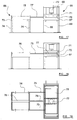
Figure 5 is a side view of a filling hopper which is used to fill the mould with particulate material; -
Figure 6 is a plan view from above of the filling hopper; -
Figure 7 is an end view of the hopper in a raised position; -
Figure 8 is a view corresponding to that offigure 7 , but which shows the hopper in a lowered position for filling the mould; -
Figure 9 is a side view of a collection hopper used in the method of the invention to collect unused particulate material from the mould; -
Figure 10 is a top plan view of the collection hopper offigure 9 ; -
Figure 11 is an end view of the collection hopper offigures 9 and 10 ; -
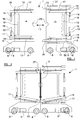
Figure 12 is a side view of a mould carriage used in the method of the present invention; -
Figure 13 is an end view of the mould carriage, showing the mould carriage supporting a mould in a substantially vertical orientation; -
Figure 14 is a view corresponding generally to that offigure 13 , but which shows the mould carriage in an alternate position in which the mould is supported in a substantially horizontal orientation; -
Figure 15 is a top plan view of the mould carriage showing a fan arrangement positioned above the mould; -
Figure 16 is a view corresponding generally to that offigure 15 , but which shows the fan arrangement in an alternate position in which has been moved substantially clear of the mould; -
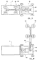
Figure 17 is an end view of a pushing and pressing arrangement used in the method of the present invention; -
Figure 18 is a view corresponding generally to that offigure 17 , but which shows the pusher arrangement in an actuated position effective to push the mould into the press arrangement; -
Figure 19 is a top plan view of the pushing and pressing arrangement in the position illustrated infigure 18 ; -
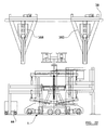
Figure 20 is a side view of an entire apparatus used in the method of the present invention; -
Figure 21 is a top plan view from above of the apparatus illustrated infigure 20 ; and -
Figure 22 is an end view of the apparatus shown infigures 20 and 21 . - The method of the present invention will now be described in detail, with particular reference to the production of substantially flat panels from recycled plastic material. However, it is to be appreciated that the method of the present invention can be used to produce moulded products of other shapes or configurations.
-
Figures 1 to 4 show anoven 1 and amould 2 of a type suitable for use in the method of the present invention. Having particular regard tofigure 1 , theoven 1 comprises twoparts respective carriage arrow 7. The oven is shown infigure 1 in an open configuration in which the two overparts Figure 2 shows the oven in a closed configuration in which the twoparts mould 2. - The
carriages wheels 8 for rolling movement along the ground (for example on cooperating rails) between their open and closed positions by the operation ofelectric motors 9 which are each arranged to drive at least onewheel 8. - Each
oven part more burners 10 positioned within the oven chamber. Gas powered infra-red burners may be used, although it is to be appreciated that other types of burner or heater could be used instead. - Each
oven part lower door 11 and anupper door 12. The lower andupper doors respective pivots figure 1 , and tilted positions.Figure 2 shows the lower door flaps 11 in their tilted positions in which it can be seen that the two door flaps extend generally downwardly from their pivots towards one another. Although not illustrated, it is to be appreciated that the upper door flaps 12 may be moved about their pivots to upwardly tilted positions in which they extend generally upwardly from their pivots towards one another. Eachdoor flap pneumatic cylinder - Each
door flap closure rod 17 mounted for sliding movement along the door flap. Theclosure rods 17 are moved byrespective actuators 18 mounted to the door flaps, the actuators preferably taking the form of hydraulic or pneumatic cylinders. - One of the two over
parts 3 is additionally provided with top and bottom shut-offmembers Figures 1 and 2 both show the two shut-offmembers part 3 on which they are provided. As will be seen fromfigure 2 , when the two overparts mould 2 and the shut-offmembers mould 2 respectively. However, each shut-off member is moveable relative to the housing of the overpart 3 on which they are provided, and can be retracted from their closed positions illustrated to open positions in which they do not project significantly from the housing and hence will not extend above or below the mould when the oven is closed as illustrated infigure 2 . - As illustrated in
figure 4 , the housing of at least one of the overparts 4 is provided with anexhaust outlet 23 in an upper part, the exhaust outlet permitting the exhaust of hot gas from inside the oven chamber. Theexhaust outlet 23 is connectable to an exhaust pipe or duct (not shown). - The
mould 2 is illustrated most clearly infigures 2 and4 . As will be appreciated, the mould is shaped and configured for use in moulding a substantially flat planar panel. The mould comprises a pair ofmould parts mould cavity 26 therebetween. The inner surfaces of themould cavity 26 are preferably coated with a high temperature non-stick coating. Although not illustrated, it is envisaged that themould 2 may be configured to be adjustable in thickness to vary the size of themould cavity 26, thereby facilitating the moulding of panels of different thickness. For example, it is proposed to provide spacers of various sizes for insertion between themould parts - As illustrated in
figures 2 and4 , themould 2 is shown in a moulding position in which it is oriented substantially vertically within the oven chamber, at the interface between the twooven parts mould 2 is configured to be selectively opened at the top and at the bottom when oriented in this manner, and so is provided with top andbottom closures closures closure rods 17 and associatedactuators 18 mounted to the door flaps when the doors flaps are in their horizontal, un-tilted, positions. -
Figures 5 to 8 illustrate ahopper arrangement 29 which is used to fill themould 2 with particulate material, in a manner which will be described in more detail below. The hopper arrangement comprises asupport frame 30 extending between a pair ofhorizontal rails 31. Thesupport frame 30 is moveable along therails 31 via a plurality ofsmall wheels 32 which engage and roll along the rails. - The
support frame 30 comprises a pair of spaced apart end frames 33 which are interconnected by a pair oftransverse beams 34. As shown most clearly infigures 7 and 8 , the end frames 33 are generally triangular in form comprising ahorizontal member 35, a centralvertical member 36, and a pair of diagonal bracingmembers 37. The centralvertical members 36 take the form of elongate channels having a generally C-shaped cross-section, the two channels being arranged so that their open sides face one another across the span between the tworails 31. - A filling
hopper 38 is supported between the two end frames 33. The hopper is configured to hold and dispense particulate material and so has a downwardly tapering form as is conventional. Thehopper 38 is arranged for vertical movement between the two end frames 33, and for this purpose has a pair ofwheels 38 rotatably mounted at each end, thewheels 38 being arranged vertically one above the other. Thewheels 38 are configured to be received within and to run along the C-shaped channels defined by thevertical members 36 of the two end frames 33. Thewheels 38 thus cooperate with thevertical members 36 to guide thehopper 38 for vertical movement between a raised position as illustrated infigure 7 and a lowered position as illustrated infigure 8 . - The
hopper 38 has a plurality ofelongate dispensing tubes 40 which extend vertically downwardly from the narrow lower region of the hopper. The dispensing tubes are arranged in a side-by-side array along the entire length of the hopper and each has a bore sized to permit the substantially free-flow of particulate material. Each tube terminates with anopen dispensing aperture 41 at its lowermost free end. - The flow of particulate material from the chamber of the hopper and down the dispensing
tubes 40 is controlled by arotary valve 42. To help prevent against the particulate material becoming clogged in the hopper chamber of the dispensing tubes, the hopper is provided with a pair ofvibrators 43 in a lower region of the hopper, slightly above the dispensing tubes. -
Figures 9 to 11 illustrate acollection hopper 44 which is used in the method of the invention to collect unused particulate material from themould 2 in a manner which will be explained in more detail below. The collection hopper comprises an upwardly open elongaterectangular housing 45 which is mounted on acarriage 46 havingwheels 47 for rolling movement along the ground, for example along cooperating rails (not shown). In a preferred arrangement, thecollection hopper 44 is self-propelled, and may thus comprises anelectric motor 48 arranged to drive at least one of thewheels 47. -
Figures 12 to 16 illustrate acarriage arrangement 49 configured to support, carry and manipulate themould 2. The carriage arrangement comprises atrolley 50 which is configured for self-propelled movement via wheels 51 and amotor 52. - The
trolley 50 comprises asupport frame 53 which supports ashaft 54 for rotation inbearings 55 about ahorizontal axis 56 spaced above the wheels. Thesupport frame 53 also supports amotor 57 which is operatively connected to theshaft 54 via agearbox 58, the motor thus being operable to rotate theshaft 54 in thebearings 55. - The
shaft 54 supports acantilever support frame 59 for co-rotation therewith, the cantilever frame extending outwardly from thetrolley 50 in spaced relation to the ground. Thecantilever frame 59 is configured to support themould 2, and is shown infigures 12 and 13 supporting themould 2 in a substantially horizontal orientation. However, via operation of themotor 57, theshaft 54 and thecantilever frame 59 can be rotated about theaxis 56 so as to support themould 2 in vertical orientation as previously illustrated infigures 2 ,3 and 4 . Thecantilever frame 59 is shown in this orientation infigure 14 . As will be noted, the cantilever nature of theframe 59 means that regardless of the orientation of the frame and the mould, there is always free space beneath the frame and mould. As will be explained in more detail, this free space is sufficient to permit thecollection hopper 44 to move beneath themould 2 when in its vertical orientation illustrated infigure 14 . - The
trolley 50 also carries anupstanding post 60. Thepost 60 supports agantry 61 for rotation about thevertical axis 62 of the post. Thegantry 61 comprises abeam 63, such as an I-section beam in the case of the particular embodiment illustrated. Thebeam 63 supports an array of coolingfans 64 arranged to direct a cooling flow of air in a generally downwards direction. The coolingfans 64 are preferably provided in the form of ducted units, and may be provided with a supply of water or other liquid coolant so as to produce a fine cooling mist.Figures 12 to 15 all show thegantry 61 and coolingfans 64 positioned vertically above themould 2 supported by thecantilever frame 59. However,figure 16 illustrates the gantry and the cooling fans having been rotated about theaxis 62 by approximately 90 degrees such that they are substantially clear of themould 2. -
Figures 17 to 19 illustrate apressing arrangement 65 and apusher arrangement 66. The pressing arrangement comprises a pressing table 67 which is supported above the ground by a plurality oflegs 68. The table 67 supports a hydraulic orpneumatic press 69 comprising a lower fixedplaten 70 and an uppermoveable platen 71. The twoplatens - The
platens - The upper
moveable platen 71 is mounted for vertical sliding movement under the action of a hydraulic orpneumatic cylinder 72, the cylinder thus being operable to press theupper platen 71 downwardly towards thelower platen 70. The pressing cylinder is configured to apply very high pressing forces to theupper platen 71, for example pressing forces in excess of 100 tonnes. - The
pusher arrangement 66 is located generally adjacent to, but spaced from the pressing arrangement, and similarly comprises a table 73 supported above the ground by a plurality oflegs 74. The table supports horizontal pushingrods 75 which are hydraulically or pneumatically slideable within correspondingcylinders 76, between retracted positions as illustrated infigure 17 , and extended positions as illustrated infigures 18 and 19 in which the pushingrods 75 extend across the gap between the pusher table 73 and the pressing table 67. Infigure 17 , amoulding 77 is shown positioned between thepusher 66 and thepress 65. Infigures 18, and 19 , themoulding 77 is shown having been pushed horizontally by the pushing rods so as to become positioned between theplatens lower platen 70. - The method of the present invention will now be described with reference to
figures 20 to 22 , illustrating a substantially complete system of apparatus comprising the various components described above and illustrated infigures 1 to 19 . - As will be noted with particular reference to
figures 20 and 21 , theoven 1 is positioned generally centrally, below thefilling hopper arrangement 29. Therails 31 of the hopper arrangement are supported above theoven 1, and are arranged so as to be substantially parallel to the direction in which the twooven parts - As illustrated most clearly in
figures 21 and22 , thehopper arrangement 29 actually comprises twodiscrete filling hoppers hoppers - The
first filling hopper 38a is filled with a first particulate material for use in forming the outer skin of a panel product to be moulded via the method of the present invention. The first particulate material comprises recycled plastic material, and preferably consists substantially entirely of recycled plastic material. The recycled plastic material preferably comprises High Impact Polystyrene (HIPS), and may optionally include a die and/or a fire-retardant additive. The grain size of the first particulate material is not thought to be of significant importance to the method, providing that the material can be poured and can flow down the dispensingtubes 40 of thehopper 38a. - The
second filling hopper 38b is filled with a second particulate material for use in forming an inner core of a panel product to be moulded via the method of the present invention. The second particulate material also comprises recycled plastic material, and preferably consists substantially entirely of recycled plastic material. The recycled plastic material preferably comprises High Impact Polystyrene (HIPS), and may optionally include a fire-retardant additive and/or a blowing agent. It is considered preferable for the second particulate material to comprise both HIPS and recycled polyethylene (PE), most preferably in a ratio by weight of 75% HIPS to 25% PE. The addition of PE to the HIPS serves to reduce the melting point of the material. It has been found that a melting point in the region of approximately 140 °C is preferable. Again, the grain size of the second particulate material is not thought to be of significant importance to the method, providing that the material can be poured and can flow down the dispensingtubes 40 of thehopper 38b. - The
collection hopper 44 is arranged for rolling movement along the ground beneath theoven 1, between thewheels 8 at each end of theoven 1. The collection hopper my thus be moved in a direction generally parallel to therails 31. - As illustrated most clearly in
figures 20 and 21 , apressing arrangement 65 and apusher arrangement 66 is provided on each side of theoven 1, each pressing arrangement working in concert with the associated pusher arrangement from respective sides of theoven 1, as will become clear. Also, a pair ofcarriage arrangements 49 are provided; each on a respective side of theoven 1. However, it is to be appreciated that the method could alternatively use just a singlepressing arrangement 65 and associatedpusher 66 andcarriage 49. - A
control panel 78 is operatively connected to all of the various motors, heaters, coolers and actuators, the panel thus controlling the entire moulding process. - A typical moulding cycle appropriate to mould a high-strength panel will now be described.
- Firstly, a
mould 2 is closed by clamping the twomould parts mould cavity 26 therebetween. This is performed on one of thecarriage arrangements 49, most conveniently with itscantilever support frame 59 arranged horizontally. Once themould 2 is securely clamped, thecantilever frame 59 is then rotated through 90 degrees via thecarriage motor 57 so that themould 2 is moved to a substantially vertical orientation. Theoven 1 is then opened by moving the twooven parts figure 1 . With thegantry 61 and the array offans 64 swung clear of themould 2, thecarriage 59 is then advanced towards the oven, moving between thepress 65 and thepusher 66, to move themould 2 into the oven. As will be seen fromfigure 21 , theupstanding post 60 supporting thegantry 61 is sufficiently high for thegantry 61 to move over the top of thepressing arrangement 65 without obstruction. - Once the
mould 2 has been placed inside theoven 1 in the position illustrated infigure 2 , the twoparts mould 2. As will be noted infigures 1 and 2 , eachpart out 79, the two cut-outs cooperating to fit around theshaft 54 of thecarriage arrangement 49. In this manner, theoven 1 can be closed around themould 2 whilst the mould remains supported in the vertical orientation by thecantilever frame 59 of the carriage. - The
bottom closure 28 of themould 2 is then closed by thelower closure rod 17 on the oven. The lower and upper door flaps 11, 12 of the oven are then moved to their horizontal positions in which they close to the bottom and top of themould 2. Theheaters 10 inside the oven are then energised to pre-heat themould 2. The mould is preferably pre-heated in this manner to a temperature in the range of 200 °C to 240 °C, and most preferably 220 °C. - The
filling hopper arrangement 29 is then operated to move thefirst filling hopper 38a to a position vertically above theoven 1. When themould 2 reaches its designated pre-heated temperature, thefirst filling hopper 38a is then lowered along itsvertical members 36 such that the dispensing tubes move into the mould cavity and are lowered towards the bottom of the mould. Thehopper valve 42 is then actuated to fill the mould with the first particulate material. Thevibrators 42 are energised to ensure steady and uninterrupted flow of material down the dispensing tubes. Thehopper 38a is steadily raised along itsvertical members 36 as themould 2 fills with the first particulate material. Once themould 2 is completely filled with the first particulate material, thehopper valve 42 is closed and thehopper 38a is raised and moved clear of the oven to its park position as illustrated infigure 21 . - The
top closure 27 on the mould is then closed by theupper closure rod 17 on the oven and theheaters 10 continue to operate to heat themould 2. During this heating phase, the first particulate material is melted in the regions against the inner surfaces of the twomould parts mould 2. The oven door flaps 11, 12 remain in their substantially horizontal positions during this heating phase, and are thus effectively closed against the top and bottom of themould 2. This prevents significant heating of the top andbottom closures - The mould is typically held at an elevated temperature of approximately 220 °C for a period of 8 minutes during this heating phase, which is effective to form an outer skin of approximately 3 to 4 mm thick against the inner surfaces of the mould. However, longer heating periods may be used if it is desired to form thicker skins.
- During the first heating phase described above, the
collection hopper 44 is moved into a collection position in which it is located immediately below themould 2. - Upon completion of the skin-forming heating phase, the
bottom mould closure 28 is opened and the unmelted particulate material remaining between the two layers of outer skin formed inside the mould is permitted to fall down from themould 2 and into thecollection hopper 44. Thecollection hopper 44 is then moved out from underneath the oven and the particulate material inside can then be returned to thefirst filling hopper 38a, for example via a worm-screw arrangement or the like (not shown). - Once all the unmelted particulate material has been removed from the
mould 2 as described above, thebottom closure 28 of themould 2 is closed and thetop closure 27 is opened. Thesecond filling hopper 38b is then (or simultaneously) moved into to a filling position above themould 2 and is operated as before to fill themould 2 with the second particulate material, between the two layers of skin formed against the opposed surfaces inside themould 2. Thetop mould closure 27 is then closed once again. - The door flaps 11, 12 of the oven are then all moved from their horizontal positions to their tilted positions via operation of their respective actuators on the oven. As will be appreciated from consideration of the tilted lower door flaps 11 shown in
figure 2 , this is effective to permit the hot gases inside the oven to move around the ends of themould 2 and in particular to heat themould closures members - The
heaters 10 then heat themould 2 and the second particulate material therein for a second heating phase, in order to cure the second particulate material and thereby form an inner core of plastic material inside the outer skin. It is proposed that this heating phase will continue for approximately 20 minutes at a temperature of 220 °C. This has been found sufficient to cure the second plastic material when producing a moulding having a thickness of 65 mm. During this heating phase it may be necessary to rotate themould 2 inside the oven via rotation of the supportingcantilever frame 59 on thecarriage 49, in order to ensure even heating throughout the mould so that the entire volume of the second particulate material is cured. - The method steps described above are effective to produce a moulding having a predetermined thickness defined by the size of the
mould 2. However, further steps are necessary to process the moulding into a finished panel. These will now be described. - Following completion of the second heating phase described above, the
oven 1 is opened and themould 2 retrieved via movement of thecarriage arrangement 49 away from the oven. - The next processing steps are performed outside the oven which means that the oven is now free for use in producing another moulding via the operation of the equipment located on the opposite side of the
oven 1, in a similar manner to that described above. - The
mould 2 removed from the oven will be hot and so it is necessary to cool the mould before it can be opened and the moulding inside safely removed for further processing. Thegantry 61 and array offans 64 is thus moved into position above the mould, and the fans are energised to direct a cooling flow of air (and optionally a mist) downwardly and over the mould. Themould 2 may be rotated during this cooling phase. - The
mould 2 is then opened. This is done with the mould supported in a horizontal position between thepusher arrangement 66 and thepressing arrangement 65 by theunderlying cantilever frame 59 as illustrated most clearly infigure 21 . Thegantry 61 may be used as a crane to lift the upper part of themould 25 away from thelower part 24. - The
pusher arrangement 66 is then actuated to slide themoulding 77 into the space between the twoplatens pressing arrangement 65. The pushingrods 75 slide themoulding 77 onto thelower platen 70 and are then retracted back into their park position. - The
pressing arrangement 65 is then actuated to simultaneously cool and compress themoulding 77 between theplatens pressing cylinder 72 is actuated to press theupper platen 71 against the moulding with a pressing force. The pressure applied by the press is preferably in excess of 150 N/cm2. An applied pressure of approximately 190 N/cm2 has been found particularly effective, and in a typical case this will require pressing force of approximately 60 tons. At the same time, the cooling arrangement is operated to pump coolant through the channels inside theplatens moulding 77 as it is being pressed. - The
press 65 is operated to compress themoulding 2 so as to reduce its thickness down to a desired thickness of the finished panel, whilst simultaneously imparting a surface finish to the panel corresponding to any relief pattern formed on the platens. - By way of example, a substantially rectangular (400mm x 700mm)
moulding 77 formed inside themould 2 having an initial thickness of 65 mm, can be compressed down to a thickness in the region of 30 - 50 mm in the press under a pressure of 190 N/cm2, whilst being cooled. The thickness of the moulding is thus typically reduced by 20% or more in the press. It has been found appropriate in the production of such panels to operate the press in this manner whilst cooling the moulding from a starting temperature of approximately 200 °C (following removal from the mould 2) down to approximately 30 - 40 °C over a period of approximately 8 minutes. - Panels manufactured by the above-described process (for example panels having a total thickness of approximately 48 mm and a skin thickness of approximately 3 - 4 mm) have been found to have extremely good structural properties and integrity. It has been found that by producing an
interim moulding 77 of greater thickness and then compressing it to the desired panel thickness whilst simultaneously cooling the moulding/panel results in a significantly improved product when compared to products obtained by the prior art methods. Panels manufactured in accordance with the method of the present invention typically have much improved flatness and integrity. - Whilst the present invention has been described above with specific reference to the use of a pressing arrangement comprising a pair of pressing platens, it is to be appreciated that other types of pressing arrangement could be used without departing from the scope of the claimed invention. For example, it is envisaged that variants of the equipment described above could be used for the method of the invention, and which may incorporate one or more pairs of pressing rollers arranged to apply the required pressing force to the moulding as it is moved through the nip between the or each pair of rollers. Metal rollers are particularly suitable for such an arrangement as they can relatively easily be chilled, for example by the provision of internal fluid channels for the flow of water or other liquid coolant. It is envisaged that one or both of each pair of said rollers would be configured to be urged, for example either pneumatically or hydraulically, towards the oppositely arranged roller to apply the requisite pressing force to the moulding. The external surfaces of one or both of each pair of rollers may have a relief pattern formed therein so as to impress a corresponding pattern into the outer surfaces of a panel to be formed therebetween.
- As will be appreciated, in this alternative type of roller press the moulding will still be simultaneously cooled and compressed so as to reduce its thickness as proposed above. It is envisaged that in order to achieve a sufficient reduction in the thickness of the moulding via use of a roller press, the reduction will need to be achieved over a longer footprint of the equipment which may require more space than in the case of the platen press arrangement discussed above.
- More generally, it is proposed that the pressing equipment suitable for use in the method of this invention could be configured in other ways, the important aspect being that it must be effective to compress the moulding, whilst the moulding is simultaneously cooled, so as to achieve the desired thickness and flatness in the finished product.
- When used in this specification and claims, the terms "comprises" and "comprising" and variations thereof mean that the specified features, steps or integers are included. The terms are not to be interpreted to exclude the presence of other features, steps or integers.
- While the invention has been described in conjunction with the exemplary embodiments described above, many equivalent modifications and variations as defined in the appended claims will be apparent to those skilled in the art.
Claims (15)
- A method for producing a moulded plastic product having an outer skin and in inner core, the method comprising the steps of: providing a mould (2) having a mould cavity (26); forming an outer skin from a first plastic material on at least two opposed surfaces (24,25) inside the mould cavity (26); forming an inner core from a second plastic material inside the mould cavity (26); and at least partially curing the plastic materials to form a moulding (77) inside the mould cavity (26) via the application of heat, the method being characterised by the subsequent steps of simultaneously cooling the moulding (77) and compressing the moulding so as to reduce its size in at least one dimension to a desired dimension of the finished product.
- A method according to claim 1, wherein the moulding (77) is removed from said mould cavity (26) prior to the simultaneous steps of cooling and compressing.
- A method according to claim 2, wherein said simultaneous steps of cooling and compressing are performed in a press (65) having a cooling arrangement configured to cool the moulding (77) whilst in the press (65).
- A method according to any preceding claim, wherein the cooling step is effective to reduce the temperature of the moulding (77) from over 200 °C to under 40 °C.
- A method according to any preceding claim, wherein the compressing step is effective to reduce said dimension by at least 20%.
- A method according to any preceding claim, wherein the compressing step comprises applying a pressure of at least 150 N/cm2 to the moulding (77) for the duration of the cooling step.
- A method according to any preceding claim, wherein said step of forming the outer skin comprises filling the mould cavity (26) with said first plastic material in particulate form, heating the mould (2) to form a skin of melted particulate against said at least two opposed mould surfaces (24,25), and removing un-melted particulate from the mould cavity (26) once a desired thickness of skin has been formed on said surfaces (24,25).
- A method according to claim 7, wherein said step of removing un-melted particulate from the mould cavity (26) is performed by opening an outlet aperture formed in a lower part (28) of the mould (2), and permitting the un-melted particulate material to fall through the outlet aperture under gravity or by turning the mould (2) to pour out the un-melted material.
- A method according to claim 8, wherein said aperture outlet aperture is subsequently closed after removal of the un-melted particulate material, ready for the receipt of said second plastic material in the mould cavity (26).
- A method according to any one of claims 7 to 9, wherein said step of filling the mould cavity (26) with said first plastic material involves pouring said material in particulate form through an inlet aperture formed in an upper part (27) of the mould (2), and subsequently closing said inlet aperture.
- A method according to any preceding claim, wherein said step of forming the inner core comprises filling the mould cavity (26) with said second plastic material in particulate form after the formation of the outer skin on said at least two opposed surfaces (24,25), and heating the mould (2) to at least partially cure substantially the entire volume of said second material inside the mould cavity (26).
- A method according to claim 11, wherein said step of filling the mould cavity with said second plastic material involves pouring said material in particulate form through an inlet aperture formed in an upper part (27) of the mould (2), and subsequently closing said inlet aperture.
- A method according to claim 11 or claim 12, wherein the mould (2) is held at an internal temperature of at least 200 °C for a period of at least 5 minutes.
- A method according to any preceding claim, wherein at least one of said first and second materials comprises recycled High Impact Polystyrene (HIPS).
- A method according to any preceding claim, wherein the second material comprises recycled polyethylene.
Priority Applications (5)
| Application Number | Priority Date | Filing Date | Title |
|---|---|---|---|
| PL11151312T PL2476534T3 (en) | 2011-01-13 | 2011-01-18 | A moulding method |
| EP11151312.3A EP2476534B1 (en) | 2011-01-13 | 2011-01-18 | A moulding method |
| PCT/GB2012/000029 WO2012095635A1 (en) | 2011-01-13 | 2012-01-12 | A moulding method |
| CA2860812A CA2860812C (en) | 2011-01-13 | 2012-01-12 | A moulding method |
| US13/979,347 US8940212B2 (en) | 2011-01-13 | 2012-01-12 | Method for producing a moulded plastic product |
Applications Claiming Priority (2)
| Application Number | Priority Date | Filing Date | Title |
|---|---|---|---|
| EP11150886 | 2011-01-13 | ||
| EP11151312.3A EP2476534B1 (en) | 2011-01-13 | 2011-01-18 | A moulding method |
Publications (2)
| Publication Number | Publication Date |
|---|---|
| EP2476534A1 EP2476534A1 (en) | 2012-07-18 |
| EP2476534B1 true EP2476534B1 (en) | 2014-05-21 |
Family
ID=44904642
Family Applications (1)
| Application Number | Title | Priority Date | Filing Date |
|---|---|---|---|
| EP11151312.3A Active EP2476534B1 (en) | 2011-01-13 | 2011-01-18 | A moulding method |
Country Status (7)
| Country | Link |
|---|---|
| US (1) | US8940212B2 (en) |
| EP (1) | EP2476534B1 (en) |
| CA (1) | CA2860812C (en) |
| DK (1) | DK2476534T3 (en) |
| ES (1) | ES2492516T3 (en) |
| PL (1) | PL2476534T3 (en) |
| WO (1) | WO2012095635A1 (en) |
Families Citing this family (5)
| Publication number | Priority date | Publication date | Assignee | Title |
|---|---|---|---|---|
| GB2500876B8 (en) * | 2012-03-26 | 2016-02-17 | 100 Recycled Panel Company Ltd | A moulding method |
| RU2628392C2 (en) * | 2015-10-20 | 2017-08-16 | Публичное акционерное общество "Транснефть" (ПАО "Транснефть") | Method of manufacturing of spherical two-layer products from polyurethane |
| US10525683B2 (en) * | 2016-11-08 | 2020-01-07 | The Boeing Company | Heated double diaphragm tool for decorative laminate application |
| CN108748773B (en) * | 2018-05-23 | 2020-06-05 | 浙江利帆家具有限公司 | Based on CaCO3Nano SiO2Production equipment and process of modified HDPE furniture material |
| CN113211699B (en) * | 2021-05-10 | 2022-03-25 | 江苏圣泰防腐设备东台有限公司 | Anti-corrosion treatment device and method based on rotational molding process |
Family Cites Families (18)
| Publication number | Priority date | Publication date | Assignee | Title |
|---|---|---|---|---|
| US2802766A (en) * | 1954-02-11 | 1957-08-13 | Roy F Leverenz | Method of manufacturing a laminated article |
| US3366993A (en) * | 1958-05-09 | 1968-02-06 | Jerome H Lemelson | Apparatus for molding |
| ES307132A1 (en) * | 1963-12-19 | 1965-04-01 | Lakeside Plastics Corp | A method for preparing a molding composition. (Machine-translation by Google Translate, not legally binding) |
| US3286004A (en) * | 1964-04-30 | 1966-11-15 | Gen Electric | Method of manufacturing a foam plastic article |
| US3949125A (en) * | 1965-05-14 | 1976-04-06 | Roberts Arthur H | Molded solid plastics articles and a method for their manufacture |
| US4043721A (en) * | 1968-07-11 | 1977-08-23 | Lemelson Jerome H | Composite body molding apparatus |
| US3608007A (en) * | 1968-08-05 | 1971-09-21 | American Seating Co | Method of forming a rigid panel by casting polyurethane in a resin impregnated paper shell |
| US5505886A (en) * | 1992-12-11 | 1996-04-09 | Utah State University Foundation | Process for densification of low density polystyrene |
| JPH06238761A (en) * | 1993-02-16 | 1994-08-30 | Sekisui Plastics Co Ltd | Production of heat insulating panel for building |
| US5972259A (en) * | 1995-09-27 | 1999-10-26 | Hettinga; Siebolt | Method for forming an angled plastic article of varying density |
| JPH10128890A (en) * | 1996-10-31 | 1998-05-19 | Itoki Crebio Corp | Cushion base material as well as cushioning material and its manufacture |
| JP3368197B2 (en) * | 1997-12-26 | 2003-01-20 | 中小企業総合事業団 | High-performance compressed wood manufacturing equipment |
| US6146562A (en) * | 1998-03-13 | 2000-11-14 | Hettinga; Siebolt | Method of injection molding an article with a cellular density distribution which gradually varies between a high density cellular exterior and a low density cellular interior |
| GB2388336C (en) | 2001-02-05 | 2005-07-22 | 3Dm Technologies Inc | Processes for forming plastic, apparatuses for forming plastic, and articles made therefrom |
| US6485800B1 (en) * | 2001-02-07 | 2002-11-26 | Jeld-Wen, Inc. | Articles of composite structure having appearance of wood |
| US6599452B1 (en) * | 2002-06-17 | 2003-07-29 | Bevona, Inc. | Method for manufacturing simulated architectural forms |
| WO2008133535A1 (en) * | 2007-04-30 | 2008-11-06 | Charles Caulder Bree | Rotationally moulded products and moulds |
| GB2466432B (en) * | 2008-12-16 | 2010-11-03 | Crompton Mouldings Ltd | A moulding method and moulding machine |
-
2011
- 2011-01-18 PL PL11151312T patent/PL2476534T3/en unknown
- 2011-01-18 DK DK11151312.3T patent/DK2476534T3/en active
- 2011-01-18 EP EP11151312.3A patent/EP2476534B1/en active Active
- 2011-01-18 ES ES11151312.3T patent/ES2492516T3/en active Active
-
2012
- 2012-01-12 WO PCT/GB2012/000029 patent/WO2012095635A1/en active Application Filing
- 2012-01-12 US US13/979,347 patent/US8940212B2/en not_active Expired - Fee Related
- 2012-01-12 CA CA2860812A patent/CA2860812C/en not_active Expired - Fee Related
Also Published As
| Publication number | Publication date |
|---|---|
| US20130285282A1 (en) | 2013-10-31 |
| CA2860812A1 (en) | 2012-07-19 |
| CA2860812C (en) | 2018-07-03 |
| DK2476534T3 (en) | 2014-08-18 |
| EP2476534A1 (en) | 2012-07-18 |
| ES2492516T3 (en) | 2014-09-09 |
| PL2476534T3 (en) | 2014-10-31 |
| US8940212B2 (en) | 2015-01-27 |
| WO2012095635A1 (en) | 2012-07-19 |
Similar Documents
| Publication | Publication Date | Title |
|---|---|---|
| CA2860812C (en) | A moulding method | |
| US3398434A (en) | Vacuum forming apparatus | |
| EP0502378B1 (en) | Apparatus and method to produce synthetic material skins and objects from plastic | |
| CN105499532A (en) | Wheel mold paint spraying device | |
| CN105397059A (en) | Multi-degree-of-freedom wheel mold paint spraying device | |
| US4012186A (en) | Panel forming device | |
| MXPA02004818A (en) | Thermoforming method and apparatus. | |
| EP3628468B1 (en) | Device for creating supports, formworks, constructions or structures made of foamed plastics | |
| AT408076B (en) | METHOD FOR THE PRODUCTION OF FOAM METAL OR FOAM / METAL COMPOSITE MOLDED BODIES, SYSTEM FOR THE PRODUCTION AND USE THEREOF | |
| EP3037237A1 (en) | Method and apparatus for foaming objects | |
| CN108394058A (en) | A kind of equipment of the wood plastic template in use for architecture of manufacture easy mold release | |
| EP3763502B1 (en) | Apparatus and method for foaming refrigerator cabinets | |
| WO2008101258A1 (en) | Bladder molding systems and methods for fabricating composite articles | |
| DE102009003303B3 (en) | Method for the production of foam glass, comprises supplying a raw mixture from a mixing container over a supply arrangement with uniform scrubber supply on a glass nonwoven strip and/or glass nonwoven segment | |
| CN206030206U (en) | Prefab production line | |
| DE2922314A1 (en) | METHOD AND DEVICE FOR PRODUCING MOLDED BODIES FROM FOAMABLE THERMOPLASTIC PLASTICS | |
| GB2500876A (en) | Moulding Method | |
| CN108943555B (en) | Foaming cooling and material taking automatic production line for foaming plate | |
| CN206030208U (en) | Prefab production line | |
| RU2574619C1 (en) | Moulding process | |
| US3963395A (en) | Mass production line for fabricating structural building members | |
| US20040232601A1 (en) | Continuous twin sheet thermoforming process and apparatus | |
| CN113246282A (en) | Industrialized flow production process of prefabricated part | |
| CN206186076U (en) | Prefab production line | |
| KR102652861B1 (en) | quantity and defect sorting device of films for health functions |
Legal Events
| Date | Code | Title | Description |
|---|---|---|---|
| PUAI | Public reference made under article 153(3) epc to a published international application that has entered the european phase |
Free format text: ORIGINAL CODE: 0009012 |
|
| AK | Designated contracting states |
Kind code of ref document: A1 Designated state(s): AL AT BE BG CH CY CZ DE DK EE ES FI FR GB GR HR HU IE IS IT LI LT LU LV MC MK MT NL NO PL PT RO RS SE SI SK SM TR |
|
| AX | Request for extension of the european patent |
Extension state: BA ME |
|
| 17P | Request for examination filed |
Effective date: 20120730 |
|
| TPAC | Observations filed by third parties |
Free format text: ORIGINAL CODE: EPIDOSNTIPA |
|
| 17Q | First examination report despatched |
Effective date: 20120927 |
|
| RIC1 | Information provided on ipc code assigned before grant |
Ipc: B29C 44/04 20060101ALI20130905BHEP Ipc: B29B 17/00 20060101ALN20130905BHEP Ipc: B29C 44/56 20060101ALN20130905BHEP Ipc: B29C 41/36 20060101ALI20130905BHEP Ipc: B29C 41/18 20060101AFI20130905BHEP |
|
| RIC1 | Information provided on ipc code assigned before grant |
Ipc: B29C 41/18 20060101AFI20131015BHEP Ipc: B29C 44/56 20060101ALN20131015BHEP Ipc: B29C 44/04 20060101ALI20131015BHEP Ipc: B29C 41/36 20060101ALI20131015BHEP Ipc: B29B 17/00 20060101ALN20131015BHEP |
|
| GRAP | Despatch of communication of intention to grant a patent |
Free format text: ORIGINAL CODE: EPIDOSNIGR1 |
|
| INTG | Intention to grant announced |
Effective date: 20131206 |
|
| GRAS | Grant fee paid |
Free format text: ORIGINAL CODE: EPIDOSNIGR3 |
|
| GRAA | (expected) grant |
Free format text: ORIGINAL CODE: 0009210 |
|
| AK | Designated contracting states |
Kind code of ref document: B1 Designated state(s): AL AT BE BG CH CY CZ DE DK EE ES FI FR GB GR HR HU IE IS IT LI LT LU LV MC MK MT NL NO PL PT RO RS SE SI SK SM TR |
|
| REG | Reference to a national code |
Ref country code: GB Ref legal event code: FG4D |
|
| REG | Reference to a national code |
Ref country code: CH Ref legal event code: EP |
|
| REG | Reference to a national code |
Ref country code: AT Ref legal event code: REF Ref document number: 669379 Country of ref document: AT Kind code of ref document: T Effective date: 20140615 |
|
| REG | Reference to a national code |
Ref country code: IE Ref legal event code: FG4D |
|
| REG | Reference to a national code |
Ref country code: DE Ref legal event code: R096 Ref document number: 602011007127 Country of ref document: DE Effective date: 20140710 |
|
| REG | Reference to a national code |
Ref country code: DK Ref legal event code: T3 Effective date: 20140815 |
|
| REG | Reference to a national code |
Ref country code: SE Ref legal event code: TRGR |
|
| REG | Reference to a national code |
Ref country code: ES Ref legal event code: FG2A Ref document number: 2492516 Country of ref document: ES Kind code of ref document: T3 Effective date: 20140909 |
|
| REG | Reference to a national code |
Ref country code: NL Ref legal event code: VDEP Effective date: 20140521 |
|
| REG | Reference to a national code |
Ref country code: NO Ref legal event code: T2 Effective date: 20140521 |
|
| REG | Reference to a national code |
Ref country code: LT Ref legal event code: MG4D |
|
| PG25 | Lapsed in a contracting state [announced via postgrant information from national office to epo] |
Ref country code: GR Free format text: LAPSE BECAUSE OF FAILURE TO SUBMIT A TRANSLATION OF THE DESCRIPTION OR TO PAY THE FEE WITHIN THE PRESCRIBED TIME-LIMIT Effective date: 20140822 Ref country code: LT Free format text: LAPSE BECAUSE OF FAILURE TO SUBMIT A TRANSLATION OF THE DESCRIPTION OR TO PAY THE FEE WITHIN THE PRESCRIBED TIME-LIMIT Effective date: 20140521 Ref country code: IS Free format text: LAPSE BECAUSE OF FAILURE TO SUBMIT A TRANSLATION OF THE DESCRIPTION OR TO PAY THE FEE WITHIN THE PRESCRIBED TIME-LIMIT Effective date: 20140921 |
|
| REG | Reference to a national code |
Ref country code: PL Ref legal event code: T3 |
|
| PG25 | Lapsed in a contracting state [announced via postgrant information from national office to epo] |
Ref country code: HR Free format text: LAPSE BECAUSE OF FAILURE TO SUBMIT A TRANSLATION OF THE DESCRIPTION OR TO PAY THE FEE WITHIN THE PRESCRIBED TIME-LIMIT Effective date: 20140521 Ref country code: RS Free format text: LAPSE BECAUSE OF FAILURE TO SUBMIT A TRANSLATION OF THE DESCRIPTION OR TO PAY THE FEE WITHIN THE PRESCRIBED TIME-LIMIT Effective date: 20140521 Ref country code: LV Free format text: LAPSE BECAUSE OF FAILURE TO SUBMIT A TRANSLATION OF THE DESCRIPTION OR TO PAY THE FEE WITHIN THE PRESCRIBED TIME-LIMIT Effective date: 20140521 |
|
| PG25 | Lapsed in a contracting state [announced via postgrant information from national office to epo] |
Ref country code: PT Free format text: LAPSE BECAUSE OF FAILURE TO SUBMIT A TRANSLATION OF THE DESCRIPTION OR TO PAY THE FEE WITHIN THE PRESCRIBED TIME-LIMIT Effective date: 20140922 |
|
| PG25 | Lapsed in a contracting state [announced via postgrant information from national office to epo] |
Ref country code: SK Free format text: LAPSE BECAUSE OF FAILURE TO SUBMIT A TRANSLATION OF THE DESCRIPTION OR TO PAY THE FEE WITHIN THE PRESCRIBED TIME-LIMIT Effective date: 20140521 Ref country code: EE Free format text: LAPSE BECAUSE OF FAILURE TO SUBMIT A TRANSLATION OF THE DESCRIPTION OR TO PAY THE FEE WITHIN THE PRESCRIBED TIME-LIMIT Effective date: 20140521 Ref country code: BE Free format text: LAPSE BECAUSE OF FAILURE TO SUBMIT A TRANSLATION OF THE DESCRIPTION OR TO PAY THE FEE WITHIN THE PRESCRIBED TIME-LIMIT Effective date: 20140521 Ref country code: RO Free format text: LAPSE BECAUSE OF FAILURE TO SUBMIT A TRANSLATION OF THE DESCRIPTION OR TO PAY THE FEE WITHIN THE PRESCRIBED TIME-LIMIT Effective date: 20140521 Ref country code: CZ Free format text: LAPSE BECAUSE OF FAILURE TO SUBMIT A TRANSLATION OF THE DESCRIPTION OR TO PAY THE FEE WITHIN THE PRESCRIBED TIME-LIMIT Effective date: 20140521 |
|
| REG | Reference to a national code |
Ref country code: DE Ref legal event code: R097 Ref document number: 602011007127 Country of ref document: DE |
|
| PG25 | Lapsed in a contracting state [announced via postgrant information from national office to epo] |
Ref country code: NL Free format text: LAPSE BECAUSE OF FAILURE TO SUBMIT A TRANSLATION OF THE DESCRIPTION OR TO PAY THE FEE WITHIN THE PRESCRIBED TIME-LIMIT Effective date: 20140521 |
|
| PLBE | No opposition filed within time limit |
Free format text: ORIGINAL CODE: 0009261 |
|
| STAA | Information on the status of an ep patent application or granted ep patent |
Free format text: STATUS: NO OPPOSITION FILED WITHIN TIME LIMIT |
|
| 26N | No opposition filed |
Effective date: 20150224 |
|
| REG | Reference to a national code |
Ref country code: DE Ref legal event code: R097 Ref document number: 602011007127 Country of ref document: DE Effective date: 20150224 |
|
| PG25 | Lapsed in a contracting state [announced via postgrant information from national office to epo] |
Ref country code: SI Free format text: LAPSE BECAUSE OF FAILURE TO SUBMIT A TRANSLATION OF THE DESCRIPTION OR TO PAY THE FEE WITHIN THE PRESCRIBED TIME-LIMIT Effective date: 20140521 |
|
| PG25 | Lapsed in a contracting state [announced via postgrant information from national office to epo] |
Ref country code: LU Free format text: LAPSE BECAUSE OF FAILURE TO SUBMIT A TRANSLATION OF THE DESCRIPTION OR TO PAY THE FEE WITHIN THE PRESCRIBED TIME-LIMIT Effective date: 20150118 |
|
| PG25 | Lapsed in a contracting state [announced via postgrant information from national office to epo] |
Ref country code: MC Free format text: LAPSE BECAUSE OF FAILURE TO SUBMIT A TRANSLATION OF THE DESCRIPTION OR TO PAY THE FEE WITHIN THE PRESCRIBED TIME-LIMIT Effective date: 20140521 |
|
| REG | Reference to a national code |
Ref country code: FR Ref legal event code: PLFP Year of fee payment: 6 |
|
| REG | Reference to a national code |
Ref country code: FR Ref legal event code: PLFP Year of fee payment: 7 |
|
| PG25 | Lapsed in a contracting state [announced via postgrant information from national office to epo] |
Ref country code: MT Free format text: LAPSE BECAUSE OF FAILURE TO SUBMIT A TRANSLATION OF THE DESCRIPTION OR TO PAY THE FEE WITHIN THE PRESCRIBED TIME-LIMIT Effective date: 20140521 |
|
| PG25 | Lapsed in a contracting state [announced via postgrant information from national office to epo] |
Ref country code: BG Free format text: LAPSE BECAUSE OF FAILURE TO SUBMIT A TRANSLATION OF THE DESCRIPTION OR TO PAY THE FEE WITHIN THE PRESCRIBED TIME-LIMIT Effective date: 20140521 Ref country code: SM Free format text: LAPSE BECAUSE OF FAILURE TO SUBMIT A TRANSLATION OF THE DESCRIPTION OR TO PAY THE FEE WITHIN THE PRESCRIBED TIME-LIMIT Effective date: 20140521 Ref country code: HU Free format text: LAPSE BECAUSE OF FAILURE TO SUBMIT A TRANSLATION OF THE DESCRIPTION OR TO PAY THE FEE WITHIN THE PRESCRIBED TIME-LIMIT; INVALID AB INITIO Effective date: 20110118 |
|
| PG25 | Lapsed in a contracting state [announced via postgrant information from national office to epo] |
Ref country code: CY Free format text: LAPSE BECAUSE OF FAILURE TO SUBMIT A TRANSLATION OF THE DESCRIPTION OR TO PAY THE FEE WITHIN THE PRESCRIBED TIME-LIMIT Effective date: 20140521 |
|
| REG | Reference to a national code |
Ref country code: FR Ref legal event code: PLFP Year of fee payment: 8 |
|
| PG25 | Lapsed in a contracting state [announced via postgrant information from national office to epo] |
Ref country code: MK Free format text: LAPSE BECAUSE OF FAILURE TO SUBMIT A TRANSLATION OF THE DESCRIPTION OR TO PAY THE FEE WITHIN THE PRESCRIBED TIME-LIMIT Effective date: 20140521 |
|
| PG25 | Lapsed in a contracting state [announced via postgrant information from national office to epo] |
Ref country code: AL Free format text: LAPSE BECAUSE OF FAILURE TO SUBMIT A TRANSLATION OF THE DESCRIPTION OR TO PAY THE FEE WITHIN THE PRESCRIBED TIME-LIMIT Effective date: 20140521 |
|
| PGFP | Annual fee paid to national office [announced via postgrant information from national office to epo] |
Ref country code: SE Payment date: 20191223 Year of fee payment: 10 Ref country code: FI Payment date: 20191220 Year of fee payment: 10 Ref country code: IE Payment date: 20191223 Year of fee payment: 10 |
|
| PGFP | Annual fee paid to national office [announced via postgrant information from national office to epo] |
Ref country code: DK Payment date: 20191223 Year of fee payment: 10 Ref country code: FR Payment date: 20191223 Year of fee payment: 10 |
|
| PGFP | Annual fee paid to national office [announced via postgrant information from national office to epo] |
Ref country code: CH Payment date: 20191223 Year of fee payment: 10 |
|
| PGFP | Annual fee paid to national office [announced via postgrant information from national office to epo] |
Ref country code: NO Payment date: 20191227 Year of fee payment: 10 Ref country code: AT Payment date: 20191220 Year of fee payment: 10 Ref country code: DE Payment date: 20191223 Year of fee payment: 10 Ref country code: PL Payment date: 20200102 Year of fee payment: 10 Ref country code: IT Payment date: 20191223 Year of fee payment: 10 Ref country code: ES Payment date: 20200203 Year of fee payment: 10 |
|
| PGFP | Annual fee paid to national office [announced via postgrant information from national office to epo] |
Ref country code: TR Payment date: 20200110 Year of fee payment: 10 |
|
| PGFP | Annual fee paid to national office [announced via postgrant information from national office to epo] |
Ref country code: GB Payment date: 20210125 Year of fee payment: 11 |
|
| REG | Reference to a national code |
Ref country code: DE Ref legal event code: R119 Ref document number: 602011007127 Country of ref document: DE |
|
| REG | Reference to a national code |
Ref country code: FI Ref legal event code: MAE |
|
| REG | Reference to a national code |
Ref country code: DK Ref legal event code: EBP Effective date: 20210131 |
|
| REG | Reference to a national code |
Ref country code: NO Ref legal event code: MMEP |
|
| REG | Reference to a national code |
Ref country code: CH Ref legal event code: PL Ref country code: SE Ref legal event code: EUG |
|
| REG | Reference to a national code |
Ref country code: AT Ref legal event code: MM01 Ref document number: 669379 Country of ref document: AT Kind code of ref document: T Effective date: 20210118 |
|
| PG25 | Lapsed in a contracting state [announced via postgrant information from national office to epo] |
Ref country code: FI Free format text: LAPSE BECAUSE OF NON-PAYMENT OF DUE FEES Effective date: 20210118 Ref country code: FR Free format text: LAPSE BECAUSE OF NON-PAYMENT OF DUE FEES Effective date: 20210131 Ref country code: AT Free format text: LAPSE BECAUSE OF NON-PAYMENT OF DUE FEES Effective date: 20210118 |
|
| PG25 | Lapsed in a contracting state [announced via postgrant information from national office to epo] |
Ref country code: SE Free format text: LAPSE BECAUSE OF NON-PAYMENT OF DUE FEES Effective date: 20210119 Ref country code: LI Free format text: LAPSE BECAUSE OF NON-PAYMENT OF DUE FEES Effective date: 20210131 Ref country code: NO Free format text: LAPSE BECAUSE OF NON-PAYMENT OF DUE FEES Effective date: 20210131 Ref country code: CH Free format text: LAPSE BECAUSE OF NON-PAYMENT OF DUE FEES Effective date: 20210131 Ref country code: DE Free format text: LAPSE BECAUSE OF NON-PAYMENT OF DUE FEES Effective date: 20210803 |
|
| PG25 | Lapsed in a contracting state [announced via postgrant information from national office to epo] |
Ref country code: DK Free format text: LAPSE BECAUSE OF NON-PAYMENT OF DUE FEES Effective date: 20210131 Ref country code: IE Free format text: LAPSE BECAUSE OF NON-PAYMENT OF DUE FEES Effective date: 20210118 |
|
| REG | Reference to a national code |
Ref country code: ES Ref legal event code: FD2A Effective date: 20220427 |
|
| PG25 | Lapsed in a contracting state [announced via postgrant information from national office to epo] |
Ref country code: IT Free format text: LAPSE BECAUSE OF NON-PAYMENT OF DUE FEES Effective date: 20210118 |
|
| PG25 | Lapsed in a contracting state [announced via postgrant information from national office to epo] |
Ref country code: ES Free format text: LAPSE BECAUSE OF NON-PAYMENT OF DUE FEES Effective date: 20210119 |
|
| GBPC | Gb: european patent ceased through non-payment of renewal fee |
Effective date: 20220118 |
|
| PG25 | Lapsed in a contracting state [announced via postgrant information from national office to epo] |
Ref country code: GB Free format text: LAPSE BECAUSE OF NON-PAYMENT OF DUE FEES Effective date: 20220118 |
|
| PG25 | Lapsed in a contracting state [announced via postgrant information from national office to epo] |
Ref country code: PL Free format text: LAPSE BECAUSE OF NON-PAYMENT OF DUE FEES Effective date: 20210118 |