EP2476356B1 - Stützklappgriff-Anordnung - Google Patents
Stützklappgriff-Anordnung Download PDFInfo
- Publication number
- EP2476356B1 EP2476356B1 EP11151174.7A EP11151174A EP2476356B1 EP 2476356 B1 EP2476356 B1 EP 2476356B1 EP 11151174 A EP11151174 A EP 11151174A EP 2476356 B1 EP2476356 B1 EP 2476356B1
- Authority
- EP
- European Patent Office
- Prior art keywords
- stop
- support
- bearing
- pivot axis
- stop device
- Prior art date
- Legal status (The legal status is an assumption and is not a legal conclusion. Google has not performed a legal analysis and makes no representation as to the accuracy of the status listed.)
- Revoked
Links
Images


Classifications
-
- A—HUMAN NECESSITIES
- A47—FURNITURE; DOMESTIC ARTICLES OR APPLIANCES; COFFEE MILLS; SPICE MILLS; SUCTION CLEANERS IN GENERAL
- A47K—SANITARY EQUIPMENT; ACCESSORIES THEREFOR, e.g. TOILET ACCESSORIES
- A47K17/00—Other sanitary equipment not covered by the other groups of this subclass ; Holders for toilet brushes
- A47K17/02—Body supports, other than seats, for closets, e.g. handles, back-rests, foot-rests; Accessories for closets, e.g. reading tables
- A47K17/022—Wall mounted grab bars or handles, with or without support on the floor
- A47K17/024—Wall mounted grab bars or handles, with or without support on the floor pivotally mounted on the wall
Definitions
- the invention relates to a support folding handle arrangement according to the preamble of claim 1.
- Support folding-handle arrangements of the type mentioned are used as aids in particular in the field of Sanitärcinoplastyen and should allow by their variable configuration in particular elderly and / or handicapped people support or secure their balance when using the sanitary facilities.
- a support folding handle assembly which has a built-in the pivot bearing arrangement case brake that builds on pivoting from the non-use position to the use position increasing braking force up to a blocking of the pivoting movement when reaching the position of use.
- the fall brake not only provides for the construction of a desired increasing braking force, but at the same time upon reaching the blocking position for receiving the respective support torque, which is formed at a load of the handle tube by a person. from that results for the fall brake or for the force-conducting parts of the fall brake at least partially a dimensioning that goes beyond the necessary for receiving the braking force sizing as the possible during operation Abstützmomente this braking force can exceed considerably.
- a support folding handle assembly comprising a first stop means for defining the non-use position and a second stop means for defining the position of use.
- the effective in the non-use position first stop means forms a relatively large moment base
- intended for the use position stop means in which thus actually act large forces on the Schwenklagcranix, due to their design forms a relatively small moment base
- the present invention has for its object to provide a support flap handle assembly with a pivot bearing assembly having stop means, which are designed according to the actual loads, such that the stop means are without significant influence on the external configuration of the support flap handle assembly.
- the support flap handle assembly is constructed so that the second stop means is formed between a free end of a support lever formed by the connector and a support stop formed on the mounting plate and the first stop means is located at a shorter distance from the pivot axis than the second stop means, wherein the first stop device an abutment extension arranged eccentrically to the pivot axis, which cooperates with a correspondingly arranged support stop and is formed by a stop pin aligned parallel to the pivot axis, which engages in a stop groove which extends radially to the pivot axis, wherein an axial groove end with respect to the longitudinal axis of the stop groove forms the support stop ,
- the support flap handle assembly according to the invention thus has functionally differentiated and independently arranged Anschlagcinraumen that can be optimized due to their functional differentiation in terms of their necessary function.
- the first stop device which defines a pivot stop of the support folding handle assembly or the handle tube relative to the mounting wall of the arrangement, only relatively small support moments must absorb, as defined in the non-use position defined by the first stop means, the handle tube against the wall is pivoted and thus no vertical load is exposed.
- the first stop device thus has essentially only the task of allowing a defined distance of the handle tube from the wall in the non-use position, in order to prevent about a striking the handle tube against the wall can.
- a correspondingly small dimensioning of the first stop device can also take place with a relatively small torque base for receiving the support torque, so that a correspondingly small distance between the first stop device and the pivot axis, ie the arrangement of the first stop device in relative proximity to the pivot axis, is possible.
- the first stop device can be arranged due to their thus allowed small dimensions directly in the region of the pivot axis, without affecting the externally perceptible dimensions of the Schwcnklagcranowski, so that in appearance as easily perceptible construction of Schwcnklageran angel is possible.
- the second stop device serves for receiving the support or reaction torque generated by the support load in the use position, so that a large torque base, which is large in comparison to the first stop device, for receiving the corresponding support mechanism is advantageous.
- This torque base is created by the fact that the extending from the pivot axis to the end of the connector portion of the connector is used as a support lever, which is supported on the mounting plate. Since the connecting piece extends between the bearing cheeks, the second stop device is covered to the outside by the bearing cheeks and thus does not change the outer appearance of the support flap handle assembly despite its massive design.
- mounting plate is to be understood not limited to a plate-like configuration, but generally as a Wandan gleich adopted, which allows a rear abutment against the mounting wall.
- the first stop device has an eccentric to the pivot axis arranged Aazzifortsatz, which cooperates with a correspondingly arranged support stop. It is synonymous in principle for the function of the first stop means, whether the stop extension on the bearing cheek and the corresponding support stop on the connector is or vice versa. In any case, the stop extension and the support stop represent small-sized devices that are hardly noticeable from the outside due to their arrangement in relative proximity to the pivot axis.
- the stop extension is formed by a stop pin aligned parallel to the pivot axis, which engages in a stop groove which extends radially to the pivot axis, wherein an axial groove end forms the support stop with respect to the longitudinal axis of the stop groove. Due to the design The first stop device as engaging means with a degree of freedom of movement, a particularly space-saving design of the first stop means is possible.
- the stop groove can be formed independently of the connecting piece, so that the configuration of the connecting piece and in particular the choice of material for the production the connection piece can be made independently of a suitability of the material for forming the stopper groove.
- axle sleeve which is provided with the stop groove, simultaneously serves to receive the pivot axis, so that the formation of the stop groove for the first stop device can take place directly in connection with the processing of the corresponding semi-finished product to form the pivot axis, and in particular the Formation of the axial groove can be made without thereby the need for a further component in addition to the already required for receiving the pivot axis bearing sleeve is required.
- the second stop device has a support stop, which extends as a cross member between the bearing cheeks of the bearing block, so that the support stop simultaneously serves to stabilize or stiffen the bearing cheeks against each other.
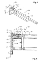
- Fig. 1 shows a support folding handle assembly 20 with a covered by a decorative housing 23 mounting plate 21 (see also Fig. 4 ) and a handle tube assembly 22.
- the mounting plate 21 on its front 26 opposite one Mounting rear wall 27 provided with two parallel and projecting bearing cheeks 28, 29, which form a bearing block 30.
- bearing pin 31, 32 which define a pivot axis 33 is an axle sleeve 34 is provided, which is arranged in a connecting piece 37 which is inserted into a handle tube end 35 of a handle tube 36.
- the connector 37 is provided with a receiving bore 42 for receiving the axle sleeve 34 and also has a pin hole 43 for receiving a locking pin 44 for non-rotatable locking of the axle sleeve 34.
- the connecting piece 37 is provided with a support surface 45 formed by a flattening, with which the connecting piece 37 in the in the Fig. 2 and 4 illustrated use position against a in Fig. 4 shown support stop 46 is applied, which is formed by a between the bearing cheeks 28, 29 of the bearing block 30 extending traverse.
- Fig. 1 to 6 show that the connecting piece 37 or the fitting 37 receiving the handle tube end 35 is provided with a preferably made of plastic decorative housing 47 having a window opening 48 and passage openings 49 for the axle sleeve 34.
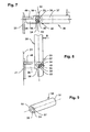
- FIGS. 7 and 8 in the Fig. 9 Shaft 34 shown in an isometric view, which is inserted into the connecting piece 37 such that the Axle sleeve 34, as in Fig. 6 shown with its axial end faces 51 opposite from inner sides 52 of the bearing cheeks 28, 29 is arranged.
- the bearing cheeks 28, 29 have from the inner sides 52 axis parallel to the pivot axis 33 outstanding stop pins 53 which engage in the formation of a first stop means 40 in a stop 54, which are formed in the illustrated embodiment, respectively in the end faces 51 of the axle sleeve 34.
- FIGS. 7 and 8 is for better representation of the engagement conditions in the FIGS. 5 and 6 left bearing cheek 28 shown transparent, wherein the protruding from the inner side 52 of the bearing cheek 28 stop pin 53 in the stopper groove 54 which is formed in the present case approximately kidney-shaped and extends over a quarter circle circumference concentric to the pivot axis 33 engages.
- the stopper groove 54 has two with respect to a longitudinal axis 55 of the stopper 54 axial groove ends 56 and 57. In the in Fig.
- the axle sleeve 34 is pivoted together with the handle tube 36 about the pivot axis 33 until the stop pin 53 against the in Fig. 8 left groove end 56 abuts, so that the groove end 56 defines a corresponding support stop.
- the stop pin 53 is loaded to the maximum with the force arising from the restoring moment shows that is formed by acting on the handle tube 36 restoring force R, which is required to pivot the handle tube 36 against a mounting wall 24, which serves for wall mounting of the mounting plate 21.
- the restoring force R is in any case substantially smaller than the support load L generated by a person supporting himself on the handle tube 36 in the position of use.
Landscapes
- Health & Medical Sciences (AREA)
- Public Health (AREA)
- Epidemiology (AREA)
- General Health & Medical Sciences (AREA)
- Extensible Doors And Revolving Doors (AREA)
Description
- Die Erfindung betrifft eine Stützklappgriff-Anordnung nach dem Oberbegriff des Anspruchs 1.
- Stützklappgriff-Anordnungen der eingangs genannten Art werden als Hilfsmittel insbesondere im Bereich von Sanitärcinrichtungen eingesetzt und sollen durch ihrer variable Konfiguration insbesondere älteren und/oder gehbehinderten Menschen eine Abstützung oder Sicherung ihres Gleichgewichts bei Benutzung der Sanitäreinrichtungen ermöglichen.
- Aus der
EP 1 093 751 A2 ist eine Stützklappgriff-Anordnung bekannt, die über eine in die Schwenklageranordnung integrierte Fallbremse verfügt, die bei Verschwenkung von der Nichtbenutzungsstellung in die Benutzungsstellung eine zunehmende Bremskraft aufbaut bis hin zu einer Blockierung der Schwenkbewegung bei Erreichen der Benutzungsstellung. Bei der bekannten Stützklappgriff-Anordnung sorgt mithin die Fallbremse nicht nur für den Aufbau einer gewünschten zunehmenden Bremskraft, sondern gleichzeitig auch bei Erreichen der Blockierungsstellung für die Aufnahme des jeweiligen Abstützmoment, das bei einer Belastung des Griffsrohres durch eine Person ausgebildet wird. Daraus ergibt sich für die Fallbremse bzw. für die kraftleitenden Teile der Fallbremse zumindest teilweise eine Dimensionierung, die über die zur Aufnahme der Bremskraft notwendige Dimensionierung weit hinausgeht, da die im Betrieb möglichen Abstützmomente diese Bremskraft beträchtlich übersteigen können. - Aus der
GB 2 209 659 - Bei der bekannten Stützklappgriff-Anordnung bildet die in der Nichtbenutzungsstellung wirksame erste Anschlageinrichtung eine relativ große Momentenbasis, wohingegen die für die Benutzungsstellung vorgesehene Anschlageinrichtung, in der also tatsächlich große Kräfte auf die Schwenklagcranordnung wirken, aufgrund ihrer Ausgestaltung eine relativ kleine Momentenbasis ausbildet.
- Der vorliegende Erfindung liegt die Aufgabe zugrunde, eine Stützklappgriff-Anordnung mit einer Schwenklageranordnung zu ermöglichen, die Anschlageinrichtungen aufweist, die den tatsächlichen Belastungen entsprechend ausgelegt sind, derart, dass die Anschlageinrichtungen ohne wesentlichen Einfluss auf die äußere Gestaltung der Stützklappgriff-Anordnung sind.
- Zur Lösung dieser Aufgabe weist die erfindungsgemäße Stützklappgriff-Anordnung die Merkmale des Anspruchs 1 auf.
- Erfindungsgemäß ist die Stützklappgriff-Anordnung so aufgebaut, dass die zweite Anschlageinrichtung zwischen einem freien Ende eines durch das Anschlussstück gebildeten Stützhebels und einem an der Montageplatte ausgebildeten Stützanschlag ausgebildet ist und sich die erste Anschlageinrichtung in kürzerer Entfernung zur Schwenkachse befindet als die zweite Anschlageinrichtung, wobei die erste Anschlageinrichtung einen exzentrisch zur Schwenkachse angeordneten Anschlagfortsatz aufweist, der mit einem korrespondierend angeordneten Stützanschlag zusammenwirkt und durch einen parallel zur Schwenkachse ausgerichteten Anschlagstift gebildet ist, der in eine Anschlagnut eingreift, die radial zur Schwenkachse verläuft, wobei ein bezüglich der Längachse der Anschlagnut axiales Nutende den Stützanschlag bildet.
- Die erfindungsgemäße Stützklappgriff-Anordnung weist somit funktional differenzierte und unabhängig voneinander angeordnete Anschlagcinrichtungen auf, die aufgrund ihrer funktionalen Differenzierung hinsichtlich ihrer notwendigen Funktion optimiert werden können. Dabei wird davon ausgegangen, dass die erste Anschlageinrichtung, die einen Schwenkanschlag der Stützklappgriff-Anordnung bzw. des Griffrohrs relativ zur Befestigungswand der Anordnung definiert, lediglich relativ geringe Stützmomente aufnehmen muss, da sich in der durch die erste Anschlageinrichtung definierten Nichtbenutzungsstellung das Griffrohr gegen die Wand verschwenkt befindet und somit keiner Stützlast ausgesetzt ist. Die erste Anschlageinrichtung hat somit im Wesentlichen lediglich die Aufgabe, einen definierten Abstand des Griffrohrs von der Wand in der Nichtbenutzungsstellung zu ermöglichen, um etwa ein Anschlagen des Griffrohrs gegen die Wand verhindern zu können. Bei den somit vorherrschenden geringen Kräften kann auch eine entsprechend kleine Dimensionierung der ersten Anschlageinrichtung erfolgen mit einer relativ kleinen Momentenbasis zur Aufnahme des Abstützmoments, sodass ein entsprechend geringer Abstand der ersten Anschlageinrichtung gegenüber der Schwenkachse, also die Anordnung der ersten Anschlageinrichtung in relativer Nähe zur Schwenkachse, möglich ist. Die erste Anschlageinrichtung kann aufgrund ihrer somit ermöglichten kleinen Dimensionierung unmittelbar im Bereich der Schwenkachse angeordnet werden, ohne dass dies Einfluss auf die von außen wahrnehmbare Dimensionierung der Schwcnklagcranordnung hätte, sodass eine in der Anmutung als leicht wahrnehmbare Konstruktion der Schwcnklageranordnung möglich wird.
- Dcmgcgenüber dient die zweite Anschlageinrichtung zur Aufnahme des durch die Stützlast in der Benutzungsstellung erzeugten Stütz- oder Reaktionsmoments, sodass eine im Vergleich zur ersten Anschlageinrichtung große Momentenbasis zur Aufnahme des entsprechenden Abstützmomcnts vorteilhaft ist. Diese Momentenbasis wird dadurch geschaffen, dass das sich von der Schwenkachse bis zum Ende des Anschlussstück erstreckende Teilstück des Anschlussstücks als Stützhebel genutzt wird, der sich an der Montageplatte abstützt. Da sich das Anschlussstück zwischen den Lagerwangen erstreckt, ist die zweite Anschlageinrichtung nach außen von den Lagerwangen abgedeckt und verändert somit trotz ihrer massiven Ausgestaltung nicht die äußere Erscheinung der Stützklappgriff-Anordnung.
- Im Zusammenhang mit der Erfindung ist der Begriff "Montageplatte" nicht beschränkt auf eine plattenförmige Ausgestaltung zu verstehen, sondern allgemein als eine Wandanschlusseinrichtung, die eine rückseitige Anlage an die Befestigungswand ermöglicht.
- Die erste Anschlageinrichtung weist einen exzentrisch zur Schwenkachse angeordneten Aaschlagfortsatz auf, der mit einem korrespondierend angeordneten Stützanschlag zusammenwirkt. Dabei ist es grundsätzlich für die Funktion der ersten Anschlageinrichtung gleichbedeutend, ob sich der Anschlagfortsatz an der Lagerwange und der korrespondierende Stützanschlag am Anschlussstück befindet oder umgekehrt. In jedem Fall stellen der Anschlagfortsatz und der Stützanschlag klein dimensionierte Einrichtungen dar, die aufgrund ihrer Anordnung in relativer Nähe zur Schwenkachse von außen kaum wahrnehmbare sind.
- Als besonders vorteilhaft erweist es sich, wenn der Anschlagfortsatz durch einen parallel zur Schwenkachse ausgerichteten Anschlagstift gebildet ist, der in eine Anschlagnut eingreift, die radial zur Schwenkachse verläuft, wobei ein bezüglich der Längsachse der Anschlagnut axiales Nutende den Stützanschlag bildet. Aufgrund der Ausgestaltung der ersten Anschlageinrichtung als Eingriffseinrichtung mit einem Bewegungsfreiheitsgrad, wird eine besonders platzsparende Ausgestaltung der ersten Anschlageinrichtung ermöglicht.
- Wenn der insbesondere als Anschlagstift ausgebildeter Anschlagfortsatz an einer Lagerwange angeordnet ist und die Anschlagnut in einer Stirnfläche einer auf der Schwenkachse angeordneten Achshülse ausgebildet ist, kann die Ausbildung der Anschlagnut unabhängig vom Anschlussstück erfolgen, sodass die Ausgestaltung des Anschlussstückes und insbesondere die Wahl des Materials zur Herstellung des Anschlussstücks unabhängig von einer Eignung des Materials zur Ausbildung der Anschlagnut erfolgen kann.
- Besonders vorteilhaft ist es, wenn die Achshülse, die mit der Anschlagnut versehen ist, gleichzeitig zur Aufnahme der Schwenkachse dient, sodass die Ausbildung der Anschlagnut für die erste Anschlageinrichtung unmittelbar im Zusammenhang mit der Bearbeitung des entsprechenden Halbzeuges zur Ausbildung der Schwenkachse erfolgen kann und insbesondere die Ausbildung der Achsnut erfolgen kann, ohne dass hierdurch die Notwendigkeit eines weiteren Bauteils neben der ohnehin zur Aufnahme der Schwenkachse benötigten Lagerhülse erforderlich ist.
- Hinsichtlich der Ausgestaltung der zweiten Anschlageinrichtung erweist es sich als besonders vorteilhaft, wenn die zweite Anschlageinrichtung einen Stützanschlag aufweist, der sich als Traverse zwischen den Lagerwangen des Lagerbocks erstreckt, sodass der Stützanschlag gleichzeitig zur Stabilisierung bzw. Versteifung der Lagerwangen gegeneinander dient.
- Nachfolgend wird eine bevorzugte Ausführungsform der Erfindung anhand der Zeichnung näher erläutert.
- Es zeigen:
- Fig. 1
- eine Stützklappgriff-Anordnung in isometrischer Darstellung;
- Fig. 2
- eine vergrößerte Darstellung einer Schwenklageranordnung der in
Fig. 1 dargestellten Stützklappgriff-Anordnung in Benutzungsstellung; - Fig. 3
- die in
Fig. 2 dargestellte Schwenklageranordnung in einer Nichtbenutzungsstellung der Stützklappgriff-Anordnung; - Fig. 4
- eine Schnittdarstellung der in
Fig. 1 dargestellten Stützklappgriff-Anordnung gemäß Schnittlinienverlauf IV-IV inFig. 1 ; - Fig. 5
- eine Schnittdarstellung der in
Fig. 1 dargestellten Stützklappgriff-Anordnung gemäß Schnittlinienverlauf V-V inFig. 1 ; - Fig. 6
- eine Schnittdarstellung der in
Fig. 1 dargestellten Stützklappgriff-Anordnung gemäß Schnittlinienverlauf VI-VI inFig. 5 ; - Fig. 7
- eine vereinfachte Darstellung der Schwenklageranordnung der in Benutzungsstellung befindlichen Stützklappgriff-Anordnung;
- Fig. 8
- die in
Fig. 7 dargestellte Schwenklageranordnung in Nichtbenutzungsstellung der Stützklappgriff-Anordnung; - Fig. 9
- eine isometrische Darstellung einer Achshülse der in den
Fig. 7 und 8 dargestellten Schwenklageranordnungen. -
Fig. 1 zeigt eine Stützklappgriff-Anordnung 20 mit einer von einem Dekorgehäuse 23 abgedeckten Montageplatte 21 (siehe auchFig. 4 ) und einer Griffrohranordnung 22. Wie insbesondere dieFig. 4 und5 zeigen, ist die Montageplatte 21 auf ihrer Vorderseite 26 gegenüberliegend einer Montagerückwand 27 mit zwei parallel zueinander und auskragend angeordneten Lagerwangen 28, 29 versehen, die einen Lagerbock 30 ausbilden. Zur Aufnahme von inFig. 5 dargestellten Lagerbolzen 31, 32, die eine Schwenkachse 33 definieren ist eine Achshülse 34 vorgesehen, die in einem Anschlussstück 37 angeordnet ist, das in ein Griffrohrende 35 eines Griffrohrs 36 eingesetzt ist. - Wie weiterhin den
Fig. 4 bis 6 zu entnehmen ist, ist das Anschlussstück 37 mit einer Aufnahmebohrung 42 zur Aufnahme der Achshülse 34 versehen und weist darüber hinaus zur verdrehsicheren Arretierung der Achshülse 34 eine Stiftbohrung 43 zur Aufnahme eines Arretierstifts 44 auf. An seinem rückwärtigen Ende ist das Anschlussstück 37 mit einer durch eine Abflachung gebildeten Stützfläche 45 versehen, mit der das Anschlussstück 37 in der in denFig. 2 und4 dargestellten Benutzungsstellung abstützend gegen einen inFig. 4 dargestellten Stützanschlag 46 anliegt, der durch eine sich zwischen den Lagerwangen 28, 29 des Lagerbocks 30 erstreckende Traverse gebildet ist. - Die
Fig. 1 bis 6 zeigen, dass das Anschlussstück 37 bzw. das das Anschlussstück 37 aufnehmende Griffrohrende 35 mit einem vorzugsweise aus Kunststoff gefertigten Dekorgehäuse 47 versehen ist, das eine Fensteröffnung 48 und Durchtrittsöffnungen 49 für die Achshülse 34 aufweist. - Zur deutlicheren Darstellung einer zwischen der Montageplatte 21 und dem Griffrohrende 35 bzw. dem Anschlussstück 37 ausgebildeten Schwenklageranordnung 50, die die in
Fig. 2 dargestellte Benutzungsstellung und die inFig. 3 dargestellte Nichtbenutzungsstellung der Stützklappgriff-Anordnung 20 ermöglicht, ist die Schwenklageranordnung 50 abweichend von den Darstellungen in denFig. 2 und 3 in denFig. 7 und 8 jeweils ohne das Dekorgehäuse 23 in Benutzungsstellung (Fig. 7 ) und Nichtbenutzungsstellung (Fig. 8 ) dargestellt. Dabei zeigen dieFig. 7 und 8 , die inFig. 9 in isometrischer Darstellung gezeigte Achshülse 34, die in das Anschlussstück 37 derart eingesetzt ist, dass die Achshülse 34, wie inFig. 6 gezeigt, mit ihren axialen Stirnflächen 51 gegenüberliegend von Innenseiten 52 der Lagerwangen 28, 29 angeordnet ist. Die Lagerwangen 28, 29 weisen aus den Innenseiten 52 achsenparallel zur Schwenkachse 33 hervorragende Anschlagstifte 53 auf, die zur Ausbildung einer ersten Anschlageinrichtung 40 in eine Anschlagnut 54 eingreifen, die bei dem dargestellten Ausführungsbeispiel jeweils in den Stirnflächen 51 der Achshülse 34 ausgebildet sind. - In den
Fig. 7 und 8 ist zur besseren Darstellung der Eingriffsverhältnisse die in denFig. 5 und 6 linke Lagerwange 28 transparent dargestellt, wobei der aus der Innenseite 52 der Lagerwange 28 hervorragende Anschlagstift 53 in die Anschlagnut 54, die im vorliegenden Fall etwa nierenförmig ausgebildet ist und sich über einen Viertelkreisumfang konzentrisch zur Schwenkachse 33 erstreckt, eingreift. Die Anschlagnut 54 weist zwei bezüglich einer Längsachse 55 der Anschlagnut 54 axiale Nutenden 56 und 57 auf. In der inFig. 7 dargestellten Benutzungsstellung der Stützklappgriff-Anordnung 20 stützt sich zur Ausbildung einer zweiten Anschlageinrichtung 41 das Anschlussstück 37 gegen den Stützanschlag 46 der Montageplatte 21 ab, sodass ein zwischen der Schwenkachse 33 und dem Stützanschlag 46 durch das Anschlussstück 37 gebildeter Stützhebel 42 eine Momentenbasis zur Aufnahme eines durch eine Stützlast L um die Schwenkachse 33 wirkenden Belastungsmoments bildet. - In der in
Fig. 7 dargestellten Benutzungsstellung ist der in die Anschlagnut 54 eingreifende Anschlagstift 53 von dem benachbarten Nutende 57 beabstandet und somit unbelastet. - In der in
Fig. 8 dargestellten Nichtbenutzungsstellung ist die Achshülse 34 zusammen mit dem Griffrohr 36 um die Schwenkachse 33 soweit verschwenkt, bis der Anschlagstift 53 gegen das inFig. 8 linke Nutende 56 anliegt, sodass das Nutende 56 einen entsprechenden Stützanschlag definiert. In dieser Nichtbenutzungsstellung ist der Anschlagstift 53 maximal mit der Kraft belastet, die sich aus dem Rückstellmoment ergibt, dass durch die auf das Griffrohr 36 wirkende Rückstellkraft R gebildet wird, die erforderlich ist, um das Griffrohr 36 gegen eine Befestigungswand 24, die zur Wandbefestigung der Montageplatte 21 dient, zu verschwenken. Die Rückstellkraft R ist in jedem Fall wesentlich kleiner als die durch eine sich auf dem Griffrohr 36 in der Benutzungsstellung abstützende Person erzeugte Stützlast L.
Claims (4)
- Stützklappgriff-Anordnung (20) mit einer Montageplatte (21) zur Wandbefestigung der Anordnung, wobei die Montageplatte (21) mit einem Lagerbock (30) zur Ausbildung einer Schwenklageranordnung (50) mit einer Schwenkachse (33) zwischen der Montageplatte (21) und einem Griffrohrende (35) eines Griffrohrs (36) versehen ist, das zwischen einer Nichtbenutzungsstellung, in der sich das Griffrohr (36) in einer gegen eine Befestigungswand (24) verschwenkten Anordnung befindet, und einer Benutzungsstellung, in der das Griffrohr (36) von der Befestigungswand auskragend angeordnet ist, verschwenkbar ist, wobei der Lagerbock (30) zur Ausbildung der Schwenklageranordnung ein am Griffrohrende (35) ausgebildetes Anschlussstück (37) zwischen Lagerwangen (28, 29) aufnimmt, wobei die Schwenklageranordnung eine erste Anschlageinrichtung (40) zur Definition der Nichtbenutzungsstellung und eine zweite Anschlageinrichtung (41) zur Definition der Benutzungsstellung aufweist, wobei die erste Anschlageinrichtung (40) zwischen zumindest einer Lagerwange (28, 29) und dem Anschlussstück (37) ausgebildet ist,
dadurch gekennzeichnet,
dass die zweite Anschlageinrichtung (41) zwischen einem freien Ende eines durch das Anschlussstück (37) gebildeten Stützhebels und einem an der Montageplatte (21) ausgebildeten Stützanschlag (46) ausgebildet ist und sich die erste Anschlageinrichtung (40) in kürzerer Entfernung zur Schwenkachse (33) befindet als die zweite Anschlageinrichtung (41), wobei die erste Anschlageinrichtung (40) einen exzentrisch zur Schwenkachse (33) angeordneten Anschlagfortsatz aufweist, der mit einem korrespondierend angeordneten Stützanschlag zusammenwirkt und durch einen parallel zur Schwenkachse (33) ausgerichteten Anschlagstift (53) gebildet ist, der in eine Anschlagnut (54) eingreift, die radial zur Schwenkachse verläuft, wobei ein bezüglich der Längsachse (55) der Anschlagnut axiales Nutende (56) den Stützanschlag bildet. - Stützklappgriff-Anordnung nach Anspruch 1,
dadurch gekennzeichnet.
dass der Anschlagstift (53) an einer Lagerwange (28) angeordnet ist und die Anschlagnut (54) in einer Stirnfläche (51) einer auf der Schwenkachse (33) angeordneten Achshülse (34) ausgebildet ist. - Stützklappgriff-Anordnung nach Anspruch 2,
dadurch gekennzeichnet,
dass die Achshülse (34) als Lagerhülse zur Aufnahme der Schwenkachse (33) dient. - Stützklappgriff-Anordnung nach einem der vorangehenden Ansprüche,
dadurch gekennzeichnet,
dass der Stützanschlag (46) der zweiten Anschlageinrichtung (41) als eine sich zwischen den Lagerwangen (28, 29) des Lagerbocks (30) erstreckende Traverse ausgebildet ist.
Priority Applications (1)
| Application Number | Priority Date | Filing Date | Title |
|---|---|---|---|
| EP11151174.7A EP2476356B1 (de) | 2011-01-17 | 2011-01-17 | Stützklappgriff-Anordnung |
Applications Claiming Priority (1)
| Application Number | Priority Date | Filing Date | Title |
|---|---|---|---|
| EP11151174.7A EP2476356B1 (de) | 2011-01-17 | 2011-01-17 | Stützklappgriff-Anordnung |
Publications (2)
| Publication Number | Publication Date |
|---|---|
| EP2476356A1 EP2476356A1 (de) | 2012-07-18 |
| EP2476356B1 true EP2476356B1 (de) | 2015-08-19 |
Family
ID=44010153
Family Applications (1)
| Application Number | Title | Priority Date | Filing Date |
|---|---|---|---|
| EP11151174.7A Revoked EP2476356B1 (de) | 2011-01-17 | 2011-01-17 | Stützklappgriff-Anordnung |
Country Status (1)
| Country | Link |
|---|---|
| EP (1) | EP2476356B1 (de) |
Citations (7)
| Publication number | Priority date | Publication date | Assignee | Title |
|---|---|---|---|---|
| DE7629336U1 (de) | 1976-09-20 | 1977-06-08 | Zk-Edelstahlverarbeitung Gmbh & Co Kg, 4353 Oer-Erkenschwick | Stuetze fuer koerperbehinderte als hilfsmittel seitlich des wc einzusetzender stuetzarm fuer rollstuhlfahrer |
| DE8810956U1 (de) | 1988-08-30 | 1988-12-22 | Hans Grimberg Edelstahl GmbH, 4300 Essen | Klappsitz oder Klappgriff |
| GB2209659A (en) | 1987-09-11 | 1989-05-24 | Hockley Plate & Metal Company | Bracket |
| GB2247295A (en) | 1990-08-20 | 1992-02-26 | British Gas Plc | Method and apparatus for positioning components |
| EP1308118A2 (de) | 2001-11-02 | 2003-05-07 | HEWI Heinrich Wilke GmbH | Federgelenk für einen wandgehaltenen Sanitärausstattungsgegenstand |
| DE102009052341B3 (de) | 2009-11-02 | 2011-01-20 | Burkhardt-Schumacher, Susanne | Stützklappgriff |
| DE202010013117U1 (de) | 2010-12-14 | 2011-02-24 | Satek Gmbh | Stützklappgriff |
Family Cites Families (2)
| Publication number | Priority date | Publication date | Assignee | Title |
|---|---|---|---|---|
| GB2247495B (en) * | 1990-08-31 | 1994-01-19 | Nicholls & Clarke Limited | Pivot assembly |
| JP2000278665A (ja) | 1999-03-26 | 2000-10-06 | Sony Corp | 受信装置および方法、並びに提供媒体 |
-
2011
- 2011-01-17 EP EP11151174.7A patent/EP2476356B1/de not_active Revoked
Patent Citations (7)
| Publication number | Priority date | Publication date | Assignee | Title |
|---|---|---|---|---|
| DE7629336U1 (de) | 1976-09-20 | 1977-06-08 | Zk-Edelstahlverarbeitung Gmbh & Co Kg, 4353 Oer-Erkenschwick | Stuetze fuer koerperbehinderte als hilfsmittel seitlich des wc einzusetzender stuetzarm fuer rollstuhlfahrer |
| GB2209659A (en) | 1987-09-11 | 1989-05-24 | Hockley Plate & Metal Company | Bracket |
| DE8810956U1 (de) | 1988-08-30 | 1988-12-22 | Hans Grimberg Edelstahl GmbH, 4300 Essen | Klappsitz oder Klappgriff |
| GB2247295A (en) | 1990-08-20 | 1992-02-26 | British Gas Plc | Method and apparatus for positioning components |
| EP1308118A2 (de) | 2001-11-02 | 2003-05-07 | HEWI Heinrich Wilke GmbH | Federgelenk für einen wandgehaltenen Sanitärausstattungsgegenstand |
| DE102009052341B3 (de) | 2009-11-02 | 2011-01-20 | Burkhardt-Schumacher, Susanne | Stützklappgriff |
| DE202010013117U1 (de) | 2010-12-14 | 2011-02-24 | Satek Gmbh | Stützklappgriff |
Non-Patent Citations (2)
| Title |
|---|
| HERRN MARKUS BAPPERT, EIDESSTATTLICHE VERSICHERUNG |
| PREISLISTE 2006 DER SAM VERTRIEBS GMBH & CO. KG, pages 144 - 145 |
Also Published As
| Publication number | Publication date |
|---|---|
| EP2476356A1 (de) | 2012-07-18 |
Similar Documents
| Publication | Publication Date | Title |
|---|---|---|
| EP2140302B1 (de) | Brillengestell | |
| WO1987007672A1 (fr) | Charniere pour meuble | |
| EP1916367A2 (de) | Kraftfahrzeugtürscharnier | |
| DE102008017019A1 (de) | Gelenkbeschlag für Kraftfahrzeugsitze und mit einer Ronde | |
| DE102006016297B4 (de) | Brillengestell | |
| DE20112976U1 (de) | Schwenkbeschlag | |
| EP3277899B1 (de) | Türgriffanordnung für ein kraftfahrzeug | |
| DE102006048107B4 (de) | Vorrichtung zum Sperren einer Schwenkrichtung eines gegenüber einem Halteelement verschwenkbaren Bauteils | |
| DE10361445B4 (de) | Kraftfahrzeugtürschloss | |
| DE4112133B4 (de) | Hebelwerk | |
| DE102004005866B4 (de) | Entfernbare Türfeststellvorrichtung und Scharnier | |
| DE3203885C2 (de) | Außenliegender, um eine Querachse schwenkbarer Ziehgriff, insbesondere für Kraftfahrzeugtüren | |
| EP3236825A1 (de) | Wc-sitzgarnituranordnung | |
| DE102010023466A1 (de) | Handschutz für eine Waffe | |
| EP2172606A2 (de) | Drückeranordnung | |
| DE102016101466A1 (de) | Fahrradbremse | |
| EP2476356A1 (de) | Stützklappgriff-Anordnung | |
| EP1073819A1 (de) | In ein scharnier integrierte kraftwagentürbremse mit öffnungsendanschlag | |
| AT401828B (de) | Scharniergelenk zwischen einem bügel und einem bügelbacken eines brillengestells | |
| AT404193B (de) | Scharniergelenk zwischen einem bügel und einem bügelbacken einer brille | |
| EP3689676B1 (de) | Lageranordnung für ein fahrzeug mit einem kippauflieger | |
| EP2169152B1 (de) | Schlüssel mit einem ersten und einem zweiten Teil | |
| WO2018103790A1 (de) | Kraftfahrzeugtürschloss | |
| AT502167B1 (de) | Vorrichtung zum anlenken eines lenkers einer dreipunktanlenkung eines traktors | |
| DE102005015541B4 (de) | Kraftfahrzeugscharnier für Türen und Klappen |
Legal Events
| Date | Code | Title | Description |
|---|---|---|---|
| PUAI | Public reference made under article 153(3) epc to a published international application that has entered the european phase |
Free format text: ORIGINAL CODE: 0009012 |
|
| 17P | Request for examination filed |
Effective date: 20110202 |
|
| AK | Designated contracting states |
Kind code of ref document: A1 Designated state(s): AL AT BE BG CH CY CZ DE DK EE ES FI FR GB GR HR HU IE IS IT LI LT LU LV MC MK MT NL NO PL PT RO RS SE SI SK SM TR |
|
| AX | Request for extension of the european patent |
Extension state: BA ME |
|
| GRAP | Despatch of communication of intention to grant a patent |
Free format text: ORIGINAL CODE: EPIDOSNIGR1 |
|
| INTG | Intention to grant announced |
Effective date: 20150317 |
|
| GRAS | Grant fee paid |
Free format text: ORIGINAL CODE: EPIDOSNIGR3 |
|
| GRAA | (expected) grant |
Free format text: ORIGINAL CODE: 0009210 |
|
| AK | Designated contracting states |
Kind code of ref document: B1 Designated state(s): AL AT BE BG CH CY CZ DE DK EE ES FI FR GB GR HR HU IE IS IT LI LT LU LV MC MK MT NL NO PL PT RO RS SE SI SK SM TR |
|
| REG | Reference to a national code |
Ref country code: GB Ref legal event code: FG4D Free format text: NOT ENGLISH |
|
| REG | Reference to a national code |
Ref country code: CH Ref legal event code: EP |
|
| REG | Reference to a national code |
Ref country code: IE Ref legal event code: FG4D Free format text: LANGUAGE OF EP DOCUMENT: GERMAN |
|
| REG | Reference to a national code |
Ref country code: AT Ref legal event code: REF Ref document number: 743174 Country of ref document: AT Kind code of ref document: T Effective date: 20150915 |
|
| REG | Reference to a national code |
Ref country code: DE Ref legal event code: R096 Ref document number: 502011007620 Country of ref document: DE |
|
| REG | Reference to a national code |
Ref country code: CH Ref legal event code: NV Representative=s name: FREI PATENTANWALTSBUERO AG, CH |
|
| REG | Reference to a national code |
Ref country code: LT Ref legal event code: MG4D |
|
| REG | Reference to a national code |
Ref country code: NL Ref legal event code: MP Effective date: 20150819 |
|
| PG25 | Lapsed in a contracting state [announced via postgrant information from national office to epo] |
Ref country code: FI Free format text: LAPSE BECAUSE OF FAILURE TO SUBMIT A TRANSLATION OF THE DESCRIPTION OR TO PAY THE FEE WITHIN THE PRESCRIBED TIME-LIMIT Effective date: 20150819 Ref country code: GR Free format text: LAPSE BECAUSE OF FAILURE TO SUBMIT A TRANSLATION OF THE DESCRIPTION OR TO PAY THE FEE WITHIN THE PRESCRIBED TIME-LIMIT Effective date: 20151120 Ref country code: LV Free format text: LAPSE BECAUSE OF FAILURE TO SUBMIT A TRANSLATION OF THE DESCRIPTION OR TO PAY THE FEE WITHIN THE PRESCRIBED TIME-LIMIT Effective date: 20150819 Ref country code: NO Free format text: LAPSE BECAUSE OF FAILURE TO SUBMIT A TRANSLATION OF THE DESCRIPTION OR TO PAY THE FEE WITHIN THE PRESCRIBED TIME-LIMIT Effective date: 20151119 Ref country code: LT Free format text: LAPSE BECAUSE OF FAILURE TO SUBMIT A TRANSLATION OF THE DESCRIPTION OR TO PAY THE FEE WITHIN THE PRESCRIBED TIME-LIMIT Effective date: 20150819 |
|
| PG25 | Lapsed in a contracting state [announced via postgrant information from national office to epo] |
Ref country code: ES Free format text: LAPSE BECAUSE OF FAILURE TO SUBMIT A TRANSLATION OF THE DESCRIPTION OR TO PAY THE FEE WITHIN THE PRESCRIBED TIME-LIMIT Effective date: 20150819 Ref country code: PT Free format text: LAPSE BECAUSE OF FAILURE TO SUBMIT A TRANSLATION OF THE DESCRIPTION OR TO PAY THE FEE WITHIN THE PRESCRIBED TIME-LIMIT Effective date: 20151221 Ref country code: SE Free format text: LAPSE BECAUSE OF FAILURE TO SUBMIT A TRANSLATION OF THE DESCRIPTION OR TO PAY THE FEE WITHIN THE PRESCRIBED TIME-LIMIT Effective date: 20150819 Ref country code: RS Free format text: LAPSE BECAUSE OF FAILURE TO SUBMIT A TRANSLATION OF THE DESCRIPTION OR TO PAY THE FEE WITHIN THE PRESCRIBED TIME-LIMIT Effective date: 20150819 Ref country code: PL Free format text: LAPSE BECAUSE OF FAILURE TO SUBMIT A TRANSLATION OF THE DESCRIPTION OR TO PAY THE FEE WITHIN THE PRESCRIBED TIME-LIMIT Effective date: 20150819 Ref country code: IS Free format text: LAPSE BECAUSE OF FAILURE TO SUBMIT A TRANSLATION OF THE DESCRIPTION OR TO PAY THE FEE WITHIN THE PRESCRIBED TIME-LIMIT Effective date: 20151219 |
|
| PG25 | Lapsed in a contracting state [announced via postgrant information from national office to epo] |
Ref country code: NL Free format text: LAPSE BECAUSE OF FAILURE TO SUBMIT A TRANSLATION OF THE DESCRIPTION OR TO PAY THE FEE WITHIN THE PRESCRIBED TIME-LIMIT Effective date: 20150819 |
|
| PG25 | Lapsed in a contracting state [announced via postgrant information from national office to epo] |
Ref country code: DK Free format text: LAPSE BECAUSE OF FAILURE TO SUBMIT A TRANSLATION OF THE DESCRIPTION OR TO PAY THE FEE WITHIN THE PRESCRIBED TIME-LIMIT Effective date: 20150819 Ref country code: EE Free format text: LAPSE BECAUSE OF FAILURE TO SUBMIT A TRANSLATION OF THE DESCRIPTION OR TO PAY THE FEE WITHIN THE PRESCRIBED TIME-LIMIT Effective date: 20150819 Ref country code: SK Free format text: LAPSE BECAUSE OF FAILURE TO SUBMIT A TRANSLATION OF THE DESCRIPTION OR TO PAY THE FEE WITHIN THE PRESCRIBED TIME-LIMIT Effective date: 20150819 Ref country code: CZ Free format text: LAPSE BECAUSE OF FAILURE TO SUBMIT A TRANSLATION OF THE DESCRIPTION OR TO PAY THE FEE WITHIN THE PRESCRIBED TIME-LIMIT Effective date: 20150819 |
|
| PGFP | Annual fee paid to national office [announced via postgrant information from national office to epo] |
Ref country code: CH Payment date: 20160121 Year of fee payment: 6 |
|
| REG | Reference to a national code |
Ref country code: DE Ref legal event code: R026 Ref document number: 502011007620 Country of ref document: DE |
|
| PLBI | Opposition filed |
Free format text: ORIGINAL CODE: 0009260 |
|
| PG25 | Lapsed in a contracting state [announced via postgrant information from national office to epo] |
Ref country code: RO Free format text: LAPSE BECAUSE OF FAILURE TO SUBMIT A TRANSLATION OF THE DESCRIPTION OR TO PAY THE FEE WITHIN THE PRESCRIBED TIME-LIMIT Effective date: 20150819 Ref country code: BE Free format text: LAPSE BECAUSE OF NON-PAYMENT OF DUE FEES Effective date: 20160131 |
|
| PLAX | Notice of opposition and request to file observation + time limit sent |
Free format text: ORIGINAL CODE: EPIDOSNOBS2 |
|
| 26 | Opposition filed |
Opponent name: EMCO BAD GMBH & CO. KG Effective date: 20160519 |
|
| PG25 | Lapsed in a contracting state [announced via postgrant information from national office to epo] |
Ref country code: LU Free format text: LAPSE BECAUSE OF FAILURE TO SUBMIT A TRANSLATION OF THE DESCRIPTION OR TO PAY THE FEE WITHIN THE PRESCRIBED TIME-LIMIT Effective date: 20160117 Ref country code: SI Free format text: LAPSE BECAUSE OF FAILURE TO SUBMIT A TRANSLATION OF THE DESCRIPTION OR TO PAY THE FEE WITHIN THE PRESCRIBED TIME-LIMIT Effective date: 20150819 |
|
| GBPC | Gb: european patent ceased through non-payment of renewal fee |
Effective date: 20160117 |
|
| PG25 | Lapsed in a contracting state [announced via postgrant information from national office to epo] |
Ref country code: MC Free format text: LAPSE BECAUSE OF FAILURE TO SUBMIT A TRANSLATION OF THE DESCRIPTION OR TO PAY THE FEE WITHIN THE PRESCRIBED TIME-LIMIT Effective date: 20150819 |
|
| REG | Reference to a national code |
Ref country code: FR Ref legal event code: ST Effective date: 20160930 |
|
| PG25 | Lapsed in a contracting state [announced via postgrant information from national office to epo] |
Ref country code: GB Free format text: LAPSE BECAUSE OF NON-PAYMENT OF DUE FEES Effective date: 20160117 |
|
| REG | Reference to a national code |
Ref country code: IE Ref legal event code: MM4A |
|
| PLBB | Reply of patent proprietor to notice(s) of opposition received |
Free format text: ORIGINAL CODE: EPIDOSNOBS3 |
|
| PG25 | Lapsed in a contracting state [announced via postgrant information from national office to epo] |
Ref country code: FR Free format text: LAPSE BECAUSE OF NON-PAYMENT OF DUE FEES Effective date: 20160201 |
|
| PG25 | Lapsed in a contracting state [announced via postgrant information from national office to epo] |
Ref country code: IE Free format text: LAPSE BECAUSE OF NON-PAYMENT OF DUE FEES Effective date: 20160117 |
|
| PG25 | Lapsed in a contracting state [announced via postgrant information from national office to epo] |
Ref country code: IT Free format text: LAPSE BECAUSE OF NON-PAYMENT OF DUE FEES Effective date: 20160117 |
|
| PGFP | Annual fee paid to national office [announced via postgrant information from national office to epo] |
Ref country code: AT Payment date: 20170120 Year of fee payment: 7 |
|
| PG25 | Lapsed in a contracting state [announced via postgrant information from national office to epo] |
Ref country code: MT Free format text: LAPSE BECAUSE OF FAILURE TO SUBMIT A TRANSLATION OF THE DESCRIPTION OR TO PAY THE FEE WITHIN THE PRESCRIBED TIME-LIMIT Effective date: 20150819 |
|
| REG | Reference to a national code |
Ref country code: CH Ref legal event code: PL |
|
| PG25 | Lapsed in a contracting state [announced via postgrant information from national office to epo] |
Ref country code: CH Free format text: LAPSE BECAUSE OF NON-PAYMENT OF DUE FEES Effective date: 20170131 Ref country code: LI Free format text: LAPSE BECAUSE OF NON-PAYMENT OF DUE FEES Effective date: 20170131 |
|
| PGFP | Annual fee paid to national office [announced via postgrant information from national office to epo] |
Ref country code: DE Payment date: 20180321 Year of fee payment: 8 |
|
| PG25 | Lapsed in a contracting state [announced via postgrant information from national office to epo] |
Ref country code: SM Free format text: LAPSE BECAUSE OF FAILURE TO SUBMIT A TRANSLATION OF THE DESCRIPTION OR TO PAY THE FEE WITHIN THE PRESCRIBED TIME-LIMIT Effective date: 20150819 Ref country code: HU Free format text: LAPSE BECAUSE OF FAILURE TO SUBMIT A TRANSLATION OF THE DESCRIPTION OR TO PAY THE FEE WITHIN THE PRESCRIBED TIME-LIMIT; INVALID AB INITIO Effective date: 20110117 Ref country code: CY Free format text: LAPSE BECAUSE OF FAILURE TO SUBMIT A TRANSLATION OF THE DESCRIPTION OR TO PAY THE FEE WITHIN THE PRESCRIBED TIME-LIMIT Effective date: 20150819 |
|
| PG25 | Lapsed in a contracting state [announced via postgrant information from national office to epo] |
Ref country code: MK Free format text: LAPSE BECAUSE OF FAILURE TO SUBMIT A TRANSLATION OF THE DESCRIPTION OR TO PAY THE FEE WITHIN THE PRESCRIBED TIME-LIMIT Effective date: 20150819 Ref country code: TR Free format text: LAPSE BECAUSE OF FAILURE TO SUBMIT A TRANSLATION OF THE DESCRIPTION OR TO PAY THE FEE WITHIN THE PRESCRIBED TIME-LIMIT Effective date: 20150819 Ref country code: HR Free format text: LAPSE BECAUSE OF FAILURE TO SUBMIT A TRANSLATION OF THE DESCRIPTION OR TO PAY THE FEE WITHIN THE PRESCRIBED TIME-LIMIT Effective date: 20150819 |
|
| PG25 | Lapsed in a contracting state [announced via postgrant information from national office to epo] |
Ref country code: BG Free format text: LAPSE BECAUSE OF FAILURE TO SUBMIT A TRANSLATION OF THE DESCRIPTION OR TO PAY THE FEE WITHIN THE PRESCRIBED TIME-LIMIT Effective date: 20150819 |
|
| REG | Reference to a national code |
Ref country code: AT Ref legal event code: MM01 Ref document number: 743174 Country of ref document: AT Kind code of ref document: T Effective date: 20180117 |
|
| PG25 | Lapsed in a contracting state [announced via postgrant information from national office to epo] |
Ref country code: AL Free format text: LAPSE BECAUSE OF FAILURE TO SUBMIT A TRANSLATION OF THE DESCRIPTION OR TO PAY THE FEE WITHIN THE PRESCRIBED TIME-LIMIT Effective date: 20150819 |
|
| REG | Reference to a national code |
Ref country code: DE Ref legal event code: R064 Ref document number: 502011007620 Country of ref document: DE Ref country code: DE Ref legal event code: R103 Ref document number: 502011007620 Country of ref document: DE |
|
| PG25 | Lapsed in a contracting state [announced via postgrant information from national office to epo] |
Ref country code: AT Free format text: LAPSE BECAUSE OF NON-PAYMENT OF DUE FEES Effective date: 20180117 |
|
| RDAF | Communication despatched that patent is revoked |
Free format text: ORIGINAL CODE: EPIDOSNREV1 |
|
| STAA | Information on the status of an ep patent application or granted ep patent |
Free format text: STATUS: THE PATENT HAS BEEN GRANTED |
|
| RDAG | Patent revoked |
Free format text: ORIGINAL CODE: 0009271 |
|
| STAA | Information on the status of an ep patent application or granted ep patent |
Free format text: STATUS: PATENT REVOKED |
|
| 27W | Patent revoked |
Effective date: 20181114 |
|
| REG | Reference to a national code |
Ref country code: BE Ref legal event code: MM Effective date: 20160131 |
|
| REG | Reference to a national code |
Ref country code: AT Ref legal event code: MA03 Ref document number: 743174 Country of ref document: AT Kind code of ref document: T Effective date: 20181114 |