EP2474778A1 - Vehicle headlight - Google Patents
Vehicle headlight Download PDFInfo
- Publication number
- EP2474778A1 EP2474778A1 EP10813472A EP10813472A EP2474778A1 EP 2474778 A1 EP2474778 A1 EP 2474778A1 EP 10813472 A EP10813472 A EP 10813472A EP 10813472 A EP10813472 A EP 10813472A EP 2474778 A1 EP2474778 A1 EP 2474778A1
- Authority
- EP
- European Patent Office
- Prior art keywords
- light
- emitting module
- emitting
- circuit unit
- reflector
- Prior art date
- Legal status (The legal status is an assumption and is not a legal conclusion. Google has not performed a legal analysis and makes no representation as to the accuracy of the status listed.)
- Withdrawn
Links
Images


Classifications
-
- F—MECHANICAL ENGINEERING; LIGHTING; HEATING; WEAPONS; BLASTING
- F21—LIGHTING
- F21S—NON-PORTABLE LIGHTING DEVICES; SYSTEMS THEREOF; VEHICLE LIGHTING DEVICES SPECIALLY ADAPTED FOR VEHICLE EXTERIORS
- F21S41/00—Illuminating devices specially adapted for vehicle exteriors, e.g. headlamps
- F21S41/10—Illuminating devices specially adapted for vehicle exteriors, e.g. headlamps characterised by the light source
- F21S41/19—Attachment of light sources or lamp holders
- F21S41/192—Details of lamp holders, terminals or connectors
-
- F—MECHANICAL ENGINEERING; LIGHTING; HEATING; WEAPONS; BLASTING
- F21—LIGHTING
- F21S—NON-PORTABLE LIGHTING DEVICES; SYSTEMS THEREOF; VEHICLE LIGHTING DEVICES SPECIALLY ADAPTED FOR VEHICLE EXTERIORS
- F21S41/00—Illuminating devices specially adapted for vehicle exteriors, e.g. headlamps
- F21S41/10—Illuminating devices specially adapted for vehicle exteriors, e.g. headlamps characterised by the light source
- F21S41/14—Illuminating devices specially adapted for vehicle exteriors, e.g. headlamps characterised by the light source characterised by the type of light source
- F21S41/141—Light emitting diodes [LED]
- F21S41/147—Light emitting diodes [LED] the main emission direction of the LED being angled to the optical axis of the illuminating device
- F21S41/148—Light emitting diodes [LED] the main emission direction of the LED being angled to the optical axis of the illuminating device the main emission direction of the LED being perpendicular to the optical axis
-
- F—MECHANICAL ENGINEERING; LIGHTING; HEATING; WEAPONS; BLASTING
- F21—LIGHTING
- F21S—NON-PORTABLE LIGHTING DEVICES; SYSTEMS THEREOF; VEHICLE LIGHTING DEVICES SPECIALLY ADAPTED FOR VEHICLE EXTERIORS
- F21S41/00—Illuminating devices specially adapted for vehicle exteriors, e.g. headlamps
- F21S41/10—Illuminating devices specially adapted for vehicle exteriors, e.g. headlamps characterised by the light source
- F21S41/14—Illuminating devices specially adapted for vehicle exteriors, e.g. headlamps characterised by the light source characterised by the type of light source
- F21S41/141—Light emitting diodes [LED]
- F21S41/151—Light emitting diodes [LED] arranged in one or more lines
-
- F—MECHANICAL ENGINEERING; LIGHTING; HEATING; WEAPONS; BLASTING
- F21—LIGHTING
- F21Y—INDEXING SCHEME ASSOCIATED WITH SUBCLASSES F21K, F21L, F21S and F21V, RELATING TO THE FORM OR THE KIND OF THE LIGHT SOURCES OR OF THE COLOUR OF THE LIGHT EMITTED
- F21Y2115/00—Light-generating elements of semiconductor light sources
- F21Y2115/10—Light-emitting diodes [LED]
-
- H—ELECTRICITY
- H01—ELECTRIC ELEMENTS
- H01L—SEMICONDUCTOR DEVICES NOT COVERED BY CLASS H10
- H01L2224/00—Indexing scheme for arrangements for connecting or disconnecting semiconductor or solid-state bodies and methods related thereto as covered by H01L24/00
- H01L2224/01—Means for bonding being attached to, or being formed on, the surface to be connected, e.g. chip-to-package, die-attach, "first-level" interconnects; Manufacturing methods related thereto
- H01L2224/42—Wire connectors; Manufacturing methods related thereto
- H01L2224/44—Structure, shape, material or disposition of the wire connectors prior to the connecting process
- H01L2224/45—Structure, shape, material or disposition of the wire connectors prior to the connecting process of an individual wire connector
- H01L2224/45001—Core members of the connector
- H01L2224/45099—Material
- H01L2224/451—Material with a principal constituent of the material being a metal or a metalloid, e.g. boron (B), silicon (Si), germanium (Ge), arsenic (As), antimony (Sb), tellurium (Te) and polonium (Po), and alloys thereof
- H01L2224/45138—Material with a principal constituent of the material being a metal or a metalloid, e.g. boron (B), silicon (Si), germanium (Ge), arsenic (As), antimony (Sb), tellurium (Te) and polonium (Po), and alloys thereof the principal constituent melting at a temperature of greater than or equal to 950°C and less than 1550°C
- H01L2224/45144—Gold (Au) as principal constituent
-
- H—ELECTRICITY
- H01—ELECTRIC ELEMENTS
- H01L—SEMICONDUCTOR DEVICES NOT COVERED BY CLASS H10
- H01L2224/00—Indexing scheme for arrangements for connecting or disconnecting semiconductor or solid-state bodies and methods related thereto as covered by H01L24/00
- H01L2224/01—Means for bonding being attached to, or being formed on, the surface to be connected, e.g. chip-to-package, die-attach, "first-level" interconnects; Manufacturing methods related thereto
- H01L2224/42—Wire connectors; Manufacturing methods related thereto
- H01L2224/47—Structure, shape, material or disposition of the wire connectors after the connecting process
- H01L2224/48—Structure, shape, material or disposition of the wire connectors after the connecting process of an individual wire connector
- H01L2224/4805—Shape
- H01L2224/4809—Loop shape
- H01L2224/48091—Arched
-
- H—ELECTRICITY
- H01—ELECTRIC ELEMENTS
- H01L—SEMICONDUCTOR DEVICES NOT COVERED BY CLASS H10
- H01L2224/00—Indexing scheme for arrangements for connecting or disconnecting semiconductor or solid-state bodies and methods related thereto as covered by H01L24/00
- H01L2224/73—Means for bonding being of different types provided for in two or more of groups H01L2224/10, H01L2224/18, H01L2224/26, H01L2224/34, H01L2224/42, H01L2224/50, H01L2224/63, H01L2224/71
- H01L2224/732—Location after the connecting process
- H01L2224/73251—Location after the connecting process on different surfaces
- H01L2224/73265—Layer and wire connectors
Definitions
- the present invention relates to automotive headlamps and, in particular, to an automotive headlamp equipped with a light-emitting apparatus having a light-emitting module and a control circuit unit for controlling the lighting of the light-emitting module.
- Patent Document 1 Japanese Unexamined Patent Application Publication (Kokai) No. 2005-32661 .
- control circuit units for controlling the lightings of the light-emitting modules, corresponding respectively to the plurality of light-emitting modules, there may be cases that the light path of light irradiated from the automotive headlamps is blocked depending on the arrangement of electronic components constituting the control circuit units.
- the present invention has been made to solve the above-described problems, and a purpose thereof is to avoid a situation that the light path of light used for irradiation is obstructed by a control circuit unit for controlling the lighting of a light-emitting module.
- an automotive headlamp includes: a light-emitting module; a control circuit unit configured to control the lighting of the light-emitting module; a support substrate configured to support both the light-emitting module and the control circuit unit; and a reflector configured to reflect, through an inner surface of the reflector, light emitted by the light-emitting module and collect the reflected light.
- the support substrate is arranged in a manner such that the control circuit unit is positioned in a region outside the reflector.
- the automotive headlamp according to this embodiment may further include an electrically conductive member that electrically connects the light-emitting module and the control circuit unit.
- the electrically conductive member may be connected from a portion of the electrically conductive member connected to the control circuit unit to the light-emitting module, through an installation path that leads to a point more forward in a light-concentrating direction of the reflector than the light-emitting module, in a manner such that a light path of light, collected by the reflector, out of the light emitted by the light-emitting module is avoided.
- the automotive headlamp according to this embodiment may further include a housing mounted on the support substrate.
- the electrically conductive member may be supported by the housing in a manner such that when the housing is mounted on the support substrate, a portion thereof, which is led from at least a neighborhood of the control circuit unit to the point more forward in the light-concentrating direction of the reflector than the light-emitting module, is led to the installation path.
- the electrically conductive member can be easily led and wired in such a manner as to avoid the light path of light used for concentration of light by the reflector.
- the electrically conductive member may be connected to the light-emitting module by an aluminum ribbon that extends forward in the light-concentrating direction of the reflector from the light-emitting module.
- the support substrate may be formed of a heat-radiating material.
- the automotive headlamp may further include a plurality of light-emitting apparatuses each having the light-emitting module, the control circuit unit, and the support substrate.
- Each of the plurality of light-emitting apparatuses may be used to form a different part of a light distribution pattern to be formed.
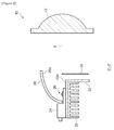
- FIG. 1 shows a structure of an automotive headlamp 10 according to the present embodiment.
- FIG. 2 is a cross-sectional view of FIG. 1 taken along the line P-P. A description is given hereunder of a structure of the automotive headlamps 10 in conjunction with both FIG. 1 and FIG. 2 .
- the automotive headlamp 10 includes a projection lens 12, lens supporting members 14, plates 16, supporting members 22, a light-emitting apparatus 24, a light-emitting module 26, a reflector 28, a shade 30, and a heatsink 32.
- the projection lens 12 is a plano-convex aspheric lens, having a convex front surface and a plane rear surface, which projects a light source image formed on the rear focal plane toward a front area of a lamp as a reverted image.
- a description will be given with reference to projection images which are formed on the virtual vertical screen installed 25 meters, for instance, in front of a vehicle.
- the virtual plane on which the projection images are supposed to be formed is not limited to such a vertical plane only.
- the virtual plane may be a horizontal plane that simulates the road surface.
- the supporting member 22 is formed such that a plate-like member is bent in an L-shape.
- One of outer surfaces of the supporting member 22 is a horizontal top face 22a, whereas the other thereof is oriented forward in a direction vertical to an optical axis X of the projection lens 12.
- the lens supporting member 14 is formed such that a long, thin metal plate is bent in an L-shape.
- the plate 16 is formed of a long, thin metal plate. Both ends of the projection lens 12 in the horizontal direction are secured to the supporting members 22 by way of a pair of lens supporting members 14 and a pair of plates 16, respectively.
- Three light-emitting apparatuses 24 are provided on the top face 22a so that these light-emitting apparatuses 24 are arranged side by side along the direction vertical to the optical axis X.
- the three light-emitting apparatuses 24 each has the light-emitting module 26 for emitting white light.
- Each of the three light-emitting apparatuses 24 is arranged such that a lowermost part of a light-emitting section of each light-emitting module 26 coincides with the height of the optical axis X.
- the number of light-emitting apparatuses 24 provided in the automotive headlamp 10 is not limited to three, and note also that a single light-emitting apparatus 24 or a plurality (other than three) of light-emitting apparatuses 24 may be provided in the automotive headlamp 10.
- the reflector 28 is so provided as to cover the light-emitting module 26 of each of the three light-emitting apparatuses 24 from above.
- the reflector 28 has a reflecting surface 28a having three curves surfaces therein so that the reflector 28 can reflect and collect the light emitted by each of the three light-emitting modules 26.
- the reflector 28 reflects the light emitted by each of three light-emitting modules 26 through the reflecting surface 28a and collects the reflected light.
- the shade 30, which is formed in the shape of a plate, is disposed between the light-emitting section of the light-emitting module 26 and the projection 12.
- the shade 30 is arranged so that an upper edge of the shade 30 is positioned on the rear focal plane.
- the shade 30 blocks part of both the light emitted from the light-emitting modules 26 and the light reflected by the reflector 28, thereby forming cutoff lines of a low-beam light distribution pattern described later.
- the heatsink 32 is placed below the supporting member 22.
- the heatsink 32 recovers the heat, generated by the light-emitting apparatuses 24, via the supporting member 22 and releases it to the outside, thereby suppressing the rise in temperature of the light-emitting apparatuses 24.
- FIG. 3 illustrates a light distribution pattern formed on the virtual vertical screen by the automotive headlamps 10 according to the present embodiment.
- a low-beam light distribution pattern PL is formed by the automotive headlamps 10.
- the two automotive headlamps 10 are provided in a left front part and a right front part of a vehicle, respectively.
- the low-beam light distribution pattern PL is formed by this pair of automotive headlamps 10.
- the low-beam distribution pattern PL which is a left-hand low-beam distribution pattern, has a cutoff line CL1 to a cutoff line CL3 at the top end thereof.
- the first cutoff line CL1 to the third cutoff line CL3 are configured as follows. That is, the first cutoff line CL1 and the second cutoff line CL2 extend horizontally in such a manner that the first cutoff line CL1 is stepped down from the second cutoff line CL2 with respect to a vertical line V-V serving as the boundary line therebetween and passing through a vanishing point in a frontal direction of the lamp.
- the first cutoff line CL1 extends horizontally such that the first cutoff line CL1 is located on the right side of the V-V line and is located in a position lower than an H-H line.
- the first cutoff line CL1 is used as a cutoff line on the side of an oncoming traffic lane.
- the cutoff line CL3 extends obliquely from a left end of the first cutoff line CL1 toward upper left at an angle of 45 degrees.
- the cutoff line CL2 is formed such that it extends along the H-H line on the left side from the intersection of the cutoff line CL3 and the H-H.
- the cutoff line CL2 is used as a cutoff line on the side of the driver's own lane.
- the low-beam light distribution pattern PL is configured by the first light distribution pattern PL1, the second light distribution pattern P12, and the third light distribution pattern PL3.
- the first light distribution pattern PL1 constitutes a right side of the V-V line.
- the first light distribution pattern PL1 is formed by the light emitted by the first light-emitting apparatus 24A.
- the second light distribution pattern PL2 constitutes a left side of the V-V line.
- the second light distribution pattern PL2 is formed by the light emitted by the third light-emitting apparatus 24C.
- the third light distribution pattern PL3 constitutes a middle part of PL lying across the V-V line.
- the third light distribution pattern PL3 is formed by the light emitted by the second light-emitting apparatus 24B.
- the light distribution patterns are formed, via the single shade 30 and the projection lens 12, by the use of the light emitted by a plurality of light-emitting apparatuses 24.
- the positions of the cutoff lines can be accurately adjusted as compared with a case where the shades 30 and the projections lenses 12 are provided for a plurality of light-emitting apparatuses 24, respectively.
- the positions of the light-emitting apparatuses 24 can be adjusted with ease.
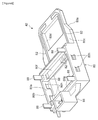
- FIG. 4 is a perspective view of the light-emitting apparatus 24 according to the present embodiment.
- the light-emitting apparatus 24 includes a first unit 40, a second unit 42, and a third unit 44.
- the first unit 40 is provided with the light-emitting module 26.
- the light emitting apparatus 24 is constructed by first placing the second unit 42 on the first unit 40 and then the third unit 44 on top of them.
- FIG. 5A is a perspective view of the first unit 40
- FIG. 5B is a side view of the first unit 40
- FIG. 5C is a top view of the first unit 40.
- a description will be given below of a structure of the first unit 40 by referring to FIGS. 5A to 5C .
- the first unit 40 includes a heat-radiating substrate 50, a light-emitting module 26, and a lower-side circuit unit 60.
- the heat-radiating substrate 50 is shaped in a rectangular plate made of aluminum which is a heat-dissipating material with excellent thermal conductivity. It is to be noted that heat-dissipating material, such as aluminum alloy, copper, or copper alloy, may be used in the place of aluminum.
- a raised portion 50b for placing the light emitting module 26 thereon, which is located near one end of the heat-radiating substrate 50 in the extending direction.
- the lower-side circuit unit 60 is mounted on the upper surface 50a of the heat-radiating substrate 50 near the other end thereof in the extending direction.
- the heat-radiating substrate 50 supports both of the light emitting-module 26 and a control circuit unit 106 on the same side, that is, in positions above the heat-radiating substrate 50.
- the lower-side circuit unit 60 together with a coil to be discussed later, constitutes a lighting control unit for controlling the lighting of the light-emitting module 26.
- the lower-side circuit unit 60 is configured with the electronic components mounted on an alumina substrate 62, which is also a heat-dissipating material with excellent thermal conductivity, by the use of solder or some electrically-conductive adhesive.
- the lower-side circuit unit 60 is firmly fixed to the upper surface 50a of the heat-radiating substrate 50 using an adhesive. At this time, an adhesive which displays a thermal conductivity of 0.5 W/m.K or above and excellent heat radiation is used.
- the light emitting module 26 includes a light-emitting section 52 and a sub-mount 54.
- the sub-mount 54 is shaped in a rectangular plate.
- the light-emitting section 52 is shaped in a rectangular plate.
- the light-emitting module 26 is placed on the raised portion 50b of the heat-radiating substrate 50 in such a manner that the light-emitting section 52 extends perpendicular to the optical axis X of the projector lens 12.
- the light-emitting module 26 is firmly fixed to the heat-radiating substrate 50 by adhesion. At this time, too, an adhesive which displays a thermal conductivity of 2.0 W/m.K or above and excellent heat dissipation is used.
- the light-emitting section 52 has a plurality of semiconductor light emitting elements 56 (four of them in the present embodiment) that emit the white light.
- Each semiconductor light emitting element 56 is formed of a square (1mm ⁇ 1mm) and has an LED.
- the light-emitting section 52 is structured such that the plurality of semiconductor light emitting elements 56 are installed side by side and vertical to the optical axis X. That is, the direction along which the semiconductors 56 are arranged side by side is vertical to the optical axis X.
- the semiconductor light emitting element 56 may have another element-like light source, such as a laser diode, which performs surface emitting in approximately point-like manner.
- the electrode 58 is so provided as to electrically connect a plurality of semiconductor light emitting elements 56 to each other in series or in parallel.
- the heat-radiating substrate 50 supports the light-emitting module 26 and the lower-side circuit unit 60 in such a manner as to recover the heat emanating from each of them.
- This setup enables recovery of heat from both the light-emitting module 26 and the lower-side circuit unit 60 in a simpler structure than the provision of heat-radiating members for them respectively and can also reduce the space that is occupied by such heat-dissipating members.
- the heat-radiating substrate 50 which is formed plane-symmetrically, supports the light-emitting module 26 in such a manner that the center of the light-emitting section 52 is located on the plane of symmetry. This allows the heat-radiating substrate 50 to be used commonly by an automotive headlamp provided on the left side of a vehicle and an automotive headlamp provided on the right side thereof.
- the heat-radiating substrate 50 has a pair of fixation recesses 50c near the raised portion 50b.
- the heat-radiating substrate 50 is secured to the support member 22 with screws that are screwed into the support member 22 passing through the inside of the fixation recesses 50c.
- the pair of fixation recesses 50c is located on a straight line passing through the center of the light-emitting section 52 and perpendicular to the optical axis X. Therefore, the heat-radiating substrate 50 is fixed to the support member 22 at two positions which straddle the center of the light-emitting section 52 on the straight line passing through the center of the light-emitting section 52 of the light-emitting module 26. Provision of the fixation recesses 50c in these positions can prevent the lifting of the heat-radiating substrate 50 from the support member 22 below the light-emitting module 26. Thus the heat produced by the light emitting module 26 is conveyed smoothly to the heatsink 32 through the support member 22. It should be noted that the fixation recesses 50c may be provided on one of the other straight lines passing through the center of the light-emitting section 52.
- the fixation of the heat-radiating substrate 50 to the support member 22 is not limited to that with screws.
- the heat-radiating substrate 50 may be fixed to the support member 22 using rivets, clips, pins, or the like.
- FIG. 6 is a perspective view of the second unit 42.
- the second unit 42 includes a base housing 80, bus bars 82, a connector 86, and bus bars 88.
- the base housing 80 is formed of a resin.
- the base housing 80 is constituted by a plate section 80a and a housing section 80b.
- the bus bars 82 are used to electrically connect the light-emitting module 26 to the lower-side circuit unit 60.
- the bus bars 82 formed in strips of electrically-conductive material such as brass or phosphor bronze, are insert-molded into the base housing 80 to be fixed in an upper surface 80c of the plate section 80a thereof. Therefore, the base housing 80 functions as a support member for the bus bars 82.
- Provided in a middle of the plate section 80a is an opening 80d for receiving the light-emitting module 26 therein.
- the two bus bars 82 are arranged so that each of the two bus bars 82 passes by the opening 80d from the housing section 80b and extends to a position closer to the projector lens 12 than the opening 80d.
- a circuit accommodating area 80e for receiving the lower-side circuit unit 60.
- the circuit accommodating area 80e is formed such that the circuit accommodating area 80e penetrates the housing section 80b vertically.
- a first projecting part 80f and a second projecting part 80g are provided inside the circuit accommodating area 80e.
- the first projecting part 80f is formed such that the first projecting part 80f projects inward within the circuit accommodating area 80e from a wall in contact with the plate section 80a.
- the bus bars 82 are installed such that the bus bars 82 are led from the upper surface 80c of the plate section 80a to an upper surface of the first projecting part 80f.
- the second projecting part 80g is so formed as to project inward within the circuit accommodating area 80e from a wall opposite to the wall on which the first projecting part 80f is disposed.
- the connector 86 for power supply from the outside.
- a bus bar (not shown) connected to a terminal of the connector 86 is led to an upper surface of the second projecting part 80g.
- the bus bars 88 are each formed in an elongate plate bent in an L shape using an electrically-conductive material such as brass or phosphor bronze for weldability.
- the bus bars 88 are disposed at the four corners of the housing section 80b, respectively.
- the bus bars 88 are insert-molded into the base housing 80 to be fixed therein in such a manner as to project upward from the upper surface of the housing section 80b. Two of the four bus bars 88 are led to the upper surface of the first projecting part 80f, whereas the other two thereof are led to the upper surface of the second projecting part 80g.
- the housing section 80b is provided with locking openings 80h in four positions. These locking openings 80h are used to lock a cover housing 100 to the base housing 80.
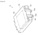
- FIG. 7 is a perspective view of the third unit 44.
- the third unit 44 includes a cover housing 100, a coil 102, and bus bars 104.
- the cover housing 100 is box-shaped with an opening underneath.
- the coil 102 is used as part of the control circuit unit for controlling the lighting of the light-emitting module 26.
- the coil 102 is installed within the cover housing 100. Accordingly, the cover housing 100 functions as a circuit unit support member supporting a part of the control circuit unit.
- the bus bars 104 are each formed in a plate bent in an L shape using an electrically-conductive material such as brass or phosphor bronze for weldability.
- the bus bars 104 are insert-molded into the cover housing 100 such that they are located near the corners of the cover housing 100, respectively.
- the bus bars 104 are electrically connected to the coil 102 inside the cover housing 100.
- the cover housing 100 has four catches 100a.
- the catches 100a are each so formed as to face outward from a position even below the opening of the cover housing 100. With these four catches 100a engaging with the four locking openings 80h provided in the base housing 80 respectively, the third unit 44 is fixed to the second unit 42.
- the four bus bars 104 come in contact with the four bus bars 88 of the second unit 42 respectively.
- the coil 102 and the lower-side circuit unit 60 can be easily connected to each other electrically.
- the bus bars 104 and the bus bars 88 are joined with each other by welding such as laser welding or resistance welding.
- FIG. 8 is a cross-sectional view of the light emitting apparatus 24.
- FIG. 8 shows a cross section of the light emitting apparatus 24 such that the installation path of the bus bar 82 can be observed visually.
- the base housing 80 with the bus bars 82 supported thereon, is mounted on the heat-radiating substrate 50. At this time, the light emitting module 26 is received in the opening 80d of the base housing 80. A spot of the bus bar 82 more forward in the light-concentrating direction of the reflector 28 than the light-emitting module 26 and the electrode 58 of the light-emitting module 26 are connected to each other by an aluminum ribbon 84.
- the light-concentrating direction of the reflector 28 meant here is the direction in which the light emitted by the light-emitting section 52 and reflected by the reflecting surface 28a travels.
- the light-concentrating direction of the reflector 28 is to be understood as the direction of light traveling in parallel with the optical axis X out of the light reflected by the reflecting surface 28a.
- the aluminum ribbon 84 assures connection with larger contact area than with connection by Au wire or the like, which in turn improves the long-term reliability. Also, since the aluminum ribbon 84 has a property resistant to twisting and the like, falling of wire or such trouble in the subsequent processes can be prevented. Also, while the Au wire needs a protective member, the aluminum ribbon 84 does not require such a protective member, so that the manufacturing processes of the light-emitting apparatus 24 and the number of components required therefore can be reduced.
- the bus bar 82, the aluminum ribbon 84, and aluminum ribbon 92 connect the control circuit unit 106 to the light emitting module 26 through an installation path which leads to a spot more forward in the light-concentrating direction of the reflector 28 than the light-emitting module 26 by avoiding the light path used for the concentration of light by the reflector 28 out of the light emitted by the light-emitting module 26.
- the bus bar 82 extends below a region connecting the reflecting surface 28a of the reflector 28 to the light-emitting section 52 of the light-emitting module 26 and is led to a point more forward in the light-concentrating direction of the reflector 28 than the light-emitting module 26.
- the aluminum ribbon 84 connects a forward end in the light-concentrating direction of the thus disposed bus bar 82 to the electrode 58 of the light-emitting module 26.
- the bus bar 82 is supported by the base housing 80 in such a manner that when the base housing 80 is mounted on the heat-radiating substrate 50, the bus bar 82 is led from a neighborhood of the lower-side circuit unit 60 to a point more forward in the light-concentrating direction of the reflector 28 than the light-emitting module 26 by avoiding the light path used for the concentration of light by the reflector 28.
- the obstruction of the light path by the bus bar 82 can be prevented with certainty by fixing the bus bar 82 to the base housing 80 in advance and mounting the base housing 80 on the heat-radiating substrate 50.
- the lower-side circuit unit 60 is received inside the circuit accommodating area 80e of the base housing 80.
- the lower-side circuit unit 60 is connected to the bus bars 82, which are used to connect to the light-emitting module 26, by means of the respective aluminum ribbons 92.
- bus bars 90 for connection with the connector 86.
- the lower-side circuit unit 60 is connected to the bus bars 90 by means of aluminum ribbons 94.
- the lower-side circuit unit 60 is connected to each of the four bus bars 88 via an aluminum ribbon (not shown). It is to be noted that these connections can be made using electrically conductive wire such as Au wire in the place of the aluminum ribbons.
- the cover housing 100 supports the coil 102 in such a manner that when the cover housing is mounted on the second unit 42, the coil 102 received in the circuit accommodating area 100b is placed right above the lower-side circuit unit 60. In this manner, division of the control circuit unit for controlling the lighting of the light-emitting module 26 into a plurality of circuit units and placement of one above the other can reduce the area to be occupied by the control circuit unit.
- the control circuit unit 106 for controlling the lighting of the light-emitting module 26 is comprised of the coil 102 and the lower-side circuit unit 60.
- the light-emitting apparatus 24 is placed on the support member 22 such that the control circuit unit 106 is positioned in a region outside the area having the light-emitting module 26 and the reflector 28 therewithin.
- the control circuit unit 106 for controlling the lighting of the light-emitting module 26 can be structured integrally with the light-emitting module 26, and a situation that the light path is obstructed by the control circuit unit 106 can be prevented.
- the automotive headlamp 10 forms a high-beam light distribution pattern instead of a low-beam light distribution pattern.
- each of the plurality of light-emitting apparatuses 24 is used to form a different part of the high-beam light distribution pattern.
- a vehicle is provided with a lighting control unit for controlling the lighting of each of the light-emitting apparatuses 24.
- the lighting control unit includes a CPU for executing various calculations, a ROM for storing various control programs, and a RAM to be used as work area for storing data and executing programs.
- the lighting control unit acquires image data picked up, for instance, by a CCD (charge-coupled device) camera, determines whether or not there are any vehicles in front by analyzing the data, and identifies the positions of them if there are any vehicles in front. Then the lighting control unit gives a control signal to the light-emitting apparatuses 24 to turn off the light-emitting apparatuses 24 which are forming a divided light distribution pattern including the positions of the vehicles present in front. When such a control signal is inputted, the light-emitting apparatuses 24 turn off the lighting by stopping the supply of electric power to the light-emitting modules 26. At this time, provision of the control circuit unit 106 for each of the light-emitting modules 26 of the light-emitting apparatuses 24 proves effective in controlling the lighting of the light-emitting modules 26 smoothly.
- CCD charge-coupled device
Landscapes
- Engineering & Computer Science (AREA)
- General Engineering & Computer Science (AREA)
- Physics & Mathematics (AREA)
- Microelectronics & Electronic Packaging (AREA)
- Optics & Photonics (AREA)
- Non-Portable Lighting Devices Or Systems Thereof (AREA)
- Arrangement Of Elements, Cooling, Sealing, Or The Like Of Lighting Devices (AREA)
Applications Claiming Priority (2)
| Application Number | Priority Date | Filing Date | Title |
|---|---|---|---|
| JP2009203909 | 2009-09-03 | ||
| PCT/JP2010/005244 WO2011027517A1 (ja) | 2009-09-03 | 2010-08-25 | 車両用前照灯 |
Publications (1)
| Publication Number | Publication Date |
|---|---|
| EP2474778A1 true EP2474778A1 (en) | 2012-07-11 |
Family
ID=43649075
Family Applications (1)
| Application Number | Title | Priority Date | Filing Date |
|---|---|---|---|
| EP10813472A Withdrawn EP2474778A1 (en) | 2009-09-03 | 2010-08-25 | Vehicle headlight |
Country Status (5)
| Country | Link |
|---|---|
| US (1) | US8833992B2 (ja) |
| EP (1) | EP2474778A1 (ja) |
| JP (1) | JPWO2011027517A1 (ja) |
| CN (1) | CN102483208B (ja) |
| WO (1) | WO2011027517A1 (ja) |
Cited By (2)
| Publication number | Priority date | Publication date | Assignee | Title |
|---|---|---|---|---|
| EP2306078A3 (en) * | 2009-10-05 | 2015-11-11 | Koito Manufacturing Co., Ltd. | Vehicle headlamp |
| EP2570716B1 (fr) * | 2011-09-13 | 2022-10-05 | Valeo Vision | Dispositif d'éclairage et/ou de signalisation pour véhicule automobile |
Families Citing this family (8)
| Publication number | Priority date | Publication date | Assignee | Title |
|---|---|---|---|---|
| US8534888B2 (en) * | 2010-09-10 | 2013-09-17 | Koito Manufacturing Co., Ltd. | Optical unit for a vehicular lamp |
| JP5763975B2 (ja) * | 2011-06-03 | 2015-08-12 | 株式会社小糸製作所 | 車両用灯具 |
| US9134003B2 (en) * | 2011-06-13 | 2015-09-15 | Koito Manufacturing Co., Ltd. | Automotive headlamp, heat radiating mechanism, light-emitting apparatus and light source fixing member |
| CN104100925B (zh) * | 2013-04-12 | 2016-12-28 | 海洋王(东莞)照明科技有限公司 | 气体放电灯及其外置遮光板 |
| FR3012204B1 (fr) * | 2013-10-18 | 2015-10-30 | Valeo Vision | Systeme de connexion electrique d'au moins une source de lumiere a un systeme d'alimentation electrique |
| JP6991811B2 (ja) * | 2017-09-25 | 2022-02-03 | 株式会社小糸製作所 | 車両用前照灯 |
| EP3671021A1 (en) * | 2018-12-20 | 2020-06-24 | Valeo Iluminacion, S.A. | Vehicle lamp incorporating means for protection against electrostatic discharges |
| US11655968B2 (en) * | 2020-09-24 | 2023-05-23 | Koito Manufacturing Co., Ltd. | Light-emitting module |
Family Cites Families (13)
| Publication number | Priority date | Publication date | Assignee | Title |
|---|---|---|---|---|
| US4280062A (en) * | 1979-08-22 | 1981-07-21 | Douglas Dynamics Inc. | Auxiliary light wiring harness |
| JP3010518B2 (ja) * | 1994-06-28 | 2000-02-21 | 株式会社小糸製作所 | 車輌用前照灯 |
| JP4496514B2 (ja) * | 2001-07-06 | 2010-07-07 | 株式会社デンソー | 放電灯装置 |
| JP4411892B2 (ja) | 2003-07-09 | 2010-02-10 | 日亜化学工業株式会社 | 光源装置およびこれを用いた車両用前照灯 |
| JP2005044699A (ja) * | 2003-07-24 | 2005-02-17 | Koito Mfg Co Ltd | 車両用灯具及び光源モジュール |
| JP4373822B2 (ja) * | 2004-03-12 | 2009-11-25 | 株式会社小糸製作所 | 光源モジュールおよび車両用灯具 |
| JP2007022479A (ja) * | 2005-07-21 | 2007-02-01 | Mitsuba Corp | 自転車用前照灯 |
| JP2008305641A (ja) * | 2007-06-06 | 2008-12-18 | Koito Mfg Co Ltd | 放電灯点灯装置 |
| JP5069985B2 (ja) | 2007-09-13 | 2012-11-07 | 株式会社小糸製作所 | 車両用前照灯の灯具ユニットおよび車両用前照灯 |
| CN201198290Y (zh) * | 2008-04-09 | 2009-02-25 | 鹤山丽得电子实业有限公司 | 一种led汽车前照灯 |
| JP4523055B2 (ja) * | 2008-08-08 | 2010-08-11 | 株式会社小糸製作所 | 光源モジュールおよび車両用灯具 |
| JP5257665B2 (ja) * | 2008-08-20 | 2013-08-07 | スタンレー電気株式会社 | 車両用前照灯ユニット及び車両用前照灯 |
| JP5457061B2 (ja) * | 2009-04-01 | 2014-04-02 | 株式会社小糸製作所 | 車両用前照灯 |
-
2010
- 2010-08-25 WO PCT/JP2010/005244 patent/WO2011027517A1/ja active Application Filing
- 2010-08-25 JP JP2011529787A patent/JPWO2011027517A1/ja active Pending
- 2010-08-25 US US13/393,777 patent/US8833992B2/en not_active Expired - Fee Related
- 2010-08-25 EP EP10813472A patent/EP2474778A1/en not_active Withdrawn
- 2010-08-25 CN CN201080039217.3A patent/CN102483208B/zh not_active Expired - Fee Related
Non-Patent Citations (1)
| Title |
|---|
| See references of WO2011027517A1 * |
Cited By (2)
| Publication number | Priority date | Publication date | Assignee | Title |
|---|---|---|---|---|
| EP2306078A3 (en) * | 2009-10-05 | 2015-11-11 | Koito Manufacturing Co., Ltd. | Vehicle headlamp |
| EP2570716B1 (fr) * | 2011-09-13 | 2022-10-05 | Valeo Vision | Dispositif d'éclairage et/ou de signalisation pour véhicule automobile |
Also Published As
| Publication number | Publication date |
|---|---|
| WO2011027517A1 (ja) | 2011-03-10 |
| US20120163008A1 (en) | 2012-06-28 |
| CN102483208B (zh) | 2014-07-09 |
| US8833992B2 (en) | 2014-09-16 |
| CN102483208A (zh) | 2012-05-30 |
| JPWO2011027517A1 (ja) | 2013-01-31 |
Similar Documents
| Publication | Publication Date | Title |
|---|---|---|
| EP2474777B1 (en) | Light emitting device and vehicle headlight | |
| US8833992B2 (en) | Automotive headlamps | |
| EP2306078B1 (en) | Vehicle headlamp | |
| JP4343720B2 (ja) | 灯具 | |
| KR101548435B1 (ko) | 회로 모듈, 발광 모듈 및 차량용 등기구 | |
| EP1846692B1 (en) | Light-source module and holder therefor | |
| EP2535638A2 (en) | Automotive headlamp, heat radiating mechanism, light-emitting apparatus and light source fixing member | |
| CN108431489B (zh) | 车辆用灯具 | |
| JP4593661B2 (ja) | 車両用灯具 | |
| CN109424916B (zh) | 灯具单元以及车辆用灯具 | |
| JP6967917B2 (ja) | 灯具ユニット及び車両用灯具 | |
| JP5698081B2 (ja) | 放熱機構および発光装置 | |
| CN114258471A (zh) | 车辆用灯具 | |
| CN209926250U (zh) | 用于车辆的前照灯 | |
| CN109424917B (zh) | 灯具单元及车辆用灯具 |
Legal Events
| Date | Code | Title | Description |
|---|---|---|---|
| PUAI | Public reference made under article 153(3) epc to a published international application that has entered the european phase |
Free format text: ORIGINAL CODE: 0009012 |
|
| 17P | Request for examination filed |
Effective date: 20120329 |
|
| AK | Designated contracting states |
Kind code of ref document: A1 Designated state(s): AL AT BE BG CH CY CZ DE DK EE ES FI FR GB GR HR HU IE IS IT LI LT LU LV MC MK MT NL NO PL PT RO SE SI SK SM TR |
|
| DAX | Request for extension of the european patent (deleted) | ||
| STAA | Information on the status of an ep patent application or granted ep patent |
Free format text: STATUS: THE APPLICATION HAS BEEN WITHDRAWN |
|
| 18W | Application withdrawn |
Effective date: 20141121 |