EP2474427B1 - Tire - Google Patents
Tire Download PDFInfo
- Publication number
- EP2474427B1 EP2474427B1 EP10811545.2A EP10811545A EP2474427B1 EP 2474427 B1 EP2474427 B1 EP 2474427B1 EP 10811545 A EP10811545 A EP 10811545A EP 2474427 B1 EP2474427 B1 EP 2474427B1
- Authority
- EP
- European Patent Office
- Prior art keywords
- recessed
- tire
- shoulder region
- tread
- recessed portion
- Prior art date
- Legal status (The legal status is an assumption and is not a legal conclusion. Google has not performed a legal analysis and makes no representation as to the accuracy of the status listed.)
- Not-in-force
Links
Images



Classifications
-
- B—PERFORMING OPERATIONS; TRANSPORTING
- B60—VEHICLES IN GENERAL
- B60C—VEHICLE TYRES; TYRE INFLATION; TYRE CHANGING; CONNECTING VALVES TO INFLATABLE ELASTIC BODIES IN GENERAL; DEVICES OR ARRANGEMENTS RELATED TO TYRES
- B60C11/00—Tyre tread bands; Tread patterns; Anti-skid inserts
- B60C11/01—Shape of the shoulders between tread and sidewall, e.g. rounded, stepped or cantilevered
-
- B—PERFORMING OPERATIONS; TRANSPORTING
- B60—VEHICLES IN GENERAL
- B60C—VEHICLE TYRES; TYRE INFLATION; TYRE CHANGING; CONNECTING VALVES TO INFLATABLE ELASTIC BODIES IN GENERAL; DEVICES OR ARRANGEMENTS RELATED TO TYRES
- B60C11/00—Tyre tread bands; Tread patterns; Anti-skid inserts
- B60C11/03—Tread patterns
- B60C11/04—Tread patterns in which the raised area of the pattern consists only of continuous circumferential ribs, e.g. zig-zag
-
- B—PERFORMING OPERATIONS; TRANSPORTING
- B60—VEHICLES IN GENERAL
- B60C—VEHICLE TYRES; TYRE INFLATION; TYRE CHANGING; CONNECTING VALVES TO INFLATABLE ELASTIC BODIES IN GENERAL; DEVICES OR ARRANGEMENTS RELATED TO TYRES
- B60C11/00—Tyre tread bands; Tread patterns; Anti-skid inserts
- B60C11/03—Tread patterns
- B60C11/13—Tread patterns characterised by the groove cross-section, e.g. for buttressing or preventing stone-trapping
-
- B—PERFORMING OPERATIONS; TRANSPORTING
- B60—VEHICLES IN GENERAL
- B60C—VEHICLE TYRES; TYRE INFLATION; TYRE CHANGING; CONNECTING VALVES TO INFLATABLE ELASTIC BODIES IN GENERAL; DEVICES OR ARRANGEMENTS RELATED TO TYRES
- B60C13/00—Tyre sidewalls; Protecting, decorating, marking, or the like, thereof
- B60C13/001—Decorating, marking or the like
-
- B—PERFORMING OPERATIONS; TRANSPORTING
- B60—VEHICLES IN GENERAL
- B60C—VEHICLE TYRES; TYRE INFLATION; TYRE CHANGING; CONNECTING VALVES TO INFLATABLE ELASTIC BODIES IN GENERAL; DEVICES OR ARRANGEMENTS RELATED TO TYRES
- B60C5/00—Inflatable pneumatic tyres or inner tubes
-
- B—PERFORMING OPERATIONS; TRANSPORTING
- B60—VEHICLES IN GENERAL
- B60C—VEHICLE TYRES; TYRE INFLATION; TYRE CHANGING; CONNECTING VALVES TO INFLATABLE ELASTIC BODIES IN GENERAL; DEVICES OR ARRANGEMENTS RELATED TO TYRES
- B60C11/00—Tyre tread bands; Tread patterns; Anti-skid inserts
- B60C11/03—Tread patterns
- B60C11/13—Tread patterns characterised by the groove cross-section, e.g. for buttressing or preventing stone-trapping
- B60C11/1353—Tread patterns characterised by the groove cross-section, e.g. for buttressing or preventing stone-trapping with special features of the groove bottom
- B60C2011/1361—Tread patterns characterised by the groove cross-section, e.g. for buttressing or preventing stone-trapping with special features of the groove bottom with protrusions extending from the groove bottom
Definitions
- the present invention relates to a tire having a tread which contacts the road surface, side walls provided on the inner side, in the tire radial direction, of the tread, and a buttress portion provided between the tread and the side walls.
- Patent Document 1 Japanese Unexamined Patent Application Publication No. 2008-24048 (Page 5, Fig. 1 )Reference is also made to EP-A-1074404 , which discloses a tire according to the preamble of Claim 1.
- the buttress portion when the road surface is smooth, the buttress portion does not contact the road surface.
- the buttress portion when there are small dents and bumps on the road surface, such as a paved road with a rough road surface, the buttress portion does contact the road surface, and due to these dents and bumps, the buttress portion vibrates. Vibration of the buttress portion like this increases road noise.
- an object of the present invention is to provide a tire which further reduces road noise by suppressing the generation of road noise due to the vibration of the buttress portion.
- the present invention provides a tire according to Claim 1.
- the recessed shoulder region denotes the portion which does not contact the road surface when the tire is rolling, in a condition where the proper internal pressure and a proper load are applied to the tire.
- the proper internal pressure is the air pressure corresponding to the maximum loading capability set forth in the 2008 edition of the Year Book of the JATMA (Japan Automobile Tyre Manufacturers Association).
- the proper load is the load that corresponds to the maximum loading capability when a single wheel is applied, set forth in the 2008 edition of the Year Book of the JATMA (Japan Automobile Tyre Manufacturers Association ). Outside of Japan, the proper internal pressure is the air pressure corresponding to the maximum load (maximum loading capability) of a single wheel described in the specifications mentioned below.
- the proper load is the maximum load (maximum loading capability) of a single wheel in the applicable size described in the specifications mentioned below.
- the specification is determined by industrial standards effective in regions where the tire is manufactured or used. For example, this would be the "Year Book of The Tire and Rim Association Inc.” in the United States of America, and the “Standards Manual of The European Tire and Rim Technical Organization” in Europe.
- a recessed shoulder region having a predetermined width extends along the tire circumference direction TC, and on the recessed shoulder region, a plurality of recessed portions and a surface portion are formed.
- the generation of road noise due to the vibration of the buttress portion can be suppressed, and a tire further reducing road noise can be provided.
- a pneumatic tire 1 according to a first embodiment will be explained. Specifically, (1) Overall configuration of pneumatic tire, (2) Detailed configuration of recessed shoulder region, (3) Comparative evaluations, (4) Operation and effect, and (5) Modifications will be explained.
- Fig. 1 is a perspective view illustrating a part of the pneumatic tire 1 according to the first embodiment.
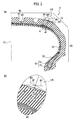
- Fig. 2(a) is a cross-sectional view in the tread width direction of the pneumatic tire 1 according to the first embodiment.
- Fig. 2(b) is an enlarged view illustrating an area enclosed by the double dot and dash line A of Fig. 2(a) .
- the pneumatic tire 1 may be filled with, other than air, an inert gas such as nitrogen gas.
- the pneumatic tire 1 includes a bead portion 10, a carcass 20, an inner liner 30, a belt 40, a tread 50, sidewalls 60, and buttress portions 70.
- the bead portion 10 when being fixed onto a rim (not illustrated), comes into contact with that rim.
- the bead portion 10 includes at least a bead core 11 and a bead filler 13.
- the bead core 11 is to be the core of the bead portion 10.
- the bead filler 13 is provided in the carcass 20 that is folded back along the bead core 11, and suppresses deformation of the bead portion 10.
- the carcass 20 forms the framework of the pneumatic tire 1.
- the carcass 20 is folded back along the bead core 11, and provided from one bead core 11, through the inner side of the tread 50 in the tire radial direction TR, to the other bead core 11.
- the carcass 20 is configured of carcass cords and rubber.
- the inner liner 30 is formed of a highly hermetic rubber layer which acts as a tube.
- the inner liner 30 is provided on the inner side of the carcass 20.
- the belt 40 maintains the shape of the pneumatic tire 1 while reinforcing the tread 50.
- the belt 40 is provided on the outer side, in the tire radial direction TR, of the carcass 20.
- the belt 40 is provided in a plurality (an inner side belt layer, an outer side belt layer, and a cap layer), and each belt 40 is belt-shaped along the tire circumference direction TC.
- the tread 50 has tread patterns that are formed and contacts the road surface.
- the tread 50 is provided on the outer side, in the tire radial direction TR, of the belt 40.
- circumferential grooves 51 which extend along the tire circumference direction TC
- rug grooves 52 which extend along a direction intersecting with the circumferential grooves 51 (in the first embodiment, the tread width direction TW) are formed.
- width directional thin grooves 53 extending along a direction intersecting with the circumferential grooves 51 (in the first embodiment, the tread width direction TW) are formed.
- the side walls 60 are provided on the inner side, in the tire radial direction TR, of the tread 50, and are formed by the rubber layer that connects the bead portion 10 and the tread 50.
- the side walls 60 are provided on the outer sides, in the tread width direction TW, of the carcass 20.
- the buttress portions 70 are provided between the tread 50 and the side walls 60, and are formed by the rubber layer in line with the tread 50 and the side walls 60.
- the buttress portions 70 are provided on the outer side, in the tire radial direction TR, of the carcass 20.
- a recessed shoulder region US extending along the tire circumference direction TC is provided between the tread 50 and the buttress portion 70.
- the recessed shoulder region US is positioned on the inner side when the tire is mounted on the vehicle.
- the recessed shoulder region US includes the intersection point NP, and has a predetermined width (L1 described later) centered on the intersection point NP.
- first curved line R1 in accordance with the curvature of the surface of the tread 50, extends towards the outer side in the tread width direction TW.
- the second curved line R2 in accordance with the curvature of the surface of the buttress portion 70, extends towards the outer side in the tire radial direction TR.
- the straight line L (intersection point NP) passes over the belt end 41 (refer to Fig. 2 ) positioned on the outer side, in the tread width direction TW, of the outer side belt layer out of the plurality of the belts 40.
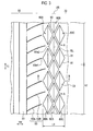
- Fig. 3 is a tread developed view illustrating the area around the recessed shoulder region US according to the first embodiment.
- Fig. 4 is a perspective view illustrating the area around the recessed shoulder region US according to the first embodiment.
- Fig. 5(a) is a cross-sectional view of A-A of Fig. 3
- Fig. 5(b) is a cross-sectional view of B-B of Fig. 3 .
- the recessed shoulder region US is configured of a plurality of recessed portions 80 and a surface portion 90.
- a plurality of recessed portions 80 are formed on the recessed shoulder region US.
- the recessed portion 80 is recessed from the surface of the pneumatic tire 1.
- the ratio of the area occupied by the recessed portions 80 in the recessed shoulder region US is equal to or greater than 60%. For example, when the recessed shoulder region US is 170 to 200 mm 2 , the ratio of the area occupied by the recessed portions 80 in the recessed shoulder region US is 100 to 160 mm 2 (in the first embodiment, 154 mm 2 ).
- the recessed portion 80 is, in the tread width direction TW (in other words, the direction going from the tread 50 to the side walls 60), formed in a plurality (in the figure, three rows). Specifically, the recessed portion 80 is configured of a recessed portion 80A, a recessed portion 80B, and a recessed portion 80C, from the tread 50 to the side wall 60.
- the recessed portion 80A is provided in a position that is substantially the same, in the tire circumference direction TC, as the recessed portion 80C.
- the recessed portion 80B is provided in a position that is shifted by a half-phase, in the tire circumference direction TC, from the recessed portion 80A and the recessed portion 80C.
- An end 80e2 of the recessed portion 80B which is positioned on the innermost side, in the tread width direction TW, is provided in a position that is substantially the same, in the tire circumference direction TC, as the long thin groove 53B, of the width directional thin grooves 53, which is longer in the tread width direction TW than the short thin groove 53A (refer to Fig. 3 and Fig. 4 ).
- a depth D of the recessed portion 80 is set to be 0.5 to 3.0 mm. Specifically, the depth D 80c of the recessed portion 80C formed on the outer side, in the tread width direction TW (by the side wall 60), is less than a depth D 80A of the recessed portion 80A formed on the inner side, in the tread width direction TW (by the tread 50).
- a depth D 80B of the recessed portion 80B positioned between the recessed portion 80A and the recessed portion 80C is preferably greater than the depth D 80A of the recessed portion 80A, while being less than the depth D 80c of the recessed portion 80C.
- the recessed portion 80 is polygonal.
- the recessed portion 80 is quadrilateral, or specifically, rhombic.
- sides 81 in the first embodiment, four sides
- the number of line segments BL in the first embodiment, one
- the number of line segments BL formed on a bottom surface 83 of the recessed portion 80 along the deepest portion 82 of the recessed portion 80 is less than the number of the sides 81 that form the recessed portion 80.
- Line segments BL are formed in a position which is a diagonal of the recessed portion 80 (rhombus) along the tire circumference direction TC.
- the line segments BL are curved in the bottom surface 83 of the recessed portion 80 (refer to Fig. 5(a) ).
- the line segments BL are configured to be 15 to 36 mm.
- the bottom surfaces 83 of the recessed portion 80 are each inclined towards the deepest portion 82 (refer to Fig. 5(b) ).
- the surface portion 90 is a portion where the recessed portions 80 are not formed.
- the surface portion 90 is formed surrounding each of the recessed portions 80. In the surface of the pneumatic tire 1, the surface portion 90 is latticed.
- the width of the recessed shoulder region US indicates, from the end 80e1 of the recessed portion 80A positioned on the innermost side in the tread width direction TW, to an end 80e3 of the recessed portion 80C positioned on the outermost side in the tread width direction TW.
- the recessed portions 80 are not formed.
- the recessed portions 80 and the surface portion 90 are formed. Furthermore, with the pneumatic tires according the examples 1 to 3, the ratios of the area occupied by the recessed portions 80 in the recessed shoulder region US are each different.
- the vehicles fitted with the pneumatic tires 1 according to the examples 1 to 3 when compared to the vehicle fitted with the pneumatic tire according to the comparative example, could exhibit effects in reducing road noise.
- the ratio of the area occupied by the recessed portions 80 in the recessed shoulder region US is equal to or greater than 60%.
- the buttress portion which does not contact the road surface when the road surface is smooth, contacts the road surface when there are small dents and bumps on the road surface, such as a paved road with a rough road surface. Due to these dents and bumps, the buttress portion vibrates, and road noise due to this vibration of the buttress portion is increased.
- a recessed shoulder region US having a predetermined width extends along the tire circumference direction TC, and in the recessed shoulder region US, a plurality of recessed portions 80 and the surface portion 90 are formed.
- the recessed portions 80 do not contact the dents and bumps of the road surface, and the area of the recessed shoulder region US that contacts the road surface is reduced. Due to this, the increase of the contact pressure of the tread 50 is suppressed, and the vibration of the recessed shoulder region US caused by the dents and bumps of the road surface can be suppressed. Accordingly, the generation of road noise due to the vibration of the recessed shoulder region US can be suppressed, and as a result, the pneumatic tire 1 further reducing road noise can be provided.
- the ratio of the area occupied by the recessed portions 80 in the recessed shoulder region US is 100 to 160 mm 2 (in the first embodiment, 154 mm 2 ). Furthermore, when the related ratio is less than 100 mm 2 , there are cases where the dents and bumps of the road surface may contact the recessed portions 80. On the other hand, when the related ratio is more than 160 mm 2 , there are cases where the decrease in shearing rigidity of the recessed shoulder region US cannot be suppressed.
- the relation of V ⁇ L1 ⁇ L2 ⁇ (D/2) is satisfied.
- V is less than L1 ⁇ L2 ⁇ (D/2)
- suppression of the decrease in shearing rigidity of the recessed shoulder region US, and the reduction of the area of the recessed shoulder region US which contacts the road surface, can both be managed. Due to this, while suppressing the generation of road noise, qualities such as controlling stability and cornering performance can be maintained.
- the surface portion 90 is formed surrounding each of the recessed portions 80.
- the recessed portion 80 is polygonal. By this, compared to when the recessed portion 80 is circular or oval-shaped, the recessed portions 80 can be arranged more efficiently in the recessed shoulder region US, further ensuring the suppression of the generation of road noise.
- the sides 81 that form the recessed portion 80 are slanted in relation to the tire circumference direction TC.
- the number of line segments BL formed on the bottom surface 83 of the recessed portion 80 along the deepest portion 82 of the recessed portion 80 is less than the number of the sides 81 that form the recessed portion 80.
- the line segments BL are curved in the bottom surface 83 of the recessed portion 80 (refer to Fig. 5(a) ). Also, the bottom surfaces 83 of the recessed portion 80 are each inclined towards the deepest portion 82 (refer to Fig. 5(b) ).
- the root portion of the surface portion 90 can be reinforced, suppressing the decrease in shearing rigidity of the recessed shoulder region US. Due to this, while suppressing the generation of road noise, qualities such as controlling stability and cornering performance can be maintained.
- the recessed portion 80 is rhombic.
- the line segments BL are formed in a position which is a diagonal of the recessed portion 80 (rhombus) along the tire circumference direction TC.
- the line segments BL along the tire circumference direction TC can be arranged to be longer.
- the recessed portions 80 can be arranged more efficiently in the recessed shoulder region US which is limited in the tire radial direction TR, and suppression of the decrease in shearing rigidity of the recessed shoulder region US, and the reduction of the area of the recessed shoulder region US which contacts the road surface, can both be managed. Due to this, while suppressing the generation of road noise, qualities such as controlling stability and cornering performance can be maintained.
- the surface portion 90 is latticed.
- the sides 81 that form the recessed portion 80 are not in line in the tire circumference direction TC, making it harder for cracks to progress in the tire circumference direction TC, further ensuring the suppression of the progression of cracks.
- the depth D 80c of the recessed portion 80C is less than the depth D 80A of the recessed portion 80A.
- the depth D 80A of the recessed portion 80A is greater than the depth D 80c of the recessed portion 80C.
- the recessed shoulder region US includes the intersection point NP.
- the recessed shoulder region US is provided on the inner side, in the tread width direction TW, and the outer side, in the tread width direction TW, of the intersection point NP.
- the recessed shoulder region US on the inner side when the tire is mounted on the vehicle, is easier to come into contact with the road surface, in a situation where the related negative camber angle is assigned, when compared to the outer side when the tire is mounted on the vehicle.
- the recessed shoulder region US is positioned on the inner side when the tire is mounted on the vehicle.
- the end 80el of the recessed portion 80A is provided in a position that is substantially the same, in the tire circumference direction TC, as the short thin groove 53A.
- the end 80e2 of the recessed portion 80B is provided in a position that is substantially the same, in the tire circumference direction TC, as the long thin groove 53B.
- the relation of ⁇ s ⁇ D is satisfied.
- the suppression of the decrease in shearing rigidity of the recessed shoulder region US, and the reduction of the area of the recessed shoulder region US which contacts the road surface can both be managed. Due to this, while suppressing the generation of road noise, qualities such as controlling stability and cornering performance can be maintained.
- Fig. 6 is a tread developed view illustrating the area around the recessed shoulder region US according to the first modification.
- the recessed portion 80 is rhombic, and the sides 81 that form the recessed portion 80 are slanted in relation to the tire circumference direction TC.
- the recessed portion 180 is not necessarily required to be rectangular, and as illustrated in Fig. 6 , may be triangular, and the shape of the recessed portion 180 may be appropriately varied to correspond to different purposes.
- Fig. 7 is a tread developed view illustrating the area around the recessed shoulder region US according to the second modification.
- the recessed portion 80B is provided in a position shifted, in the tire circumference direction TC, from that of the recessed portion 80A and the recessed portion 80C.
- a recessed portion 280A, a recessed portion 280B, and a recessed portion 280C are provided in such a way that they are lined up in the tire circumference direction TC.
- the surface portion 90 does not necessarily have to be formed surrounding each of the recessed portions 280, and may be provided as a predetermined region between the adjacent recessed portions 280.
- Fig. 8 is a perspective view illustrating the area around the recessed shoulder region US according to the third modification.
- the number of the line segments BL (, which is one) is less than the number of the sides 81 that form the recessed portion 80.
- the number of the line segments BL is equal to the number of the sides 81 that form the recessed portion 380.
- the line segments BL may be curved in the bottom surface 83 of the recessed portion 380, or may be linear.
- the number of line segments BL is not necessarily required to be equal to the number of the sides 81, and may be greater than the number of the sides 81. Also, as illustrated in Fig. 8(b) , the line segments BL do not have to be formed in a position as a diagonal (of the rhombus) along the tire circumference direction TC, and of course may be formed in a position as a diagonal along the tire radial direction TR. In this case, for example, the line segments BL are configured to be 7 to 18 mm.
- the line segments BL are not necessarily required to be provided, and as illustrated in Fig. 9 , may not be provided.
- the bottom surface 83 of the recessed portion 380 is formed by only a curved surface. In this case, when compared to cases where the bottom surfaces 83 of the recessed portion 380 are formed linearly, the stress focusing on the bottom surface 83 is dispersed. For this reason, while suppressing the generation of road noise, the generation of cracks on the bottom surface 83 can also be suppressed.
- Fig. 10(a) is a cross-sectional view in the tread width direction of the pneumatic tire 1A according to the second embodiment.
- Fig. 10(b) is an enlarged view illustrating an area enclosed by the double dot and dash lined area A of Fig. 10(a) .
- the recessed shoulder region US includes the intersection point NP, and has a predetermined width (L1) centered on the intersection point NP.
- the recessed shoulder region US is positioned on the inner side, in the tire radial direction TR, of the intersection point NP.
- the recessed shoulder region US being positioned on the inner side, in the tire radial direction TR, of the intersection point NP, the chances of the recessed shoulder region US (surface portion 90) contacting the dents and bumps of the road surface are lessened, and the suppression of the generation of road noise can be further ensured.
- the embodiments of the present invention may be altered in the following ways.
- the tire although the pneumatic tire 1 filled with air or nitrogen gas is explained, this is not a limitation, and may be a solid tire that is not filled with air or nitrogen gas.
- the configuration of the pneumatic tire 1 is not limited to that explained in the embodiments, and of course may be appropriately configured to correspond to different purposes.
- configurations and the like of the bead portion 10, the carcass 20, the belt 40, and the tread 50 may be appropriately configured to correspond to different purposes.
- the recessed shoulder region US although explained as being positioned on the inner side when the tire is mounted on the vehicle, this is not a limitation, and may be positioned on the outer side, when the tire is mounted on the vehicle, or may be positioned on both the inner and outer sides, when the tire is mounted on the vehicle.
- the straight line L (intersection point NP), although explained as passing over the belt end 41 of the outer side belt layer, this is not a limitation, as long as it passes near the belt end 41.
- the line segments BL although explained as being curved in the bottom surface 83 of the recessed portion 80, this is not a limitation, and may be linear.
- the recessed portion 80 although explained as being formed in a plurality (in three rows) in the direction going from the tread 50 to the side walls 60, this is not a limitation, and appropriately configured to correspond to different purposes.
- the depth D 80c of the recessed portion 80C although explained as being less than the depth D 80A of the recessed portion 80A, this is not a limitation, and may be equal to the depth D 80A of the recessed portion 80A, or may be greater than the depth D 80A of the recessed portion 80A.
- the surface portion 90 although being described as latticed, this is not a limitation, and may be of a shape other than a lattice.
- the present invention can be applied to tires that demand reduction of noise.
Landscapes
- Engineering & Computer Science (AREA)
- Mechanical Engineering (AREA)
- Tires In General (AREA)
Applications Claiming Priority (3)
| Application Number | Priority Date | Filing Date | Title |
|---|---|---|---|
| JP2009200815 | 2009-08-31 | ||
| JP2010006954A JP4709315B2 (ja) | 2009-08-31 | 2010-01-15 | タイヤ |
| PCT/JP2010/051107 WO2011024492A1 (ja) | 2009-08-31 | 2010-01-28 | タイヤ |
Publications (3)
| Publication Number | Publication Date |
|---|---|
| EP2474427A1 EP2474427A1 (en) | 2012-07-11 |
| EP2474427A4 EP2474427A4 (en) | 2013-04-03 |
| EP2474427B1 true EP2474427B1 (en) | 2014-06-04 |
Family
ID=43627606
Family Applications (1)
| Application Number | Title | Priority Date | Filing Date |
|---|---|---|---|
| EP10811545.2A Not-in-force EP2474427B1 (en) | 2009-08-31 | 2010-01-28 | Tire |
Country Status (7)
| Country | Link |
|---|---|
| US (1) | US8783311B2 (da) |
| EP (1) | EP2474427B1 (da) |
| JP (1) | JP4709315B2 (da) |
| KR (1) | KR101165564B1 (da) |
| CN (1) | CN102574426B (da) |
| IN (1) | IN2012DN01915A (da) |
| WO (1) | WO2011024492A1 (da) |
Families Citing this family (14)
| Publication number | Priority date | Publication date | Assignee | Title |
|---|---|---|---|---|
| DE102010017743A1 (de) * | 2010-07-05 | 2012-01-05 | Continental Reifen Deutschland Gmbh | Fahrzeugluftreifen |
| JP5523358B2 (ja) * | 2011-01-05 | 2014-06-18 | 東洋ゴム工業株式会社 | 空気入りタイヤ |
| JP5766537B2 (ja) * | 2011-07-27 | 2015-08-19 | 株式会社ブリヂストン | タイヤ |
| JP5997695B2 (ja) * | 2011-08-04 | 2016-09-28 | 株式会社ブリヂストン | タイヤ |
| JP5695543B2 (ja) * | 2011-10-31 | 2015-04-08 | 住友ゴム工業株式会社 | 空気入りタイヤ |
| JP6068239B2 (ja) * | 2013-04-12 | 2017-01-25 | 株式会社ブリヂストン | 空気入りタイヤ |
| USD776602S1 (en) | 2015-05-08 | 2017-01-17 | Cooper Tire & Rubber Company | Tire tread |
| JP2017024657A (ja) * | 2015-07-27 | 2017-02-02 | 横浜ゴム株式会社 | 空気入りタイヤ |
| JP2017024659A (ja) * | 2015-07-27 | 2017-02-02 | 横浜ゴム株式会社 | 空気入りタイヤ |
| JP2019001277A (ja) * | 2017-06-14 | 2019-01-10 | 株式会社ブリヂストン | タイヤ |
| JP2019104385A (ja) * | 2017-12-12 | 2019-06-27 | 株式会社ブリヂストン | 装飾体 |
| JP7136746B2 (ja) * | 2019-06-11 | 2022-09-13 | 株式会社ブリヂストン | タイヤ |
| JP2024082469A (ja) | 2022-12-08 | 2024-06-20 | Toyo Tire株式会社 | 空気入りタイヤ |
| JP2024082475A (ja) * | 2022-12-08 | 2024-06-20 | Toyo Tire株式会社 | 空気入りタイヤ |
Family Cites Families (18)
| Publication number | Priority date | Publication date | Assignee | Title |
|---|---|---|---|---|
| JPS5340088A (en) * | 1976-09-27 | 1978-04-12 | Toyo Tire & Rubber Co | Production of radial tire |
| JPS6229402A (ja) * | 1985-07-31 | 1987-02-07 | Bridgestone Corp | バイアス構造空気入りタイヤ |
| JPH04238703A (ja) * | 1991-01-10 | 1992-08-26 | Sumitomo Rubber Ind Ltd | 空気入りタイヤ |
| JPH10147113A (ja) * | 1996-11-19 | 1998-06-02 | Bridgestone Corp | 騒音の低い空気入りタイヤ |
| JP4230574B2 (ja) * | 1998-04-24 | 2009-02-25 | 株式会社ブリヂストン | 空気入りタイヤ |
| JP2000016030A (ja) * | 1998-07-07 | 2000-01-18 | Yokohama Rubber Co Ltd:The | 空気入りラジアルタイヤ |
| JP3987209B2 (ja) * | 1998-07-27 | 2007-10-03 | 東洋ゴム工業株式会社 | 空気入りタイヤ |
| JP3391711B2 (ja) * | 1998-09-04 | 2003-03-31 | 住友ゴム工業株式会社 | 重荷重用タイヤ |
| JP2000103206A (ja) * | 1998-09-29 | 2000-04-11 | Bridgestone Corp | 空気入りタイヤ |
| US6164353A (en) | 1999-07-21 | 2000-12-26 | The Yokohama Rubber Co., Ltd. | Pneumatic tire for passenger cars having shoulder recess |
| JP2002205514A (ja) * | 2001-01-05 | 2002-07-23 | Yokohama Rubber Co Ltd:The | 重荷重用空気入りタイヤ |
| JP4474876B2 (ja) * | 2003-09-05 | 2010-06-09 | 横浜ゴム株式会社 | 重荷重用空気入りタイヤ |
| JP4471272B2 (ja) * | 2004-04-23 | 2010-06-02 | 東洋ゴム工業株式会社 | 空気入りタイヤ |
| JP2006117080A (ja) * | 2004-10-21 | 2006-05-11 | Yokohama Rubber Co Ltd:The | 空気入りタイヤ及び空気入りタイヤの設計方法並びに空気入りタイヤの製造方法 |
| JP4736698B2 (ja) * | 2005-10-13 | 2011-07-27 | 横浜ゴム株式会社 | 空気入りタイヤ |
| JP2008024048A (ja) | 2006-07-18 | 2008-02-07 | Bridgestone Corp | 空気入りラジアルタイヤ |
| JP2009200815A (ja) | 2008-02-21 | 2009-09-03 | Nec Corp | 電子機器及びその制御方法 |
| JP2010006954A (ja) | 2008-06-27 | 2010-01-14 | Nof Corp | 電子基板保護用シート |
-
2010
- 2010-01-15 JP JP2010006954A patent/JP4709315B2/ja active Active
- 2010-01-28 CN CN201080038686.3A patent/CN102574426B/zh not_active Expired - Fee Related
- 2010-01-28 IN IN1915DEN2012 patent/IN2012DN01915A/en unknown
- 2010-01-28 WO PCT/JP2010/051107 patent/WO2011024492A1/ja not_active Ceased
- 2010-01-28 EP EP10811545.2A patent/EP2474427B1/en not_active Not-in-force
- 2010-01-28 KR KR1020127004987A patent/KR101165564B1/ko not_active Expired - Fee Related
- 2010-01-28 US US13/393,115 patent/US8783311B2/en not_active Expired - Fee Related
Also Published As
| Publication number | Publication date |
|---|---|
| KR101165564B1 (ko) | 2012-07-16 |
| EP2474427A1 (en) | 2012-07-11 |
| US8783311B2 (en) | 2014-07-22 |
| EP2474427A4 (en) | 2013-04-03 |
| WO2011024492A1 (ja) | 2011-03-03 |
| JP2011068334A (ja) | 2011-04-07 |
| CN102574426A (zh) | 2012-07-11 |
| JP4709315B2 (ja) | 2011-06-22 |
| US20120211135A1 (en) | 2012-08-23 |
| KR20120031310A (ko) | 2012-04-02 |
| CN102574426B (zh) | 2014-08-27 |
| IN2012DN01915A (da) | 2015-07-24 |
Similar Documents
| Publication | Publication Date | Title |
|---|---|---|
| EP2474427B1 (en) | Tire | |
| EP2230102B1 (en) | Pneumatic tire | |
| EP2196329B1 (en) | Pneumatic tire | |
| EP2543522A1 (en) | Two-wheeled automotive vehicle tire | |
| WO2021225146A1 (ja) | タイヤ | |
| JP7701207B2 (ja) | タイヤ | |
| JP7680904B2 (ja) | タイヤ | |
| JP7583258B2 (ja) | タイヤ | |
| JP7633491B2 (ja) | タイヤ | |
| EP3666552B1 (en) | Tyre | |
| US20230173850A1 (en) | Tire | |
| JP4286588B2 (ja) | 空気入りタイヤ | |
| CN118354912A (zh) | 轮胎 | |
| JP7365292B2 (ja) | タイヤ | |
| JP7365290B2 (ja) | タイヤ | |
| JP7365291B2 (ja) | タイヤ | |
| JP7405686B2 (ja) | タイヤ | |
| US12434510B2 (en) | Pneumatic radial tire for passenger vehicles | |
| JP7731278B2 (ja) | 乗用車用空気入りラジアルタイヤ | |
| JP7732879B2 (ja) | 乗用車用空気入りラジアルタイヤ | |
| JP2024098627A (ja) | 空気入りタイヤ | |
| CN117651650A (zh) | 乘用车用充气子午线轮胎 | |
| CN117794750A (zh) | 乘用车用充气子午线轮胎 |
Legal Events
| Date | Code | Title | Description |
|---|---|---|---|
| PUAI | Public reference made under article 153(3) epc to a published international application that has entered the european phase |
Free format text: ORIGINAL CODE: 0009012 |
|
| 17P | Request for examination filed |
Effective date: 20120329 |
|
| AK | Designated contracting states |
Kind code of ref document: A1 Designated state(s): AT BE BG CH CY CZ DE DK EE ES FI FR GB GR HR HU IE IS IT LI LT LU LV MC MK MT NL NO PL PT RO SE SI SK SM TR |
|
| DAX | Request for extension of the european patent (deleted) | ||
| A4 | Supplementary search report drawn up and despatched |
Effective date: 20130305 |
|
| RIC1 | Information provided on ipc code assigned before grant |
Ipc: B60C 11/01 20060101AFI20130227BHEP Ipc: B60C 11/04 20060101ALI20130227BHEP Ipc: B60C 11/13 20060101ALI20130227BHEP Ipc: B60C 5/00 20060101ALI20130227BHEP |
|
| GRAP | Despatch of communication of intention to grant a patent |
Free format text: ORIGINAL CODE: EPIDOSNIGR1 |
|
| INTG | Intention to grant announced |
Effective date: 20131213 |
|
| GRAS | Grant fee paid |
Free format text: ORIGINAL CODE: EPIDOSNIGR3 |
|
| GRAA | (expected) grant |
Free format text: ORIGINAL CODE: 0009210 |
|
| AK | Designated contracting states |
Kind code of ref document: B1 Designated state(s): AT BE BG CH CY CZ DE DK EE ES FI FR GB GR HR HU IE IS IT LI LT LU LV MC MK MT NL NO PL PT RO SE SI SK SM TR |
|
| REG | Reference to a national code |
Ref country code: GB Ref legal event code: FG4D |
|
| REG | Reference to a national code |
Ref country code: CH Ref legal event code: EP |
|
| REG | Reference to a national code |
Ref country code: AT Ref legal event code: REF Ref document number: 670864 Country of ref document: AT Kind code of ref document: T Effective date: 20140615 |
|
| REG | Reference to a national code |
Ref country code: IE Ref legal event code: FG4D |
|
| REG | Reference to a national code |
Ref country code: DE Ref legal event code: R096 Ref document number: 602010016536 Country of ref document: DE Effective date: 20140717 |
|
| REG | Reference to a national code |
Ref country code: AT Ref legal event code: MK05 Ref document number: 670864 Country of ref document: AT Kind code of ref document: T Effective date: 20140604 |
|
| REG | Reference to a national code |
Ref country code: NL Ref legal event code: VDEP Effective date: 20140604 |
|
| PG25 | Lapsed in a contracting state [announced via postgrant information from national office to epo] |
Ref country code: NO Free format text: LAPSE BECAUSE OF FAILURE TO SUBMIT A TRANSLATION OF THE DESCRIPTION OR TO PAY THE FEE WITHIN THE PRESCRIBED TIME-LIMIT Effective date: 20140904 Ref country code: CY Free format text: LAPSE BECAUSE OF FAILURE TO SUBMIT A TRANSLATION OF THE DESCRIPTION OR TO PAY THE FEE WITHIN THE PRESCRIBED TIME-LIMIT Effective date: 20140604 Ref country code: GR Free format text: LAPSE BECAUSE OF FAILURE TO SUBMIT A TRANSLATION OF THE DESCRIPTION OR TO PAY THE FEE WITHIN THE PRESCRIBED TIME-LIMIT Effective date: 20140905 Ref country code: FI Free format text: LAPSE BECAUSE OF FAILURE TO SUBMIT A TRANSLATION OF THE DESCRIPTION OR TO PAY THE FEE WITHIN THE PRESCRIBED TIME-LIMIT Effective date: 20140604 Ref country code: LT Free format text: LAPSE BECAUSE OF FAILURE TO SUBMIT A TRANSLATION OF THE DESCRIPTION OR TO PAY THE FEE WITHIN THE PRESCRIBED TIME-LIMIT Effective date: 20140604 |
|
| REG | Reference to a national code |
Ref country code: LT Ref legal event code: MG4D |
|
| PG25 | Lapsed in a contracting state [announced via postgrant information from national office to epo] |
Ref country code: LV Free format text: LAPSE BECAUSE OF FAILURE TO SUBMIT A TRANSLATION OF THE DESCRIPTION OR TO PAY THE FEE WITHIN THE PRESCRIBED TIME-LIMIT Effective date: 20140604 Ref country code: AT Free format text: LAPSE BECAUSE OF FAILURE TO SUBMIT A TRANSLATION OF THE DESCRIPTION OR TO PAY THE FEE WITHIN THE PRESCRIBED TIME-LIMIT Effective date: 20140604 Ref country code: SE Free format text: LAPSE BECAUSE OF FAILURE TO SUBMIT A TRANSLATION OF THE DESCRIPTION OR TO PAY THE FEE WITHIN THE PRESCRIBED TIME-LIMIT Effective date: 20140604 Ref country code: HR Free format text: LAPSE BECAUSE OF FAILURE TO SUBMIT A TRANSLATION OF THE DESCRIPTION OR TO PAY THE FEE WITHIN THE PRESCRIBED TIME-LIMIT Effective date: 20140604 |
|
| PG25 | Lapsed in a contracting state [announced via postgrant information from national office to epo] |
Ref country code: EE Free format text: LAPSE BECAUSE OF FAILURE TO SUBMIT A TRANSLATION OF THE DESCRIPTION OR TO PAY THE FEE WITHIN THE PRESCRIBED TIME-LIMIT Effective date: 20140604 Ref country code: PT Free format text: LAPSE BECAUSE OF FAILURE TO SUBMIT A TRANSLATION OF THE DESCRIPTION OR TO PAY THE FEE WITHIN THE PRESCRIBED TIME-LIMIT Effective date: 20141006 Ref country code: SK Free format text: LAPSE BECAUSE OF FAILURE TO SUBMIT A TRANSLATION OF THE DESCRIPTION OR TO PAY THE FEE WITHIN THE PRESCRIBED TIME-LIMIT Effective date: 20140604 Ref country code: CZ Free format text: LAPSE BECAUSE OF FAILURE TO SUBMIT A TRANSLATION OF THE DESCRIPTION OR TO PAY THE FEE WITHIN THE PRESCRIBED TIME-LIMIT Effective date: 20140604 Ref country code: RO Free format text: LAPSE BECAUSE OF FAILURE TO SUBMIT A TRANSLATION OF THE DESCRIPTION OR TO PAY THE FEE WITHIN THE PRESCRIBED TIME-LIMIT Effective date: 20140604 Ref country code: ES Free format text: LAPSE BECAUSE OF FAILURE TO SUBMIT A TRANSLATION OF THE DESCRIPTION OR TO PAY THE FEE WITHIN THE PRESCRIBED TIME-LIMIT Effective date: 20140604 |
|
| PG25 | Lapsed in a contracting state [announced via postgrant information from national office to epo] |
Ref country code: NL Free format text: LAPSE BECAUSE OF FAILURE TO SUBMIT A TRANSLATION OF THE DESCRIPTION OR TO PAY THE FEE WITHIN THE PRESCRIBED TIME-LIMIT Effective date: 20140604 Ref country code: PL Free format text: LAPSE BECAUSE OF FAILURE TO SUBMIT A TRANSLATION OF THE DESCRIPTION OR TO PAY THE FEE WITHIN THE PRESCRIBED TIME-LIMIT Effective date: 20140604 Ref country code: IS Free format text: LAPSE BECAUSE OF FAILURE TO SUBMIT A TRANSLATION OF THE DESCRIPTION OR TO PAY THE FEE WITHIN THE PRESCRIBED TIME-LIMIT Effective date: 20141004 |
|
| REG | Reference to a national code |
Ref country code: DE Ref legal event code: R097 Ref document number: 602010016536 Country of ref document: DE |
|
| PLBE | No opposition filed within time limit |
Free format text: ORIGINAL CODE: 0009261 |
|
| STAA | Information on the status of an ep patent application or granted ep patent |
Free format text: STATUS: NO OPPOSITION FILED WITHIN TIME LIMIT |
|
| PG25 | Lapsed in a contracting state [announced via postgrant information from national office to epo] |
Ref country code: DK Free format text: LAPSE BECAUSE OF FAILURE TO SUBMIT A TRANSLATION OF THE DESCRIPTION OR TO PAY THE FEE WITHIN THE PRESCRIBED TIME-LIMIT Effective date: 20140604 |
|
| 26N | No opposition filed |
Effective date: 20150305 |
|
| REG | Reference to a national code |
Ref country code: DE Ref legal event code: R097 Ref document number: 602010016536 Country of ref document: DE Effective date: 20150305 |
|
| PG25 | Lapsed in a contracting state [announced via postgrant information from national office to epo] |
Ref country code: BE Free format text: LAPSE BECAUSE OF FAILURE TO SUBMIT A TRANSLATION OF THE DESCRIPTION OR TO PAY THE FEE WITHIN THE PRESCRIBED TIME-LIMIT Effective date: 20140604 |
|
| PG25 | Lapsed in a contracting state [announced via postgrant information from national office to epo] |
Ref country code: SI Free format text: LAPSE BECAUSE OF FAILURE TO SUBMIT A TRANSLATION OF THE DESCRIPTION OR TO PAY THE FEE WITHIN THE PRESCRIBED TIME-LIMIT Effective date: 20140604 |
|
| REG | Reference to a national code |
Ref country code: CH Ref legal event code: PL |
|
| PG25 | Lapsed in a contracting state [announced via postgrant information from national office to epo] |
Ref country code: LU Free format text: LAPSE BECAUSE OF FAILURE TO SUBMIT A TRANSLATION OF THE DESCRIPTION OR TO PAY THE FEE WITHIN THE PRESCRIBED TIME-LIMIT Effective date: 20150128 |
|
| GBPC | Gb: european patent ceased through non-payment of renewal fee |
Effective date: 20150128 |
|
| PG25 | Lapsed in a contracting state [announced via postgrant information from national office to epo] |
Ref country code: MC Free format text: LAPSE BECAUSE OF FAILURE TO SUBMIT A TRANSLATION OF THE DESCRIPTION OR TO PAY THE FEE WITHIN THE PRESCRIBED TIME-LIMIT Effective date: 20140604 |
|
| PG25 | Lapsed in a contracting state [announced via postgrant information from national office to epo] |
Ref country code: GB Free format text: LAPSE BECAUSE OF NON-PAYMENT OF DUE FEES Effective date: 20150128 Ref country code: LI Free format text: LAPSE BECAUSE OF NON-PAYMENT OF DUE FEES Effective date: 20150131 Ref country code: CH Free format text: LAPSE BECAUSE OF NON-PAYMENT OF DUE FEES Effective date: 20150131 |
|
| REG | Reference to a national code |
Ref country code: IE Ref legal event code: MM4A |
|
| REG | Reference to a national code |
Ref country code: FR Ref legal event code: PLFP Year of fee payment: 7 |
|
| PG25 | Lapsed in a contracting state [announced via postgrant information from national office to epo] |
Ref country code: IE Free format text: LAPSE BECAUSE OF NON-PAYMENT OF DUE FEES Effective date: 20150128 |
|
| PG25 | Lapsed in a contracting state [announced via postgrant information from national office to epo] |
Ref country code: MT Free format text: LAPSE BECAUSE OF FAILURE TO SUBMIT A TRANSLATION OF THE DESCRIPTION OR TO PAY THE FEE WITHIN THE PRESCRIBED TIME-LIMIT Effective date: 20140604 |
|
| REG | Reference to a national code |
Ref country code: FR Ref legal event code: PLFP Year of fee payment: 8 |
|
| PG25 | Lapsed in a contracting state [announced via postgrant information from national office to epo] |
Ref country code: HU Free format text: LAPSE BECAUSE OF FAILURE TO SUBMIT A TRANSLATION OF THE DESCRIPTION OR TO PAY THE FEE WITHIN THE PRESCRIBED TIME-LIMIT; INVALID AB INITIO Effective date: 20100128 Ref country code: SM Free format text: LAPSE BECAUSE OF FAILURE TO SUBMIT A TRANSLATION OF THE DESCRIPTION OR TO PAY THE FEE WITHIN THE PRESCRIBED TIME-LIMIT Effective date: 20140604 Ref country code: BG Free format text: LAPSE BECAUSE OF FAILURE TO SUBMIT A TRANSLATION OF THE DESCRIPTION OR TO PAY THE FEE WITHIN THE PRESCRIBED TIME-LIMIT Effective date: 20140604 |
|
| PG25 | Lapsed in a contracting state [announced via postgrant information from national office to epo] |
Ref country code: TR Free format text: LAPSE BECAUSE OF FAILURE TO SUBMIT A TRANSLATION OF THE DESCRIPTION OR TO PAY THE FEE WITHIN THE PRESCRIBED TIME-LIMIT Effective date: 20140604 |
|
| REG | Reference to a national code |
Ref country code: FR Ref legal event code: PLFP Year of fee payment: 9 |
|
| PG25 | Lapsed in a contracting state [announced via postgrant information from national office to epo] |
Ref country code: MK Free format text: LAPSE BECAUSE OF FAILURE TO SUBMIT A TRANSLATION OF THE DESCRIPTION OR TO PAY THE FEE WITHIN THE PRESCRIBED TIME-LIMIT Effective date: 20140604 |
|
| PGFP | Annual fee paid to national office [announced via postgrant information from national office to epo] |
Ref country code: DE Payment date: 20200121 Year of fee payment: 11 Ref country code: IT Payment date: 20200131 Year of fee payment: 11 |
|
| PGFP | Annual fee paid to national office [announced via postgrant information from national office to epo] |
Ref country code: FR Payment date: 20200121 Year of fee payment: 11 |
|
| REG | Reference to a national code |
Ref country code: DE Ref legal event code: R119 Ref document number: 602010016536 Country of ref document: DE |
|
| PG25 | Lapsed in a contracting state [announced via postgrant information from national office to epo] |
Ref country code: FR Free format text: LAPSE BECAUSE OF NON-PAYMENT OF DUE FEES Effective date: 20210131 |
|
| PG25 | Lapsed in a contracting state [announced via postgrant information from national office to epo] |
Ref country code: DE Free format text: LAPSE BECAUSE OF NON-PAYMENT OF DUE FEES Effective date: 20210803 |
|
| PG25 | Lapsed in a contracting state [announced via postgrant information from national office to epo] |
Ref country code: IT Free format text: LAPSE BECAUSE OF NON-PAYMENT OF DUE FEES Effective date: 20210128 |