EP2473781B1 - Apparatus and method for close coupling of heat recovery steam generators with gas turbines - Google Patents
Apparatus and method for close coupling of heat recovery steam generators with gas turbines Download PDFInfo
- Publication number
- EP2473781B1 EP2473781B1 EP10745054.6A EP10745054A EP2473781B1 EP 2473781 B1 EP2473781 B1 EP 2473781B1 EP 10745054 A EP10745054 A EP 10745054A EP 2473781 B1 EP2473781 B1 EP 2473781B1
- Authority
- EP
- European Patent Office
- Prior art keywords
- tubes
- grate
- exhaust stream
- structural array
- hrsg
- Prior art date
- Legal status (The legal status is an assumption and is not a legal conclusion. Google has not performed a legal analysis and makes no representation as to the accuracy of the status listed.)
- Active
Links
- 238000011084 recovery Methods 0.000 title claims description 8
- 238000000034 method Methods 0.000 title claims description 4
- 230000008878 coupling Effects 0.000 title 1
- 238000010168 coupling process Methods 0.000 title 1
- 238000005859 coupling reaction Methods 0.000 title 1
- 238000011144 upstream manufacturing Methods 0.000 claims description 11
- 238000004891 communication Methods 0.000 claims description 2
- 239000012530 fluid Substances 0.000 claims description 2
- 238000011068 loading method Methods 0.000 description 5
- 238000012546 transfer Methods 0.000 description 3
- 238000009792 diffusion process Methods 0.000 description 2
- 235000010627 Phaseolus vulgaris Nutrition 0.000 description 1
- 244000046052 Phaseolus vulgaris Species 0.000 description 1
- 238000013459 approach Methods 0.000 description 1
- 238000013461 design Methods 0.000 description 1
- 230000003116 impacting effect Effects 0.000 description 1
- 230000001788 irregular Effects 0.000 description 1
- 230000007774 longterm Effects 0.000 description 1
- 238000010248 power generation Methods 0.000 description 1
- 239000007787 solid Substances 0.000 description 1
- 230000008646 thermal stress Effects 0.000 description 1
Images


Classifications
-
- F—MECHANICAL ENGINEERING; LIGHTING; HEATING; WEAPONS; BLASTING
- F22—STEAM GENERATION
- F22B—METHODS OF STEAM GENERATION; STEAM BOILERS
- F22B1/00—Methods of steam generation characterised by form of heating method
- F22B1/02—Methods of steam generation characterised by form of heating method by exploitation of the heat content of hot heat carriers
- F22B1/18—Methods of steam generation characterised by form of heating method by exploitation of the heat content of hot heat carriers the heat carrier being a hot gas, e.g. waste gas such as exhaust gas of internal-combustion engines
- F22B1/1807—Methods of steam generation characterised by form of heating method by exploitation of the heat content of hot heat carriers the heat carrier being a hot gas, e.g. waste gas such as exhaust gas of internal-combustion engines using the exhaust gases of combustion engines
- F22B1/1815—Methods of steam generation characterised by form of heating method by exploitation of the heat content of hot heat carriers the heat carrier being a hot gas, e.g. waste gas such as exhaust gas of internal-combustion engines using the exhaust gases of combustion engines using the exhaust gases of gas-turbines
-
- F—MECHANICAL ENGINEERING; LIGHTING; HEATING; WEAPONS; BLASTING
- F01—MACHINES OR ENGINES IN GENERAL; ENGINE PLANTS IN GENERAL; STEAM ENGINES
- F01D—NON-POSITIVE DISPLACEMENT MACHINES OR ENGINES, e.g. STEAM TURBINES
- F01D25/00—Component parts, details, or accessories, not provided for in, or of interest apart from, other groups
- F01D25/30—Exhaust heads, chambers, or the like
-
- F—MECHANICAL ENGINEERING; LIGHTING; HEATING; WEAPONS; BLASTING
- F02—COMBUSTION ENGINES; HOT-GAS OR COMBUSTION-PRODUCT ENGINE PLANTS
- F02C—GAS-TURBINE PLANTS; AIR INTAKES FOR JET-PROPULSION PLANTS; CONTROLLING FUEL SUPPLY IN AIR-BREATHING JET-PROPULSION PLANTS
- F02C6/00—Plural gas-turbine plants; Combinations of gas-turbine plants with other apparatus; Adaptations of gas-turbine plants for special use
- F02C6/18—Plural gas-turbine plants; Combinations of gas-turbine plants with other apparatus; Adaptations of gas-turbine plants for special use using the waste heat of gas-turbine plants outside the plants themselves, e.g. gas-turbine power heat plants
-
- F—MECHANICAL ENGINEERING; LIGHTING; HEATING; WEAPONS; BLASTING
- F28—HEAT EXCHANGE IN GENERAL
- F28D—HEAT-EXCHANGE APPARATUS, NOT PROVIDED FOR IN ANOTHER SUBCLASS, IN WHICH THE HEAT-EXCHANGE MEDIA DO NOT COME INTO DIRECT CONTACT
- F28D21/00—Heat-exchange apparatus not covered by any of the groups F28D1/00 - F28D20/00
- F28D21/0001—Recuperative heat exchangers
- F28D21/0003—Recuperative heat exchangers the heat being recuperated from exhaust gases
-
- F—MECHANICAL ENGINEERING; LIGHTING; HEATING; WEAPONS; BLASTING
- F28—HEAT EXCHANGE IN GENERAL
- F28D—HEAT-EXCHANGE APPARATUS, NOT PROVIDED FOR IN ANOTHER SUBCLASS, IN WHICH THE HEAT-EXCHANGE MEDIA DO NOT COME INTO DIRECT CONTACT
- F28D7/00—Heat-exchange apparatus having stationary tubular conduit assemblies for both heat-exchange media, the media being in contact with different sides of a conduit wall
- F28D7/16—Heat-exchange apparatus having stationary tubular conduit assemblies for both heat-exchange media, the media being in contact with different sides of a conduit wall the conduits being arranged in parallel spaced relation
- F28D7/1615—Heat-exchange apparatus having stationary tubular conduit assemblies for both heat-exchange media, the media being in contact with different sides of a conduit wall the conduits being arranged in parallel spaced relation the conduits being inside a casing and extending at an angle to the longitudinal axis of the casing; the conduits crossing the conduit for the other heat exchange medium
- F28D7/1623—Heat-exchange apparatus having stationary tubular conduit assemblies for both heat-exchange media, the media being in contact with different sides of a conduit wall the conduits being arranged in parallel spaced relation the conduits being inside a casing and extending at an angle to the longitudinal axis of the casing; the conduits crossing the conduit for the other heat exchange medium with particular pattern of flow of the heat exchange media, e.g. change of flow direction
-
- F—MECHANICAL ENGINEERING; LIGHTING; HEATING; WEAPONS; BLASTING
- F28—HEAT EXCHANGE IN GENERAL
- F28F—DETAILS OF HEAT-EXCHANGE AND HEAT-TRANSFER APPARATUS, OF GENERAL APPLICATION
- F28F19/00—Preventing the formation of deposits or corrosion, e.g. by using filters or scrapers
-
- F—MECHANICAL ENGINEERING; LIGHTING; HEATING; WEAPONS; BLASTING
- F28—HEAT EXCHANGE IN GENERAL
- F28F—DETAILS OF HEAT-EXCHANGE AND HEAT-TRANSFER APPARATUS, OF GENERAL APPLICATION
- F28F9/00—Casings; Header boxes; Auxiliary supports for elements; Auxiliary members within casings
- F28F9/02—Header boxes; End plates
- F28F9/026—Header boxes; End plates with static flow control means, e.g. with means for uniformly distributing heat exchange media into conduits
- F28F9/0263—Header boxes; End plates with static flow control means, e.g. with means for uniformly distributing heat exchange media into conduits by varying the geometry or cross-section of header box
-
- F—MECHANICAL ENGINEERING; LIGHTING; HEATING; WEAPONS; BLASTING
- F28—HEAT EXCHANGE IN GENERAL
- F28F—DETAILS OF HEAT-EXCHANGE AND HEAT-TRANSFER APPARATUS, OF GENERAL APPLICATION
- F28F9/00—Casings; Header boxes; Auxiliary supports for elements; Auxiliary members within casings
- F28F9/02—Header boxes; End plates
- F28F9/026—Header boxes; End plates with static flow control means, e.g. with means for uniformly distributing heat exchange media into conduits
- F28F9/028—Header boxes; End plates with static flow control means, e.g. with means for uniformly distributing heat exchange media into conduits by using inserts for modifying the pattern of flow inside the header box, e.g. by using flow restrictors or permeable bodies or blocks with channels
-
- F—MECHANICAL ENGINEERING; LIGHTING; HEATING; WEAPONS; BLASTING
- F05—INDEXING SCHEMES RELATING TO ENGINES OR PUMPS IN VARIOUS SUBCLASSES OF CLASSES F01-F04
- F05D—INDEXING SCHEME FOR ASPECTS RELATING TO NON-POSITIVE-DISPLACEMENT MACHINES OR ENGINES, GAS-TURBINES OR JET-PROPULSION PLANTS
- F05D2220/00—Application
- F05D2220/30—Application in turbines
- F05D2220/31—Application in turbines in steam turbines
-
- F—MECHANICAL ENGINEERING; LIGHTING; HEATING; WEAPONS; BLASTING
- F28—HEAT EXCHANGE IN GENERAL
- F28F—DETAILS OF HEAT-EXCHANGE AND HEAT-TRANSFER APPARATUS, OF GENERAL APPLICATION
- F28F2265/00—Safety or protection arrangements; Arrangements for preventing malfunction
-
- Y—GENERAL TAGGING OF NEW TECHNOLOGICAL DEVELOPMENTS; GENERAL TAGGING OF CROSS-SECTIONAL TECHNOLOGIES SPANNING OVER SEVERAL SECTIONS OF THE IPC; TECHNICAL SUBJECTS COVERED BY FORMER USPC CROSS-REFERENCE ART COLLECTIONS [XRACs] AND DIGESTS
- Y02—TECHNOLOGIES OR APPLICATIONS FOR MITIGATION OR ADAPTATION AGAINST CLIMATE CHANGE
- Y02E—REDUCTION OF GREENHOUSE GAS [GHG] EMISSIONS, RELATED TO ENERGY GENERATION, TRANSMISSION OR DISTRIBUTION
- Y02E20/00—Combustion technologies with mitigation potential
- Y02E20/16—Combined cycle power plant [CCPP], or combined cycle gas turbine [CCGT]
Definitions
- the present invention relates generally to heat recovery steam generators (HRSGs), and more particularly, to a heat recovery steam generator having a structural array to control the exhaust flow exiting a gas turbine before passing through the heat recovery steam generator.
- HRSGs heat recovery steam generators
- Combined Cycle power plants employ gas turbines with Heat Recovery Steam Generators (HRSGs) that use the thermal energy in the exhaust from gas turbines to generate steam for power generation or process use.
- the large stationary gas turbines used in such power plants may typically have average exhaust gas velocities in the range of 61 m/sec (200ft/sec). The velocity of the gas turbine exhaust is not uniform however and some recent gas turbines have local exhaust gas velocities in the range of 183 m/sec (600 ft/sec).
- HRSGs may have flow areas in the range of 5 to 10 times the gas turbines exit flow area and thus average entering velocities that are 5 to 10 times lower than those exiting the gas turbine. A diverging duct is therefore required to connect the gas turbine to the HRSG.
- FIG. 1 A typical arrangement of the gas turbine exhaust diffuser, connecting duct and HRSG is shown in Figure 1 . It is desirable to locate the HRSG close to the gas turbine in a compact duct arrangement to minimize the area required for the power plant and to minimize the size and cost of the connecting duct. This can result in a high velocity jet of gas impacting the region of the front rows of heat transfer tubes in the HRSG that are in line with the gas turbine exhaust diffuser. Such high velocities can cause flow-induced vibrations that will damage the heat transfer tubes. The high aerodynamic loading on the tube banks can also cause movement of the entire front tube bank resulting in damage to components in and around the tube bank. The non-uniform velocities entering the HRSG front tube rows also reduce the heat transfer effectiveness of these rows. Documents DE 197 37 507 A1 , US 5 532 439 A and US 6 340 002 B1 give examples of HRSG systems with a grate-like structure at a fixed distance upstream of a heat exchanger.
- flow controls have been used in the diverging duct to redirect flow within the duct and improve flow distribution to the front rows of tubes in the HRSG. These flow controls would be subject to very high aerodynamic loadings in a compact duct due to close proximity to the gas turbine. In addition to the steady aerodynamic loading, the flow controls are subject to dynamic loading due to the high levels of turbulence in the duct and thermal stress due to going from ambient temperature to the high gas turbine exhaust temperature. These issues make it unlikely that flow controls located in the diverging duct 36 will survive long-term operation.
- a structural array disposed upstream of the front tubes of an HRSG a distance away from the tubes and employing an attachment structure that allows said distance to be adjusted will overcome such problems, particularly when the turbine and HRSG are closely coupled.
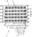
- Fig. 2 is a cross-sectional side elevation view of an HRSG having an inlet duct and a structural array disposed upstream of the tubes of the HRSG in accordance with the present invention.
- Fig. 2 illustrates an HRSG 40 with a structural array 10.
- Fig. 3a is a front view of the HRSG having a structural array secured thereto in accordance to the present invention.
- Fig. 3b is a side elevation view of the structural array of Fig. 3a .
- structural array 10 is disposed upstream of the tube banks 42 of the HRSG 40.
- the structural array 10 is mounted or secured to structural elements or supports 26 at the upstream end of the HRSG 40 to control the flow of the exhaust stream 14 from a turbine (not shown), e.g., a gas turbine.
- a turbine e.g., a gas turbine.
- the structural array 10 extends over the upstream end of the HRSG 40 over a sufficient area to engage or control the exhaust stream 14.
- the structural array 10 comprises a plurality of grate-like panels 18.
- Fig. 4a is a front view of a grate-like panel of the structural array of Fig. 3a .
- Fig. 4b is a side elevation view of the grate-like panel of Fig. 4a .
- Panels 18 are now described with reference to Figures 4a and 4b .
- Panels 18 each have a plurality of horizontal bars 20 connected to a plurality of vertical bars 22.
- the bars 20, 22 may be solid, hollow or generally U-shaped.
- the cross section of each bar may be any geometric shape (i.e., round, oval, square, rectangular, octagonal, etc.) or U-shaped.
- the grid openings 12 may be uniform or irregular.
- the spacing of the vertical and horizontal bars of the array may be uniform or varied.
- the vertical bars 22 of the panel 18 are U-shaped, wherein the orientation of the U-shaped bars are such that the openings of the bars open inwardly towards the center of the panel. While the U-shaped vertical bars 22 are shown in such an orientation, the invention contemplates that the U-shaped bars may be disposed in any orientation.
- Each of the panels 18 are mounted or secured (e.g., welded, bolted, or other means of attachment) to horizontal supports 24, which are in turn attach or secured to structural supports 26 of the HRSG 40.
- the mounting of the panels 18 to the structural supports 26 and not the tubes 46 of the HRSG reduce fatigue on the tubes.
- the horizontal supports 24 are formed of a pair of vertically disposed tubes 30 are welded together.
- the present invention contemplates that the horizontal supports 24 may be formed from any support bean.
- the exhaust stream 14 from the gas turbine flows through the connecting duct 34 and HRSG inlet duct 36.
- the high velocity flow passes through the grate-like structural array 10, wherein the exhaust stream 14 is diffused and further distributed across the tubes 46 of the HRSG 40.
- the structural array 10 is constructed of structural components 20, 22, 24 to withstand the forces imparted by the high velocity exhaust stream 14. Pined and/or slip connections are used where appropriate to allow for thermal expansion.
- the size and spacing of the components 20, 22, 24 is arranged to provide sufficient resistance to redirect part of the high velocity exhaust stream 14 to the sections of the front row tubes 48 that would have had little or no gas flow, improving the distribution of gas flow into the HRSG 40.
- the structural components 20, 22, 24 are also sized and spaced such that the remaining flow passing though the array 10 is distributed through grid openings 12 into a large number of smaller jets.
- the smaller jets start with a diameter D the same as the grid openings 12. These are on the order of 1/10 of the distance from the structural array 10 to the tubes 46. This allows the small multiple jets to partially dissipate before reaching the tubes 46 and lowers the loading on the region of the tubes that would have been subjected to unacceptable velocities without the structural array 10.
- the extent of the front row of tubes 46 that are protected by the structural array 10 and the diameter of the grid openings 12 will be based on physical flow modeling of the specific gas turbine and HRSG 40.
- structural array 10 is on adjustable mounts (50 of Figure 2 ) such that the distance from the structural array and tubes 46 may be adjusted. This allows for adjustment of more or less dissipation of the exhaust jets as they impinge upon the tubes 46. Since more diffusion of the exhaust stream 14 result in higher exhaust back pressure, the system can be interactively optimized for both backpressure and diffusion.
Landscapes
- Engineering & Computer Science (AREA)
- Mechanical Engineering (AREA)
- General Engineering & Computer Science (AREA)
- Physics & Mathematics (AREA)
- Thermal Sciences (AREA)
- Chemical & Material Sciences (AREA)
- Combustion & Propulsion (AREA)
- Life Sciences & Earth Sciences (AREA)
- Sustainable Development (AREA)
- Sustainable Energy (AREA)
- Geometry (AREA)
- Heat-Exchange Devices With Radiators And Conduit Assemblies (AREA)
- Engine Equipment That Uses Special Cycles (AREA)
Applications Claiming Priority (3)
| Application Number | Priority Date | Filing Date | Title |
|---|---|---|---|
| US23960409P | 2009-09-03 | 2009-09-03 | |
| US12/850,108 US10001272B2 (en) | 2009-09-03 | 2010-08-04 | Apparatus and method for close coupling of heat recovery steam generators with gas turbines |
| PCT/US2010/044496 WO2011028356A2 (en) | 2009-09-03 | 2010-08-05 | Apparatus and method for close coupling of heat recovery steam generators with gas turbines |
Publications (2)
| Publication Number | Publication Date |
|---|---|
| EP2473781A2 EP2473781A2 (en) | 2012-07-11 |
| EP2473781B1 true EP2473781B1 (en) | 2021-05-26 |
Family
ID=43622825
Family Applications (1)
| Application Number | Title | Priority Date | Filing Date |
|---|---|---|---|
| EP10745054.6A Active EP2473781B1 (en) | 2009-09-03 | 2010-08-05 | Apparatus and method for close coupling of heat recovery steam generators with gas turbines |
Country Status (10)
| Country | Link |
|---|---|
| US (1) | US10001272B2 (ru) |
| EP (1) | EP2473781B1 (ru) |
| KR (3) | KR101850236B1 (ru) |
| CN (1) | CN102498343B (ru) |
| CA (1) | CA2773092C (ru) |
| IL (1) | IL218389A (ru) |
| IN (1) | IN2012DN02834A (ru) |
| MX (1) | MX2012002554A (ru) |
| RU (1) | RU2620309C2 (ru) |
| WO (1) | WO2011028356A2 (ru) |
Families Citing this family (73)
| Publication number | Priority date | Publication date | Assignee | Title |
|---|---|---|---|---|
| EP2276559A4 (en) | 2008-03-28 | 2017-10-18 | Exxonmobil Upstream Research Company | Low emission power generation and hydrocarbon recovery systems and methods |
| CA2715186C (en) | 2008-03-28 | 2016-09-06 | Exxonmobil Upstream Research Company | Low emission power generation and hydrocarbon recovery systems and methods |
| AU2009303735B2 (en) | 2008-10-14 | 2014-06-26 | Exxonmobil Upstream Research Company | Methods and systems for controlling the products of combustion |
| SG10201402156TA (en) | 2009-06-05 | 2014-10-30 | Exxonmobil Upstream Res Co | Combustor systems and methods for using same |
| AU2010318595C1 (en) | 2009-11-12 | 2016-10-06 | Exxonmobil Upstream Research Company | Low emission power generation and hydrocarbon recovery systems and methods |
| ES2620775T3 (es) * | 2009-11-19 | 2017-06-29 | Nem Power-Systems, Niederlassung Deutschland Der Nem B.V. Niederlande | Disposición para influenciar un flujo de gas de escape |
| CA2801492C (en) | 2010-07-02 | 2017-09-26 | Exxonmobil Upstream Research Company | Stoichiometric combustion with exhaust gas recirculation and direct contact cooler |
| TWI593878B (zh) | 2010-07-02 | 2017-08-01 | 艾克頌美孚上游研究公司 | 用於控制燃料燃燒之系統及方法 |
| CN102959203B (zh) | 2010-07-02 | 2018-10-09 | 埃克森美孚上游研究公司 | 通过排气再循环的浓缩空气的化学计量燃烧 |
| WO2012003080A1 (en) | 2010-07-02 | 2012-01-05 | Exxonmobil Upstream Research Company | Low emission power generation systems and methods |
| WO2012003077A1 (en) | 2010-07-02 | 2012-01-05 | Exxonmobil Upstream Research Company | Low emission triple-cycle power generation systems and methods |
| US9903279B2 (en) | 2010-08-06 | 2018-02-27 | Exxonmobil Upstream Research Company | Systems and methods for optimizing stoichiometric combustion |
| WO2012018458A1 (en) | 2010-08-06 | 2012-02-09 | Exxonmobil Upstream Research Company | System and method for exhaust gas extraction |
| TWI593872B (zh) | 2011-03-22 | 2017-08-01 | 艾克頌美孚上游研究公司 | 整合系統及產生動力之方法 |
| TWI563166B (en) | 2011-03-22 | 2016-12-21 | Exxonmobil Upstream Res Co | Integrated generation systems and methods for generating power |
| TWI563165B (en) | 2011-03-22 | 2016-12-21 | Exxonmobil Upstream Res Co | Power generation system and method for generating power |
| TWI564474B (zh) | 2011-03-22 | 2017-01-01 | 艾克頌美孚上游研究公司 | 於渦輪系統中控制化學計量燃燒的整合系統和使用彼之產生動力的方法 |
| US9810050B2 (en) | 2011-12-20 | 2017-11-07 | Exxonmobil Upstream Research Company | Enhanced coal-bed methane production |
| US9353682B2 (en) | 2012-04-12 | 2016-05-31 | General Electric Company | Methods, systems and apparatus relating to combustion turbine power plants with exhaust gas recirculation |
| US9784185B2 (en) | 2012-04-26 | 2017-10-10 | General Electric Company | System and method for cooling a gas turbine with an exhaust gas provided by the gas turbine |
| US10273880B2 (en) | 2012-04-26 | 2019-04-30 | General Electric Company | System and method of recirculating exhaust gas for use in a plurality of flow paths in a gas turbine engine |
| US9803865B2 (en) | 2012-12-28 | 2017-10-31 | General Electric Company | System and method for a turbine combustor |
| US9869279B2 (en) | 2012-11-02 | 2018-01-16 | General Electric Company | System and method for a multi-wall turbine combustor |
| US10107495B2 (en) | 2012-11-02 | 2018-10-23 | General Electric Company | Gas turbine combustor control system for stoichiometric combustion in the presence of a diluent |
| US9599070B2 (en) | 2012-11-02 | 2017-03-21 | General Electric Company | System and method for oxidant compression in a stoichiometric exhaust gas recirculation gas turbine system |
| US9611756B2 (en) | 2012-11-02 | 2017-04-04 | General Electric Company | System and method for protecting components in a gas turbine engine with exhaust gas recirculation |
| US9574496B2 (en) | 2012-12-28 | 2017-02-21 | General Electric Company | System and method for a turbine combustor |
| US10215412B2 (en) | 2012-11-02 | 2019-02-26 | General Electric Company | System and method for load control with diffusion combustion in a stoichiometric exhaust gas recirculation gas turbine system |
| US9631815B2 (en) | 2012-12-28 | 2017-04-25 | General Electric Company | System and method for a turbine combustor |
| US9708977B2 (en) | 2012-12-28 | 2017-07-18 | General Electric Company | System and method for reheat in gas turbine with exhaust gas recirculation |
| US10100741B2 (en) | 2012-11-02 | 2018-10-16 | General Electric Company | System and method for diffusion combustion with oxidant-diluent mixing in a stoichiometric exhaust gas recirculation gas turbine system |
| US10208677B2 (en) | 2012-12-31 | 2019-02-19 | General Electric Company | Gas turbine load control system |
| US9581081B2 (en) | 2013-01-13 | 2017-02-28 | General Electric Company | System and method for protecting components in a gas turbine engine with exhaust gas recirculation |
| US9512759B2 (en) | 2013-02-06 | 2016-12-06 | General Electric Company | System and method for catalyst heat utilization for gas turbine with exhaust gas recirculation |
| US9938861B2 (en) | 2013-02-21 | 2018-04-10 | Exxonmobil Upstream Research Company | Fuel combusting method |
| TW201502356A (zh) | 2013-02-21 | 2015-01-16 | Exxonmobil Upstream Res Co | 氣渦輪機排氣中氧之減少 |
| US10221762B2 (en) | 2013-02-28 | 2019-03-05 | General Electric Company | System and method for a turbine combustor |
| TW201500635A (zh) | 2013-03-08 | 2015-01-01 | Exxonmobil Upstream Res Co | 處理廢氣以供用於提高油回收 |
| US20140250945A1 (en) | 2013-03-08 | 2014-09-11 | Richard A. Huntington | Carbon Dioxide Recovery |
| EP2964735A1 (en) | 2013-03-08 | 2016-01-13 | Exxonmobil Upstream Research Company | Power generation and methane recovery from methane hydrates |
| US9618261B2 (en) | 2013-03-08 | 2017-04-11 | Exxonmobil Upstream Research Company | Power generation and LNG production |
| JP6484845B2 (ja) * | 2013-06-25 | 2019-03-20 | 三菱重工コンプレッサ株式会社 | ガスタービンコンバインドサイクル設備、水上設備 |
| US9631542B2 (en) | 2013-06-28 | 2017-04-25 | General Electric Company | System and method for exhausting combustion gases from gas turbine engines |
| US9617914B2 (en) | 2013-06-28 | 2017-04-11 | General Electric Company | Systems and methods for monitoring gas turbine systems having exhaust gas recirculation |
| US9835089B2 (en) | 2013-06-28 | 2017-12-05 | General Electric Company | System and method for a fuel nozzle |
| TWI654368B (zh) | 2013-06-28 | 2019-03-21 | 美商艾克頌美孚上游研究公司 | 用於控制在廢氣再循環氣渦輪機系統中的廢氣流之系統、方法與媒體 |
| US9903588B2 (en) | 2013-07-30 | 2018-02-27 | General Electric Company | System and method for barrier in passage of combustor of gas turbine engine with exhaust gas recirculation |
| US9587510B2 (en) | 2013-07-30 | 2017-03-07 | General Electric Company | System and method for a gas turbine engine sensor |
| US9951658B2 (en) | 2013-07-31 | 2018-04-24 | General Electric Company | System and method for an oxidant heating system |
| US10145626B2 (en) | 2013-11-15 | 2018-12-04 | General Electric Technology Gmbh | Internally stiffened extended service heat recovery steam generator apparatus |
| US10030588B2 (en) | 2013-12-04 | 2018-07-24 | General Electric Company | Gas turbine combustor diagnostic system and method |
| US9752458B2 (en) | 2013-12-04 | 2017-09-05 | General Electric Company | System and method for a gas turbine engine |
| US10227920B2 (en) | 2014-01-15 | 2019-03-12 | General Electric Company | Gas turbine oxidant separation system |
| US9863267B2 (en) | 2014-01-21 | 2018-01-09 | General Electric Company | System and method of control for a gas turbine engine |
| US9915200B2 (en) | 2014-01-21 | 2018-03-13 | General Electric Company | System and method for controlling the combustion process in a gas turbine operating with exhaust gas recirculation |
| US10079564B2 (en) | 2014-01-27 | 2018-09-18 | General Electric Company | System and method for a stoichiometric exhaust gas recirculation gas turbine system |
| US10047633B2 (en) | 2014-05-16 | 2018-08-14 | General Electric Company | Bearing housing |
| US10655542B2 (en) | 2014-06-30 | 2020-05-19 | General Electric Company | Method and system for startup of gas turbine system drive trains with exhaust gas recirculation |
| US9885290B2 (en) | 2014-06-30 | 2018-02-06 | General Electric Company | Erosion suppression system and method in an exhaust gas recirculation gas turbine system |
| US10060359B2 (en) | 2014-06-30 | 2018-08-28 | General Electric Company | Method and system for combustion control for gas turbine system with exhaust gas recirculation |
| US9819292B2 (en) | 2014-12-31 | 2017-11-14 | General Electric Company | Systems and methods to respond to grid overfrequency events for a stoichiometric exhaust recirculation gas turbine |
| US9869247B2 (en) | 2014-12-31 | 2018-01-16 | General Electric Company | Systems and methods of estimating a combustion equivalence ratio in a gas turbine with exhaust gas recirculation |
| US10788212B2 (en) | 2015-01-12 | 2020-09-29 | General Electric Company | System and method for an oxidant passageway in a gas turbine system with exhaust gas recirculation |
| US10094566B2 (en) | 2015-02-04 | 2018-10-09 | General Electric Company | Systems and methods for high volumetric oxidant flow in gas turbine engine with exhaust gas recirculation |
| US10316746B2 (en) | 2015-02-04 | 2019-06-11 | General Electric Company | Turbine system with exhaust gas recirculation, separation and extraction |
| US10253690B2 (en) | 2015-02-04 | 2019-04-09 | General Electric Company | Turbine system with exhaust gas recirculation, separation and extraction |
| US10267270B2 (en) | 2015-02-06 | 2019-04-23 | General Electric Company | Systems and methods for carbon black production with a gas turbine engine having exhaust gas recirculation |
| US10145269B2 (en) | 2015-03-04 | 2018-12-04 | General Electric Company | System and method for cooling discharge flow |
| US10480792B2 (en) | 2015-03-06 | 2019-11-19 | General Electric Company | Fuel staging in a gas turbine engine |
| EP3457071B1 (en) * | 2017-09-18 | 2023-05-17 | Valeo Autosystemy SP. Z.O.O. | A protection device for a heat exchanger |
| US11209157B2 (en) | 2018-07-27 | 2021-12-28 | The Clever-Brooks Company, Inc. | Modular heat recovery steam generator system for rapid installation |
| US10907821B2 (en) * | 2019-03-07 | 2021-02-02 | General Electric Company | HRSG with stepped tube restraints |
| US11519597B2 (en) * | 2019-11-08 | 2022-12-06 | General Electric Company | Multiple cooled supports for heat exchange tubes in heat exchanger |
Citations (3)
| Publication number | Priority date | Publication date | Assignee | Title |
|---|---|---|---|---|
| US5532439A (en) * | 1994-06-23 | 1996-07-02 | Transco Products Inc. | Silencer assembly with acoustical modules therein |
| DE19737507A1 (de) * | 1997-08-28 | 1999-03-11 | Dampers Engineering Gmbh | Anordnung zur Beeinflussung des Dralls eines Abgasstroms |
| US6340002B1 (en) * | 1999-12-09 | 2002-01-22 | Alstom (Switzerland) Ltd | Heat-recovery steam generator |
Family Cites Families (18)
| Publication number | Priority date | Publication date | Assignee | Title |
|---|---|---|---|---|
| US2968147A (en) * | 1957-04-23 | 1961-01-17 | Boeing Co | Supersonic diffuser with shock positioning means |
| US3442324A (en) * | 1967-03-06 | 1969-05-06 | American Mach & Foundry | Heat recovery device for turbine gases |
| DE3206626A1 (de) * | 1982-02-24 | 1983-09-01 | Kraftwerk Union AG, 4330 Mülheim | Abgaskanal fuer gasturbinen |
| US4427058A (en) * | 1982-12-13 | 1984-01-24 | General Electric Company | HRSG Sidewall baffle |
| RU2018047C1 (ru) | 1989-09-05 | 1994-08-15 | Акционерное общество "Белгородский завод энергетического машиностроения" | Котел-утилизатор |
| US5431009A (en) * | 1993-12-21 | 1995-07-11 | Combustion Engineering, Inc. | Heat recovery steam generator inlet duct |
| JP3512487B2 (ja) | 1994-10-24 | 2004-03-29 | 株式会社東芝 | 排熱回収ボイラ |
| US5555718A (en) | 1994-11-10 | 1996-09-17 | Combustion Engineering, Inc. | Method and apparatus for injecting reactant for catalytic reduction in a gas turbine combined cycle system |
| IT1290579B1 (it) | 1997-03-07 | 1998-12-10 | Abb Combustion Engineering S P | Caldaia a recupero, munita di condotto divergente. |
| US5946901A (en) * | 1997-12-17 | 1999-09-07 | Combustion Engineering, Inc. | Method and apparatus for improving gas flow in heat recovery steam generators |
| DE10017987C1 (de) * | 2000-04-11 | 2001-11-22 | Nem Power Systems Niederlassun | Verfahren und Anordnung zur Beaufschlagung eines Abhitzekessels mit dem Abgas einer Gasturbine |
| US6453852B1 (en) * | 2000-05-22 | 2002-09-24 | Corn Company, Inc. | Temperature stratified superheater and duct burner |
| US20030115817A1 (en) * | 2000-06-22 | 2003-06-26 | New Horizons Shutters, Inc. | Reinforced window shutter |
| US6851514B2 (en) * | 2002-04-15 | 2005-02-08 | Air Handling Engineering Ltd. | Outlet silencer and heat recovery structures for gas turbine |
| CN100472131C (zh) * | 2003-07-30 | 2009-03-25 | 巴布考克日立株式会社 | 模块单元及构造排热回收锅炉的方法 |
| US7963097B2 (en) * | 2008-01-07 | 2011-06-21 | Alstom Technology Ltd | Flexible assembly of recuperator for combustion turbine exhaust |
| US20100064655A1 (en) * | 2008-09-16 | 2010-03-18 | General Electric Company | System and method for managing turbine exhaust gas temperature |
| ES2620775T3 (es) * | 2009-11-19 | 2017-06-29 | Nem Power-Systems, Niederlassung Deutschland Der Nem B.V. Niederlande | Disposición para influenciar un flujo de gas de escape |
-
2010
- 2010-08-04 US US12/850,108 patent/US10001272B2/en active Active
- 2010-08-05 KR KR1020167030883A patent/KR101850236B1/ko active IP Right Grant
- 2010-08-05 EP EP10745054.6A patent/EP2473781B1/en active Active
- 2010-08-05 WO PCT/US2010/044496 patent/WO2011028356A2/en active Application Filing
- 2010-08-05 RU RU2012112807A patent/RU2620309C2/ru not_active IP Right Cessation
- 2010-08-05 CA CA2773092A patent/CA2773092C/en not_active Expired - Fee Related
- 2010-08-05 CN CN201080040389.2A patent/CN102498343B/zh not_active Expired - Fee Related
- 2010-08-05 KR KR1020127008258A patent/KR20120058598A/ko not_active Application Discontinuation
- 2010-08-05 MX MX2012002554A patent/MX2012002554A/es active IP Right Grant
- 2010-08-05 KR KR1020157019607A patent/KR20150091180A/ko active Application Filing
- 2010-08-05 IN IN2834DEN2012 patent/IN2012DN02834A/en unknown
-
2012
- 2012-02-29 IL IL218389A patent/IL218389A/en not_active IP Right Cessation
Patent Citations (3)
| Publication number | Priority date | Publication date | Assignee | Title |
|---|---|---|---|---|
| US5532439A (en) * | 1994-06-23 | 1996-07-02 | Transco Products Inc. | Silencer assembly with acoustical modules therein |
| DE19737507A1 (de) * | 1997-08-28 | 1999-03-11 | Dampers Engineering Gmbh | Anordnung zur Beeinflussung des Dralls eines Abgasstroms |
| US6340002B1 (en) * | 1999-12-09 | 2002-01-22 | Alstom (Switzerland) Ltd | Heat-recovery steam generator |
Also Published As
| Publication number | Publication date |
|---|---|
| WO2011028356A3 (en) | 2011-07-21 |
| CN102498343A (zh) | 2012-06-13 |
| KR101850236B1 (ko) | 2018-04-18 |
| MX2012002554A (es) | 2012-06-01 |
| IN2012DN02834A (ru) | 2015-07-24 |
| AU2010289954B2 (en) | 2016-02-11 |
| EP2473781A2 (en) | 2012-07-11 |
| RU2620309C2 (ru) | 2017-05-24 |
| CA2773092A1 (en) | 2011-03-10 |
| KR20160130534A (ko) | 2016-11-11 |
| US20110048010A1 (en) | 2011-03-03 |
| US10001272B2 (en) | 2018-06-19 |
| KR20120058598A (ko) | 2012-06-07 |
| RU2012112807A (ru) | 2013-10-10 |
| IL218389A0 (en) | 2012-04-30 |
| IL218389A (en) | 2017-05-29 |
| CN102498343B (zh) | 2018-10-26 |
| AU2010289954A8 (en) | 2016-02-25 |
| WO2011028356A2 (en) | 2011-03-10 |
| AU2010289954A1 (en) | 2012-03-29 |
| KR20150091180A (ko) | 2015-08-07 |
| CA2773092C (en) | 2017-07-25 |
Similar Documents
| Publication | Publication Date | Title |
|---|---|---|
| EP2473781B1 (en) | Apparatus and method for close coupling of heat recovery steam generators with gas turbines | |
| KR101367484B1 (ko) | 증기발생기 | |
| US7168251B1 (en) | Wind energy turbine | |
| US7100356B2 (en) | Heat recovery apparatus with aerodynamic diffusers | |
| EP2429690B1 (en) | Natural draft air cooled steam condenser | |
| US20100276129A1 (en) | Indirect dry cooling tower apparatus and method | |
| US5431009A (en) | Heat recovery steam generator inlet duct | |
| US20130008163A1 (en) | Tubular solar receivers and systems using the same | |
| US20160376986A1 (en) | Dual Purpose Heat Transfer Surface Device | |
| AU2010289954B9 (en) | Apparatus and method for close coupling of heat recovery steam generators with gas turbines | |
| AU2010289954B8 (en) | Apparatus and method for close coupling of heat recovery steam generators with gas turbines | |
| EP2981770B1 (en) | Concentrating central solar receiver | |
| KR101469124B1 (ko) | 곡관부를 구비한 열회수장치 | |
| RU2476802C2 (ru) | Радиатор отопления из тепловой трубы | |
| EP4321801B1 (en) | Exhaust gas flow regulator and heat recovery steam generator having same | |
| CA2129158A1 (en) | Steam generator | |
| EP4083502A1 (en) | Heat recovery steam generator and thermal steam generation plant | |
| JPH07167571A (ja) | 発電プラントの復水器 | |
| EP2878885B1 (en) | Internally stiffened extended service heat recovery steam generator apparatus | |
| US4380085A (en) | Angled gas conduit | |
| JPH08233212A (ja) | 熱交換器 | |
| TH73519B (th) | เครื่องมือและวิธีการสำหรับการต่อประกบปิดของเครื่องกำเนิดไอน้ำแบบนำความร้อนกลับมาใช้ซึ่งมีกังหันแก๊ส | |
| JP2014031908A (ja) | 排熱回収ボイラのダクト | |
| JPH06272847A (ja) | ガスダクト装置 |
Legal Events
| Date | Code | Title | Description |
|---|---|---|---|
| PUAI | Public reference made under article 153(3) epc to a published international application that has entered the european phase |
Free format text: ORIGINAL CODE: 0009012 |
|
| 17P | Request for examination filed |
Effective date: 20120228 |
|
| AK | Designated contracting states |
Kind code of ref document: A2 Designated state(s): AL AT BE BG CH CY CZ DE DK EE ES FI FR GB GR HR HU IE IS IT LI LT LU LV MC MK MT NL NO PL PT RO SE SI SK SM TR |
|
| DAX | Request for extension of the european patent (deleted) | ||
| 17Q | First examination report despatched |
Effective date: 20151104 |
|
| RAP1 | Party data changed (applicant data changed or rights of an application transferred) |
Owner name: GENERAL ELECTRIC TECHNOLOGY GMBH |
|
| STAA | Information on the status of an ep patent application or granted ep patent |
Free format text: STATUS: EXAMINATION IS IN PROGRESS |
|
| STAA | Information on the status of an ep patent application or granted ep patent |
Free format text: STATUS: EXAMINATION IS IN PROGRESS |
|
| GRAP | Despatch of communication of intention to grant a patent |
Free format text: ORIGINAL CODE: EPIDOSNIGR1 |
|
| STAA | Information on the status of an ep patent application or granted ep patent |
Free format text: STATUS: GRANT OF PATENT IS INTENDED |
|
| INTG | Intention to grant announced |
Effective date: 20210210 |
|
| GRAS | Grant fee paid |
Free format text: ORIGINAL CODE: EPIDOSNIGR3 |
|
| GRAA | (expected) grant |
Free format text: ORIGINAL CODE: 0009210 |
|
| STAA | Information on the status of an ep patent application or granted ep patent |
Free format text: STATUS: THE PATENT HAS BEEN GRANTED |
|
| RAP3 | Party data changed (applicant data changed or rights of an application transferred) |
Owner name: GENERAL ELECTRIC TECHNOLOGY GMBH |
|
| AK | Designated contracting states |
Kind code of ref document: B1 Designated state(s): AL AT BE BG CH CY CZ DE DK EE ES FI FR GB GR HR HU IE IS IT LI LT LU LV MC MK MT NL NO PL PT RO SE SI SK SM TR |
|
| REG | Reference to a national code |
Ref country code: GB Ref legal event code: FG4D |
|
| REG | Reference to a national code |
Ref country code: CH Ref legal event code: EP |
|
| REG | Reference to a national code |
Ref country code: DE Ref legal event code: R096 Ref document number: 602010067041 Country of ref document: DE |
|
| REG | Reference to a national code |
Ref country code: AT Ref legal event code: REF Ref document number: 1396592 Country of ref document: AT Kind code of ref document: T Effective date: 20210615 |
|
| REG | Reference to a national code |
Ref country code: IE Ref legal event code: FG4D |
|
| REG | Reference to a national code |
Ref country code: LT Ref legal event code: MG9D |
|
| REG | Reference to a national code |
Ref country code: AT Ref legal event code: MK05 Ref document number: 1396592 Country of ref document: AT Kind code of ref document: T Effective date: 20210526 |
|
| PG25 | Lapsed in a contracting state [announced via postgrant information from national office to epo] |
Ref country code: AT Free format text: LAPSE BECAUSE OF FAILURE TO SUBMIT A TRANSLATION OF THE DESCRIPTION OR TO PAY THE FEE WITHIN THE PRESCRIBED TIME-LIMIT Effective date: 20210526 Ref country code: BG Free format text: LAPSE BECAUSE OF FAILURE TO SUBMIT A TRANSLATION OF THE DESCRIPTION OR TO PAY THE FEE WITHIN THE PRESCRIBED TIME-LIMIT Effective date: 20210826 Ref country code: HR Free format text: LAPSE BECAUSE OF FAILURE TO SUBMIT A TRANSLATION OF THE DESCRIPTION OR TO PAY THE FEE WITHIN THE PRESCRIBED TIME-LIMIT Effective date: 20210526 Ref country code: FI Free format text: LAPSE BECAUSE OF FAILURE TO SUBMIT A TRANSLATION OF THE DESCRIPTION OR TO PAY THE FEE WITHIN THE PRESCRIBED TIME-LIMIT Effective date: 20210526 Ref country code: LT Free format text: LAPSE BECAUSE OF FAILURE TO SUBMIT A TRANSLATION OF THE DESCRIPTION OR TO PAY THE FEE WITHIN THE PRESCRIBED TIME-LIMIT Effective date: 20210526 |
|
| REG | Reference to a national code |
Ref country code: NL Ref legal event code: MP Effective date: 20210526 |
|
| PG25 | Lapsed in a contracting state [announced via postgrant information from national office to epo] |
Ref country code: NO Free format text: LAPSE BECAUSE OF FAILURE TO SUBMIT A TRANSLATION OF THE DESCRIPTION OR TO PAY THE FEE WITHIN THE PRESCRIBED TIME-LIMIT Effective date: 20210826 Ref country code: PL Free format text: LAPSE BECAUSE OF FAILURE TO SUBMIT A TRANSLATION OF THE DESCRIPTION OR TO PAY THE FEE WITHIN THE PRESCRIBED TIME-LIMIT Effective date: 20210526 Ref country code: PT Free format text: LAPSE BECAUSE OF FAILURE TO SUBMIT A TRANSLATION OF THE DESCRIPTION OR TO PAY THE FEE WITHIN THE PRESCRIBED TIME-LIMIT Effective date: 20210927 Ref country code: GR Free format text: LAPSE BECAUSE OF FAILURE TO SUBMIT A TRANSLATION OF THE DESCRIPTION OR TO PAY THE FEE WITHIN THE PRESCRIBED TIME-LIMIT Effective date: 20210827 Ref country code: IS Free format text: LAPSE BECAUSE OF FAILURE TO SUBMIT A TRANSLATION OF THE DESCRIPTION OR TO PAY THE FEE WITHIN THE PRESCRIBED TIME-LIMIT Effective date: 20210926 Ref country code: LV Free format text: LAPSE BECAUSE OF FAILURE TO SUBMIT A TRANSLATION OF THE DESCRIPTION OR TO PAY THE FEE WITHIN THE PRESCRIBED TIME-LIMIT Effective date: 20210526 Ref country code: SE Free format text: LAPSE BECAUSE OF FAILURE TO SUBMIT A TRANSLATION OF THE DESCRIPTION OR TO PAY THE FEE WITHIN THE PRESCRIBED TIME-LIMIT Effective date: 20210526 |
|
| PG25 | Lapsed in a contracting state [announced via postgrant information from national office to epo] |
Ref country code: NL Free format text: LAPSE BECAUSE OF FAILURE TO SUBMIT A TRANSLATION OF THE DESCRIPTION OR TO PAY THE FEE WITHIN THE PRESCRIBED TIME-LIMIT Effective date: 20210526 |
|
| PG25 | Lapsed in a contracting state [announced via postgrant information from national office to epo] |
Ref country code: ES Free format text: LAPSE BECAUSE OF FAILURE TO SUBMIT A TRANSLATION OF THE DESCRIPTION OR TO PAY THE FEE WITHIN THE PRESCRIBED TIME-LIMIT Effective date: 20210526 Ref country code: RO Free format text: LAPSE BECAUSE OF FAILURE TO SUBMIT A TRANSLATION OF THE DESCRIPTION OR TO PAY THE FEE WITHIN THE PRESCRIBED TIME-LIMIT Effective date: 20210526 Ref country code: SM Free format text: LAPSE BECAUSE OF FAILURE TO SUBMIT A TRANSLATION OF THE DESCRIPTION OR TO PAY THE FEE WITHIN THE PRESCRIBED TIME-LIMIT Effective date: 20210526 Ref country code: SK Free format text: LAPSE BECAUSE OF FAILURE TO SUBMIT A TRANSLATION OF THE DESCRIPTION OR TO PAY THE FEE WITHIN THE PRESCRIBED TIME-LIMIT Effective date: 20210526 Ref country code: DK Free format text: LAPSE BECAUSE OF FAILURE TO SUBMIT A TRANSLATION OF THE DESCRIPTION OR TO PAY THE FEE WITHIN THE PRESCRIBED TIME-LIMIT Effective date: 20210526 Ref country code: CZ Free format text: LAPSE BECAUSE OF FAILURE TO SUBMIT A TRANSLATION OF THE DESCRIPTION OR TO PAY THE FEE WITHIN THE PRESCRIBED TIME-LIMIT Effective date: 20210526 Ref country code: EE Free format text: LAPSE BECAUSE OF FAILURE TO SUBMIT A TRANSLATION OF THE DESCRIPTION OR TO PAY THE FEE WITHIN THE PRESCRIBED TIME-LIMIT Effective date: 20210526 |
|
| REG | Reference to a national code |
Ref country code: DE Ref legal event code: R097 Ref document number: 602010067041 Country of ref document: DE |
|
| REG | Reference to a national code |
Ref country code: CH Ref legal event code: PL |
|
| PLBE | No opposition filed within time limit |
Free format text: ORIGINAL CODE: 0009261 |
|
| STAA | Information on the status of an ep patent application or granted ep patent |
Free format text: STATUS: NO OPPOSITION FILED WITHIN TIME LIMIT |
|
| PG25 | Lapsed in a contracting state [announced via postgrant information from national office to epo] |
Ref country code: MC Free format text: LAPSE BECAUSE OF FAILURE TO SUBMIT A TRANSLATION OF THE DESCRIPTION OR TO PAY THE FEE WITHIN THE PRESCRIBED TIME-LIMIT Effective date: 20210526 |
|
| GBPC | Gb: european patent ceased through non-payment of renewal fee |
Effective date: 20210826 |
|
| PG25 | Lapsed in a contracting state [announced via postgrant information from national office to epo] |
Ref country code: LI Free format text: LAPSE BECAUSE OF NON-PAYMENT OF DUE FEES Effective date: 20210831 Ref country code: CH Free format text: LAPSE BECAUSE OF NON-PAYMENT OF DUE FEES Effective date: 20210831 |
|
| 26N | No opposition filed |
Effective date: 20220301 |
|
| PG25 | Lapsed in a contracting state [announced via postgrant information from national office to epo] |
Ref country code: IS Free format text: LAPSE BECAUSE OF FAILURE TO SUBMIT A TRANSLATION OF THE DESCRIPTION OR TO PAY THE FEE WITHIN THE PRESCRIBED TIME-LIMIT Effective date: 20210926 Ref country code: LU Free format text: LAPSE BECAUSE OF NON-PAYMENT OF DUE FEES Effective date: 20210805 Ref country code: AL Free format text: LAPSE BECAUSE OF FAILURE TO SUBMIT A TRANSLATION OF THE DESCRIPTION OR TO PAY THE FEE WITHIN THE PRESCRIBED TIME-LIMIT Effective date: 20210526 |
|
| PG25 | Lapsed in a contracting state [announced via postgrant information from national office to epo] |
Ref country code: IT Free format text: LAPSE BECAUSE OF FAILURE TO SUBMIT A TRANSLATION OF THE DESCRIPTION OR TO PAY THE FEE WITHIN THE PRESCRIBED TIME-LIMIT Effective date: 20210526 Ref country code: IE Free format text: LAPSE BECAUSE OF NON-PAYMENT OF DUE FEES Effective date: 20210805 Ref country code: GB Free format text: LAPSE BECAUSE OF NON-PAYMENT OF DUE FEES Effective date: 20210826 Ref country code: FR Free format text: LAPSE BECAUSE OF NON-PAYMENT OF DUE FEES Effective date: 20210831 |
|
| PG25 | Lapsed in a contracting state [announced via postgrant information from national office to epo] |
Ref country code: HU Free format text: LAPSE BECAUSE OF FAILURE TO SUBMIT A TRANSLATION OF THE DESCRIPTION OR TO PAY THE FEE WITHIN THE PRESCRIBED TIME-LIMIT; INVALID AB INITIO Effective date: 20100805 Ref country code: CY Free format text: LAPSE BECAUSE OF FAILURE TO SUBMIT A TRANSLATION OF THE DESCRIPTION OR TO PAY THE FEE WITHIN THE PRESCRIBED TIME-LIMIT Effective date: 20210526 |
|
| P01 | Opt-out of the competence of the unified patent court (upc) registered |
Effective date: 20230522 |
|
| PGFP | Annual fee paid to national office [announced via postgrant information from national office to epo] |
Ref country code: DE Payment date: 20230720 Year of fee payment: 14 Ref country code: BE Payment date: 20230720 Year of fee payment: 14 |
|
| PG25 | Lapsed in a contracting state [announced via postgrant information from national office to epo] |
Ref country code: MK Free format text: LAPSE BECAUSE OF FAILURE TO SUBMIT A TRANSLATION OF THE DESCRIPTION OR TO PAY THE FEE WITHIN THE PRESCRIBED TIME-LIMIT Effective date: 20210526 |
|
| PG25 | Lapsed in a contracting state [announced via postgrant information from national office to epo] |
Ref country code: TR Free format text: LAPSE BECAUSE OF FAILURE TO SUBMIT A TRANSLATION OF THE DESCRIPTION OR TO PAY THE FEE WITHIN THE PRESCRIBED TIME-LIMIT Effective date: 20210526 |