EP2473393B1 - Carrosserie de véhicule à ensemble pont arrière modulaire - Google Patents
Carrosserie de véhicule à ensemble pont arrière modulaire Download PDFInfo
- Publication number
- EP2473393B1 EP2473393B1 EP10740652.2A EP10740652A EP2473393B1 EP 2473393 B1 EP2473393 B1 EP 2473393B1 EP 10740652 A EP10740652 A EP 10740652A EP 2473393 B1 EP2473393 B1 EP 2473393B1
- Authority
- EP
- European Patent Office
- Prior art keywords
- axle
- bodywork
- link
- receiving
- damper
- Prior art date
- Legal status (The legal status is an assumption and is not a legal conclusion. Google has not performed a legal analysis and makes no representation as to the accuracy of the status listed.)
- Not-in-force
Links
Images


Classifications
-
- B—PERFORMING OPERATIONS; TRANSPORTING
- B62—LAND VEHICLES FOR TRAVELLING OTHERWISE THAN ON RAILS
- B62D—MOTOR VEHICLES; TRAILERS
- B62D21/00—Understructures, i.e. chassis frame on which a vehicle body may be mounted
- B62D21/11—Understructures, i.e. chassis frame on which a vehicle body may be mounted with resilient means for suspension, e.g. of wheels or engine; sub-frames for mounting engine or suspensions
Definitions
- the invention relates to a body of a motor vehicle with longitudinal members and a rear axle connected to the body, the Schuachskonstrutation has means for securing the Schuachskonstrutation to the body and a suspension, and the Schuachskonstrutation is formed as a twist beam axle or multi-link axle.
- Twist-beam axles and multi-link axles are typical embodiments of rear axle constructions of a motor vehicle. Both rear axle designs meet different requirements.
- the torsion beam axle provides a cost-effective suspension, which is used primarily in the mid and small car area. It has a small space requirement, a small mass connected to the wheel and favorable translations between the wheel and spring dampers.
- the wheel carriers are attached to flexurally and torsionally stiff trailing arms, which are firmly connected to each other via a cross member.
- the cross member is rigid and simultaneously designed torsionally soft, so that a limited, independent compression of both wheels is possible.
- Twisted-beam axles are not suitable for providing a simultaneous drive concept on the rear axle, since the cross member, but also the side members, of the torsion beam axle usually stand in the way of necessary drive shafts.
- the rear axle construction is based on multi-link axles resorted to, on the one hand can realize higher comfort requirements and on the other hand, enough space between the rear wheels for the drive ready.
- different handlebars control the lane and the fall of the rear wheel during the Radhubes.
- Multi-link axles usually have an auxiliary frame, which is constructed of cross members and longitudinal members and which is bolted to the vehicle body.
- the connections of the torsion beam axle and the multi-link axle are usually different, so that for each axle type different rear areas for the vehicle bodies must be made. This requires that the bodyshell of the body must be controlled in such a way before installing the Schuachskonstrutation so that different rear areas are provided in the body for the different axle types.
- the present invention seeks to provide a generic body of a motor vehicle with Schuachskonstrutation available, which in a cost effective manner a modular Schuachschte, d. H. the optional use of a torsion beam axle or a multi-link axle, allows.
- the object shown for a generic body of a motor vehicle is achieved in that the side members comprises means for receiving the fasteners and the suspension of a torsion beam and a multi-link axle, via the means for receiving the suspension, both the suspension of a Twist-beam axle and a multi-link axle is receivable, and wherein in the longitudinal member of the body strut-pot or spring-damper pot for receiving the suspension of Schuachskonstrutation are provided.
- the body has means for receiving the fastening means of the rear axle construction, which can be used by the composite link and the multi-link axle.
- the body side receiving means for the attachment of thrust plates which are provided for stabilizing the subframe of a multi-link axle
- the body means for receiving the fasteners of a torsion beam axis, which for receiving fasteners are usable by shear plates, the Stabilization of the subframe of a multi-link axle are provided.
- a simplified attachment of the torsion beam axle to the body can be ensured according to a next embodiment in that the longitudinal members of the torsion beam axle are connected via a vertical mounting to the body.
- the corresponding receiving means of the body are then in fact also suitable in a simple manner for receiving the fastening means of the thrust plates.
- the body for attachment of the multi-link axle at least one console attached to the rear side member of the body.
- This console can consist of several attachments. Although it leads to a slightly increased weight of the body during installation of the torsion-beam axle, this weight increase is comparatively low in comparison with the concept known from the prior art.
- the console is a particularly simple provision of connection points for a multi-link axle, so that overall the cost of this body variant are particularly low due to the uncontrolled shell.
- the suspension of the Deutschenachskonstrutation on at least two struts with integrated damper element or at least two spring elements with separate damper elements is more cost-effective overall.
- a particularly simple recording of the suspension is inventively provided by the fact that in the longitudinal member of the body strut-pot or spring-damper pot for receiving the suspension of the rear axle are provided.
- the spring-damper-receiving pot preferably have between the receptacle of the strut and the damper strut on a depth jump to improve the stability of the damper pot, which consists of a deep-drawn half-shell.
- the damper element is arranged in front of the axle center of the respective rear wheel and / or the spring element behind the axle center of the respective rear wheel.
- the torsion beam axle and / or the multi-link axle has a recessed mounting for the damper elements.
- the recessed mounting of the damper elements ensures in particular a maximum damper path to allow the most comfortable suspension. Also for the recessed mounting of the damper improved possibilities arise at arranged before the axle center damper element. However, the desired ground clearance for the vehicle must be observed.
- Fig. 1 now shows a perspective view of an embodiment of a body according to the invention 1 of a motor vehicle.
- longitudinal members 2, 3 are provided, which have means for receiving the fastening means of a composite link and a multi-link axle 4, 5, 6, 7, 8, 9.
- the means for receiving the fasteners of a composite link and a multi-link axle, for example, as in the illustrated embodiment by Verschraubungspole 4, 5 may be formed in the side rails 2, 3, which are used as a connection point for the twist beam axis or as attachment points for shear plates.
- means for receiving the multi-link axle are provided on the longitudinal members 2, 3 in the form of a bracket 6, 7, 8 and 9.
- the multi-link axle in Fig. 1 not shown, uses the connection points 6a, 7a, 8a, 9a for fixing the subframe of the multi-link axle.
- the inventive embodiment of a vehicle body 1 receiving means for receiving the suspension of the composite link and multi-link axle which are inserted as a spring-damper receiving pots 10, 11 in the side rail. There they form a kind of partition plate, which leads to a significant stiffening of the longitudinal member 2, 3 in this area.
- the bracket 6, 7, 8, 9 of the vehicle body 1 remains on the vehicle body 1, even when a torsion beam axle 12 is mounted, which does not require the connection points provided by the console.
- the torsion beam axle uses only the means 4, 5 for receiving the fasteners of the torsion beam axle and the spring-damper receiving cups 10, 11 for connection.
- the additional weight which is accepted by the provision of the console in the vehicle body 1, and the additional cost of the vehicle body 1 due to the console provided but disproportionate to the cost reduction due to the enabled uncontrolled shell of the body 1, which by the provision of the console 6, 7, 8, 9 is achieved in a simple manner.
- Not controlled means that the shell of the body 1 to assembly of the rear axle 12, 22 does not have to be divided into two ways, one for a body 1 with multi-link 22 and another for a body 1 with twist beam axis 12.
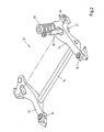
- Fig. 2 shows in a perspective view adapted to the vehicle body 1 rear axle construction in the form of a torsion beam axle 12.
- the longitudinal beams 13, 14 of the torsion beam axle are interconnected via a cross member 15.
- the longitudinal members 13, 14 of the torsion beam axle 12 are fastened via a vertical mounting 16, 17 to the vehicle body 1 and to its longitudinal member 2, 3.
- the damper 18 is disposed in front of the axle center 19 of the respective rear wheel and the spring element 20 behind the axle center. Together with the recessed bearing 21 of the damper element 18 is optimized in terms of the driving dynamics and Schuachskinematik Twist-beam axle 12 provided.
- the recessed bearing of the damper element 18 additionally ensures a sufficient damper path for increased comfort.
- Fig. 3 shows a perspective view of a likewise adapted to the vehicle body 1 rear axle construction in the form of a multi-link axle 22.
- the multi-link axle 22 consists of two cross members 23, 24, which are interconnected by two longitudinal members 25, 26 and form the subframe for the multi-link axle.
- the thrust plates 27, 28, for example, in the vehicle body 1 on the side members 2, 3 are fixed, where in the case of installation of a torsion beam axis 12, the horizontal mounting of the torsion beam axle.
- the subframe formed by the longitudinal and transverse beams 23, 24, 25, 26 uses the connection points 6a, 7a, 8a and 9a of the vehicle body 1 via their attachment points 29, 30, 31, 32.
- the multi-link also uses receiving means, which by the Vehicle body 1 for the twist-beam axle 12 are provided.
- the damper element 33 is disposed in front of the axle center 35 of the rear wheel.
- the spring element 34 is finally disposed behind the axle center 35, so that an optimized Schuachskinematik is achieved.
- Both spring and damper elements 33, 34 use for connection to the vehicle body 1, the combined spring-damper-receiving pots 10, 11 of in Fig. 1 illustrated embodiment of a vehicle body 1.
- the bearing of the damper element 33 is recessed relative to the mounting of the spring element 34 in order to keep the damper path correspondingly large.
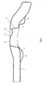
- Fig. 4 now shows in a sectional view of the structure of the rear side member 2 of the vehicle body Fig. 1 , On the one hand, the side member 2, which is formed continuously from the center to the rear of the vehicle, can be seen.
- the receiving points 7a and 9a serve to secure the console in the points 30 and 31.
- the recessed in the longitudinal member 2 spring-damper pot 11 has a portion 11b, which is provided for receiving the damper element 18, 33.
- the spring element 20, 34 of the torsion beam axle 12 or the multi-link axle 22 is received in the region 11 a of the spring-damper receiving pot 11.
- a step 11 c which serves to stiffen the structure of the pot 11.
- the spring-damper pot 11 is like a bulkhead inserted into the side rail 2, so that a stiffening effect is achieved by the pot 11 in the side rail 2.
- the embodiment of the vehicle body 1 according to the invention with the associated axle structures 12, 22 shows that it is possible to provide a vehicle body, which provides a modular rear axle construction with little effort, so that a not controlled shell of the body can be achieved. This reduces the cost of providing additional variants to drives and rear axle designs of a motor vehicle.
Landscapes
- Engineering & Computer Science (AREA)
- Chemical & Material Sciences (AREA)
- Combustion & Propulsion (AREA)
- Transportation (AREA)
- Mechanical Engineering (AREA)
- Vehicle Body Suspensions (AREA)
Claims (9)
- Carrosserie (1) d'un véhicule avec des longerons (2, 3) et une construction d'essieu arrière (12, 22) reliée à la carrosserie, dans laquelle la construction d'essieu arrière comporte des moyens (16, 17, 27, 28, 29, 30, 31, 32) pour fixer la construction d'essieu arrière (12, 22) à la carrosserie (1) et une suspension (18, 20, 33, 34) et la construction d'essieu arrière est constituée comme essieu semi-rigide (12) ou comme essieu multibras (22),
caractérisée en ce que les longerons (2, 3) comportent des moyens (4, 5, 6, 7, 8, 9, 10, 11) destinés à loger des moyens de fixation et la supension (18, 20, 33, 34) d'un essieu semi-rigide (12) ou multibras (22), tant la suspension (18, 20, 33, 34) d'un essieu semi-rigide (12) que d'un essieu multibras (22) pouvant être logée par les moyens destinés à loger la suspension (18, 20, 33, 34) et pots de logement de jambe de suspension ou pots de logement de combiné ressort-amortisseur (10, 11) étant prévues dans le longeron (2, 3) de la carrosserie pour loger la suspension (18, 20, 33, 34) de la construction d'essieu arrière (12, 22). - Carrosserie selon la revendication 1 caractérisée en ce que la carrosserie comporte des moyens (4, 5) destinés à loger des moyens de fixation de la construction d'essieu arrière qui peuvent être utilisés par l'essieu semi-rigide (12) et l'essieu multibras (22).
- Carrosserie selon la revendication 1 ou 2 caractérisée en ce que la carrosserie comporte des moyens (4, 5) destinés à loger des moyens de fixation d'un essieu semi-rigide qui peuvent être utilisés pour loger des moyens de fixation de tôles coulissantes (27, 28) qui sont prévues pour stabiliser le cadre auxiliaire (23, 24, 25, 26) d'un essieu multibras (22).
- Carrosserie selon l'une quelconque des revendications 1 à 3 caractérisée en ce que les longerons (13, 14) de l'essieu semi-rigide sont reliés à la carrosserie par un logement vertical (16, 17).
- Carrosserie selon l'une quelconque des revendications 1 à 4 caractérisée en ce que la carrosserie (1) comporte au moins une console (6, 7, 8, 9) fixée au longeron arrière de la carrosserie pour fixer l'essieu multibras (22).
- Carrosserie selon l'une quelconque des revendications 1 à 5 caractérisée en ce que la suspension de la construction d'essieu arrière (12, 22) comporte au moins deux jambes de suspension avec élément amortiseur intégré ou au moins deux éléments de suspension (20, 34) avec éléments amortisseurs (18, 33) séparés.
- Carrosserie selon l'une quelconque des revendications 1 à 6 caractérisée en ce que l'élément amortisseur (18, 33) séparé est disposé en face de l'élément de suspension (20, 34) en direction de l'avant du véhicule.
- Carrosserie selon l'une quelconque des revendications 1 à 7 caractérisée en ce que l'élément amortisseur (18, 33) est disposé avant le centre d'essieu (19, 35) de la roue arrière correspondante et/ou l'élément de suspension (20, 34) est disposé derrière le centre d'essieu de la roue arrière correspondante (19, 35).
- Carrosserie selon l'une quelconque des revendications 1 à 8 caractérisée en ce que l'essieu semi-rigide (12) et/ou l'essieu multibras (22) comporte un logement creusé (21) pour les éléments amortisseurs (18, 33).
Applications Claiming Priority (2)
| Application Number | Priority Date | Filing Date | Title |
|---|---|---|---|
| DE102009043913A DE102009043913A1 (de) | 2009-08-31 | 2009-08-31 | Fahrzeugkarosserie mit modularer Hinterachskonstruktion |
| PCT/EP2010/061508 WO2011023523A1 (fr) | 2009-08-31 | 2010-08-06 | Carrosserie de véhicule à ensemble pont arrière modulaire |
Publications (2)
| Publication Number | Publication Date |
|---|---|
| EP2473393A1 EP2473393A1 (fr) | 2012-07-11 |
| EP2473393B1 true EP2473393B1 (fr) | 2015-02-11 |
Family
ID=42990298
Family Applications (1)
| Application Number | Title | Priority Date | Filing Date |
|---|---|---|---|
| EP10740652.2A Not-in-force EP2473393B1 (fr) | 2009-08-31 | 2010-08-06 | Carrosserie de véhicule à ensemble pont arrière modulaire |
Country Status (5)
| Country | Link |
|---|---|
| US (1) | US8925947B2 (fr) |
| EP (1) | EP2473393B1 (fr) |
| CN (1) | CN102695642A (fr) |
| DE (1) | DE102009043913A1 (fr) |
| WO (1) | WO2011023523A1 (fr) |
Families Citing this family (6)
| Publication number | Priority date | Publication date | Assignee | Title |
|---|---|---|---|---|
| DE102012013784A1 (de) | 2012-07-11 | 2014-01-16 | GM Global Technology Operations, LLC (n.d. Ges. d. Staates Delaware) | Kraftfahrzeugkarosserie mit einem außenliegenden Verstärkungselement für die Hinterachsanbindung |
| DE102013013325A1 (de) * | 2013-08-09 | 2015-02-12 | Audi Ag | Hilfsrahmen für ein Kraftfahrzeug |
| DE102014202095A1 (de) | 2014-02-05 | 2015-08-06 | Volkswagen Aktiengesellschaft | Verbundlenkerachse |
| DE102016220786B4 (de) * | 2016-10-24 | 2024-03-28 | Ford Global Technologies, Llc | Hinterradaufhängung für Kraftfahrzeuge |
| DE102019200214A1 (de) * | 2019-01-10 | 2020-07-16 | Zf Friedrichshafen Ag | Lenkbare Verbundlenkerachse für ein Kraftfahrzeug, Längslenker und Kraftfahrzeug |
| CN115158462B (zh) * | 2022-06-28 | 2024-05-10 | 一汽奔腾轿车有限公司 | 一种汽车后纵梁总成 |
Family Cites Families (15)
| Publication number | Priority date | Publication date | Assignee | Title |
|---|---|---|---|---|
| US4256292A (en) * | 1978-11-29 | 1981-03-17 | General Motors Corporation | Jounce bumper for suspensions |
| US4941677A (en) | 1987-08-10 | 1990-07-17 | Honda Giken Kogyo Kabushiki Kaisha | Independent wheel suspension system |
| DE19708421A1 (de) * | 1997-03-01 | 1998-09-03 | Opel Adam Ag | Hilfsrahmen für die Vorder- oder Hinterradaufhängung eines Kraftfahrzeuges |
| DE19730404B4 (de) * | 1997-07-16 | 2005-04-21 | Daimlerchrysler Ag | Hilfsrahmen für Kraftfahrzeuge |
| DE20009689U1 (de) * | 2000-05-31 | 2001-10-11 | Benteler Werke Ag | Verbundlenkerhinterachse |
| CZ296802B6 (cs) * | 2000-05-31 | 2006-06-14 | Benteler Ag | Kliková náprava s prícnou torzní tycí |
| JP3866176B2 (ja) * | 2002-09-18 | 2007-01-10 | 本田技研工業株式会社 | 車体構造 |
| US6755429B1 (en) * | 2003-05-06 | 2004-06-29 | Ford Global Technologies, Llc | Independent suspension for rear wheels of automotive vehicle |
| CN100457481C (zh) * | 2003-12-06 | 2009-02-04 | 现代自动车株式会社 | 多联杆后悬架系统 |
| KR100579258B1 (ko) * | 2003-12-30 | 2006-05-11 | 현대자동차주식회사 | 후륜 서스펜션 장치 |
| DE102004032808B4 (de) * | 2004-07-07 | 2010-03-18 | GM Global Technology Operations, Inc., Detroit | Kraftfahrzeughinterachskonstruktion mit einer Verbundlenkerhinterachse und einem zusätzlichen Fahrschemel, sowie Verbundlenkerhinterachse wie auch Fahrschemel hierfür |
| DE102006001060A1 (de) * | 2006-01-07 | 2008-01-24 | GM Global Technology Operations, Inc., Detroit | Vorrichtung zur Aufhängung eines Hinterrades eines Kraftfahrzeuges |
| JP2008183956A (ja) * | 2007-01-29 | 2008-08-14 | Mazda Motor Corp | 車両用駆動装置の配設構造 |
| DE102007043121A1 (de) * | 2007-09-10 | 2009-03-12 | GM Global Technology Operations, Inc., Detroit | Verbundlenkerachse mit elastisch aufgehängtem Radträger |
| KR100925959B1 (ko) | 2008-08-06 | 2009-11-09 | 현대자동차주식회사 | 차량의 리어 차체구조 |
-
2009
- 2009-08-31 DE DE102009043913A patent/DE102009043913A1/de not_active Ceased
-
2010
- 2010-08-06 EP EP10740652.2A patent/EP2473393B1/fr not_active Not-in-force
- 2010-08-06 WO PCT/EP2010/061508 patent/WO2011023523A1/fr active Application Filing
- 2010-08-06 CN CN2010800386079A patent/CN102695642A/zh active Pending
-
2012
- 2012-02-27 US US13/405,880 patent/US8925947B2/en not_active Expired - Fee Related
Also Published As
| Publication number | Publication date |
|---|---|
| US8925947B2 (en) | 2015-01-06 |
| DE102009043913A1 (de) | 2011-03-10 |
| CN102695642A (zh) | 2012-09-26 |
| US20120211962A1 (en) | 2012-08-23 |
| WO2011023523A1 (fr) | 2011-03-03 |
| EP2473393A1 (fr) | 2012-07-11 |
Similar Documents
| Publication | Publication Date | Title |
|---|---|---|
| EP2823976B1 (fr) | Faux-châssis pour un véhicule automobile | |
| DE19536460B4 (de) | Teilrahmen für ein Fahrzeug | |
| EP2473393B1 (fr) | Carrosserie de véhicule à ensemble pont arrière modulaire | |
| DE19812701B4 (de) | Karosseriestruktur für den Frontbereich eines Kraftfahrzeuges | |
| DE102014205632A1 (de) | Einzelradaufhängung sowie Hinterachse mit Einzelradaufhängungen für ein Fahrzeug und entsprechend ausgestattetes Fahrzeug | |
| EP2663463B1 (fr) | Montage d'une transmission d'essieu à l'arrière d'une voiture particulière | |
| DE102009042060A1 (de) | Strukturbauteil für Hinterrahmenstruktur eines Kraftfahrzeugs | |
| DE102006013547B4 (de) | Hilfsrahmen für Kraftfahrzeuge sowie ein Verfahren zur Montage von Antriebsaggregaten von Kraftfahrzeugen auf solchen Hilfsrahmen | |
| DE102008045008A1 (de) | Modularer Multifunktionslagerbock | |
| DE102014205635A1 (de) | Einzelradaufhängung sowie Hinterachse mit Einzelradaufhängungen für ein Fahrzeug und entsprechend ausgestattetes Fahrzeug | |
| DE10036396B4 (de) | Fahrschemel-Modul für ein Kraftfahrzeug | |
| DE102010061154A1 (de) | Aktive Verbundlenkerachse | |
| WO2004048181A1 (fr) | Structure avant de vehicule automobile | |
| DE102007027783A1 (de) | Fahrzeug | |
| EP1655164B1 (fr) | Véhicule transformé en quatre roues motrices | |
| DE202014101432U1 (de) | Einzelradaufhängung sowie Hinterachse mit Einzelradaufhängungen für ein Fahrzeug und entsprechend ausgestattetes Fahrzeug | |
| AT501922B1 (de) | Nutzfahrzeug, insbesondere lastkraftwagen, mit spezieller aufhängung und lenkung zweier benachbarter vorderachsen | |
| DE102016206649A1 (de) | Hilfsrahmen für ein Fahrzeug | |
| DE19537573C2 (de) | Allrad-Kfz | |
| DE102008045082A1 (de) | Hinterachse eines Kraftfahrzeugs mit Hinterradantrieb | |
| DE19849474B4 (de) | Aufhängung einer Hinterachse eines Kraftfahrzeuges | |
| DE102013112466A1 (de) | Fahrschemel für ein Kraftfahrzeug | |
| WO2005066010A1 (fr) | Chassis de vehicule a moteur | |
| EP0940322A1 (fr) | Chassis pour véhicule utilitaire lourd | |
| DE10108034B4 (de) | Auf Fahrzeuge bezogene Verbesserungen |
Legal Events
| Date | Code | Title | Description |
|---|---|---|---|
| PUAI | Public reference made under article 153(3) epc to a published international application that has entered the european phase |
Free format text: ORIGINAL CODE: 0009012 |
|
| 17P | Request for examination filed |
Effective date: 20120131 |
|
| AK | Designated contracting states |
Kind code of ref document: A1 Designated state(s): AL AT BE BG CH CY CZ DE DK EE ES FI FR GB GR HR HU IE IS IT LI LT LU LV MC MK MT NL NO PL PT RO SE SI SK SM TR |
|
| DAX | Request for extension of the european patent (deleted) | ||
| GRAP | Despatch of communication of intention to grant a patent |
Free format text: ORIGINAL CODE: EPIDOSNIGR1 |
|
| INTG | Intention to grant announced |
Effective date: 20140916 |
|
| GRAS | Grant fee paid |
Free format text: ORIGINAL CODE: EPIDOSNIGR3 |
|
| GRAA | (expected) grant |
Free format text: ORIGINAL CODE: 0009210 |
|
| AK | Designated contracting states |
Kind code of ref document: B1 Designated state(s): AL AT BE BG CH CY CZ DE DK EE ES FI FR GB GR HR HU IE IS IT LI LT LU LV MC MK MT NL NO PL PT RO SE SI SK SM TR |
|
| REG | Reference to a national code |
Ref country code: GB Ref legal event code: FG4D Free format text: NOT ENGLISH |
|
| REG | Reference to a national code |
Ref country code: CH Ref legal event code: EP |
|
| REG | Reference to a national code |
Ref country code: IE Ref legal event code: FG4D Free format text: LANGUAGE OF EP DOCUMENT: GERMAN |
|
| REG | Reference to a national code |
Ref country code: AT Ref legal event code: REF Ref document number: 709818 Country of ref document: AT Kind code of ref document: T Effective date: 20150315 |
|
| REG | Reference to a national code |
Ref country code: DE Ref legal event code: R096 Ref document number: 502010008870 Country of ref document: DE Effective date: 20150326 |
|
| REG | Reference to a national code |
Ref country code: NL Ref legal event code: VDEP Effective date: 20150211 |
|
| REG | Reference to a national code |
Ref country code: LT Ref legal event code: MG4D |
|
| PG25 | Lapsed in a contracting state [announced via postgrant information from national office to epo] |
Ref country code: ES Free format text: LAPSE BECAUSE OF FAILURE TO SUBMIT A TRANSLATION OF THE DESCRIPTION OR TO PAY THE FEE WITHIN THE PRESCRIBED TIME-LIMIT Effective date: 20150211 Ref country code: SE Free format text: LAPSE BECAUSE OF FAILURE TO SUBMIT A TRANSLATION OF THE DESCRIPTION OR TO PAY THE FEE WITHIN THE PRESCRIBED TIME-LIMIT Effective date: 20150211 Ref country code: NO Free format text: LAPSE BECAUSE OF FAILURE TO SUBMIT A TRANSLATION OF THE DESCRIPTION OR TO PAY THE FEE WITHIN THE PRESCRIBED TIME-LIMIT Effective date: 20150511 Ref country code: FI Free format text: LAPSE BECAUSE OF FAILURE TO SUBMIT A TRANSLATION OF THE DESCRIPTION OR TO PAY THE FEE WITHIN THE PRESCRIBED TIME-LIMIT Effective date: 20150211 Ref country code: HR Free format text: LAPSE BECAUSE OF FAILURE TO SUBMIT A TRANSLATION OF THE DESCRIPTION OR TO PAY THE FEE WITHIN THE PRESCRIBED TIME-LIMIT Effective date: 20150211 Ref country code: LT Free format text: LAPSE BECAUSE OF FAILURE TO SUBMIT A TRANSLATION OF THE DESCRIPTION OR TO PAY THE FEE WITHIN THE PRESCRIBED TIME-LIMIT Effective date: 20150211 |
|
| PG25 | Lapsed in a contracting state [announced via postgrant information from national office to epo] |
Ref country code: NL Free format text: LAPSE BECAUSE OF FAILURE TO SUBMIT A TRANSLATION OF THE DESCRIPTION OR TO PAY THE FEE WITHIN THE PRESCRIBED TIME-LIMIT Effective date: 20150211 Ref country code: IS Free format text: LAPSE BECAUSE OF FAILURE TO SUBMIT A TRANSLATION OF THE DESCRIPTION OR TO PAY THE FEE WITHIN THE PRESCRIBED TIME-LIMIT Effective date: 20150611 Ref country code: GR Free format text: LAPSE BECAUSE OF FAILURE TO SUBMIT A TRANSLATION OF THE DESCRIPTION OR TO PAY THE FEE WITHIN THE PRESCRIBED TIME-LIMIT Effective date: 20150512 Ref country code: LV Free format text: LAPSE BECAUSE OF FAILURE TO SUBMIT A TRANSLATION OF THE DESCRIPTION OR TO PAY THE FEE WITHIN THE PRESCRIBED TIME-LIMIT Effective date: 20150211 |
|
| PG25 | Lapsed in a contracting state [announced via postgrant information from national office to epo] |
Ref country code: SK Free format text: LAPSE BECAUSE OF FAILURE TO SUBMIT A TRANSLATION OF THE DESCRIPTION OR TO PAY THE FEE WITHIN THE PRESCRIBED TIME-LIMIT Effective date: 20150211 Ref country code: CZ Free format text: LAPSE BECAUSE OF FAILURE TO SUBMIT A TRANSLATION OF THE DESCRIPTION OR TO PAY THE FEE WITHIN THE PRESCRIBED TIME-LIMIT Effective date: 20150211 Ref country code: EE Free format text: LAPSE BECAUSE OF FAILURE TO SUBMIT A TRANSLATION OF THE DESCRIPTION OR TO PAY THE FEE WITHIN THE PRESCRIBED TIME-LIMIT Effective date: 20150211 Ref country code: RO Free format text: LAPSE BECAUSE OF FAILURE TO SUBMIT A TRANSLATION OF THE DESCRIPTION OR TO PAY THE FEE WITHIN THE PRESCRIBED TIME-LIMIT Effective date: 20150211 Ref country code: DK Free format text: LAPSE BECAUSE OF FAILURE TO SUBMIT A TRANSLATION OF THE DESCRIPTION OR TO PAY THE FEE WITHIN THE PRESCRIBED TIME-LIMIT Effective date: 20150211 |
|
| REG | Reference to a national code |
Ref country code: DE Ref legal event code: R097 Ref document number: 502010008870 Country of ref document: DE |
|
| PG25 | Lapsed in a contracting state [announced via postgrant information from national office to epo] |
Ref country code: PL Free format text: LAPSE BECAUSE OF FAILURE TO SUBMIT A TRANSLATION OF THE DESCRIPTION OR TO PAY THE FEE WITHIN THE PRESCRIBED TIME-LIMIT Effective date: 20150211 |
|
| PLBE | No opposition filed within time limit |
Free format text: ORIGINAL CODE: 0009261 |
|
| STAA | Information on the status of an ep patent application or granted ep patent |
Free format text: STATUS: NO OPPOSITION FILED WITHIN TIME LIMIT |
|
| PG25 | Lapsed in a contracting state [announced via postgrant information from national office to epo] |
Ref country code: IT Free format text: LAPSE BECAUSE OF FAILURE TO SUBMIT A TRANSLATION OF THE DESCRIPTION OR TO PAY THE FEE WITHIN THE PRESCRIBED TIME-LIMIT Effective date: 20150211 |
|
| 26N | No opposition filed |
Effective date: 20151112 |
|
| PG25 | Lapsed in a contracting state [announced via postgrant information from national office to epo] |
Ref country code: SI Free format text: LAPSE BECAUSE OF FAILURE TO SUBMIT A TRANSLATION OF THE DESCRIPTION OR TO PAY THE FEE WITHIN THE PRESCRIBED TIME-LIMIT Effective date: 20150211 |
|
| PG25 | Lapsed in a contracting state [announced via postgrant information from national office to epo] |
Ref country code: MC Free format text: LAPSE BECAUSE OF FAILURE TO SUBMIT A TRANSLATION OF THE DESCRIPTION OR TO PAY THE FEE WITHIN THE PRESCRIBED TIME-LIMIT Effective date: 20150211 Ref country code: LU Free format text: LAPSE BECAUSE OF FAILURE TO SUBMIT A TRANSLATION OF THE DESCRIPTION OR TO PAY THE FEE WITHIN THE PRESCRIBED TIME-LIMIT Effective date: 20150806 |
|
| REG | Reference to a national code |
Ref country code: CH Ref legal event code: PL |
|
| GBPC | Gb: european patent ceased through non-payment of renewal fee |
Effective date: 20150806 |
|
| PG25 | Lapsed in a contracting state [announced via postgrant information from national office to epo] |
Ref country code: LI Free format text: LAPSE BECAUSE OF NON-PAYMENT OF DUE FEES Effective date: 20150831 Ref country code: CH Free format text: LAPSE BECAUSE OF NON-PAYMENT OF DUE FEES Effective date: 20150831 |
|
| REG | Reference to a national code |
Ref country code: IE Ref legal event code: MM4A |
|
| REG | Reference to a national code |
Ref country code: FR Ref legal event code: ST Effective date: 20160429 |
|
| PG25 | Lapsed in a contracting state [announced via postgrant information from national office to epo] |
Ref country code: GB Free format text: LAPSE BECAUSE OF NON-PAYMENT OF DUE FEES Effective date: 20150806 Ref country code: IE Free format text: LAPSE BECAUSE OF NON-PAYMENT OF DUE FEES Effective date: 20150806 |
|
| PG25 | Lapsed in a contracting state [announced via postgrant information from national office to epo] |
Ref country code: FR Free format text: LAPSE BECAUSE OF NON-PAYMENT OF DUE FEES Effective date: 20150831 |
|
| REG | Reference to a national code |
Ref country code: AT Ref legal event code: MM01 Ref document number: 709818 Country of ref document: AT Kind code of ref document: T Effective date: 20150806 |
|
| PG25 | Lapsed in a contracting state [announced via postgrant information from national office to epo] |
Ref country code: AT Free format text: LAPSE BECAUSE OF NON-PAYMENT OF DUE FEES Effective date: 20150806 |
|
| PG25 | Lapsed in a contracting state [announced via postgrant information from national office to epo] |
Ref country code: MT Free format text: LAPSE BECAUSE OF FAILURE TO SUBMIT A TRANSLATION OF THE DESCRIPTION OR TO PAY THE FEE WITHIN THE PRESCRIBED TIME-LIMIT Effective date: 20150211 |
|
| PG25 | Lapsed in a contracting state [announced via postgrant information from national office to epo] |
Ref country code: BG Free format text: LAPSE BECAUSE OF FAILURE TO SUBMIT A TRANSLATION OF THE DESCRIPTION OR TO PAY THE FEE WITHIN THE PRESCRIBED TIME-LIMIT Effective date: 20150211 Ref country code: HU Free format text: LAPSE BECAUSE OF FAILURE TO SUBMIT A TRANSLATION OF THE DESCRIPTION OR TO PAY THE FEE WITHIN THE PRESCRIBED TIME-LIMIT; INVALID AB INITIO Effective date: 20100806 Ref country code: SM Free format text: LAPSE BECAUSE OF FAILURE TO SUBMIT A TRANSLATION OF THE DESCRIPTION OR TO PAY THE FEE WITHIN THE PRESCRIBED TIME-LIMIT Effective date: 20150211 |
|
| PG25 | Lapsed in a contracting state [announced via postgrant information from national office to epo] |
Ref country code: CY Free format text: LAPSE BECAUSE OF FAILURE TO SUBMIT A TRANSLATION OF THE DESCRIPTION OR TO PAY THE FEE WITHIN THE PRESCRIBED TIME-LIMIT Effective date: 20150211 |
|
| PG25 | Lapsed in a contracting state [announced via postgrant information from national office to epo] |
Ref country code: BE Free format text: LAPSE BECAUSE OF NON-PAYMENT OF DUE FEES Effective date: 20150831 |
|
| PG25 | Lapsed in a contracting state [announced via postgrant information from national office to epo] |
Ref country code: TR Free format text: LAPSE BECAUSE OF FAILURE TO SUBMIT A TRANSLATION OF THE DESCRIPTION OR TO PAY THE FEE WITHIN THE PRESCRIBED TIME-LIMIT Effective date: 20150211 |
|
| PG25 | Lapsed in a contracting state [announced via postgrant information from national office to epo] |
Ref country code: MK Free format text: LAPSE BECAUSE OF FAILURE TO SUBMIT A TRANSLATION OF THE DESCRIPTION OR TO PAY THE FEE WITHIN THE PRESCRIBED TIME-LIMIT Effective date: 20150211 Ref country code: PT Free format text: LAPSE BECAUSE OF FAILURE TO SUBMIT A TRANSLATION OF THE DESCRIPTION OR TO PAY THE FEE WITHIN THE PRESCRIBED TIME-LIMIT Effective date: 20150211 |
|
| PG25 | Lapsed in a contracting state [announced via postgrant information from national office to epo] |
Ref country code: AL Free format text: LAPSE BECAUSE OF FAILURE TO SUBMIT A TRANSLATION OF THE DESCRIPTION OR TO PAY THE FEE WITHIN THE PRESCRIBED TIME-LIMIT Effective date: 20150211 |
|
| PGFP | Annual fee paid to national office [announced via postgrant information from national office to epo] |
Ref country code: DE Payment date: 20200819 Year of fee payment: 11 |
|
| REG | Reference to a national code |
Ref country code: DE Ref legal event code: R119 Ref document number: 502010008870 Country of ref document: DE |
|
| PG25 | Lapsed in a contracting state [announced via postgrant information from national office to epo] |
Ref country code: DE Free format text: LAPSE BECAUSE OF NON-PAYMENT OF DUE FEES Effective date: 20220301 |