EP2472983B1 - Kommunikationssystem, relaisvorrichtung, kommunikationsendgerät und basisstation - Google Patents
Kommunikationssystem, relaisvorrichtung, kommunikationsendgerät und basisstation Download PDFInfo
- Publication number
- EP2472983B1 EP2472983B1 EP10818641.2A EP10818641A EP2472983B1 EP 2472983 B1 EP2472983 B1 EP 2472983B1 EP 10818641 A EP10818641 A EP 10818641A EP 2472983 B1 EP2472983 B1 EP 2472983B1
- Authority
- EP
- European Patent Office
- Prior art keywords
- communication terminal
- base station
- communication
- relay
- relay device
- Prior art date
- Legal status (The legal status is an assumption and is not a legal conclusion. Google has not performed a legal analysis and makes no representation as to the accuracy of the status listed.)
- Not-in-force
Links
Images


Classifications
-
- H—ELECTRICITY
- H04—ELECTRIC COMMUNICATION TECHNIQUE
- H04B—TRANSMISSION
- H04B3/00—Line transmission systems
- H04B3/02—Details
- H04B3/36—Repeater circuits
-
- H—ELECTRICITY
- H04—ELECTRIC COMMUNICATION TECHNIQUE
- H04B—TRANSMISSION
- H04B17/00—Monitoring; Testing
- H04B17/30—Monitoring; Testing of propagation channels
- H04B17/309—Measuring or estimating channel quality parameters
- H04B17/336—Signal-to-interference ratio [SIR] or carrier-to-interference ratio [CIR]
-
- H—ELECTRICITY
- H04—ELECTRIC COMMUNICATION TECHNIQUE
- H04B—TRANSMISSION
- H04B7/00—Radio transmission systems, i.e. using radiation field
- H04B7/02—Diversity systems; Multi-antenna system, i.e. transmission or reception using multiple antennas
- H04B7/022—Site diversity; Macro-diversity
- H04B7/026—Co-operative diversity, e.g. using fixed or mobile stations as relays
-
- H—ELECTRICITY
- H04—ELECTRIC COMMUNICATION TECHNIQUE
- H04B—TRANSMISSION
- H04B7/00—Radio transmission systems, i.e. using radiation field
- H04B7/14—Relay systems
-
- H—ELECTRICITY
- H04—ELECTRIC COMMUNICATION TECHNIQUE
- H04B—TRANSMISSION
- H04B7/00—Radio transmission systems, i.e. using radiation field
- H04B7/14—Relay systems
- H04B7/15—Active relay systems
- H04B7/155—Ground-based stations
-
- H—ELECTRICITY
- H04—ELECTRIC COMMUNICATION TECHNIQUE
- H04B—TRANSMISSION
- H04B7/00—Radio transmission systems, i.e. using radiation field
- H04B7/14—Relay systems
- H04B7/15—Active relay systems
- H04B7/155—Ground-based stations
- H04B7/15528—Control of operation parameters of a relay station to exploit the physical medium
- H04B7/15535—Control of relay amplifier gain
-
- H—ELECTRICITY
- H04—ELECTRIC COMMUNICATION TECHNIQUE
- H04B—TRANSMISSION
- H04B7/00—Radio transmission systems, i.e. using radiation field
- H04B7/24—Radio transmission systems, i.e. using radiation field for communication between two or more posts
- H04B7/26—Radio transmission systems, i.e. using radiation field for communication between two or more posts at least one of which is mobile
- H04B7/2603—Arrangements for wireless physical layer control
- H04B7/2606—Arrangements for base station coverage control, e.g. by using relays in tunnels
-
- H—ELECTRICITY
- H04—ELECTRIC COMMUNICATION TECHNIQUE
- H04J—MULTIPLEX COMMUNICATION
- H04J11/00—Orthogonal multiplex systems, e.g. using WALSH codes
-
- H—ELECTRICITY
- H04—ELECTRIC COMMUNICATION TECHNIQUE
- H04L—TRANSMISSION OF DIGITAL INFORMATION, e.g. TELEGRAPHIC COMMUNICATION
- H04L5/00—Arrangements affording multiple use of the transmission path
- H04L5/003—Arrangements for allocating sub-channels of the transmission path
- H04L5/0032—Distributed allocation, i.e. involving a plurality of allocating devices, each making partial allocation
- H04L5/0035—Resource allocation in a cooperative multipoint environment
-
- H—ELECTRICITY
- H04—ELECTRIC COMMUNICATION TECHNIQUE
- H04L—TRANSMISSION OF DIGITAL INFORMATION, e.g. TELEGRAPHIC COMMUNICATION
- H04L5/00—Arrangements affording multiple use of the transmission path
- H04L5/003—Arrangements for allocating sub-channels of the transmission path
- H04L5/0048—Allocation of pilot signals, i.e. of signals known to the receiver
- H04L5/0051—Allocation of pilot signals, i.e. of signals known to the receiver of dedicated pilots, i.e. pilots destined for a single user or terminal
-
- H—ELECTRICITY
- H04—ELECTRIC COMMUNICATION TECHNIQUE
- H04L—TRANSMISSION OF DIGITAL INFORMATION, e.g. TELEGRAPHIC COMMUNICATION
- H04L5/00—Arrangements affording multiple use of the transmission path
- H04L5/003—Arrangements for allocating sub-channels of the transmission path
- H04L5/0058—Allocation criteria
- H04L5/006—Quality of the received signal, e.g. BER, SNR, water filling
-
- H—ELECTRICITY
- H04—ELECTRIC COMMUNICATION TECHNIQUE
- H04W—WIRELESS COMMUNICATION NETWORKS
- H04W40/00—Communication routing or communication path finding
- H04W40/02—Communication route or path selection, e.g. power-based or shortest path routing
- H04W40/12—Communication route or path selection, e.g. power-based or shortest path routing based on transmission quality or channel quality
-
- H—ELECTRICITY
- H04—ELECTRIC COMMUNICATION TECHNIQUE
- H04W—WIRELESS COMMUNICATION NETWORKS
- H04W84/00—Network topologies
- H04W84/02—Hierarchically pre-organised networks, e.g. paging networks, cellular networks, WLAN [Wireless Local Area Network] or WLL [Wireless Local Loop]
- H04W84/04—Large scale networks; Deep hierarchical networks
- H04W84/042—Public Land Mobile systems, e.g. cellular systems
- H04W84/047—Public Land Mobile systems, e.g. cellular systems using dedicated repeater stations
-
- H—ELECTRICITY
- H04—ELECTRIC COMMUNICATION TECHNIQUE
- H04W—WIRELESS COMMUNICATION NETWORKS
- H04W88/00—Devices specially adapted for wireless communication networks, e.g. terminals, base stations or access point devices
- H04W88/02—Terminal devices
-
- H—ELECTRICITY
- H04—ELECTRIC COMMUNICATION TECHNIQUE
- H04W—WIRELESS COMMUNICATION NETWORKS
- H04W88/00—Devices specially adapted for wireless communication networks, e.g. terminals, base stations or access point devices
- H04W88/08—Access point devices
Definitions
- the present invention relates to a communication system, a relay device, a communication terminal, and a base station.
- relay technology In IEEE (Institute of Electrical and Electronics Engineers) 802.16j, a relay technology is standardized. In addition, in 3GPP (Third Generation Partnership Project) LTE-A (Long Term Evolution Advanced), a technology of using a relay device (relay station) is also actively studied in order to realize an improvement in the throughput of a communication terminal located at a cell edge.
- 3GPP Third Generation Partnership Project
- LTE-A Long Term Evolution Advanced
- Such a relay device upon receiving a signal transmitted from a base station in a downlink, amplifies the signal and transmits the amplified signal to a communication terminal.
- the relay device can increase the signal-to-noise ratio compared to when a signal is transmitted directly from the base station to the communication terminal.
- the relay device can also maintain the high signal-to-noise ratio by relaying a signal transmitted from the communication terminal to the base station.
- Such a relay device is described in, for example, Non-Patent Literature 1 to 3.
- the present invention has been made in view of the foregoing problems, and it is an object of the present invention to provide a communication system, a relay device, a communication terminal, and a base station that are novel and improved, and are capable of selecting a communication terminal to be relayed.
- a communication system including a plurality of base stations, a plurality of communication terminals that communicates with one of the plurality of base stations, and a relay device, the relay device including a selection unit that selects a communication terminal to be relayed from among the plurality of communication terminals on the basis of communication quality information received from each of the plurality of communication terminals, and a relay unit that relays communication between the communication terminal selected by the selection unit and the corresponding base station.
- the relay device may further include a power setting unit that sets transmission power of a relay signal for the communication terminal to be relayed so that a difference between the transmission power and a propagation loss of the relay signal between another communication terminal and the relay device is below a predetermined value.
- the relay device may further include a distance estimation unit that estimates a distance between the relay device and the other communication terminal on the basis of a propagation loss of a reference signal received from the other communication terminal, the reference signal having known transmission power, and the power setting unit may estimate a propagation loss of the relay signal between the other communication terminal and the relay device on the basis of the distance estimated by the distance estimation unit.
- a distance estimation unit that estimates a distance between the relay device and the other communication terminal on the basis of a propagation loss of a reference signal received from the other communication terminal, the reference signal having known transmission power
- the power setting unit may estimate a propagation loss of the relay signal between the other communication terminal and the relay device on the basis of the distance estimated by the distance estimation unit.
- the selection unit may preferentially select a communication terminal with bad communication quality from among the plurality of communication terminals.
- the relay unit may transmit the relay signal for the communication terminal to be relayed through beam forming.
- the relay device may further include a power setting unit that sets transmission power of a relay signal for a base station corresponding to the communication terminal to be relayed so that a difference between the transmission power and a propagation loss of the relay signal between another base station and the relay device is below a predetermined value.
- the relay device may further include a distance estimation unit that estimates a distance between the relay device and the other base station on the basis of a propagation loss of a reference signal received from the other base station, the reference signal having known transmission power, and the power setting unit may estimate a propagation loss of the relay signal between the other base station and the relay device on the basis of the distance estimated by the distance estimation unit.
- a distance estimation unit that estimates a distance between the relay device and the other base station on the basis of a propagation loss of a reference signal received from the other base station, the reference signal having known transmission power
- the power setting unit may estimate a propagation loss of the relay signal between the other base station and the relay device on the basis of the distance estimated by the distance estimation unit.
- a relay device including a selection unit that selects a communication terminal to be relayed from among a plurality of communication terminals on the basis of communication quality information received from each of the plurality of communication terminals that communicates with one of a plurality of base stations, and a relay unit that relays communication between the communication terminal selected by the selection unit and the corresponding base station.
- a communication terminal wherein when the communication terminal is selected as a communication terminal to be relayed by a relay device that selects a communication terminal to be relayed from among a plurality of communication terminals on the basis of communication quality information received from each of the plurality of communication terminals including the communication terminal that communicates with one of a plurality of base stations, the communication terminal communicates with the base station via the relay device.
- a base station wherein when a communication terminal that communicates with the base station is selected as a communication terminal to be relayed by a relay device that selects a communication terminal to be relayed from among a plurality of communication terminals on the basis of communication quality information received from each of the plurality of communication terminals that communicates with one of a plurality of base stations including the base station, the base station communicates with the communication terminal via the relay device.
- a communication terminal to be relayed can be adequately selected.
- a plurality of structural elements that have substantially the same function and structure and are denoted by the same reference signs may be followed by different alphabets for distinction purposes.
- a plurality of structures that have substantially the same function and structure are distinguished as communication terminals 20A, 20B, and 20C as needed.
- only reference signs are assigned.
- communication terminals 20A, 20B, and 20C they are simply referred to as communication terminals 20.
- Fig. 1 is an explanatory diagram showing the configuration of the communication system 1 in accordance with an embodiment of the present invention.
- the communication system 1 in accordance with an embodiment of the present invention includes base stations 10A and 10B, a backbone network 12, communication terminals 20A and 20B, and 20X, and relay devices 30A and 30B.
- the base station 10 manages the communication between the relay device 30 and the communication terminal 20 existing in a cell that is formed by the base station 10. For example, the base station 10A manages scheduling information for communicating with the communication terminal 20X existing in the cell, and communicates with the communication terminal 20X in accordance with the scheduling information. In addition, the base station 10A also manages scheduling information for communicating with the relay device 30A existing in the cell and scheduling information for the relay device 30A and the communication terminal 20A to communicate with each other.
- the management of the scheduling information can be performed by the joint cooperation of the base station 10 and the relay device 30, by the joint cooperation of the base station 10, the relay device 30, and the communication terminal 20, or by the relay device 30.
- the relay device 30 relays the communication between the base station 10 and the communication terminal 20 in accordance with the scheduling information managed by the base station 10. Specifically, the relay device 30, upon receiving a signal transmitted from the base station 10 in a downlink, transmits a signal obtained by amplifying the signal to the communication terminal 20 using the frequency/time in accordance with the scheduling information. By performing such relay, the relay device 30 can increase the signal-to-noise ratio compared to when a signal is transmitted directly from the base station 10 to the communication terminal 20 located near a cell edge.
- the relay device 30 can also maintain the high signal-to-noise ratio by relaying a signal transmitted from the communication terminal 20 to the base station 10 in accordance with the scheduling information managed by the base station 10.
- Fig. 1 shows an example in which only the relay device 30A exists in the cell formed by the base station 10A, a plurality of relay devices 30 can exist in the cell formed by the base station 10A.
- the relay device 30 of Type 1 has an individual cell ID and is permitted to operate its own cell. Thus, the relay device 30 of Type 1 operates in such a way that it is recognized as the base station 10 by the communication terminal 20. However, the relay device 30 of Type 1 operates not entirely autonomously, and performs relay communication within the range of resources that are allocated by the base station 10.
- the relay device 30 of Type 2 does not have an individual cell ID unlike Type 1, and assists in the direct communication between the base station 10 and the communication terminal 20.
- relay transmission technologies using Cooperative relay and Network coding have been studied.
- the characteristics of Type 1 and Type 2 that are currently studied are shown in Table 1 below.
- Table 1 Item Type 1 Type 2 Decision R1-091098 R1-091632 Type of Relay L2 and L3 Relay L2 PHY Cell ID Own cell ID No cell ID Transparency Non transparent Relay node to UE Transparent Relay node to UE New cell Create new cell (another eNB) Not create new cell RF parameters Optimized parameters N/A HO Inter cell HO (generic HO) HO transparently to UE Control Channel Generation Generate synch.
- the communication terminal 20 communicates with the base station 10 either directly or via the relay device 30 in accordance with the scheduling information managed by the base station 10.
- data that are transmitted/received by the communication terminal 20 include voice data; music data such as music, lectures, or radio programs; still image data such as photographs, documents, paintings, or charts; and moving image data such as movies, television programs, video programs, or game images.
- the communication terminal 20 can be an information processing device having a wireless communication function such as a portable phone or a PC (Personal computer).
- the management server 16 is connected to each base station 10 via the backbone network 12.
- the management server 16 has a function of an MME (Mobile Management Entity).
- the management server 16 can also have a function of a serving gateway.
- the management server 16 receives from each base station 10 management information indicating the state of a cell formed by each base station 10, and controls communication in the cell formed by each base station 10 on the basis of the management information.
- the function of the management server 16 can be implemented with a plurality of physically separated configurations.
- the communication channel between the base station 10 and the relay device 30 will be referred to as a relay link
- the communication channel between the relay device 30 and the communication terminal 20 will be referred to as an access link
- the direct communication channel between the base station 10 and the communication terminal 20 will be referred to as a direct link
- the communication channel toward the base station 10 will be referred to as an UL (uplink)
- the communication channel toward the communication terminal 20 will be referred to as a DL (downlink).
- communication through each link is performed on the basis of OFDMA.
- the relay device 30, in order to prevent mutual interference between the relay link and the access link, separates the relay link and the access link from each other on the basis of the frequency or time.
- the relay device 30 can separate the relay link and the access link in the same direction from each other on the basis of TDD (Time Division Duplexing) using a common frequency.
- TDD Time Division Duplexing
- Fig. 2 is an explanatory diagram showing exemplary resource allocation when the same frequency is used in the UL and the DL.
- a radio frame includes a sub-frame 0 to a sub-frame 9.
- the relay device 30 in accordance with an instruction from the base station 10, recognizes the sub-frames 8 and 9 as the resources for the DL of the access link, and relays a signal transmitted from the base station 10 to the communication terminal 20 using the sub-frames 8 and 9.
- a PSC Primary Synchronization Channel
- a SSC Secondary Synchronization Channel
- a PBCH Physical Broadcast CHannel
- paging channels are assigned to the sub-frames 1 and 6.
- Fig. 3 is an explanatory diagram showing exemplary resource allocation when different frequencies are used in the UL and the DL.
- a frequency f0 is used for the DL and a frequency f1 is used for the UL.
- the relay device 30, in accordance with an instruction from the base station 10, recognizes sub-frames 6 to 8 of the frequency f0 as the resources for the DL of the access link, and relays a signal transmitted from the base station 10 to the communication terminal 20 using the sub-frames 6 to 8 of the frequency f0.
- a PSC and an SSC that are synchronization signals for the downlink are assigned to the sub-frames 0 and 5 of the frequency f0 (for the DL), and paging channels are assigned to the sub-frame 4 and the sub-frame 9.
- Fig. 4 is an explanatory diagram showing an exemplary format of a DL radio frame.
- the DL radio frame includes sub-frames 0 to 9, and each sub-frame includes two 0.5 ms slots.
- Each 0.5 ms slot includes seven OFDM (Orthogonal Frequency Division Multiplexing) symbols.
- control channels such as PCFICH (Physical Control Format Indicator CHannel), PHICH (Physical Hybrid ARQ Indicator CHannel), and PDCCH (Physical Control CHannel) and arranged.
- PCFICH Physical Control Format Indicator CHannel
- PHICH Physical Hybrid ARQ Indicator CHannel
- PDCCH Physical Control CHannel
- each of the aforementioned channels includes the following information as an example.
- one resource block (1 RB) which is the minimum unit of resource allocation, includes six or seven OFDM symbols and 12 sub-carriers as shown in Fig. 4 .
- a demodulation reference (a reference signal) is arranged in part of the resource block.
- SSC, PBCH, and PSC are arranged in the sub-frames 0 and 5. Furthermore, a free portion in the radio frame shown in Fig. 4 is used as a PDSCH (Physical Downlink Shared CHannel).
- PDSCH Physical Downlink Shared CHannel
- Fig. 5 is an explanatory diagram showing an exemplary format of the UL radio frame.
- the UL radio frame includes sub-frames 0 to 9, and each sub-frame includes two 0.5 ms slots.
- Each 0.5 ms slot includes seven OFDM symbols.
- a demodulation reference (a reference signal) is arranged in each of the 0.5 ms slots, and CQI measurement references are arranged in a dispersed manner.
- the base station 10 or the relay device 30 on the receiving side performs channel estimation using the demodulation reference, and demodulates a received signal in accordance with the channel estimation result.
- the base station 10 or the relay device 30 on the receiving side acquires CQI between the base station 10 or the relay device 30 and the relay device 30 or the communication terminal 20 on the transmitting side by measuring the CQI measurement reference.
- a free portion in the radio frame shown in Fig. 5 is used as a PUSCH (Physical Uplink Shared CHannel). Note that, when a CQI report is requested, the communication terminal 20 or the relay device 30 transmits the CQI report using the PUSCH.
- PUSCH Physical Uplink Shared CHannel
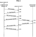
- Fig. 6 is an explanatory diagram showing a connection process sequence.
- the relay device 30 or the communication terminal 20 transmits an RACH (Random Access CHannel) preamble to the base station 10 (S62).
- the base station 10 upon receiving the RACH preamble, acquires TA (Timing Advance) information, and transmits the TA information together with allocation resource information to the relay device 30 or the communication terminal 20 (S64). If the base station 10 is able to grasp the transmission timing of the RACH preamble, for example, the base station 10 can acquire as the TA information the difference between the transmission timing and the reception timing of the RACH preamble.
- the relay device 30 or the communication terminal 20 transmits an RRC connection request to the base station 10 using resources indicated by the allocation resource information (S66).
- the base station 10 upon receiving the RRC connection request, transmits an RRC connection resolution indicating the source of transmission of the RRC connection request (S68). Accordingly, the relay device 30 or the communication terminal 20 is able to check if the base station 10 has received the RRC connection request or not.
- the base station 10 transmits to the management server 16, which has a function of an MME, a connection request indicating that the relay device 30 or the communication terminal 20 is requesting a service (S70).
- the management server 16 upon receiving the connection request, transmits information for performing setup on the relay device 30 or the communication terminal 20 through connection
- the base station 10 transmits RRC connection setup to the relay device 30 or the communication terminal 20 on the basis of the connection setup from the management server 16 (S74), whereupon the relay device 30 or the communication terminal 20 performs a connection setup.
- the relay device 30 or the communication terminal 20 transmits to the base station 10 RRC connection complete indicating that the connection setup is complete (S76).
- connection between the relay device 30 or the communication terminal 20 and the base station 10 is completed, whereby they become able to communicate with each other.
- the aforementioned connection process sequence is only exemplary, and the relay device 30 or the communication terminal 20 and the base station 10 can be connected through another sequence.
- MBSFN Multi-media Broadcasting Single Frequency Network
- MBSFN is a mode in which a plurality of base stations 10 concurrently performs data broadcast transmission using the same frequency.
- the relay device 30 of Type 1 which virtually operates as a base station, transmits a control channel and the like for the DL using the same frequency as that of the base station 10.
- Fig. 7 a specific flow of the MBSFN transmission/reception process will be described with reference to Fig. 7 .
- Fig. 7 is an explanatory diagram showing a specific example of the MBSFN transmission/reception process.
- the base station 10 and the relay device 30 concurrently transmit PDCCH.
- the base station 10 transmits R-PDCCH for controlling the relay in addition to the PDSCH for the communication terminal 20.
- R-PDCCH PDSCH (data to be relayed) for the relay device 30 is transmitted.
- a non-transmission section is provided after the PDSCH for the relay device 30.
- the relay device 30 after transmitting the PDCCH, undergoes a section of switching to a reception process, and receives the PDSCH (data to be relayed) from the base station 10. Then, the relay device 30 switches the reception process to a transmission process in the non-transmission section provided after the PDSCH (data to be relayed) from the base station 10. Further, the relay device 30 adds PDCCH to the decoded PDSCH (data to be relayed) in the next step, and relay-transmits it to the communication terminal 20.
- Fig. 8 is an explanatory diagram showing exemplary frequency allocation to each cell.
- each cell includes three sectors, allocating frequencies f1 to f3 to the respective sectors as shown in Fig. 8 allows interference of the frequencies at the cell boundary to be suppressed.
- Such allocation is particularly effective in a densely populated area with high traffic.
- LTE-A in order to realize high end-to-end throughput, a variety of new technologies have been studied such as spectrum aggregation, network MIMO, uplink multiuser MIMO, and relay technologies. Therefore, with the advent of new mobile applications with high throughput, there is a possibility that frequency resources may become depleted even in suburban areas. Further, in the introduction of LTE-A, there is a possibility that introduction of the relay device 30 may become activated in order to realize low-cost infrastructure development.
- Fig. 9 is an explanatory diagram showing an interference model of a DL being focused in the present embodiment.
- a relay device 30A is located at a position where the relay device 30A is able to receive PDCCH from a plurality of base stations 10 (base stations 10A and 10B), and is located at a position where the relay device 30A is able to receive signals from communication terminals 20 (communication terminals 20A and 20B) belonging the respective base stations 10.
- the relay device 30A can relay both the communication between the base station 10A and the communication terminal 20A and the communication between the base station 10B and the communication terminal 20B.
- the relay device 30A relays a signal transmitted from the base station 10A to the communication terminal 20A without exercising any ingenuity, it is concerned that the signal transmitted by the relay and a signal transmitted from the base station 10B may interfere with each other at the communication terminal 20B.
- Fig. 10 is an explanatory diagram showing an interference model of an UL being focused in the present embodiment.
- a relay device 30A is located at a position where the relay device 30A is able to receive PDCCH from a plurality of base stations 10 (base stations 10A and 10B), and is located at a position where the relay device 30A is able to receive signals from communication terminals 20 (communication terminals 20A and 20B) belonging the respective base stations 10, as in Fig. 9 .
- the relay device 30A can relay both the communication between the base station 10A and the communication terminal 20A and the communication between the base station 10B and the communication terminal 20B.
- the relay device 30A relays a signal transmitted from the communication terminal 20A to the base station 10A without exercising any ingenuity, it is concerned that the signal transmitted by the relay and a signal transmitted from the communication terminal 20B may interfere with each other at the base station 10B.
- the relay device 30 in accordance with the present embodiment has been made with the aforementioned background being focused. Thus, according to the relay device 30, it is possible to adequately select communication to be relayed and suppress generation of interference due to the relay. Hereinafter, the configuration of such relay device 30 in accordance with the present embodiment will be described in conjunction with the configuration of the communication terminal 20.
- Fig. 11 is a functional diagram showing the configuration of the communication terminal 20.
- the communication terminal 20 includes a plurality of antennae 220a to 220n, an analog processing unit 224, an AD/DA converter unit 228, and a digital processing unit 230.
- Each of the plurality of antennae 220a to 220n receives a radio signal from the base station 10 or the relay device 30 and acquires a high-frequency electrical signal, and then supplies the high-frequency signal to the analog processing unit 224. In addition, each of the plurality of antennae 220a to 220n transmits a radio signal to the base station 10 or the relay device 30 on the basis of a high-frequency signal supplied from the analog processing unit 224.
- the communication terminal 20 has a plurality of antennae 220a to 220n as described above, it can perform MIMO (Multiple Input Multiple Output) communication or diversity communication.
- MIMO Multiple Input Multiple Output
- the analog processing unit 224 converts a high-frequency signal transmitted from the plurality of antennae 220a to 220n into a baseband signal by performing analog processing such as amplification, filtering, or down conversion. In addition, the analog processing unit 224 converts a baseband signal supplied from the AD/DA converter unit 228 into a high-frequency signal.
- the AD/DA converter unit 228 converts the baseband signal in an analog format supplied from the analog processing unit 224 into a digital format, and supplies it to the digital processing unit 230. In addition, the AD/DA converter unit 228 converts the baseband signal in a digital format supplied from the digital processing unit 230 into an analog format, and supplies it to the analog processing unit 224.
- the digital processing unit 230 includes a synchronizing unit 232, a decoder 234, an encoder 240, and a control unit 242.
- the synchronizing unit 232, the decoder 234, the encoder 240, and the like function as a communication unit for communicating with the base station 10 or the relay device 30, together with the plurality of antennae 220a to 220n, the analog processing unit 224, and the AD/DA converter unit 228.
- the synchronizing unit 232 is supplied with a synchronization signal such as a PSC or a SSC, which has been transmitted from the base station 10 or the relay device 30, from the AD/DA converter unit 228, and performs a synchronization process on a radio frame on the basis of the synchronization signal. Specifically, the synchronizing unit 232 computes the correlation between the synchronization signal and a known sequence pattern, and detects the peak position of the correlation, thereby synchronizing a radio frame.
- a synchronization signal such as a PSC or a SSC
- the decoder 234 decodes the baseband signal supplied from the AD/DA converter unit 228 to obtain the received data.
- the decoding can include, for example, a MIMO reception process and an OFDM demodulation process.
- the encoder 240 encodes the data to be transmitted such as PUSCH, and supplies it to the AD/DA converter unit 228.
- the encoding can include, for example, a MIMO transmission process and an OFDM modulation process.
- the control unit 242 controls the entire operation in the communication terminal 20 such as a transmission process, a reception process, and a process of connecting to the relay device 30 or the base station 10.
- the communication terminal 20 under the control of the control unit 242, performs a transmission process and a reception process using resource blocks allocated by the base station 10.
- the control unit 242 controls a transmission process in accordance with a transmission parameter specified by the base station 10 or the relay device 30.
- the control unit 242 controls a transmission process in accordance with the TPC parameter specified by the base station 10.
- the digital processing unit 230 measures the channel quality (e.g., received power) using a demodulation reference transmitted from the base station 10 or the relay device 30.
- the control unit 242 generates a CQI report on the basis of the aforementioned measurement result, and supplies the generated CQI report to the encoder 240. Consequently, the CQI report is transmitted to the base station 10 or the relay device 30 using PUSCH.
- Fig. 12 is a functional block diagram showing the configuration of the relay device 30.
- the relay device 30 includes a plurality of antennae 320a to 320n, an analog processing unit 324, an AD/DA converter unit 328, and a digital processing unit 330.
- Each of the plurality of antennae 320a to 320n receives a radio signal from the base station 10 or the communication terminal 20 and acquires a high-frequency electrical signal, and then supplies the high-frequency signal to the analog processing unit 324. In addition, each of the plurality of antennae 320a to 320n transmits a radio signal to the base station 10 or the communication terminal 20 on the basis of a high-frequency signal supplied from the analog processing unit 324.
- the relay device 30 has a plurality of antennae 320a to 320n as described above, it can perform MIMO communication or diversity communication.
- the analog processing unit 324 converts a high-frequency signal supplied from the plurality of antennae 320a to 320n into a baseband signal by performing analog processing such as amplification, filtering, or down conversion. In addition, the analog processing unit 324 converts a baseband signal supplied from the AD/DA converter unit 328 into a high-frequency signal.
- the AD/DA converter unit 328 converts the baseband signal in an analog format supplied from the analog processing unit 324 into a digital format, and supplies it to the digital processing unit 330. In addition, the AD/DA converter unit 328 converts the baseband signal in a digital format supplied from the digital processing unit 330 into an analog format, and supplies it to the analog processing unit 324.
- the digital processing unit 330 includes a synchronizing unit 332, a decoder 334, a buffer 338, an encoder 340, a control unit 342, a relay selection unit 344, a distance estimation unit 346, and a power setting unit 348.
- the synchronizing unit 332, the decoder 334, the encoder 340, and the like function as a receiving unit, a transmitting unit, and a relay unit for communicating with the base station 10 or the communication terminal 20, together with the plurality of antennae 320a to 320n, the analog processing unit 324, and the AD/DA converter unit 328.
- the synchronizing unit 332 is supplied with a synchronization signal, which has been transmitted from the base station 10, from the AD/DA converter unit 328, and performs a synchronization process on a radio frame on the basis of the synchronization signal. Specifically, the synchronizing unit 332 computes the correlation between the synchronization signal and a known sequence pattern, and detects the peak position of the correlation, thereby synchronizing a radio frame.
- the decoder 334 decodes the baseband signal supplied from the AD/DA converter unit 328, and obtains relay data addressed to the base station 10 or to the communication terminal 20.
- the decoding can include, for example, a MIMO reception process, an OFDM demodulation process, and an error correction process.
- the buffer 338 temporally stores the relay data addressed to the base station 10 or to the communication terminal 20 obtained by the decoder 334. Then, under the control of the control unit 342, the relay data addressed to the communication terminal 20 is read from the buffer 338 into the encoder 340 using resource blocks for the DL of the access link. Likewise, under the control of the control unit 342, the relay data addressed to the base station 10 is read from the buffer 338 into the encoder 340 using resource block for the UL of the relay link.
- the encoder 340 encodes the relay data supplied from the buffer 338, and supplies it to the AD/DA converter unit 328.
- the encoding can include, for example, a MIMO transmission process and OFDM modulation process.
- the relay selection unit 344 when the relay device 30 is located at a position where the relay device 30 is able to relay a plurality of communications, selects any of or all of the communications as the communication to be relayed.
- the relay selection unit 344 of the relay device 30A shown in Fig. 9 selects which of the communication between the base station 10A and the communication terminal 20A and the communication between the base station 10B and the communication terminal 20B is to be relayed.
- the criteria of selection by the relay selection unit 344 will be specifically described.
- the relay selection unit 344 acquires scheduling information for an UL toward each base station 10 from the PDCCH.
- the relay selection unit 344 acquires a CQI report from the PUSCH. Note that the relay selection unit 344 can determine from which of the communication terminals 20 each PUSCH has been transmitted on the basis of the scheduling information for the UL.
- the relay selection unit 344 selects the communication to be relayed on the basis of the acquired CQI report (communication quality information).
- the relay selection unit 344 can preferentially select the communication of the direct link with worse communication quality in each of the UL and the DL.
- the relay selection unit 344 can select the DL communication in the direction from the base station 10A to the communication terminal 20A. That is, the relay selection unit 344 can select the DL communication in the direction from the base station 10A to the communication terminal 20A as the target to be relayed when "CQI_level_communication terminal 20A ⁇ CQI_level_communication terminal 20B.”
- the relay selection unit 344 can select the UL communication in the direction from the communication terminal 20A to the base station 10A. That is, the relay selection unit 344 can select the UL communication in the direction from the communication terminal 20A to the base station 10A as the target to be relayed when "CQI_level_communication terminal 20A ⁇ CQI_level_communication terminal 20B.”
- the relay selection unit 344 determines the communication with bad communication quality on the basis of the CQI report
- the present embodiment is not limited thereto.
- the TPC parameter specified by the base station 10 for the communication terminal 20 changes in accordance with the state of the direct link between the base station 10 and the communication terminal 20
- the TPC parameter can also be recognized as an index indicating the communication quality of the direct link.
- the relay selection unit 344 can preferentially select communication, which is specifically performed with a high output signal, as the target to be relayed on the basis of the TPC parameter specified through PDCCH by the base station 10 for the communication terminal 20.
- the distance estimation unit 346 estimates the distance from each base station 10 and the distance from each communication terminal 20 located in the range in which communication is possible. For example, the distance estimation unit 346 of the relay device 30A shown in Fig. 9 estimates the distance from the base station 10A, the distance from the base station 10B, the distance from the communication terminal 20A, and the distance from the communication terminal 20B.
- the distance estimation unit 346 estimates the distance on the basis of a propagation loss of a reference signal whose transmission power and phase are known, transmitted from each base station 10 and each communication terminal 20. For example, the distance estimation unit 346 can calculate a propagation loss of a reference signal (demodulation reference) transmitted from the communication terminal 20A and estimate the distance from the communication terminal 20A on the basis of the calculated propagation loss. Similarly, the distance estimation unit 346 can calculate a propagation loss of a reference signal transmitted from the base station 10B and estimate the distance from the base station 10B on the basis of the calculated propagation loss.
- a reference signal demodulation reference
- the power setting unit 348 sets transmission power for performing the relay selected by the relay selection unit 344.
- transmission power set by the power setting unit 348 in each of a case in which the target to be relayed is the DL communication and a case in which the target to be relayed is the UL communication will be described.
- the power setting unit 348 sets the transmission power of a signal for the communication terminal 20A so that interference would not be generated at the communication terminal 20B. Specifically, the power setting unit 348 can set the transmission power so that Qos expected by the base station 10A/communication terminal 20A is satisfied and also Formula 1 below is satisfied. [Math. 1] Transmission power dB ⁇ permissible interference level of the communication terminal 20 B dB + propagation loss between the relay device 30 A and the communication terminal 20 B dB
- the permissible interference level of the communication terminal 20B can be the SINR required at the minimum rate of the communication terminal 20B indicated by device authentication institutions.
- the power setting unit 348 can estimate a propagation loss between the relay device 30A and the communication terminal 20B on the basis of the distance between the relay device 30A and the communication terminal 20B estimated by the distance estimation unit 346. Note that the power setting unit 348 can set the minimum transmission power within the range that Qos expected by the base station 10A/communication terminal 20A is satisfied and also Formula 1 above is satisfied, in view of reducing the power consumption.
- the relay device 30 When the transmission power that satisfies Formula 1 above is absent, the relay device 30 need not perform the relay. Alternatively, when the relay device 30 is authorized to schedule resources, it can reallocate the resource blocks so that interference will not be generated.
- the power setting unit 348 sets the transmission power of a signal for the base station 10A so that interference would not be generated at the base station 10B. Specifically, the power setting unit 348 can set the transmission power so that Qos expected by the base station 10A/communication terminal 20A is satisfied and also Formula 2 below is satisfied. [Math. 2] Transmission powert dB ⁇ permissible interference level of the base station 10 B dB + propagation loss between the relay device 30 A and the base station 10 B dB
- the permissible interference level of the base station 10B can be the SINR required at the minimum rate of the base station 10B indicated by device authentication institutions.
- the power setting unit 348 can estimate a propagation loss between the relay device 30A and the base station 10B on the basis of the distance between the relay device 30A and the base station 10B estimated by the distance estimation unit 346. Note that the power setting unit 348 can set the minimum transmission power within the range that Qos expected by the base station 10A/communication terminal 20A is satisfied and also Formula 2 above is satisfied, in view of reducing the power consumption.
- the relay device 30 When the transmission power that satisfies Formula 2 above is absent, the relay device 30 need not perform the relay. Alternatively, when the relay device 30 is authorized to schedule resources, it can reallocate the resource blocks so that interference will not be generated.
- the control unit 342 controls the transmission process so that a signal for relay is transmitted to the base station 10 or the communication terminal 20 selected by the relay selection unit 344 using the transmission power set by the power setting unit 348. Further, the control unit 342 can, in controlling the transmission process, control a transmission parameter such as an AMC (Advanced Modulation and Coding) parameter or a HARQ (Hybrid Automatic Repeat Request) parameter in a manner described below. Note that the control below can be performed either alone or in combination.
- AMC Advanced Modulation and Coding
- HARQ Hybrid Automatic Repeat Request
- the control unit 342 can perform overlay transmission of a relay signal using a Modulation-Coding parameter with a higher rate than that of the direct link.
- the signal transmitted through the direct link is buried when received by the communication terminal 20, but it is expected that the relay signal from the relay device 30 be decoded by the communication terminal 20.
- the relay device 30 can also transmit a relay signal using a Modulation-Coding parameter with a higher rate than that of the direct link, utilizing available time slots.
- the control unit 342 can perform overlay transmission of a relay signal using the same parameter as that of the retransmission packets.
- the relay device 30 can also transmit a relay signal as a HARQ packet at a higher rate than that of the direct link utilizing available time slots.
- the control unit 342 can estimate the relative direction of the communication terminal 20, which is the relay destination, the control unit 342 can transmit a relay signal through beam forming.
- the power setting unit 348 can set the transmission power on the basis of the transmission power and propagation loss of a Null beam for a communication terminal 20 that is not the relay destination. According to such beam forming, it becomes possible to select a plurality of communication terminals 20 as the relay destinations and concurrently transmit relay signals to the plurality of communication terminals 20.
- the control unit 342 can perform overlay transmission of a relay signal using a Modulation-Coding parameter with a higher rate than that of the direct link.
- the signal transmitted through the direct link is buried when received by the base station 10, but it is expected that the relay signal from the relay device 30 be decoded by the base station 10.
- the relay device 30 can also transmit a relay signal using a Modulation-Coding parameter with a higher rate than that of the direct link, utilizing available time slots.
- the control unit 342 can perform overlay transmission of a relay signal using the same parameter as that of the retransmission packets.
- the relay device 30 can also transmit a relay signal as a HARQ packet at a higher rate than that of the direct link utilizing available time slots.
- the control unit 342 can estimate the relative direction of the base station 10, which is the relay destination, the control unit 342 can transmit a relay signal through beam forming.
- the power setting unit 348 can set the transmission power on the basis of the transmission power and propagation loss of a Null beam for a base station 10 that is not the relay destination. According to such beam forming, it becomes possible to select a plurality of base stations 10 as the relay destinations and concurrently transmit relay signals to the plurality of base stations 10.
- Fig. 13 is a sequence diagram showing a flow in which the relay device 30 relays the DL communication.
- the relay device 30 upon receiving PDCCH from the base station 10A (S404) and receiving PDCCH from the base station 10B (S408), acquires scheduling information from each PDCCH (S412).
- the relay device 30 upon receiving a demodulation reference from the communication terminal 20A (S416) and receiving a demodulation reference from the communication terminal 20B (S420), estimates the distance from the communication terminal 20A and the distance from the communication terminal 20B on the basis of a propagation loss of each demodulation reference (S424). Note that it is possible to determine from which communication terminal 20 each demodulation reference has been transmitted on the basis of the scheduling information acquired in S412.
- the relay selection unit 344 selects which of the communication directed to the communication terminal 20A and the communication directed to the communication terminal 20B is to be relayed on the basis of the communication quality indicated by the CQI report (S436). For example, the relay selection unit 344 can preferentially select communication with bad communication quality.
- the power setting unit 348 sets the transmission power of a signal for the communication terminal 20 selected in S436 so that the reception level at the other communication terminal 20 becomes less than or equal to the permissible interference level of the other communication terminal 20 (S440). Then, when the communication terminal 20A is selected in S436, the relay device 30, upon receiving PDSCH from the base station 10A (S444), transmits the received PDSCH to the communication terminal 20A using the transmission power set by the power setting unit 348 (S448). Note that the relay device 30 can transmit the PDSCH to the communication terminal 20A by adequately controlling a parameter such as AMC or
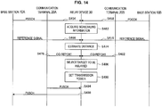
- Fig. 14 is a sequence diagram showing a flow in which the relay device 30 relays the UL communication.
- the relay device 30 upon receiving PDCCH from the base station 10A (S454) and receiving PDCCH from the base station 10B (S458), acquires scheduling information from each PDCCH (S462).
- the relay device 30 upon receiving a reference signal from the base station 10A (S466) and receiving a reference signal from the base station 10B (S470), estimates the distance from the base station 10A and the distance from the base station 10B on the basis of a propagation loss of each reference signal (S474).
- the relay selection unit 344 selects which of the communication directed to the base station 10A and the communication directed to the base station 10B is to be relayed on the basis of the communication quality indicated by the CQI report (S486). For example, the relay selection unit 344 can preferentially select communication with bad communication quality.
- the power setting unit 348 sets the transmission power of a signal for the base station 10 selected in S486 so that the reception level at the other base station 10 becomes less than or equal to the permissible interference level of the other base station 10 (S490). Then, when the base station 10A is selected in S486, the relay device 30, upon receiving PUSCH from the communication terminal 20A (S494), transmits the received PUSCH to the base station 10A using the transmission power set by the power setting unit 348 (S498). Note that the relay device 30 can transmit the PDSCH to the communication terminal 20A by adequately controlling a parameter such as AMC or HARQ.
- the relay device 30 in accordance with the present embodiment can, when a plurality of base stations 10 and communication terminals 20 exist in the range in which communication is possible, adequately select the communication to be relayed. Further, the relay device 30 in accordance with the present embodiment can transmit a relay signal using transmission power that would not cause interference at a base station 10 or a communication terminal 20 that is not the relay destination.
- the steps in the process of the communication system 1 in this specification need not necessarily be processed in a time-series order in accordance with the order described in the sequence diagram.
- the steps in the process of the communication system 1 can be performed in an order different from that described in the sequence diagram, or be processed in parallel.
- S404 and S408 in Fig. 13 can be concurrently received by the relay device 30 or one of them can be received earlier.
- S454 and S458, S466 and S470, and S478 and S482 in Fig. 14 .
- a storage medium having the computer program stored therein is also provided.
Landscapes
- Engineering & Computer Science (AREA)
- Signal Processing (AREA)
- Computer Networks & Wireless Communication (AREA)
- Quality & Reliability (AREA)
- Physics & Mathematics (AREA)
- Electromagnetism (AREA)
- Mobile Radio Communication Systems (AREA)
- Radio Relay Systems (AREA)
Claims (7)
- Kommunikationssystem (1), umfassend:mehrere Basisstationen (10);mehrere Kommunikationsendgeräte (20), die mit einer der mehreren Basisstationen (10) kommunizieren; undeine Weiterleitungseinrichtung (30), wobei die Weiterleitungseinrichtung (30) Folgendes beinhaltet:
eine Auswahleinheit (334), die ein weiterzuleitendes Kommunikationsendgerät (20) aus den mehreren Kommunikationsendgeräten (20) auf Basis von Kommunikationsqualitätsinformationen auswählt, die von jedem der mehreren Kommunikationsendgeräte (20) empfangen werden, und eine Weiterleitungseinheit, die eine Kommunikation zwischen dem durch die Auswahleinheit (334) ausgewählten Kommunikationsendgerät (20) und der entsprechenden Basisstation (10) weiterleitet, wobei die Weiterleitungseinrichtung (30) ferner eine Leistungseinstellungseinheit (348) beinhaltet, die eine Übertragungsleistung eines Weiterleitungssignals für das weiterzuleitende Kommunikationsendgerät (20) einstellt, sodass eine Differenz zwischen der Übertragungsleistung und einem Ausbreitungsverlust des Weiterleitungssignals zwischen einem anderen Kommunikationsendgerät (20) und der Weiterleitungseinrichtung (30) unter einem vorbestimmten Wert liegt. - Kommunikationssystem nach Anspruch 1, wobei die Weiterleitungseinrichtung (30) ferner eine Abstandsschätzungseinheit (346) beinhaltet, die einen Abstand zwischen der Weiterleitungseinrichtung (30) und dem anderen Kommunikationsendgerät (20) auf Basis eines Ausbreitungsverlustes eines Referenzsignals, das von dem anderen Kommunikationsendgerät (20) empfangen wird, schätzt, wobei das Referenzsignal eine bekannte Übertragungsleistung aufweist, und die Leistungseinstellungseinheit (348) einen Ausbreitungsverlust des Weiterleitungssignals zwischen dem anderen Kommunikationsendgerät (20) und der Weiterleitungseinrichtung (30) auf Basis des durch die Abstandsschätzungseinheit (346) geschätzten Abstands schätzt.
- Kommunikationssystem nach Anspruch 1 oder 2, wobei die Auswahleinheit (334) ein Kommunikationsendgerät (20) mit einer schlechten Kommunikationsqualität aus den mehreren Kommunikationsendgeräten (20) auswählt.
- Kommunikationssystem nach einem der Ansprüche 1 bis 3, wobei die Weiterleitungseinrichtung das Weiterleitungssignal für das weiterzuleitende Kommunikationsendgerät (20) durch Strahlformung überträgt.
- Kommunikationssystem nach einem der Ansprüche 1 bis 4, wobei die Weiterleitungseinrichtung (30) ferner eine Leistungseinstellungseinheit beinhaltet, die eine Übertragungsleistung eines Weiterleitungssignals für eine Basisstation (10) entsprechend dem weiterzuleitenden Kommunikationsendgerät (20) einstellt, sodass eine Differenz zwischen der Übertragungsleistung und einem Ausbreitungsverlust des Weiterleitungssignals zwischen einer anderen Basisstation (10) und der Weiterleitungseinrichtung (30) unter einem vorbestimmten Wert liegt.
- Kommunikationssystem nach Anspruch 5, wobei die Weiterleitungseinrichtung (30) ferner eine Abstandsschätzungseinheit (346) beinhaltet, die einen Abstand zwischen der Weiterleitungseinrichtung (30) und der anderen Basisstation (10) auf Basis eines Ausbreitungsverlustes eines Referenzsignals, das von der anderen Basisstation (10) empfangen wird, schätzt, wobei das Referenzsignal eine bekannte Übertragungsleistung aufweist, und
die Leistungseinstellungseinheit (348) einen Ausbreitungsverlust des Weiterleitungssignals zwischen der anderen Basisstation (10) und der Weiterleitungseinrichtung (30) auf Basis des durch die Abstandsschätzungseinheit (346) geschätzten Abstands schätzt. - Weiterleitungseinrichtung (30), umfassend:eine Auswahleinheit (344), die ein weiterzuleitendes Kommunikationsendgerät (20) aus mehreren Kommunikationsendgeräten auf Basis von Kommunikationsqualitätsinformationen auswählt, die von jedem der mehreren Kommunikationsendgeräte (20), die mit einer von mehreren Basisstationen (10) kommunizieren, empfangen werden;eine Weiterleitungseinheit, die eine Kommunikation zwischen dem durch die Auswahleinheit (344) ausgewählten Kommunikationsendgerät (20) und der entsprechenden Basisstation (10) weiterleitet,eine Leistungseinstellungseinheit (348), die eine Übertragungsleistung eines Weiterleitungssignals für das weiterzuleitende Kommunikationsendgerät (20) einstellt, sodass eine Differenz zwischen der Übertragungsleistung und einem Ausbreitungsverlust des Weiterleitungssignals zwischen einem anderen Kommunikationsendgerät (20) und der Weiterleitungseinrichtung (30) unter einem vorbestimmten Wert liegt.
Priority Applications (1)
| Application Number | Priority Date | Filing Date | Title |
|---|---|---|---|
| EP18193131.2A EP3468065A1 (de) | 2009-09-25 | 2010-08-16 | Relaisvorrichtung und methode |
Applications Claiming Priority (2)
| Application Number | Priority Date | Filing Date | Title |
|---|---|---|---|
| JP2009220483A JP5515558B2 (ja) | 2009-09-25 | 2009-09-25 | 通信システム、中継装置および通信装置 |
| PCT/JP2010/063808 WO2011036965A1 (ja) | 2009-09-25 | 2010-08-16 | 通信システム、中継装置、通信端末および基地局 |
Related Child Applications (2)
| Application Number | Title | Priority Date | Filing Date |
|---|---|---|---|
| EP18193131.2A Division-Into EP3468065A1 (de) | 2009-09-25 | 2010-08-16 | Relaisvorrichtung und methode |
| EP18193131.2A Division EP3468065A1 (de) | 2009-09-25 | 2010-08-16 | Relaisvorrichtung und methode |
Publications (3)
| Publication Number | Publication Date |
|---|---|
| EP2472983A1 EP2472983A1 (de) | 2012-07-04 |
| EP2472983A4 EP2472983A4 (de) | 2015-10-28 |
| EP2472983B1 true EP2472983B1 (de) | 2018-10-17 |
Family
ID=43795724
Family Applications (2)
| Application Number | Title | Priority Date | Filing Date |
|---|---|---|---|
| EP18193131.2A Withdrawn EP3468065A1 (de) | 2009-09-25 | 2010-08-16 | Relaisvorrichtung und methode |
| EP10818641.2A Not-in-force EP2472983B1 (de) | 2009-09-25 | 2010-08-16 | Kommunikationssystem, relaisvorrichtung, kommunikationsendgerät und basisstation |
Family Applications Before (1)
| Application Number | Title | Priority Date | Filing Date |
|---|---|---|---|
| EP18193131.2A Withdrawn EP3468065A1 (de) | 2009-09-25 | 2010-08-16 | Relaisvorrichtung und methode |
Country Status (8)
| Country | Link |
|---|---|
| US (4) | US8976725B2 (de) |
| EP (2) | EP3468065A1 (de) |
| JP (1) | JP5515558B2 (de) |
| CN (1) | CN102511194B (de) |
| BR (1) | BR112012006061A2 (de) |
| IN (1) | IN2012DN02290A (de) |
| RU (1) | RU2549199C2 (de) |
| WO (1) | WO2011036965A1 (de) |
Families Citing this family (29)
| Publication number | Priority date | Publication date | Assignee | Title |
|---|---|---|---|---|
| US6807405B1 (en) | 1999-04-28 | 2004-10-19 | Isco International, Inc. | Method and a device for maintaining the performance quality of a code-division multiple access system in the presence of narrow band interference |
| US8385483B2 (en) | 2008-11-11 | 2013-02-26 | Isco International, Llc | Self-adaptive digital RF bandpass and bandstop filter architecture |
| JP5515558B2 (ja) * | 2009-09-25 | 2014-06-11 | ソニー株式会社 | 通信システム、中継装置および通信装置 |
| CN102273118B (zh) * | 2011-04-18 | 2016-06-22 | 华为终端有限公司 | 数据重传的方法、装置及系统 |
| CN102368866B (zh) * | 2011-09-15 | 2013-04-17 | 上海交通大学 | 基于网络编码的多接入中继信道中的单中继选择方法 |
| CN102438250B (zh) * | 2011-11-10 | 2014-08-20 | 北京邮电大学 | 采用协作模拟网络编码技术抑制小区间干扰的方法 |
| CN103458426B (zh) * | 2012-06-04 | 2016-02-10 | 中兴通讯股份有限公司 | 一种为用户终端选取译码转发式中继节点的方法及装置 |
| EP2890193B1 (de) * | 2012-08-24 | 2018-05-23 | Fujitsu Limited | Funkkommunikationsverfahren, funkkommunikationssystem, funkbasisstation und funkendgerät |
| US9319916B2 (en) | 2013-03-15 | 2016-04-19 | Isco International, Llc | Method and appartus for signal interference processing |
| CN105230070B (zh) * | 2013-06-03 | 2019-05-03 | 华为技术有限公司 | 一种无线资源分配方法以及无线资源分配装置 |
| CN104254114A (zh) | 2013-06-27 | 2014-12-31 | 华为终端有限公司 | 一种网络接入方法、设备及系统 |
| US9794888B2 (en) | 2014-05-05 | 2017-10-17 | Isco International, Llc | Method and apparatus for increasing performance of a communication link of a communication node |
| KR102362445B1 (ko) * | 2014-06-20 | 2022-02-14 | 소니그룹주식회사 | 장치 및 방법 |
| EP3209051B1 (de) * | 2014-10-17 | 2021-10-27 | Sony Group Corporation | Vorrichtung |
| EP3292642B1 (de) | 2015-05-04 | 2020-01-29 | ISCO International, LLC | Verfahren und vorrichtung zur erhöhung der leistung von übertragungswegen für übertragungsknoten |
| EP3160194B1 (de) | 2015-10-21 | 2018-08-08 | Alcatel Lucent | Vorrichtungen, verfahren und computerprogramme zur bestimmung der übertragungssteuerungsinformationen |
| US11233586B2 (en) * | 2016-03-18 | 2022-01-25 | Kyocera Corporation | Providing user equipment feedback via signal forwarding device |
| US10652835B2 (en) | 2016-06-01 | 2020-05-12 | Isco International, Llc | Signal conditioning to mitigate interference impacting wireless communication links in radio access networks |
| KR102493536B1 (ko) | 2016-06-08 | 2023-01-31 | 삼성전자주식회사 | 통신 단말의 릴레이 통신 방법 및 그 통신 단말 |
| US10298279B2 (en) | 2017-04-05 | 2019-05-21 | Isco International, Llc | Method and apparatus for increasing performance of communication paths for communication nodes |
| US10812121B2 (en) | 2017-08-09 | 2020-10-20 | Isco International, Llc | Method and apparatus for detecting and analyzing passive intermodulation interference in a communication system |
| US10284313B2 (en) | 2017-08-09 | 2019-05-07 | Isco International, Llc | Method and apparatus for monitoring, detecting, testing, diagnosing and/or mitigating interference in a communication system |
| CN107682907A (zh) * | 2017-10-23 | 2018-02-09 | 蒋丁贵 | 一种中继装置及信息转发方法 |
| US11924753B2 (en) | 2019-08-01 | 2024-03-05 | Qualcomm Incorporated | Power saving of smart repeaters based on a triggering signal |
| US12375943B2 (en) * | 2019-08-01 | 2025-07-29 | Qualcomm Incorporated | Power saving of smart repeaters |
| US11758465B2 (en) * | 2019-12-17 | 2023-09-12 | Qualcomm Incorporated | Repeater beacon signal for enabling inter-cell interference coordination |
| CN113382423B (zh) * | 2020-03-09 | 2023-08-22 | 维沃移动通信有限公司 | 信号传输方法、信息指示方法和相关设备 |
| US12471077B2 (en) * | 2021-04-12 | 2025-11-11 | Qualcomm Incorporated | Measurement and power control in integrated access fronthaul networks |
| JPWO2023281671A1 (de) * | 2021-07-07 | 2023-01-12 |
Family Cites Families (50)
| Publication number | Priority date | Publication date | Assignee | Title |
|---|---|---|---|---|
| DE69839666D1 (de) * | 1997-03-03 | 2008-08-14 | Iwics Inc | Zellulares kommunikationssystem in dem mobilstationen als relaisstationen dienen |
| JP2001028566A (ja) * | 1999-07-12 | 2001-01-30 | Ntt Docomo Inc | 無線回線中継方法及びその装置 |
| CN101257659B (zh) * | 2002-06-06 | 2011-04-06 | 株式会社Ntt都科摩 | 分组通信系统、分组通信方法、基站、移动站、控制装置 |
| US8593932B2 (en) * | 2003-05-16 | 2013-11-26 | Qualcomm Incorporated | Efficient signal transmission methods and apparatus using a shared transmission resource |
| US8908609B1 (en) * | 2003-06-06 | 2014-12-09 | Rockstar Consortium Us Lp | Multi-hop wireless communications system and method |
| US7542453B2 (en) * | 2004-01-08 | 2009-06-02 | Sony Corporation | Wireless communication system, wireless communication apparatus, wireless communication method, and computer program |
| US7548517B2 (en) * | 2005-04-25 | 2009-06-16 | Motorola, Inc. | Method and apparatus for determining the location of a node in a wireless system |
| CN100555930C (zh) * | 2005-07-04 | 2009-10-28 | 上海原动力通信科技有限公司 | 多载波hsdpa的信道建立方法和多载波下行分组数据传输方法 |
| CN1893342B (zh) * | 2005-07-05 | 2010-06-09 | 上海原动力通信科技有限公司 | 多载波hsdpa的业务传输信道编码方法和编码装置 |
| CN1953406B (zh) * | 2005-10-19 | 2011-06-01 | 株式会社Ntt都科摩 | 接入混合网的方法和网关设备、无线终端以及通信系统 |
| KR20070045385A (ko) * | 2005-10-27 | 2007-05-02 | 삼성전자주식회사 | 다중 홉 릴레이 방식의 광대역 무선 통신 시스템에서전파지연 및 처리지연 측정을 통한 송수신 전력을 제어하기위한 장치 및 방법 |
| CN101322327B (zh) * | 2005-11-29 | 2012-11-14 | 艾利森电话股份有限公司 | 用于在无线中继网络中中继信息的方法、设备和系统 |
| US7872992B2 (en) * | 2005-12-09 | 2011-01-18 | Panasonic Corporation | Network system and relay device |
| EP1801995A1 (de) * | 2005-12-21 | 2007-06-27 | Fujitsu Limited | Signalisierung in Mehrsprungkommunikationssystemen |
| US20070177545A1 (en) * | 2006-01-30 | 2007-08-02 | Natarajan Kadathur S | System and method for allocating sub-channels in a network |
| KR100756985B1 (ko) * | 2006-08-30 | 2007-09-07 | 삼성전자주식회사 | 광대역 무선통신 시스템에서 중계국을 선택하기 위한 장치및 방법 |
| US7978667B2 (en) * | 2006-11-30 | 2011-07-12 | Kyocera Corporation | Management of WLAN and WWAN communication services to a multi-mode wireless communication device |
| US8103285B2 (en) * | 2007-04-19 | 2012-01-24 | Kyocera Corporation | Apparatus, system and method for determining a geographical location of a portable communication device |
| JP4898911B2 (ja) * | 2007-05-11 | 2012-03-21 | パナソニック株式会社 | 無線通信方法、無線通信装置、無線通信システム、および中継方法 |
| WO2008144859A1 (en) * | 2007-05-30 | 2008-12-04 | Ericsson Telecomunicações S.A. | Method and arrangement for resource allocation |
| JP5529018B2 (ja) * | 2007-07-06 | 2014-06-25 | ゼットティーイー(ユーエスエー)インコーポレーテッド | 無線マルチホップ中継ネットワークにおけるリソース割当 |
| EP2245760B1 (de) * | 2007-08-24 | 2017-10-04 | BlackBerry Limited | Leistungssteuerung an einer relaisstation in einem drahtlosen netzwerk |
| JP5067427B2 (ja) * | 2007-12-05 | 2012-11-07 | 富士通株式会社 | パラメータ収集方法、無線基地局、及び、中継局 |
| CN101494899B (zh) | 2008-01-25 | 2010-12-08 | 中兴通讯股份有限公司 | 一种具有中继站的无线通信网络中小区间干扰协调方法 |
| EP2241719A1 (de) | 2008-01-29 | 2010-10-20 | Panasonic Corporation | Entspannerintegrierter verdichter und diesen verwendender kältekreislauf |
| JP2011077563A (ja) * | 2008-02-01 | 2011-04-14 | Panasonic Corp | 無線中継装置および無線送受信装置、無線中継方法および無線送受信方法、リレーノードおよび基地局 |
| CN101272173B (zh) * | 2008-05-09 | 2012-10-10 | 中兴通讯股份有限公司 | 路损补偿因子设置方法 |
| US9236933B2 (en) * | 2008-05-23 | 2016-01-12 | Electronics And Telecommunications Research Institute | Apparatus and method for transmitting and receiving data using multi-path in wireless communication system of distributed MAC |
| CN101325549B (zh) * | 2008-06-06 | 2011-05-04 | 北京邮电大学 | 在无线中继网络中采用网络编码通信的方法 |
| US9078270B2 (en) * | 2008-07-03 | 2015-07-07 | Qualcomm Incorporated | Opportunistic relay scheduling in wireless communications |
| US9615354B2 (en) * | 2008-07-17 | 2017-04-04 | Nokia Solutions And Networks Oy | Device-to-device communications in cellular system |
| US8289894B2 (en) * | 2008-09-15 | 2012-10-16 | Sharp Laboratories Of America, Inc. | Systems and methods for inter relay interference coordination |
| WO2010034349A1 (en) * | 2008-09-26 | 2010-04-01 | Nokia Siemens Networks Oy | Control signaling in system supporting relayed connections |
| JP2010087828A (ja) * | 2008-09-30 | 2010-04-15 | Fujitsu Ltd | 近距離mimoリピータ装置、近距離mimo携帯端末装置、近距離mimo無線通信方法 |
| KR101571564B1 (ko) * | 2008-11-12 | 2015-11-25 | 엘지전자 주식회사 | 데이터 전송 방법 |
| US8886113B2 (en) * | 2008-12-30 | 2014-11-11 | Qualcomm Incorporated | Centralized control of relay operation |
| KR101639240B1 (ko) * | 2009-03-03 | 2016-07-13 | 삼성전자주식회사 | 랜덤 빔포밍 기술을 이용하여 간섭 제어를 수행하는 통신 시스템 및 통신 방법 |
| KR101512688B1 (ko) * | 2009-04-13 | 2015-04-17 | 삼성전자주식회사 | 통신 장치 및 중계 장치 |
| KR101645490B1 (ko) * | 2009-05-07 | 2016-08-05 | 엘지전자 주식회사 | 무선 통신 시스템에서 소정의 cp길이를 가지는 프레임을 이용하여 신호를 전송하는 방법 |
| JP5359613B2 (ja) * | 2009-06-30 | 2013-12-04 | 富士通株式会社 | 無線通信ネットワーク及び方法 |
| KR101813847B1 (ko) * | 2009-07-13 | 2018-01-02 | 엘지전자 주식회사 | 기지국의 신호 전송 방법 및 장치 |
| JP5540592B2 (ja) * | 2009-07-23 | 2014-07-02 | ソニー株式会社 | 通信システム、通信制御方法、移動端末、および中継装置 |
| JP5418042B2 (ja) * | 2009-07-27 | 2014-02-19 | 富士通株式会社 | 通信制御装置、移動端末装置および無線通信方法 |
| US8774253B2 (en) * | 2009-07-28 | 2014-07-08 | Panasonic Corporation | Wireless relay device and wireless relay method |
| JP5515558B2 (ja) * | 2009-09-25 | 2014-06-11 | ソニー株式会社 | 通信システム、中継装置および通信装置 |
| JP5521638B2 (ja) | 2009-09-25 | 2014-06-18 | ソニー株式会社 | 通信システム、中継装置、管理サーバ、および通信端末 |
| JP5440117B2 (ja) * | 2009-11-20 | 2014-03-12 | 富士通株式会社 | 無線通信システム、移動中継局、移動局及び無線通信方法 |
| JP5485819B2 (ja) * | 2010-07-01 | 2014-05-07 | 京セラ株式会社 | 無線中継装置及び制御方法 |
| CN102340784B (zh) * | 2010-07-16 | 2014-11-05 | 上海贝尔股份有限公司 | 选择用户终端以增强上下行互逆误差校准的方法和装置 |
| JP5374743B2 (ja) * | 2010-12-15 | 2013-12-25 | 株式会社日立製作所 | 無線ネットワークシステム、及び、無線通信装置 |
-
2009
- 2009-09-25 JP JP2009220483A patent/JP5515558B2/ja not_active Expired - Fee Related
-
2010
- 2010-08-16 EP EP18193131.2A patent/EP3468065A1/de not_active Withdrawn
- 2010-08-16 WO PCT/JP2010/063808 patent/WO2011036965A1/ja not_active Ceased
- 2010-08-16 EP EP10818641.2A patent/EP2472983B1/de not_active Not-in-force
- 2010-08-16 CN CN201080041237.4A patent/CN102511194B/zh not_active Expired - Fee Related
- 2010-08-16 IN IN2290DEN2012 patent/IN2012DN02290A/en unknown
- 2010-08-16 US US13/496,499 patent/US8976725B2/en not_active Expired - Fee Related
- 2010-08-16 RU RU2012110184/07A patent/RU2549199C2/ru not_active IP Right Cessation
- 2010-08-16 BR BR112012006061A patent/BR112012006061A2/pt not_active Application Discontinuation
-
2015
- 2015-02-02 US US14/612,052 patent/US9402222B2/en not_active Expired - Fee Related
-
2016
- 2016-07-05 US US15/202,285 patent/US10063279B2/en active Active
-
2018
- 2018-08-09 US US16/059,579 patent/US10965341B2/en not_active Expired - Fee Related
Also Published As
| Publication number | Publication date |
|---|---|
| US10063279B2 (en) | 2018-08-28 |
| US8976725B2 (en) | 2015-03-10 |
| JP2011071705A (ja) | 2011-04-07 |
| US9402222B2 (en) | 2016-07-26 |
| US20160315658A1 (en) | 2016-10-27 |
| RU2012110184A (ru) | 2013-09-27 |
| BR112012006061A2 (pt) | 2016-03-29 |
| CN102511194B (zh) | 2015-12-02 |
| US20120182930A1 (en) | 2012-07-19 |
| US20150156700A1 (en) | 2015-06-04 |
| US20180351602A1 (en) | 2018-12-06 |
| WO2011036965A1 (ja) | 2011-03-31 |
| IN2012DN02290A (de) | 2015-08-21 |
| JP5515558B2 (ja) | 2014-06-11 |
| CN102511194A (zh) | 2012-06-20 |
| RU2549199C2 (ru) | 2015-04-20 |
| EP2472983A4 (de) | 2015-10-28 |
| EP2472983A1 (de) | 2012-07-04 |
| US10965341B2 (en) | 2021-03-30 |
| EP3468065A1 (de) | 2019-04-10 |
Similar Documents
| Publication | Publication Date | Title |
|---|---|---|
| EP2472983B1 (de) | Kommunikationssystem, relaisvorrichtung, kommunikationsendgerät und basisstation | |
| EP2471298B1 (de) | Kommunikationssystem, relaisknoten, benutzergerät und basisstation | |
| US9843416B2 (en) | Management server, communication system, communication terminal, and relay device | |
| EP2471326B1 (de) | Funkkommunikationsvorrichtung und verfahren | |
| CN102113398B (zh) | 在包括中继站的无线通信系统中的对于回程链路和接入链路的资源分配方法 | |
| US9100092B2 (en) | Communication system, base station, relay node and user equipment | |
| CN101960737B (zh) | 利用基站和中继器之间的子帧进行通信的方法 | |
| US8755325B2 (en) | Communication system, relay device, management server, and communication terminal | |
| JP6452088B2 (ja) | サブフレームにおける伝送ブロックのサイズを確定する方法及び基地局 | |
| JP6199905B2 (ja) | 移動通信システム及び基地局 | |
| US9397800B2 (en) | Duplexing in long term evolution (LTE) cellular networks | |
| US20100103869A1 (en) | Transferring data in a mobile telephony network | |
| CN102457910B (zh) | 一种中继节点的公共搜索空间的映射方法及装置 | |
| KR20130054105A (ko) | 제어 채널 할당 방법 및 장치 | |
| CN102415167A (zh) | 分配下行传输功率的方法及相应的装置 | |
| JP5249999B2 (ja) | リレー伝送方法、リレー局及び無線基地局 |
Legal Events
| Date | Code | Title | Description |
|---|---|---|---|
| PUAI | Public reference made under article 153(3) epc to a published international application that has entered the european phase |
Free format text: ORIGINAL CODE: 0009012 |
|
| 17P | Request for examination filed |
Effective date: 20120315 |
|
| AK | Designated contracting states |
Kind code of ref document: A1 Designated state(s): AL AT BE BG CH CY CZ DE DK EE ES FI FR GB GR HR HU IE IS IT LI LT LU LV MC MK MT NL NO PL PT RO SE SI SK SM TR |
|
| DAX | Request for extension of the european patent (deleted) | ||
| RA4 | Supplementary search report drawn up and despatched (corrected) |
Effective date: 20150928 |
|
| RIC1 | Information provided on ipc code assigned before grant |
Ipc: H04B 7/26 20060101ALI20150922BHEP Ipc: H04W 72/12 20090101AFI20150922BHEP Ipc: H04B 7/155 20060101ALI20150922BHEP Ipc: H04W 16/26 20090101ALI20150922BHEP Ipc: H04W 52/24 20090101ALI20150922BHEP |
|
| REG | Reference to a national code |
Ref country code: DE Ref legal event code: R079 Ref document number: 602010054466 Country of ref document: DE Free format text: PREVIOUS MAIN CLASS: H04W0072120000 Ipc: H04B0007155000 |
|
| GRAP | Despatch of communication of intention to grant a patent |
Free format text: ORIGINAL CODE: EPIDOSNIGR1 |
|
| STAA | Information on the status of an ep patent application or granted ep patent |
Free format text: STATUS: GRANT OF PATENT IS INTENDED |
|
| RIC1 | Information provided on ipc code assigned before grant |
Ipc: H04B 7/155 20060101AFI20180419BHEP |
|
| INTG | Intention to grant announced |
Effective date: 20180507 |
|
| GRAS | Grant fee paid |
Free format text: ORIGINAL CODE: EPIDOSNIGR3 |
|
| GRAA | (expected) grant |
Free format text: ORIGINAL CODE: 0009210 |
|
| STAA | Information on the status of an ep patent application or granted ep patent |
Free format text: STATUS: THE PATENT HAS BEEN GRANTED |
|
| AK | Designated contracting states |
Kind code of ref document: B1 Designated state(s): AL AT BE BG CH CY CZ DE DK EE ES FI FR GB GR HR HU IE IS IT LI LT LU LV MC MK MT NL NO PL PT RO SE SI SK SM TR |
|
| REG | Reference to a national code |
Ref country code: GB Ref legal event code: FG4D |
|
| REG | Reference to a national code |
Ref country code: CH Ref legal event code: EP |
|
| REG | Reference to a national code |
Ref country code: IE Ref legal event code: FG4D |
|
| REG | Reference to a national code |
Ref country code: DE Ref legal event code: R096 Ref document number: 602010054466 Country of ref document: DE Ref country code: AT Ref legal event code: REF Ref document number: 1055227 Country of ref document: AT Kind code of ref document: T Effective date: 20181115 |
|
| REG | Reference to a national code |
Ref country code: NL Ref legal event code: MP Effective date: 20181017 |
|
| REG | Reference to a national code |
Ref country code: LT Ref legal event code: MG4D |
|
| REG | Reference to a national code |
Ref country code: AT Ref legal event code: MK05 Ref document number: 1055227 Country of ref document: AT Kind code of ref document: T Effective date: 20181017 |
|
| PG25 | Lapsed in a contracting state [announced via postgrant information from national office to epo] |
Ref country code: NL Free format text: LAPSE BECAUSE OF FAILURE TO SUBMIT A TRANSLATION OF THE DESCRIPTION OR TO PAY THE FEE WITHIN THE PRESCRIBED TIME-LIMIT Effective date: 20181017 |
|
| PG25 | Lapsed in a contracting state [announced via postgrant information from national office to epo] |
Ref country code: NO Free format text: LAPSE BECAUSE OF FAILURE TO SUBMIT A TRANSLATION OF THE DESCRIPTION OR TO PAY THE FEE WITHIN THE PRESCRIBED TIME-LIMIT Effective date: 20190117 Ref country code: LT Free format text: LAPSE BECAUSE OF FAILURE TO SUBMIT A TRANSLATION OF THE DESCRIPTION OR TO PAY THE FEE WITHIN THE PRESCRIBED TIME-LIMIT Effective date: 20181017 Ref country code: PL Free format text: LAPSE BECAUSE OF FAILURE TO SUBMIT A TRANSLATION OF THE DESCRIPTION OR TO PAY THE FEE WITHIN THE PRESCRIBED TIME-LIMIT Effective date: 20181017 Ref country code: HR Free format text: LAPSE BECAUSE OF FAILURE TO SUBMIT A TRANSLATION OF THE DESCRIPTION OR TO PAY THE FEE WITHIN THE PRESCRIBED TIME-LIMIT Effective date: 20181017 Ref country code: IS Free format text: LAPSE BECAUSE OF FAILURE TO SUBMIT A TRANSLATION OF THE DESCRIPTION OR TO PAY THE FEE WITHIN THE PRESCRIBED TIME-LIMIT Effective date: 20190217 Ref country code: ES Free format text: LAPSE BECAUSE OF FAILURE TO SUBMIT A TRANSLATION OF THE DESCRIPTION OR TO PAY THE FEE WITHIN THE PRESCRIBED TIME-LIMIT Effective date: 20181017 Ref country code: BG Free format text: LAPSE BECAUSE OF FAILURE TO SUBMIT A TRANSLATION OF THE DESCRIPTION OR TO PAY THE FEE WITHIN THE PRESCRIBED TIME-LIMIT Effective date: 20190117 Ref country code: LV Free format text: LAPSE BECAUSE OF FAILURE TO SUBMIT A TRANSLATION OF THE DESCRIPTION OR TO PAY THE FEE WITHIN THE PRESCRIBED TIME-LIMIT Effective date: 20181017 Ref country code: AT Free format text: LAPSE BECAUSE OF FAILURE TO SUBMIT A TRANSLATION OF THE DESCRIPTION OR TO PAY THE FEE WITHIN THE PRESCRIBED TIME-LIMIT Effective date: 20181017 Ref country code: FI Free format text: LAPSE BECAUSE OF FAILURE TO SUBMIT A TRANSLATION OF THE DESCRIPTION OR TO PAY THE FEE WITHIN THE PRESCRIBED TIME-LIMIT Effective date: 20181017 |
|
| PG25 | Lapsed in a contracting state [announced via postgrant information from national office to epo] |
Ref country code: GR Free format text: LAPSE BECAUSE OF FAILURE TO SUBMIT A TRANSLATION OF THE DESCRIPTION OR TO PAY THE FEE WITHIN THE PRESCRIBED TIME-LIMIT Effective date: 20190118 Ref country code: AL Free format text: LAPSE BECAUSE OF FAILURE TO SUBMIT A TRANSLATION OF THE DESCRIPTION OR TO PAY THE FEE WITHIN THE PRESCRIBED TIME-LIMIT Effective date: 20181017 Ref country code: SE Free format text: LAPSE BECAUSE OF FAILURE TO SUBMIT A TRANSLATION OF THE DESCRIPTION OR TO PAY THE FEE WITHIN THE PRESCRIBED TIME-LIMIT Effective date: 20181017 Ref country code: PT Free format text: LAPSE BECAUSE OF FAILURE TO SUBMIT A TRANSLATION OF THE DESCRIPTION OR TO PAY THE FEE WITHIN THE PRESCRIBED TIME-LIMIT Effective date: 20190217 |
|
| REG | Reference to a national code |
Ref country code: DE Ref legal event code: R097 Ref document number: 602010054466 Country of ref document: DE |
|
| PG25 | Lapsed in a contracting state [announced via postgrant information from national office to epo] |
Ref country code: IT Free format text: LAPSE BECAUSE OF FAILURE TO SUBMIT A TRANSLATION OF THE DESCRIPTION OR TO PAY THE FEE WITHIN THE PRESCRIBED TIME-LIMIT Effective date: 20181017 Ref country code: DK Free format text: LAPSE BECAUSE OF FAILURE TO SUBMIT A TRANSLATION OF THE DESCRIPTION OR TO PAY THE FEE WITHIN THE PRESCRIBED TIME-LIMIT Effective date: 20181017 Ref country code: CZ Free format text: LAPSE BECAUSE OF FAILURE TO SUBMIT A TRANSLATION OF THE DESCRIPTION OR TO PAY THE FEE WITHIN THE PRESCRIBED TIME-LIMIT Effective date: 20181017 |
|
| PLBE | No opposition filed within time limit |
Free format text: ORIGINAL CODE: 0009261 |
|
| STAA | Information on the status of an ep patent application or granted ep patent |
Free format text: STATUS: NO OPPOSITION FILED WITHIN TIME LIMIT |
|
| PG25 | Lapsed in a contracting state [announced via postgrant information from national office to epo] |
Ref country code: RO Free format text: LAPSE BECAUSE OF FAILURE TO SUBMIT A TRANSLATION OF THE DESCRIPTION OR TO PAY THE FEE WITHIN THE PRESCRIBED TIME-LIMIT Effective date: 20181017 Ref country code: SK Free format text: LAPSE BECAUSE OF FAILURE TO SUBMIT A TRANSLATION OF THE DESCRIPTION OR TO PAY THE FEE WITHIN THE PRESCRIBED TIME-LIMIT Effective date: 20181017 Ref country code: EE Free format text: LAPSE BECAUSE OF FAILURE TO SUBMIT A TRANSLATION OF THE DESCRIPTION OR TO PAY THE FEE WITHIN THE PRESCRIBED TIME-LIMIT Effective date: 20181017 Ref country code: SM Free format text: LAPSE BECAUSE OF FAILURE TO SUBMIT A TRANSLATION OF THE DESCRIPTION OR TO PAY THE FEE WITHIN THE PRESCRIBED TIME-LIMIT Effective date: 20181017 |
|
| 26N | No opposition filed |
Effective date: 20190718 |
|
| PG25 | Lapsed in a contracting state [announced via postgrant information from national office to epo] |
Ref country code: SI Free format text: LAPSE BECAUSE OF FAILURE TO SUBMIT A TRANSLATION OF THE DESCRIPTION OR TO PAY THE FEE WITHIN THE PRESCRIBED TIME-LIMIT Effective date: 20181017 |
|
| PG25 | Lapsed in a contracting state [announced via postgrant information from national office to epo] |
Ref country code: TR Free format text: LAPSE BECAUSE OF FAILURE TO SUBMIT A TRANSLATION OF THE DESCRIPTION OR TO PAY THE FEE WITHIN THE PRESCRIBED TIME-LIMIT Effective date: 20181017 |
|
| PG25 | Lapsed in a contracting state [announced via postgrant information from national office to epo] |
Ref country code: LU Free format text: LAPSE BECAUSE OF NON-PAYMENT OF DUE FEES Effective date: 20190816 Ref country code: MC Free format text: LAPSE BECAUSE OF FAILURE TO SUBMIT A TRANSLATION OF THE DESCRIPTION OR TO PAY THE FEE WITHIN THE PRESCRIBED TIME-LIMIT Effective date: 20181017 Ref country code: LI Free format text: LAPSE BECAUSE OF NON-PAYMENT OF DUE FEES Effective date: 20190831 Ref country code: CH Free format text: LAPSE BECAUSE OF NON-PAYMENT OF DUE FEES Effective date: 20190831 |
|
| REG | Reference to a national code |
Ref country code: BE Ref legal event code: MM Effective date: 20190831 |
|
| PG25 | Lapsed in a contracting state [announced via postgrant information from national office to epo] |
Ref country code: IE Free format text: LAPSE BECAUSE OF NON-PAYMENT OF DUE FEES Effective date: 20190816 |
|
| PG25 | Lapsed in a contracting state [announced via postgrant information from national office to epo] |
Ref country code: BE Free format text: LAPSE BECAUSE OF NON-PAYMENT OF DUE FEES Effective date: 20190831 |
|
| PG25 | Lapsed in a contracting state [announced via postgrant information from national office to epo] |
Ref country code: CY Free format text: LAPSE BECAUSE OF FAILURE TO SUBMIT A TRANSLATION OF THE DESCRIPTION OR TO PAY THE FEE WITHIN THE PRESCRIBED TIME-LIMIT Effective date: 20181017 |
|
| PG25 | Lapsed in a contracting state [announced via postgrant information from national office to epo] |
Ref country code: MT Free format text: LAPSE BECAUSE OF FAILURE TO SUBMIT A TRANSLATION OF THE DESCRIPTION OR TO PAY THE FEE WITHIN THE PRESCRIBED TIME-LIMIT Effective date: 20181017 Ref country code: HU Free format text: LAPSE BECAUSE OF FAILURE TO SUBMIT A TRANSLATION OF THE DESCRIPTION OR TO PAY THE FEE WITHIN THE PRESCRIBED TIME-LIMIT; INVALID AB INITIO Effective date: 20100816 |
|
| PGFP | Annual fee paid to national office [announced via postgrant information from national office to epo] |
Ref country code: FR Payment date: 20210723 Year of fee payment: 12 |
|
| PGFP | Annual fee paid to national office [announced via postgrant information from national office to epo] |
Ref country code: GB Payment date: 20210720 Year of fee payment: 12 Ref country code: DE Payment date: 20210720 Year of fee payment: 12 |
|
| REG | Reference to a national code |
Ref country code: GB Ref legal event code: 746 Effective date: 20211108 |
|
| PG25 | Lapsed in a contracting state [announced via postgrant information from national office to epo] |
Ref country code: MK Free format text: LAPSE BECAUSE OF FAILURE TO SUBMIT A TRANSLATION OF THE DESCRIPTION OR TO PAY THE FEE WITHIN THE PRESCRIBED TIME-LIMIT Effective date: 20181017 |
|
| REG | Reference to a national code |
Ref country code: DE Ref legal event code: R119 Ref document number: 602010054466 Country of ref document: DE |
|
| GBPC | Gb: european patent ceased through non-payment of renewal fee |
Effective date: 20220816 |
|
| PG25 | Lapsed in a contracting state [announced via postgrant information from national office to epo] |
Ref country code: FR Free format text: LAPSE BECAUSE OF NON-PAYMENT OF DUE FEES Effective date: 20220831 Ref country code: DE Free format text: LAPSE BECAUSE OF NON-PAYMENT OF DUE FEES Effective date: 20230301 |
|
| PG25 | Lapsed in a contracting state [announced via postgrant information from national office to epo] |
Ref country code: GB Free format text: LAPSE BECAUSE OF NON-PAYMENT OF DUE FEES Effective date: 20220816 |