EP2472028B1 - Procédé d'installation d'un agencement de fenêtre comportant plusieurs fenêtres voisines et une telle organisation de fenêtres - Google Patents
Procédé d'installation d'un agencement de fenêtre comportant plusieurs fenêtres voisines et une telle organisation de fenêtres Download PDFInfo
- Publication number
- EP2472028B1 EP2472028B1 EP11195792.4A EP11195792A EP2472028B1 EP 2472028 B1 EP2472028 B1 EP 2472028B1 EP 11195792 A EP11195792 A EP 11195792A EP 2472028 B1 EP2472028 B1 EP 2472028B1
- Authority
- EP
- European Patent Office
- Prior art keywords
- window
- windows
- connection points
- gable
- brackets
- Prior art date
- Legal status (The legal status is an assumption and is not a legal conclusion. Google has not performed a legal analysis and makes no representation as to the accuracy of the status listed.)
- Active
Links
- 238000000034 method Methods 0.000 title claims description 24
- 238000009434 installation Methods 0.000 description 18
- 230000000153 supplemental effect Effects 0.000 description 13
- 125000006850 spacer group Chemical group 0.000 description 11
- 230000036961 partial effect Effects 0.000 description 8
- 239000011295 pitch Substances 0.000 description 7
- 238000013461 design Methods 0.000 description 6
- 239000000463 material Substances 0.000 description 6
- 238000007789 sealing Methods 0.000 description 5
- 230000008901 benefit Effects 0.000 description 4
- 239000011810 insulating material Substances 0.000 description 4
- 230000000149 penetrating effect Effects 0.000 description 4
- 238000005253 cladding Methods 0.000 description 3
- 230000000295 complement effect Effects 0.000 description 3
- 230000000284 resting effect Effects 0.000 description 3
- 238000012546 transfer Methods 0.000 description 3
- XLYOFNOQVPJJNP-UHFFFAOYSA-N water Substances O XLYOFNOQVPJJNP-UHFFFAOYSA-N 0.000 description 3
- 239000004411 aluminium Substances 0.000 description 2
- 229910052782 aluminium Inorganic materials 0.000 description 2
- XAGFODPZIPBFFR-UHFFFAOYSA-N aluminium Chemical compound [Al] XAGFODPZIPBFFR-UHFFFAOYSA-N 0.000 description 2
- 230000004888 barrier function Effects 0.000 description 2
- 230000001427 coherent effect Effects 0.000 description 2
- 230000001419 dependent effect Effects 0.000 description 2
- 239000011152 fibreglass Substances 0.000 description 2
- 230000000670 limiting effect Effects 0.000 description 2
- 238000004519 manufacturing process Methods 0.000 description 2
- 229910052751 metal Inorganic materials 0.000 description 2
- 239000002184 metal Substances 0.000 description 2
- 239000004033 plastic Substances 0.000 description 2
- 229920003023 plastic Polymers 0.000 description 2
- -1 polyethylene Polymers 0.000 description 2
- 239000000126 substance Substances 0.000 description 2
- 238000004078 waterproofing Methods 0.000 description 2
- 239000004698 Polyethylene Substances 0.000 description 1
- 229910000831 Steel Inorganic materials 0.000 description 1
- 230000006978 adaptation Effects 0.000 description 1
- 238000005452 bending Methods 0.000 description 1
- 239000002131 composite material Substances 0.000 description 1
- 230000005494 condensation Effects 0.000 description 1
- 238000009833 condensation Methods 0.000 description 1
- 238000010276 construction Methods 0.000 description 1
- 230000001934 delay Effects 0.000 description 1
- 238000011161 development Methods 0.000 description 1
- 230000000694 effects Effects 0.000 description 1
- 239000013013 elastic material Substances 0.000 description 1
- 238000009432 framing Methods 0.000 description 1
- 239000011521 glass Substances 0.000 description 1
- 238000005259 measurement Methods 0.000 description 1
- 150000002739 metals Chemical class 0.000 description 1
- 238000012986 modification Methods 0.000 description 1
- 230000004048 modification Effects 0.000 description 1
- 229920000573 polyethylene Polymers 0.000 description 1
- 230000002829 reductive effect Effects 0.000 description 1
- 239000002990 reinforced plastic Substances 0.000 description 1
- 239000000779 smoke Substances 0.000 description 1
- 239000011122 softwood Substances 0.000 description 1
- 239000010959 steel Substances 0.000 description 1
- 238000003860 storage Methods 0.000 description 1
- 230000007704 transition Effects 0.000 description 1
- 238000009423 ventilation Methods 0.000 description 1
- 230000003313 weakening effect Effects 0.000 description 1
- 239000002023 wood Substances 0.000 description 1
Images


Classifications
-
- E—FIXED CONSTRUCTIONS
- E06—DOORS, WINDOWS, SHUTTERS, OR ROLLER BLINDS IN GENERAL; LADDERS
- E06B—FIXED OR MOVABLE CLOSURES FOR OPENINGS IN BUILDINGS, VEHICLES, FENCES OR LIKE ENCLOSURES IN GENERAL, e.g. DOORS, WINDOWS, BLINDS, GATES
- E06B1/00—Border constructions of openings in walls, floors, or ceilings; Frames to be rigidly mounted in such openings
- E06B1/04—Frames for doors, windows, or the like to be fixed in openings
- E06B1/36—Frames uniquely adapted for windows
-
- E—FIXED CONSTRUCTIONS
- E04—BUILDING
- E04D—ROOF COVERINGS; SKY-LIGHTS; GUTTERS; ROOF-WORKING TOOLS
- E04D13/00—Special arrangements or devices in connection with roof coverings; Protection against birds; Roof drainage; Sky-lights
- E04D13/03—Sky-lights; Domes; Ventilating sky-lights
- E04D13/0305—Supports or connecting means for sky-lights of flat or domed shape
- E04D13/031—Supports or connecting means for sky-lights of flat or domed shape characterised by a frame for connection to an inclined roof
-
- E—FIXED CONSTRUCTIONS
- E04—BUILDING
- E04B—GENERAL BUILDING CONSTRUCTIONS; WALLS, e.g. PARTITIONS; ROOFS; FLOORS; CEILINGS; INSULATION OR OTHER PROTECTION OF BUILDINGS
- E04B7/00—Roofs; Roof construction with regard to insulation
- E04B7/02—Roofs; Roof construction with regard to insulation with plane sloping surfaces, e.g. saddle roofs
- E04B7/022—Roofs; Roof construction with regard to insulation with plane sloping surfaces, e.g. saddle roofs consisting of a plurality of parallel similar trusses or portal frames
-
- E—FIXED CONSTRUCTIONS
- E04—BUILDING
- E04B—GENERAL BUILDING CONSTRUCTIONS; WALLS, e.g. PARTITIONS; ROOFS; FLOORS; CEILINGS; INSULATION OR OTHER PROTECTION OF BUILDINGS
- E04B7/00—Roofs; Roof construction with regard to insulation
- E04B7/20—Roofs consisting of self-supporting slabs, e.g. able to be loaded
-
- E—FIXED CONSTRUCTIONS
- E04—BUILDING
- E04D—ROOF COVERINGS; SKY-LIGHTS; GUTTERS; ROOF-WORKING TOOLS
- E04D13/00—Special arrangements or devices in connection with roof coverings; Protection against birds; Roof drainage; Sky-lights
- E04D13/03—Sky-lights; Domes; Ventilating sky-lights
- E04D13/0305—Supports or connecting means for sky-lights of flat or domed shape
- E04D13/0315—Supports or connecting means for sky-lights of flat or domed shape characterised by a curb frame
-
- E—FIXED CONSTRUCTIONS
- E06—DOORS, WINDOWS, SHUTTERS, OR ROLLER BLINDS IN GENERAL; LADDERS
- E06B—FIXED OR MOVABLE CLOSURES FOR OPENINGS IN BUILDINGS, VEHICLES, FENCES OR LIKE ENCLOSURES IN GENERAL, e.g. DOORS, WINDOWS, BLINDS, GATES
- E06B7/00—Special arrangements or measures in connection with doors or windows
- E06B7/28—Other arrangements on doors or windows, e.g. door-plates, windows adapted to carry plants, hooks for window cleaners
Definitions
- the present invention relates to a method of installing a window arrangement comprising a number of windows.
- the invention furthermore relates to a window arrangement provided by the method.
- Window arrangements of this kind may be formed as either an array of juxtaposed windows, the ends of which rest on opposed upstands, most often at different heights, or comprise a number of sets of opposed windows, also called a ridge constellation.
- window arrangements are installed in many different roof structures under varying conditions. This applies both to the fastening of the window arrangement itself to the subjacent or surrounding roof structure, and to its relation to other window systems or arrangements, which may be installed side-by-side or opposite the window in question.
- the top and the bottom of the window are tailor-made for the specific installation conditions, i.a. in correspondence to the nature of the supporting structure. This in turn increases the number of different elements required to form the window arrangement aimed at.
- the mounting bracket is formed as a corner fitting with the first leg portion being formed as two leg sections essentially perpendicular to each other for connection with adjacent frame members at the joint hereof.
- This document furthermore provides for a solution to the positioning of the window next to and side-by-side other windows.
- the mounting bracket disclosed in this document has a limited degree of flexibility with regards to its field of use.
- the angle of inclination of the panels is adjusted by means of a separate mounting and hinge fitting, the support element can be produced as a standard product, and the adjustment of the fitting according to the desired inclination can be effected at any time, e.g. on the building site where the final mounting takes place.
- the fittings further serve as hinge fittings of the openable panels, an additional standardization is obtained, as all panels can then be prepared for opening and only at a relatively late stage during the project is it necessary to decide whether the individual panel is to be openable or fixed.
- Opening and closing of the sash structure relative to the frame structure in such window systems normally takes place by means of a suitable operator.
- a suitable operator In traditional roof windows and other roof penetrating structures mounted in a roof, such as hatches and panel systems, one type of operator is the chain operator, another type being the scissors operator. Examples of such arrangements are described in for instance DE 101 26 395 C1 and WO 2009/076952 .
- the operator itself or its housing is embedded in the frame structure, typically the bottom frame member.
- the weight of such a window system may be substantial. This depends partly on the materials chosen, partly on the dimensions of the window system. Most of the weight is concentrated to the sash structure due to the pane. In particular in large windows, in which the area of the pane is very large relative to the sash and frame structures, this poses particular demands to parts to the design of the sash and frame structures. This effect has increased as a result of the demands to insulating properties, meaning that there are often two or even three sheets of glass or other glazing material in one pane.
- the flashing comprises one or more flashing members each having a first leg intended for being placed against an external surface of the window frame and a second leg being arranged at an angle with respect to first leg so that it projects from the window frame.
- the second leg has opposite first and second edges, said first edge being connected to the first leg, and two end edges interconnecting the first and second edges.
- Roof window flashings are typically composed of a set of flashing members or flashing frames, which are attached to the window frame one by one in an overlapping manner so as to make the joint between the window and the roof watertight. Examples of such flashings are found i.a. in DK82857C , EP0087647A1 and EP1038078B1 .
- flashing member is used in its traditional meaning, namely a member arranged to engage both the roof and the window frame, whereas, for the sake of simplicity, the general term “flashing” is used for the entire set of members used for waterproofing the joint between the window and the roof, including cladding and covering members.
- the flashing members are attached to the window frame by means of screws. This works very well with windows having wooden or plastic frames, where the screws may enter and come into a stable engagement with the frame virtually at any point.
- this is obtained by the method of claim 1.
- it is possible to provide a window arrangement forming a ridge constellation by the use of only two gable elements, thus making a ridge beam superfluous.
- the opposed windows of one set or pair are self-supporting once both windows of the pair have been installed.
- a window arrangement according to claim 5 is provided.
- the window arrangement comprises a number of sets or pairs of opposed windows which are self-supporting.
- the gable elements thus only form part of the supporting structure during installation. Once all windows have been installed, the gable elements are left to form each end of the window arrangement and may as such form the basis for finishing details.
- the window comprises a substantially rectangular frame structure having four corner sections and a bracket arrangement comprising a set of bracket units, each bracket unit including a base element mounted at each corner section of the frame structure, each bracket unit furthermore comprising at least one supplemental element adapted to be detachably connected to said base element.
- connection brackets each set of connection brackets preferably including a pair of first parts, which are attached one to each of the neighbouring frame side members, and a second part, which are connected to each of the first parts of said pair.
- the set of brackets is preferably made so that the second part is to be attached to the first parts from the exterior side of the window arrangement.
- the method may comprise the further step of providing cover elements and flashing elements.
- Attachment of the covering elements may be achieved by providing each side frame member not facing the side frame member of a neighbouring window with a plurality of covering brackets. These covering brackets are preferably located at said predefined connection points and may be applied on top of a preinstalled first part of a set of connection brackets.
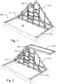
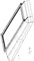
- the inventive method of providing a window arrangement will be described with particular reference to Figs 1 to 5 .
- the window arrangement may be installed on any suitable supporting structure, including walls and other façade elements, and is in the embodiment shown in the drawings an upstand generally designated 200 and built into a substantially flat roof structure (not shown).
- the upstand 200 may for instance be formed as a concrete element cast either as a coherent element or assembled by a number of parts to form two longitudinal portions extending in parallel with the direction of the ridge of the window arrangement, and two transverse portions, together framing an opening or clearing 205.
- a beam element 211, 212 is placed on top of each of the longitudinal portions.
- the beam elements 211 and 212 may be formed in any suitable manner, for instance by dimensional lumber 2x4 of softwood, or be a beam of metal or other suitable material, such as for instance an I-beam to be described in further detail in another embodiment.
- a set of gable elements 221 and 222 is provided.
- the gable elements 221 and 222 may be formed as identical parts made up of dimensional wood and define the slope or pitch of the window arrangement.
- the dimensions of each gable element 221, 222 are such that the length corresponds in substance to the length of the transverse portions of the upstand 200 and bridges the distance between the beam elements 211 and 212.
- Each gable element 221, 222 may be provided by abutment means, not shown in detail, protruding from the underside of the gable element into the clearing defined by the opposed beam elements and/or the longitudinal portions of the upstand 200 in order to prevent movement of the gable element in the transverse direction.
- the height is determined by the desired pitch of window arrangement. In the embodiment shown, the pitch is approximately 45° but the pitch may vary.
- the first gable element 221 is fastened to the supporting structure, in the embodiment shown thus to the one transverse portion of the upstand 200 and to the beam elements 211 and 212, for instance by screwing the longitudinal ends of the gable element 221 into the beam elements 211 and 212.
- the second gable element 222 is connected to the beam elements 211 and 212 as well and possibly also to the opposed longitudinal portions of the upstand 200, at a distance from the first gable element 221 corresponding in substance to the width of a window to be used in the window arrangement.
- the windows of the window arrangement need not necessarily all be of the same character or have the same width; for instance one or more windows may be formed as a panel element having a different character.
- all windows 231, 232; 233, 234; and 235, 236 of the window arrangement have a similar structure to be described in detail below.
- the connection between the second gable element 222 and the beam elements 211, 212 and possibly the longitudinal portions of the upstand 200 is releasable, meaning that the connection may be disengaged without substantial damage to either of the elements involved.
- the position shown in Fig. 1 has now been attained.
- a first window 231 of a first pair is mounted to the one side of the juxtaposed gable elements 221, 222. This is carried out by connecting fittings present at the top of the window 231 to the gable elements 221, 222, for instance by brackets (not shown) connected to the apex of each gable element. Embodiments of the fittings at the top of the window will be described in more detail below.
- the window 231 is lifted into place either manually or by means of crane. Subsequently, the window 231 is swung down about the fittings at the top such that the bottom thereof may be connected to the beam element 211. Details of this operation are to be described further on.
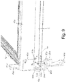
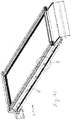
- a second window 232 of the first pair is then lifted into position and the top of the second window 232 is positioned opposite the top of the first window 231.
- the fittings of the second window 232 are connected to those of the first window 231 and the position shown in Fig. 2 has been attained.
- the second window 232 is swung into position and the bottom of this window is fastened to the beam element 212.
- the gable elements 221 and 222 are in principle superfluous for structural reasons, as the windows of the arrangement are self-supporting.
- the first gable element 221 remains connected to the first window 231 by its connection to the bracket at the apex of the gable element 221, but the second gable element 222 is released from its engagement with the first window 231 and from the beam elements 211, 212 and possibly the longitudinal portions of the upstand 200.
- the second gable element 222 is subsequently moved to position spaced apart from the sides of the windows 231, 232 of the first pair opposite the first gable element 221.
- it is re-connected releasably to the beam elements 211 and 212 and possibly the opposite longitudinal portions in the manner described in the above.
- the first window 233 of a second pair of windows of the window arrangement is at its top connected to the fitting of the first window 231 and to the bracket at the apex of the second gable element 222 to attain the position shown in Fig. 3 .
- a second window 234 of the second pair is connected to the first window 233 by its fittings at the top to attain the position of Fig. 4 . Subsequent to the position shown in Fig. 4 , also the bottom of the second window 234 is secured to the beam element 212 on the upstand 200.
- the steps of removing the second gable element 222 from its engagement with the first window and from the beam element 211 is repeated, as is the step of positioning the second gable element 222 at a distance from the sides of the first and second window of the preceding pair of windows of the window arrangement.
- the second gable element 222 has been positioned at the transverse portion 204 opposite the transverse portion at which the first gable element 221 is positioned.
- the second gable element 222 is fastened permanently to the beam elements 211 and 212 and possibly the other transverse portion of the upstand 200.
- the permanent connection may be the same as the temporary connection shown in the position of Figs 1 and 2 , or comprise further fastening means according to needs or specifications.
- Fig. 5 it is shown how the first window 235 of the third and last pair of windows of the window arrangement has already been connected to the first window 233 of the preceding pair, i.e. the second pair, and to the second gable element 222.
- the second window 236 is shown in the situation, in which the top of the second window 236 is connected to the top of the first window 235 and by its bottom to the beam element 212.
- the window arrangement contains a number of pair of self-supporting windows.
- finish is normally provided, in the form endings at the respective gable elements 211 and 212, just as flashings and coverings are provided. Details relating to such aspects will be described below.
- the window comprises a substantially rectangular frame structure generally designated 1; apart from this feature, the design of the window is arbitrary and may for instance take the form of a panel system comprising a frame and sash combination, in which the sash carries a pane and may be opened for ventilation or smoke evacuation purposes, or fixed, that is, not openable relative to the frame structure.
- a non-transparent or partially transparent panel element such as a solar panel.
- the window according to the invention may be used for many different geometrical configurations, e.g. as structural skylights abutting upstands such as an array of long lights forming a light band and ridge constellations.
- structural skylights abutting upstands such as an array of long lights forming a light band and ridge constellations.
- the frame structure 1 has four corner sections 1a, 1b, 1c and 1d and is adapted to be installed in a roof structure (not shown).
- the frame structure 1 is composed by four frame members 2, 3, 4 and 5, extending between respective corner sections; however, the frame structure may also be a coherent structure.
- the window furthermore comprises a bracket arrangement comprising a set of bracket units 6a, 6b, 6c and 6d.
- each bracket unit includes a base element 10a, 10b, 10c and 10d mounted at the respective corner section 1a, 1b, 1c and 1d of the frame structure 1.
- each bracket unit comprises at least one supplemental element adapted to be detachably connected to the base element.
- each bracket unit comprises at least one supplemental element adapted to be detachably connected to the base element.
- the individual configuration of each bracket unit of the embodiment shown will be described in detail further down.
- terms such as “lower”, “upper”, “left-hand”, “right-hand”, “side”, “top”, “bottom”, etc. refer to the shown position of the window only, and is not to be interpreted as limiting the window to use in a particular position.
- a particular use of the window according to the invention is shown, viz. in a window arrangement, for instance to be provided by means of the inventive method.
- Fig. 6 only one window is shown; this window corresponds to the first window 231 of the first set of opposed windows of the embodiment shown in Figs 1 to 5 .
- the other windows are omitted for reasons of clarity, and would correspond to the second window 232 of the first pair and to the first and second windows 233 and 234 of the second pair.
- the bracket unit 6c is shown in a basic condition, i.e. comprising only base element 10c including its engagement means 13c.
- the engagement means 13c are adapted to be connected to the engagement means 113c of a supplemental element constituted by the base element 110d of another, second window positioned opposite to the window shown, to the base element 310d of a third window next to the first window, and to the base element 210c of a fourth window opposite the third and next to the second, thus making interconnection of four windows possible.
- the respective engagement means are complementary to each other.
- each base element could be formed as illustrated in Fig. 7 , and combined with an arbitrary panel element, which needs not necessarily be a window, but could in principle be any panel element, such as a blind panel, a solar panel etc.
- the base element would then be combined with suitable supplemental element(s).
- one such supplemental element comprises, in the embodiment shown, a leg element 20a, 20b, 20c, 20d which in the shown state is connected to the respective base element 10a, 10b, 10c and 10d in a manner which is rotatable and detachable, that is the leg element may be connected and disconnected from the base element by suitable connection means and is able to rotate about an axis of rotation relative to the base element.
- the base element 10a is formed by two substantially plate-shaped parts 11a, 12a such that they together surround the intersection in the corner section 1a and protrude from the frame structure in a plane substantially parallel to that of the frame side member 5.
- the base element 10a could also be formed as a one-part element.
- the leg element 20a is connected to the base element 10a in a hinge connection including a bolt 21a and matching apertures (not shown) in the base element 10a and hinge portion 22a of the leg element 20a.
- the leg element 20a furthermore includes fastening means for connection to the roof structure.
- the fastening means include two portions 24a and 25a formed as folded portions depending from abutment portion 23a and a plurality of apertures in the folded depending portions. This embodiment is particularly useful in installation conditions involving a beam, for instance positioned on an upstand made to that purpose in a roof.
- the base element 10b and the leg element 20b of the bracket unit 6b of the lower right-hand corner are configured in manner corresponding to that of bracket unit 6a.
- the window is shown in a state of storage, in which the window is adapted to be positioned in a stack of similar windows, for instance up to six windows.
- a supplemental element comprising a spacer element 40a and 40b, respectively, is connected to the respective base element 10a and 10b in a detachable manner, for instance by bolts (not described in detail).
- the spacer elements 40a, 40b - together with corresponding spacer elements at the top of the window - provide for the space needed between windows positioned on top of each other and protect the windows by transmitting the weight of the upper window or systems to the lower window or systems via the base elements of the bracket units, without parts of the frame structure or other parts of the window coming into contact with each other.
- Each spacer element has an upper end and a lower end, the upper end 41a and the lower end 42a of the spacer element 40a of the lower left-hand corner section 1a being provided with engagement means, the respective engagement means at the upper end and the lower end being complementary to each other.
- the spacer element 40b at the lower right-hand corner section 1b may have a similar configuration, or as shown, a lower end 42b ending at the base element 10b.
- the spacer elements 40a and 40b are connected to each other by means of a transverse bar member 45a by means of suitable fittings 46a, 46b.
- Fig. 11 showing the lower right-hand corner of the window, the window is shown in a state of delivery, in which the spacer elements 40a and 40b have be detached from the respective base element 10a and 10b.
- Another supplemental element connected detachably to the base element 10b is shown in this Figure, namely a lifting element 50b.
- bracket units 6a, 6b at the bottom part of the window are substantially identical, and the bracket units 6c, 6d at the top correspond to each other but slightly are different from bracket units 6a, 6b at the bottom part.
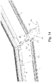
- Figs 12-14 and 6-7 the top part of an embodiment of the window will be described in detail.
- the base element 10c comprises two plate-shaped parts 11c, 12c and is connected to a leg element 20c.
- the leg element 20c is connected to the base element 10c by means of an adaptor element 60c.
- the adaptor element 60c is provided with engagement means 61c complementary to engagement means 13c of the base element 10c. Additional fastening may be provided, for instance in the form of detachable bolts 62c and 62d.
- the leg element 20c is provided with a hinge portion 22c hingedly and detachably connected to the adaptor element 60c by a bolt 31c and is provided with fastening means in the form of abutment portion 23c and a number of suitable apertures.
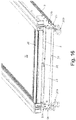
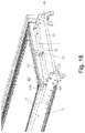
- bracket units 6c, 6d at the top are provided with spacer elements 40c, 40d at each end of transverse bar 45c.
- FIG. 13 showing the window in a state of delivery
- the spacer elements 40c, 40d and transverse bar 45c have been removed, and lifting elements 50c, 50d are visible.
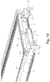
- the lifting element 50c and the remaining lifting elements are removed thus attaining the state in Fig. 8 , in which the window is ready to be fastened to the underlying roof structure and reach its built-in position of use.
- the leg elements 20a-20d are adjusted relative to the base elements 10a-10d to accommodate inclination, tolerances etc.
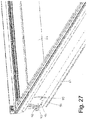
- Figs 15 to 27 an embodiment with particular focus on the operator and the hinge connection will be described in further detail.
- the reference numerals of this embodiment are the same for denoting elements having the same or analogous function.
- a frame structure 1 of the window according to the invention has four corner sections 1a, 1b, 1c and 1d and is adapted to be installed in a roof structure (not shown).
- the frame structure 1 is composed by four frame members 2, 3, 4 and 5, extending between respective corner sections.
- the window furthermore comprises a bracket arrangement comprising a set of bracket units 6a, 6b, 6c and 6d.
- each bracket unit includes a base element 10a, 10b (only shown at the bottom of the window in the embodiment shown - base element 10d of the upper left-hand corner visible in Fig. 26 ) mounted at the respective corner section 1a, 1b, 1c and 1d of the frame structure 1.
- each bracket unit comprises at least one supplemental element adapted to be detachably connected to the base element.
- each bracket unit of the embodiment shown will be described in some detail further down.
- terms such as “lower”, “upper”, “left-hand”, “right-hand”, “side”, “top”, “bottom”, etc. refer to the shown position of the window only, and is not to be interpreted as limiting the window to use in a particular position only.
- the bracket units may be provided with a number of supplemental elements.
- One such supplemental element may for instance, as shown at the bottom only of the window in the embodiment shown, comprise a leg element 20a, 20b which in the shown state is connected to the respective base element 10a, 10b in a manner which is rotatable and detachable, that is, the leg element may be connected and disconnected from the base element by suitable connection means and is able to rotate about an axis of rotation relative to the base element.
- supplemental elements include an adaptor element, a spacer element and a lifting element. The window is fastened to the supporting structure by means of the bracket arrangement, which thus transfers the load resulting from the weight of the window to the roof supporting structure.
- the window furthermore comprises a sash structure carrying a pane element 21 and including a plurality of sash members 12, 13, 14, 15, and an operator 31 including an operator member 32 having a first and a second end and adapted to extend between the frame structure and the sash structure.
- the operator 31 is mounted on the external side of a first frame member constituted by the bottom frame member 2.
- the operator in the embodiment shown is a chain operator and the operator member 32 is thus a chain which is able to transfer pressure and tension during opening and closing, respectively, of the sash structure relative to the frame structure.
- the term “external” is used for surfaces facing away from the opening defined by the window frame, while the terms “outer” and “inner” is used to indicate that a surface faces the outside or inside of the building, respectively.
- the operator 31 is connected to the bracket arrangement of the window, namely to the bracket units 6a and 6b at the bottom of the window.
- This makes it possible to transfer the load resulting from the weight of the sash, friction in hinges etc., directly to the bracket arrangement and further out to the supporting structure, without any load being absorbed by the frame itself.
- This increases the degree of freedom in designing the frame structure.
- the operator in the embodiment shown is accommodated in a housing 33 extending substantially between two adjacent bracket units 6a, 6b of the bracket arrangement.
- the housing is rotatably and detachably connected to the bracket units 6a, 6b in any suitable manner, for instance by a hinge pin connected to the base element of each bracket unit. This allows for the operator to follow the movement of the sash when opening the sash relative to the frame.
- a first end of the operator member 32 is accommodated in the operator itself and a second end of the operator member is connected to a transverse element 41 extending between sash members adjacent to the sash member opposite the first frame member, i.e. in the embodiment shown to the sash member 15 and 13 adjacent the bottom sash member 12.
- a transverse element 41 extending between sash members adjacent to the sash member opposite the first frame member, i.e. in the embodiment shown to the sash member 15 and 13 adjacent the bottom sash member 12.
- the transverse element 41 is arranged to extend externally of the pane element 21 of the sash structure, and in a mechanically simple further development, the transverse element 41 is fastened to the sash members adjacent to the sash member opposite the first frame member by means of a fitting 41a (only the left-hand fitting visible in Figs 18 and 19 ).
- the operator forms a contained unit positioned externally and is as such hidden from the inside.
- the operator may in the installed position of the window be at least partly concealed under cover plate 35 and a flashing arrangement 72 mounted on the frame structure 1, i.a. by means of a connector element 71.
- the flashing arrangement and the connector element are described in further detail in another embodiment.
- the operator is a chain operator and the operator member a chain. This provides for a particularly compact design, but other kinds of operators are conceivable as well, such as a scissors operator and a pressure medium operated opener/closer.
- the window according to the invention may be used for many different geometrical configurations, e.g. an array of long lights forming a light band and ridges.
- FIG. 25 One conceivable installation situation is shown in Fig. 25 , in which two windows according to the invention are built-in side-by-side.
- the left-hand window may be as described in the above, thus showing the right-hand frame member 3, the right-hand sash member 13 and the pane element 21.
- To the right of the window there is a further window, of which the left-hand frame member 105 and sash member 115 are shown.
- the sash member 115 carries the pane element 121 together with other sash members.
- a drain element 51, 151 is positioned in connection with the respective frame member 3, 105 such that they form two drain grooves positioned side-by-side.
- a common cover element 61 spans the gap between the adjacent sash members 13 and 115 and extends somewhat into the border portion of the respective pane element 21, 121.
- the members of the frame and sash structures may in principle be formed in any suitable manner, but may preferably be formed as thin-walled profiles, such as fibre glass reinforced profiles made by pultrusion. Details of such profiles and in particular the fastening of the pane elements 21, 121 by means of glazing lists are described in further detail in other embodiments.
- the hinge connection between the sash structure and the frame structure may in principle be formed in any suitable manner to provide a hinge axis at the top of the window or at another location between the top and bottom, or between the sides.
- a hinge axis located at the top of the window is preferred.
- the hinge connection may for instance include a hinge pin connected with the sash structure and a journal connected with the frame structure.
- one possible design is by accommodating the connection between the sash structure and the frame structure within the bracket arrangement. This is shown in detail in Figs 26 and 27 .
- a first hinge part 91 is connected to the sash structure and a second hinge part 81 is connected to the bracket arrangement, i.e. in the embodiment shown to the bracket units 6c and 6d at the top of the window.
- the second hinge part 81 comprises a first guidance 82 formed as an arc-shaped recess and a second guidance 83 formed as an arc-shaped track in a plate-shaped element 84.
- the plate-shaped element 84 of the second hinge part 81 is connected to the bracket unit 6d in that a folded portion 85 of the second hinge part 81 is connected to the base element 10d of the bracket unit 6d.
- the folded portion 85 may either be formed integrally with the plate-shaped element 84 or connected in any suitable manner, for instance by means of rivets or screws.
- the first hinge part 91 includes a first arc-shaped arm 92 for cooperation with the first guidance 82 of the second hinge part 81.
- a further connection between the first and second hinge parts is provided by a stop pin 93 which in the mounted position cooperates with track 83.
- the arm 92 and the stop pin 93 are formed on a plate-shaped element 94 connected to the sash side member 15 by means of suitable fastening means 95 which may be screws or rivets.
- Figs 28 to 31 embodiments focusing on the internal cover of the window arrangement according to the invention are described.
- Fig. 28 the two windows 231 and 232 of the first set of opposed windows in the window arrangement of the embodiment of Figs 1 to 5 are shown.
- the bracket unit 6c is shown in a basic condition, i.e. comprising only base element 10c including its engagement means 13c.
- the engagement means 13c are adapted to be connected to the engagement means 113c of a supplemental element constituted by the base element 110d of the second window 232 positioned opposite to the first window 231.
- An internal cover device generally designated 300 extends longitudinally in the shown embodiment of the window arrangement according to the invention.
- the cover device 300 comprises a profile 301 made of e.g. aluminium to which a strip 302 of an insulating material is adhered.
- the profile 301 has a track 303 formed near its apex and is fastened to the opposed windows 231 and 232 by means of a bolt 304 with nut 305, washer 306 and clamping disc 307.
- the bolt 304 is inserted into the track 303, for instance from one of the ends of profile 301, and is inserted into a gap provided by opposed flanges 20 and 120 fastened to a respective window 231 and 232.
- the washer 306 and nut 305 are subsequently brought into engagement with the bolt 304.
- a plurality of bolts may be provided at suitable intervals along the length of the profile 301.
- the cover device 300 may extend substantially throughout the length of the window arrangement, or a number of shorter cover devices may be utilised.
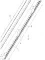
- Figs 30 and 31 another feature of the covering device 300 is illustrated, viz. that it may accommodate pitches within a large angle interval.
- a frame 1 of a window which may for instance be one of the windows 231-236 of the window arrangement of Figs 1 to 5 , is resting on an upstand 400 on a roof surface (not shown).
- the frame 1 is connected to the surrounding roof structure, i.e. the upstand 400, by means of a bracket unit 61 connected to a leg element 420a.
- a bracket unit 61 connected to a leg element 420a.
- an I-beam 401 with an upper flange 402, a web 403 and a lower flange 404 is mounted in any suitable manner.
- the bracket unit 6c is shown as having a pivot joint to the leg element 420a, but other types of bracket units may of course also be employed.
- the leg element 420a is connected to the I-beam 401 by means of a clamping device comprising two parts 421 and 422 clamping the leg element 420a to the I-beam 401 by engagement with the upper flange 402 of the I-beam 401. Furthermore, an insulating portion 410 of the upstand 400 is indicated, just as a barrier element 430 extending from a flange 150 connected to the frame 1 to the lower flange 404 of the I-beam 401.
- Fig. 33 shows an alternative to the above embodiment, in that the upstand 400 with an insulating portion 410 is covered by a layer 440 of a roofing material such as a bituminous felt.
- the barrier element 430 extends from the flange 150 connected to the frame 1 to the layer 440.
- the I-beam is replaced with another type of beam element 450 connected to the upstand 400 in a suitable manner (not shown).
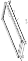
- FIGs 34a and 34b an embodiment of a detail of a further aspect of the invention is shown in Figs 34a and 34b .
- the load on the window arrangement resulting not only from the weight of the windows, but in particular the wind load, may be so substantial that it is not desirable to make use of solely the self-supporting feature provided by two opposed windows.
- a separate rafter or truss element 500 as shown in Fig. 34a may be utilised between adjacent sets or pairs of windows.
- the rafter element 500 may for instance be made as a welded hollow profile of a suitable material, for instance steel.
- a foot flange 501 with two protruding flanges 502 is provided at each end of the longitudinal ends of the rafter element 500.
- the foot flanges 501 and its protruding flanges 502 are adapted to abut on the upstand and/or a beam element on the supporting structure and secure that the rafter element 500 does not tilt during installation.
- Fastening of the rafter element 500 to the upstand and/or beam element may be carried out by inserting screws through openings (not shown in detail) in the protruding flanges.
- a foot flange 505 is provided with stepped portions 506 on either side to be positioned on the upstand and fixed by means of clamping members 507.
- a gutter-like recess 503 is formed for abutment of the respective top of windows positioned opposite each other and next to each other.
- the gutter-like recess 503 may be provided with engagement and centering means, for instance in the form of protruding pegs (not shown) to cooperate with the windows.
- a rafter element 500 may be positioned between each neighbouring pairs of windows, or rafter elements may be positioned only between selected pairs of windows.
- One alternative method of installing a window arrangement comprises the steps of providing a support structure and then mount a number of rafter elements, to which the windows are connected. This method is however not part of the claimed invention.
- a mounting beam device is used instead of the movable gable element. This method is however also not part of the claimed invention.
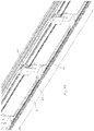
- an array of neighbouring windows is provided to form a longlight configuration.
- Each window is provided with a plurality of predefined connection points.
- the predefined connection points include the bracket units and a number of connection points along the length of the side frame members.
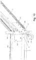
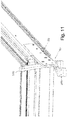
- connection brackets As shown in Figs. 36-38, Figs. 36 and 38 showing the detail A in Fig. 35 .
- the sets of connection brackets are positioned in the connection points distributed evenly along the length of the side frame members.
- Each set of connection brackets include a pair of first parts to be attached to the frame and a second part to be connected to each of the first parts of said pair.
- each set of connection brackets includes, in the embodiment shown, two female parts 601 attached one to the frame of each of the windows, in the embodiment shown in a recess 600 in the side frame member, and a male part 602.
- the male part is U-shaped with two legs projecting downwards on the drawing.
- connection points may not be reached or only reached with difficulty for mounting of the male parts.
- a ladder 700 may be placed as shown in Fig. 39 , following which the male parts located far from the bottom (for instance as indicated by detail A) may easily be reached.
- One or both of the legs of the male part are preferably provided with projections adapted to lock into matching recesses in one or both the female parts.
- the male part and/or female parts may be made at least partially resilient so that it may yield and then snap into engagement with the other part. This is preferably achieved by making the connection brackets from an elastic material and with weakening zones concentrating the bend to predetermined areas of the bracket.
- the male part is relatively weak at the part interconnecting the legs, meaning that when legs of the male part are forced into the openings in the female parts, the legs are forced apart deforming the interconnecting part.
- the openings in the female parts are downwards open passages, which are and somewhat shorter than the legs of the male part, and the legs of the male part have slight inwards bends at their distal ends. These distal ends come to project through the lowermost opening of the passage in the female part and the bends contributes to keeping the male part in place once mounted.
- Preferred materials providing the needed elasticity include plastics, such as polyethylene, and metals, such as aluminium, but composites may also be used.
- connection brackets The number of sets of connection brackets to be used depends on the size of the window, but it is preferred to use at least two.
- the window in Fig. 35 is provided with five female parts distributed substantially evenly along the length of the side member of the window frame.
- the female parts are preferably attached to the window in the state of delivery, but may also be attached to the window at the installation site.
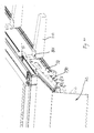
- Figs. 40-44 the windows generally designated 1 mounted at the end of a row of windows are provided with flashing members, cover members 900 and cover brackets 801 adapted for attachment thereof.
- the flashing used at the bottom is in one piece and will not be described in further detail, whereas two flashing members are used along the side of the window. This keeps the sizes of the flashing members relatively uniform and makes them relatively easy to handle, transport and store.
- Cover members between neighbouring windows are formed in a slightly different member than the cover member 900 at the end, but will not be described in further detail. Common to all cover members is that they provide for a weathertight transition between the pane and other parts of the windows.
- the cover brackets 801 are attached to the side member 5 of the frame of the window 1 on top of the pre-mounted female connection brackets 601, which are not to be used, since this side of the window is not to be interconnected with another window.
- the female connection brackets may advantageously contribute to the attachment of the cover brackets, though this is not the case with the embodiment shown.
- the cover bracket 801 comprises a number of portions extending from a main portion 806.
- a lower flange 802 of the cover bracket 801 projects into a groove 800 in the frame side member 5 otherwise used for holding a sealing strip.
- This mode of attachment provides for a good resistance against rotation of the bracket, which is particularly important, when heavy winds affect the cover members.
- the need for screws penetrating the frame side member for attachment of the brackets is reduced, which is a particular advantage when using frame members made from fibre glass reinforced plastic.
- all windows are made identical and that the sealing strip is then removed at the site of installation on those windows, which are to be used at the ends. It is, however, also possible to provide some windows without sealing strips or with interruptions of the sealing. Other alternatives includes to use cover brackets without the flange or to provide special windows with different side members than the standard window and/or pre-mounted cover brackets for use at the ends.
- a flange 803 projecting outwards perpendicularly to the side member 5 of the frame is intended for interconnection with battens 799 or insulating members used on top of the upstand (cf. Fig. 48 ).
- the cover bracket 801 has an off-set section 804, which is used for attachment of the cover members, the cover members having a vertical section, which is later covered by the covering shown in Fig. 42 .
- the section being off-set means that a gap is formed between the cover and the frame side member. This gap may be left open, filled with insulating material or used for technical installations such as wiring for solar cells or the like.
- a flange 805 serves as an abutment and fixing means for covering 900.
- the left-hand window may be as described in the above, thus showing the right-hand frame member 3, the right-hand sash member 13 and the pane element 21.
- To the right of the window there is a further window, of which the left-hand frame member 105 and sash member 115 are shown.
- the sash member 115 carries the pane element 121 together with other sash members.
- the connection bracket 601 is shown as well.
- a common cover element 61 spans the gap between the adjacent sash members 13 and 115 and extends somewhat into the border portion of the respective pane element 21, 121.
- a sealing 620 is mounted in the lower portion of the frame members 3, 105.
- a bottom flashing member 72 is attached by means of a connector bracket 79 riding on mounting bracket 711.
- the connector bracket has a substantially H-shaped cross-sectional shape, with the two lower legs extending on each side of the mounting bracket and the two upper legs forming a gutter 791. It is, however, to be understood that a connector bracket does not need to ride on the mounting bracket but may also be attached directly to the window frame.
- the second leg 722 of the flashing member 72 has a bent end edge 727, which engages a longitudinal edge of the gutter 791 formed in the upper surface of the connector bracket 79. This engagement keeps the flashing member 72 from moving away from the connector bracket 79 in the horizontal direction and at the centre of the gutter is a raised part 793, which prevents it from moving in the opposite direction.
- the gutter is open-ended at the end of the connector bracket, which is furthest from the window, to allow it to be used for drainage purposes as will be explained below, but if this is not the case, the flashing member will also be kept from moving away from the window.
- the first leg 721 of the flashing member 72 is located underneath a projection 792 on the connector bracket 79 having the shape of an inverted J, which projects upwards.
- the height of the body of the J corresponds substantially to the height of the first leg 721, so that the upper edge of the first leg lies at the inner corner of the J, where the arm and body meets, the first leg abutting the body of the J.
- the first leg 721 has a bent edge 728 as is common to this kind of flashing members and the arm of the J corresponds in size and shape to this bend edge.
- the projection 792 may be elastic so that is can be bend slightly to ease the introduction of the flashing member 72.
- the engagement between the flashing member 72 and the projection 792 prevents the flashing member from moving in the vertical direction and combined with the engagement between the bent end edge 727 and the gutter 791 the flashing member is thus fixated.
- a further optimisation may be achieved by using the projection 792 to support covering and cladding members (not shown), including those used at the side of the window.
- a connector bracket 790 without projection may, however, also be used, an example of which is shown in Figs 47 and 48 , where like elements have been given the same reference numbers as in Fig. 46 .
- This connector bracket is further provided with a pair of walls 797 extending in the length direction of the gutter 791 and dividing it in three. These walls are intended as an alternative to the raised part 793 and have the advantage that the screw will get a good hold even if displaced along the length of the gutter. They may also serve as guides or abutments for the flashing members.
- Figs 47 and 48 shows only a single flashing member 72, but it is to be understood that a second flashing member, such as the bottom flashing member of a neighbouring window, could be placed with a bent end edge engaging the opposite longitudinal edge of the gutter 791.
- the gutter is of a rectangular shape, when seen from above. This also contributes to a narrow joint, which is advantageous both with regards to tightness and aesthetics. If, however, an angle is desired between neighbouring flashing members, this may be achieved by providing the longitudinal gutter edges at an angle to each other.
- the connector brackets 79, 790 in Figs 46-48 rest on the mounting bracket 711 used for interconnecting the window to the roof structure.
- the mounting bracket shown is substantially flush with the external side of the side member of the window frame, which means that when mounting two windows side by side their mounting brackets will lie closely along each other.
- the space C between its two walls should be somewhat larger than twice the thickness of the body of the mounting bracket.
- This centred position of the connector bracket 79, 790 entails that the joint between neighbouring flashing members will also be centred which will lead to an aesthetical advantage, but it is of course also possible to provide a connector bracket at each mounting bracket. In that case a separate member will be needed for covering the space or joint between the two connector members of neighbouring windows, but this may be done by means of an extra-wide version of the covering member used for covering the gutter as described above.
- the flashing members may be provided with flanges on their inner side adapted for engagement with the gutter and have end sections projecting over the flanges to reach the neighbouring flashing member and possibly overlap it.
- windows are often provided with a drainage channel (not shown) at the side members of the window frame for the purpose of collecting condensation as well as any water that might penetrate the system of cladding and covering members.
- the centred position of the connector bracket 79, 790 allows it to be used for draining water collected by such drainage channels and possibly even for receiving water from covering members.
- the connector bracket 79, 790 When the connector bracket 79, 790 has a hollow design as shown in Figs 46 to 48 , it may be filled wholly or partially with an insulating material to minimize the risk of the connector bracket forming an undesirable thermal bridge. In the state of delivery the connector bracket may be filled substantially entirely with insulating material, which can then be removed wholly or partially to make room for mounting brackets or other means of attachment.
Landscapes
- Engineering & Computer Science (AREA)
- Architecture (AREA)
- Civil Engineering (AREA)
- Structural Engineering (AREA)
- Physics & Mathematics (AREA)
- Electromagnetism (AREA)
- Wing Frames And Configurations (AREA)
- Cage And Drive Apparatuses For Elevators (AREA)
- Patch Boards (AREA)
- Securing Of Glass Panes Or The Like (AREA)
Claims (9)
- Procédé d'installation d'un agencement de fenêtres comprenant un certain nombre de fenêtres voisines (231, 232, 233, 234, 235 et 236), comprenant les étapes dei) fourniture d'une structure de support,ii) fourniture d'un premier élément de pignon (221) d'un ensemble d'éléments de pignon,iii) montage du premier élément de pignon (221) sur la structure de support,iv) fourniture d'un second élément de pignon (222) dudit ensemble,v) raccordement temporaire et libérable du second élément de pignon (222) à la structure de support à une distance du premier élément de pignon (221) correspondant sensiblement à la largeur d'une fenêtre,vi) fourniture d'une première fenêtre (231) d'un premier ensemble de fenêtres opposées avec une pluralité de points de raccordement prédéfinis,vii) raccordement de la première fenêtre (231) aux premier et second éléments de pignon (221, 222) et à la structure de support,viii) fourniture d'une seconde fenêtre (232) dudit premier ensemble de fenêtres opposées avec une pluralité de points de raccordement prédéfinis correspondant à des points de raccordement prédéfinis de ladite première fenêtre (231),ix) mise en place de ladite seconde fenêtre (232) près de ladite première fenêtre (231),x) raccordement de ladite première fenêtre (231) à ladite seconde fenêtre (232) au niveau des points de raccordement prédéfinis correspondants,xi) libération du second élément de pignon (222) de la première fenêtre (231) et de la structure de support,xii) raccordement temporaire et libérable du second élément de pignon (222) à la structure de support à une distance du premier ensemble de fenêtres opposées correspondant sensiblement à la largeur d'une fenêtre,
moyennant quoi les étapes vi) à xii) sont répétées un nombre de fois correspondant au nombre prédéfini d'ensembles de fenêtres opposées, à l'exception de l'étape xiii) dans laquelle le second élément de pignon (222) est raccordé de façon permanente aux fenêtres du dernier ensemble,
le procédé comprenant en outre l'étape de :xiii) raccordement des fenêtres d'ensembles voisins de fenêtres opposées les unes aux autres dans des points de raccordement,xiv) raccordement des fenêtres du premier ensemble de fenêtres opposées au premier élément de pignon (221) dans des points de raccordement et raccordement des fenêtres du dernier ensemble de fenêtres opposées au second élément de pignon (222) dans des points de raccordement. - Procédé selon la revendication 1, comprenant l'étape supplémentaire de fourniture d'éléments de couverture (61) et d'éléments de solin (72).
- Procédé selon la revendication 2, comprenant l'étape de fourniture, à chaque organe de cadre latéral d'une fenêtre donnée non en regard de l'organe de cadre latéral d'une fenêtre voisine, d'une pluralité de consoles de couverture (801).
- Procédé selon la revendication 3, dans lequel lesdites consoles de couverture (801) sont situées au niveau desdits points de raccordement prédéfinis.
- Agencement de fenêtres résultant du procédé de la revendication 1, comprenant un certain nombre de fenêtres (231, 232, 233, 234, 235 et 236), comprenant chacune une pluralité de points de raccordement, dans lequel au moins certains desdits points de raccordement sont fournis au niveau desdits organes de cadre latéral, et dans lequel des fenêtres voisines sont raccordées dans lesdits points de raccordement, dans lequel chaque extrémité de l'agencement de fenêtres est formée par les éléments de pignon laissés en place, et dans lequel chaque organe de cadre latéral est pourvu d'au moins trois points de raccordement répartis uniformément suivant la longueur de l'organe de cadre latéral.
- Agencement de fenêtres selon la revendication 5, dans lequel un ensemble de consoles de raccordement (601) est fixé à chaque cadre de fenêtre au niveau au moins de certains desdits points de raccordement, et dans lequel chaque ensemble de consoles de raccordement (601) comporte une paire de premières parties à fixer à chaque cadre de fenêtre et une seconde partie à raccorder à chacune des premières parties de ladite paire.
- Agencement de fenêtres selon l'une quelconque des revendications 5 ou 6, comprenant en outre une pluralité de consoles de couverture (801) fixées auxdits organes de cadre latéral non en regard de l'organe de cadre latéral d'une fenêtre voisine.
- Agencement de fenêtres selon la revendication 7, dans lequel lesdites consoles de couverture (801) sont situées au niveau desdits points de raccordement prédéfinis.
- Agencement de fenêtres selon la revendication 8, dans lequel lesdites consoles de couverture (801) sont montées au niveau de points de raccordement prédéfinis déjà pourvus d'une première partie d'un ensemble de consoles de raccordement (801).
Priority Applications (2)
| Application Number | Priority Date | Filing Date | Title |
|---|---|---|---|
| PL11195792T PL2472028T3 (pl) | 2010-12-29 | 2011-12-27 | Sposób instalowania układu okien zawierającego pewną liczbę sąsiednich okien, oraz taki układ okien |
| EP11195792.4A EP2472028B1 (fr) | 2010-12-29 | 2011-12-27 | Procédé d'installation d'un agencement de fenêtre comportant plusieurs fenêtres voisines et une telle organisation de fenêtres |
Applications Claiming Priority (4)
| Application Number | Priority Date | Filing Date | Title |
|---|---|---|---|
| EP10197235.4A EP2472024B1 (fr) | 2010-12-29 | 2010-12-29 | Fenêtre dotée d'un moyen de montage souple |
| DKPA201170359A DK179130B1 (en) | 2011-07-04 | 2011-07-04 | Method of providing a window arrangement, a window arrangement comprising a set of gable elements and a number of opposed windows, and window of such a window arrangement |
| DKPA201170590 | 2011-10-31 | ||
| EP11195792.4A EP2472028B1 (fr) | 2010-12-29 | 2011-12-27 | Procédé d'installation d'un agencement de fenêtre comportant plusieurs fenêtres voisines et une telle organisation de fenêtres |
Publications (3)
| Publication Number | Publication Date |
|---|---|
| EP2472028A2 EP2472028A2 (fr) | 2012-07-04 |
| EP2472028A3 EP2472028A3 (fr) | 2015-12-02 |
| EP2472028B1 true EP2472028B1 (fr) | 2017-12-13 |
Family
ID=45373691
Family Applications (1)
| Application Number | Title | Priority Date | Filing Date |
|---|---|---|---|
| EP11195792.4A Active EP2472028B1 (fr) | 2010-12-29 | 2011-12-27 | Procédé d'installation d'un agencement de fenêtre comportant plusieurs fenêtres voisines et une telle organisation de fenêtres |
Country Status (4)
| Country | Link |
|---|---|
| US (2) | US8720134B2 (fr) |
| EP (1) | EP2472028B1 (fr) |
| CN (1) | CN102535716B (fr) |
| PL (1) | PL2472028T3 (fr) |
Cited By (1)
| Publication number | Priority date | Publication date | Assignee | Title |
|---|---|---|---|---|
| EP3636849A1 (fr) * | 2018-10-12 | 2020-04-15 | VKR Holding A/S | Procédé permettant de recouvrir un espace entre des fenêtres au niveau du faîtage d'un trou de lumière à pente double, trou de lumière à pente double et élément de couverture à utiliser en son sein |
Families Citing this family (10)
| Publication number | Priority date | Publication date | Assignee | Title |
|---|---|---|---|---|
| GB2512938A (en) * | 2013-04-12 | 2014-10-15 | Ultraframe Uk Ltd | Roof structure |
| US8839577B1 (en) * | 2013-04-15 | 2014-09-23 | Roy C. Wildeman | Skylight window dormer |
| DK178524B1 (en) | 2013-06-21 | 2016-05-23 | Vkr Holding As | A window arrangement comprising a plurality of window systems and at least one accessory element |
| JP6222473B2 (ja) * | 2014-08-29 | 2017-11-01 | 京セラドキュメントソリューションズ株式会社 | 画像読取装置及び該画像読取装置を備えた画像形成装置 |
| US10041163B1 (en) | 2017-02-03 | 2018-08-07 | Ge-Hitachi Nuclear Energy Americas Llc | Plasma spray coating for sealing a defect area in a workpiece |
| US11255090B2 (en) * | 2019-01-10 | 2022-02-22 | Vkr Holding A/S | Connector bracket for interconnecting roof windows, a roof window arrangement, and a method for mounting at least two windows in an inclined roof structure |
| US11002016B2 (en) * | 2019-01-10 | 2021-05-11 | Vkr Holding A/S | Connector element for a flashing assembly for use in a roof window arrangement, and a method for weather proofing a roof window arrangement |
| WO2021120780A1 (fr) * | 2019-12-20 | 2021-06-24 | 四川麦克威通风设备有限公司 | Cadre interne pour imperméabilisation de porte/ fenêtre, porte/ fenêtre le comprenant et son procédé de fabrication |
| DK202000081U4 (da) | 2020-08-26 | 2021-12-02 | Vkr Holding As | Et forbindelsesbeslag til ved forbinde et inddækningselement og et beklædningselement til en vindueskarm og et tagvindue omfattende sådan et forbindelsesbeslag. |
| CN113684978B (zh) * | 2021-08-26 | 2023-03-14 | 山东盛阳工程机械有限公司 | 一种顶部斜度可调的钢结构厂房 |
Citations (1)
| Publication number | Priority date | Publication date | Assignee | Title |
|---|---|---|---|---|
| US20060000161A1 (en) * | 2004-06-03 | 2006-01-05 | Vkr Holding A/S | Modular skylight frame and system |
Family Cites Families (43)
| Publication number | Priority date | Publication date | Assignee | Title |
|---|---|---|---|---|
| US1921303A (en) * | 1931-12-07 | 1933-08-08 | Super Steel Products Company | Skylight |
| GB461238A (en) | 1935-06-12 | 1937-02-12 | Marcus Dodds Thompson Lamb | Improvements in or relating to collapsible buildings |
| US2175653A (en) * | 1937-08-11 | 1939-10-10 | Williams Jack | Glass-supporting metallic frame |
| DK82857C (da) | 1955-01-21 | 1957-05-27 | Rasmussen & Co V K | Anordning ved inddækninger for skråtliggende ovenlysvinduer og kappeemne til anvendelse ved disse inddækninger. |
| US3158961A (en) * | 1961-05-19 | 1964-12-01 | Super Sky Products Inc | Adjustable glazing system |
| DE3206871C1 (de) | 1982-02-26 | 1983-06-01 | Velux GmbH - Bauzubehör, 2000 Hamburg | Kombinations-Eindeckrahmen fuer nebeneinander einzubauende Dachfenster |
| DE3602026A1 (de) | 1986-01-24 | 1987-07-30 | Peter Schwarz | Vorrichtung fuer das setzen von fenster- oder tuerstoecken od.dgl. offenen oder geschlossenen rahmen |
| DE3642464A1 (de) | 1986-12-12 | 1988-07-28 | Rasmussen Kann Ind As | Befestigungsanordnung und -verfahren fuer dachflaechenfenster |
| BE1000350A5 (fr) * | 1987-02-27 | 1988-11-08 | Saint Roch Glaceries | Panneau vitre cintre. |
| US5161345A (en) * | 1990-12-03 | 1992-11-10 | Sobjack Sr Ernest J | Method and apparatus for supporting and erecting trusses and other building frame assemblies |
| NZ259493A (en) * | 1993-12-20 | 1997-10-24 | R A R Consultants Ltd | A building panel has members connected together to form a stressed frame, with a castable substance in the interior of the panel |
| EP0692640A3 (fr) | 1994-06-14 | 1997-07-30 | Rasmussen Kann Ind As | Dispositif actionné par un fluide sous, pression pour l'ouverture et la fermature d'une lucarne ou d'une trappe |
| LT4056B (en) * | 1994-09-13 | 1996-11-25 | Edvardas Satkevicius | Building and working method in constructing of it, roof, window and opening method of it |
| US5797225A (en) * | 1995-01-23 | 1998-08-25 | Ykk Corporation Of America | Sloped roof and head |
| US5568707A (en) * | 1995-01-23 | 1996-10-29 | Ykk Corporation Of America | Solarium structure |
| JPH112007A (ja) * | 1997-06-10 | 1999-01-06 | Sekisui Chem Co Ltd | 天窓構造 |
| DK173494B1 (da) | 1997-11-10 | 2001-01-02 | Velux Ind As | Sæt af elementer og fremgangsmåde ved brug af sættet til inddækning af et taggennembrydende element |
| DK173664B1 (da) | 1997-12-19 | 2001-05-28 | Vkr Holding As | Vindue til montering i en tagkonstruktion samt monteringsbeslag til brug ved monteringen |
| JP3375897B2 (ja) * | 1998-09-22 | 2003-02-10 | 新日軽株式会社 | オーニング装置 |
| US6192643B1 (en) * | 1999-01-14 | 2001-02-27 | Yigel Zadok | Modular pool enclosure system having aesthetic appeal |
| CN1164847C (zh) * | 1999-04-23 | 2004-09-01 | Vkr控股有限公司 | 一种用于板的安装铰接配装件以及一种包括该配装件的板装置 |
| DK199900556A (da) | 1999-04-23 | 2000-10-24 | Velux Ind As | Panelsystem |
| US6079167A (en) * | 1999-10-04 | 2000-06-27 | Voegele, Jr.; William P. | Continuous ridge skylight system |
| US6629391B1 (en) | 2000-07-06 | 2003-10-07 | Vkr Holding A/S | Window for installation in a roof and a mounting bracket for use in the installation of roof penetrating structures |
| AT410694B (de) | 2000-10-10 | 2003-06-25 | Fuchs Dietrich Anton | Befestigungsvorrichtung, insbesondere maueranker |
| DE10126395C1 (de) | 2001-05-31 | 2003-01-23 | Isoco Kunststofftechnik Gmbh & | Licht-, Lüftungs- und Rauchabzugkuppel |
| US7246469B2 (en) * | 2002-12-16 | 2007-07-24 | Park Lane Conservatories Ltd. | Multi-piece eaves beam for preassembled glazed roof system |
| US7296388B2 (en) * | 2003-08-12 | 2007-11-20 | Valentz Arthur J | Skylight having a molded plastic frame |
| US7392623B2 (en) * | 2004-02-03 | 2008-07-01 | Park Lane Conservatories Ltd. | Eaves beam with framing |
| US7331146B1 (en) | 2004-06-29 | 2008-02-19 | B3 Products, Inc. | Window and door jamb adjustment system |
| US20070000188A1 (en) * | 2005-06-30 | 2007-01-04 | Aleksandr Smushkovich | Wind, hurricane, and cold protection devices |
| US8353131B2 (en) * | 2006-01-12 | 2013-01-15 | Freet Patrick A | Loq-kit building component system |
| NL1031549C2 (nl) | 2006-04-10 | 2007-07-10 | Ubbink Bv | Dakraamsamenstel. |
| US7481028B2 (en) * | 2006-07-17 | 2009-01-27 | Anderson Corporation | Mulling and sealing system for compound fenestration units |
| US8001732B2 (en) * | 2007-04-09 | 2011-08-23 | Michael Regan | Hypershelter |
| DE202007016886U1 (de) * | 2007-12-03 | 2008-02-14 | Bánk, Stefan | Kleinhaus aus Fertigbauteilen |
| PL2231979T3 (pl) | 2007-12-19 | 2017-07-31 | Vkr Holding A/S | Urządzenie łączące |
| US8020350B2 (en) * | 2008-07-21 | 2011-09-20 | Vkr Holding A/S | Seamless deck-sealing surround for skylights and roof windows |
| US7882664B2 (en) * | 2008-07-21 | 2011-02-08 | Vkr Holding A/S | Deck-mounted skylight having unitary cladding component |
| US8191317B2 (en) * | 2008-07-25 | 2012-06-05 | Vkr Holding A/S | Ventilated curb-mount skylight with separable hinge |
| GB0907951D0 (en) | 2009-05-08 | 2009-06-24 | Keystone Lintels Ltd | A fixture for a window |
| CN101828493B (zh) * | 2010-05-14 | 2012-02-01 | 浙江朗润合金科技有限公司 | 组装式自然光照园艺暖房 |
| US20120174506A1 (en) * | 2011-01-11 | 2012-07-12 | US Sunlight Inc. | Method and Apparatus for Skylight Tube |
-
2011
- 2011-12-27 PL PL11195792T patent/PL2472028T3/pl unknown
- 2011-12-27 EP EP11195792.4A patent/EP2472028B1/fr active Active
- 2011-12-29 CN CN201110451183.5A patent/CN102535716B/zh not_active Expired - Fee Related
- 2011-12-29 US US13/339,516 patent/US8720134B2/en active Active
-
2013
- 2013-11-26 US US14/090,250 patent/US9140050B2/en not_active Expired - Fee Related
Patent Citations (1)
| Publication number | Priority date | Publication date | Assignee | Title |
|---|---|---|---|---|
| US20060000161A1 (en) * | 2004-06-03 | 2006-01-05 | Vkr Holding A/S | Modular skylight frame and system |
Cited By (1)
| Publication number | Priority date | Publication date | Assignee | Title |
|---|---|---|---|---|
| EP3636849A1 (fr) * | 2018-10-12 | 2020-04-15 | VKR Holding A/S | Procédé permettant de recouvrir un espace entre des fenêtres au niveau du faîtage d'un trou de lumière à pente double, trou de lumière à pente double et élément de couverture à utiliser en son sein |
Also Published As
| Publication number | Publication date |
|---|---|
| US20120167496A1 (en) | 2012-07-05 |
| CN102535716A (zh) | 2012-07-04 |
| US20140083030A1 (en) | 2014-03-27 |
| US9140050B2 (en) | 2015-09-22 |
| PL2472028T3 (pl) | 2018-05-30 |
| CN102535716B (zh) | 2016-03-16 |
| US8720134B2 (en) | 2014-05-13 |
| EP2472028A2 (fr) | 2012-07-04 |
| EP2472028A3 (fr) | 2015-12-02 |
Similar Documents
| Publication | Publication Date | Title |
|---|---|---|
| EP2472028B1 (fr) | Procédé d'installation d'un agencement de fenêtre comportant plusieurs fenêtres voisines et une telle organisation de fenêtres | |
| RU2184829C1 (ru) | Мансардное окно с облицовочными элементами оконной коробки и створки | |
| US8544223B1 (en) | Dual glazing panel system | |
| CA3046507C (fr) | Ameliorations apportees a des habitations modulaires | |
| US20140331573A1 (en) | Rail mounting system for mounting skylights and the like directly to rib elevations of a raised rib metal panel roofing system | |
| US8701373B2 (en) | Flashing member with a compensation member, a kit including such a flashing member and a method for mounting a flashing for a roof window | |
| WO2002057563A1 (fr) | Ensemble fenetre de toit et composants | |
| EP1431474B1 (fr) | Toiture préfabriquée et procedé d'installation associé | |
| EP2472024B1 (fr) | Fenêtre dotée d'un moyen de montage souple | |
| DK179130B1 (en) | Method of providing a window arrangement, a window arrangement comprising a set of gable elements and a number of opposed windows, and window of such a window arrangement | |
| EP3922781A1 (fr) | Système de panneaux ayant un profil d'installation comportant une ou plusieurs sections de bordure et procédé d'adaptation d'un tel système de panneaux | |
| RU194971U1 (ru) | Мансардное окно | |
| EP1111152A2 (fr) | Barre de support de panneaux | |
| CN214785206U (zh) | 一种密封垫圈和一种面板系统 | |
| CN213979603U (zh) | 具有排水组件的面板系统 | |
| RU192874U1 (ru) | Мансардное окно | |
| CZ289770B6 (cs) | Střeąní vikýř | |
| EP0358339A2 (fr) | Structure pour bâtiment | |
| WO2005073484A2 (fr) | Perfectionnements dans des structures et dans des cassettes de vitrage | |
| JP2840215B2 (ja) | 妻壁構造 | |
| DK180033B1 (en) | Flashing arrangement for a window, and method of providing a weather-tight transition between a window and surrounding roofing with such a flashing arrangement | |
| CN113802781A (zh) | 具有带有安装型材和铰链的安装和铰链组件的面板系统 | |
| GB2477939A (en) | A roofing system | |
| JPH0426020B2 (fr) | ||
| NZ264759A (en) | Foundation/base for building frame; foundation beam assembly having upstanding base socket or sleeve connectors for framing |
Legal Events
| Date | Code | Title | Description |
|---|---|---|---|
| AK | Designated contracting states |
Kind code of ref document: A2 Designated state(s): AL AT BE BG CH CY CZ DE DK EE ES FI FR GB GR HR HU IE IS IT LI LT LU LV MC MK MT NL NO PL PT RO RS SE SI SK SM TR |
|
| AX | Request for extension of the european patent |
Extension state: BA ME |
|
| PUAI | Public reference made under article 153(3) epc to a published international application that has entered the european phase |
Free format text: ORIGINAL CODE: 0009012 |
|
| RIC1 | Information provided on ipc code assigned before grant |
Ipc: E04B 7/02 20060101ALI20150715BHEP Ipc: E04D 13/03 20060101AFI20150715BHEP Ipc: E04D 13/147 20060101ALI20150715BHEP Ipc: E04B 7/20 20060101ALI20150715BHEP |
|
| PUAL | Search report despatched |
Free format text: ORIGINAL CODE: 0009013 |
|
| AK | Designated contracting states |
Kind code of ref document: A3 Designated state(s): AL AT BE BG CH CY CZ DE DK EE ES FI FR GB GR HR HU IE IS IT LI LT LU LV MC MK MT NL NO PL PT RO RS SE SI SK SM TR |
|
| AX | Request for extension of the european patent |
Extension state: BA ME |
|
| RIC1 | Information provided on ipc code assigned before grant |
Ipc: E04D 13/03 20060101AFI20151029BHEP Ipc: E04B 7/20 20060101ALI20151029BHEP Ipc: E04B 7/02 20060101ALI20151029BHEP Ipc: E04D 13/147 20060101ALI20151029BHEP |
|
| 17P | Request for examination filed |
Effective date: 20160602 |
|
| RAX | Requested extension states of the european patent have changed |
Extension state: ME Payment date: 20160602 Extension state: BA Payment date: 20160602 |
|
| RBV | Designated contracting states (corrected) |
Designated state(s): AL AT BE BG CH CY CZ DE DK EE ES FI FR GB GR HR HU IE IS IT LI LT LU LV MC MK MT NL NO PL PT RO RS SE SI SK SM TR |
|
| 17Q | First examination report despatched |
Effective date: 20170206 |
|
| GRAP | Despatch of communication of intention to grant a patent |
Free format text: ORIGINAL CODE: EPIDOSNIGR1 |
|
| INTG | Intention to grant announced |
Effective date: 20170703 |
|
| GRAS | Grant fee paid |
Free format text: ORIGINAL CODE: EPIDOSNIGR3 |
|
| GRAA | (expected) grant |
Free format text: ORIGINAL CODE: 0009210 |
|
| AK | Designated contracting states |
Kind code of ref document: B1 Designated state(s): AL AT BE BG CH CY CZ DE DK EE ES FI FR GB GR HR HU IE IS IT LI LT LU LV MC MK MT NL NO PL PT RO RS SE SI SK SM TR |
|
| REG | Reference to a national code |
Ref country code: GB Ref legal event code: FG4D |
|
| REG | Reference to a national code |
Ref country code: AT Ref legal event code: REF Ref document number: 954510 Country of ref document: AT Kind code of ref document: T Effective date: 20171215 Ref country code: CH Ref legal event code: EP |
|
| REG | Reference to a national code |
Ref country code: FR Ref legal event code: PLFP Year of fee payment: 7 |
|
| REG | Reference to a national code |
Ref country code: IE Ref legal event code: FG4D |
|
| REG | Reference to a national code |
Ref country code: DE Ref legal event code: R096 Ref document number: 602011044118 Country of ref document: DE |
|
| PGFP | Annual fee paid to national office [announced via postgrant information from national office to epo] |
Ref country code: NL Payment date: 20171221 Year of fee payment: 7 Ref country code: FR Payment date: 20171229 Year of fee payment: 7 |
|
| PGFP | Annual fee paid to national office [announced via postgrant information from national office to epo] |
Ref country code: GB Payment date: 20171227 Year of fee payment: 7 Ref country code: CH Payment date: 20171228 Year of fee payment: 7 Ref country code: AT Payment date: 20171228 Year of fee payment: 7 |
|
| REG | Reference to a national code |
Ref country code: NL Ref legal event code: FP |
|
| REG | Reference to a national code |
Ref country code: LT Ref legal event code: MG4D |
|
| PG25 | Lapsed in a contracting state [announced via postgrant information from national office to epo] |
Ref country code: SE Free format text: LAPSE BECAUSE OF FAILURE TO SUBMIT A TRANSLATION OF THE DESCRIPTION OR TO PAY THE FEE WITHIN THE PRESCRIBED TIME-LIMIT Effective date: 20171213 Ref country code: NO Free format text: LAPSE BECAUSE OF FAILURE TO SUBMIT A TRANSLATION OF THE DESCRIPTION OR TO PAY THE FEE WITHIN THE PRESCRIBED TIME-LIMIT Effective date: 20180313 Ref country code: LT Free format text: LAPSE BECAUSE OF FAILURE TO SUBMIT A TRANSLATION OF THE DESCRIPTION OR TO PAY THE FEE WITHIN THE PRESCRIBED TIME-LIMIT Effective date: 20171213 Ref country code: FI Free format text: LAPSE BECAUSE OF FAILURE TO SUBMIT A TRANSLATION OF THE DESCRIPTION OR TO PAY THE FEE WITHIN THE PRESCRIBED TIME-LIMIT Effective date: 20171213 |
|
| PGFP | Annual fee paid to national office [announced via postgrant information from national office to epo] |
Ref country code: DE Payment date: 20171220 Year of fee payment: 7 |
|
| PG25 | Lapsed in a contracting state [announced via postgrant information from national office to epo] |
Ref country code: RS Free format text: LAPSE BECAUSE OF FAILURE TO SUBMIT A TRANSLATION OF THE DESCRIPTION OR TO PAY THE FEE WITHIN THE PRESCRIBED TIME-LIMIT Effective date: 20171213 Ref country code: LV Free format text: LAPSE BECAUSE OF FAILURE TO SUBMIT A TRANSLATION OF THE DESCRIPTION OR TO PAY THE FEE WITHIN THE PRESCRIBED TIME-LIMIT Effective date: 20171213 Ref country code: BG Free format text: LAPSE BECAUSE OF FAILURE TO SUBMIT A TRANSLATION OF THE DESCRIPTION OR TO PAY THE FEE WITHIN THE PRESCRIBED TIME-LIMIT Effective date: 20180313 Ref country code: GR Free format text: LAPSE BECAUSE OF FAILURE TO SUBMIT A TRANSLATION OF THE DESCRIPTION OR TO PAY THE FEE WITHIN THE PRESCRIBED TIME-LIMIT Effective date: 20180314 Ref country code: HR Free format text: LAPSE BECAUSE OF FAILURE TO SUBMIT A TRANSLATION OF THE DESCRIPTION OR TO PAY THE FEE WITHIN THE PRESCRIBED TIME-LIMIT Effective date: 20171213 |
|
| PGFP | Annual fee paid to national office [announced via postgrant information from national office to epo] |
Ref country code: PL Payment date: 20171228 Year of fee payment: 7 |
|
| PG25 | Lapsed in a contracting state [announced via postgrant information from national office to epo] |
Ref country code: ES Free format text: LAPSE BECAUSE OF FAILURE TO SUBMIT A TRANSLATION OF THE DESCRIPTION OR TO PAY THE FEE WITHIN THE PRESCRIBED TIME-LIMIT Effective date: 20171213 Ref country code: SK Free format text: LAPSE BECAUSE OF FAILURE TO SUBMIT A TRANSLATION OF THE DESCRIPTION OR TO PAY THE FEE WITHIN THE PRESCRIBED TIME-LIMIT Effective date: 20171213 Ref country code: CY Free format text: LAPSE BECAUSE OF FAILURE TO SUBMIT A TRANSLATION OF THE DESCRIPTION OR TO PAY THE FEE WITHIN THE PRESCRIBED TIME-LIMIT Effective date: 20171213 Ref country code: EE Free format text: LAPSE BECAUSE OF FAILURE TO SUBMIT A TRANSLATION OF THE DESCRIPTION OR TO PAY THE FEE WITHIN THE PRESCRIBED TIME-LIMIT Effective date: 20171213 Ref country code: CZ Free format text: LAPSE BECAUSE OF FAILURE TO SUBMIT A TRANSLATION OF THE DESCRIPTION OR TO PAY THE FEE WITHIN THE PRESCRIBED TIME-LIMIT Effective date: 20171213 |
|
| PG25 | Lapsed in a contracting state [announced via postgrant information from national office to epo] |
Ref country code: SM Free format text: LAPSE BECAUSE OF FAILURE TO SUBMIT A TRANSLATION OF THE DESCRIPTION OR TO PAY THE FEE WITHIN THE PRESCRIBED TIME-LIMIT Effective date: 20171213 Ref country code: IS Free format text: LAPSE BECAUSE OF FAILURE TO SUBMIT A TRANSLATION OF THE DESCRIPTION OR TO PAY THE FEE WITHIN THE PRESCRIBED TIME-LIMIT Effective date: 20180413 Ref country code: RO Free format text: LAPSE BECAUSE OF FAILURE TO SUBMIT A TRANSLATION OF THE DESCRIPTION OR TO PAY THE FEE WITHIN THE PRESCRIBED TIME-LIMIT Effective date: 20171213 |
|
| PGFP | Annual fee paid to national office [announced via postgrant information from national office to epo] |
Ref country code: IT Payment date: 20180328 Year of fee payment: 7 |
|
| REG | Reference to a national code |
Ref country code: DE Ref legal event code: R097 Ref document number: 602011044118 Country of ref document: DE |
|
| REG | Reference to a national code |
Ref country code: IE Ref legal event code: MM4A |
|
| PG25 | Lapsed in a contracting state [announced via postgrant information from national office to epo] |
Ref country code: LU Free format text: LAPSE BECAUSE OF NON-PAYMENT OF DUE FEES Effective date: 20171227 Ref country code: MC Free format text: LAPSE BECAUSE OF FAILURE TO SUBMIT A TRANSLATION OF THE DESCRIPTION OR TO PAY THE FEE WITHIN THE PRESCRIBED TIME-LIMIT Effective date: 20171213 Ref country code: MT Free format text: LAPSE BECAUSE OF NON-PAYMENT OF DUE FEES Effective date: 20171227 |
|
| PLBE | No opposition filed within time limit |
Free format text: ORIGINAL CODE: 0009261 |
|
| STAA | Information on the status of an ep patent application or granted ep patent |
Free format text: STATUS: NO OPPOSITION FILED WITHIN TIME LIMIT |
|
| PG25 | Lapsed in a contracting state [announced via postgrant information from national office to epo] |
Ref country code: IE Free format text: LAPSE BECAUSE OF NON-PAYMENT OF DUE FEES Effective date: 20171227 |
|
| 26N | No opposition filed |
Effective date: 20180914 |
|
| PG25 | Lapsed in a contracting state [announced via postgrant information from national office to epo] |
Ref country code: DK Free format text: LAPSE BECAUSE OF FAILURE TO SUBMIT A TRANSLATION OF THE DESCRIPTION OR TO PAY THE FEE WITHIN THE PRESCRIBED TIME-LIMIT Effective date: 20171213 |
|
| PG25 | Lapsed in a contracting state [announced via postgrant information from national office to epo] |
Ref country code: SI Free format text: LAPSE BECAUSE OF FAILURE TO SUBMIT A TRANSLATION OF THE DESCRIPTION OR TO PAY THE FEE WITHIN THE PRESCRIBED TIME-LIMIT Effective date: 20171213 |
|
| PG25 | Lapsed in a contracting state [announced via postgrant information from national office to epo] |
Ref country code: HU Free format text: LAPSE BECAUSE OF FAILURE TO SUBMIT A TRANSLATION OF THE DESCRIPTION OR TO PAY THE FEE WITHIN THE PRESCRIBED TIME-LIMIT; INVALID AB INITIO Effective date: 20111227 |
|
| REG | Reference to a national code |
Ref country code: DE Ref legal event code: R119 Ref document number: 602011044118 Country of ref document: DE |
|
| REG | Reference to a national code |
Ref country code: CH Ref legal event code: PL |
|
| REG | Reference to a national code |
Ref country code: NL Ref legal event code: MM Effective date: 20190101 |
|
| REG | Reference to a national code |
Ref country code: AT Ref legal event code: MM01 Ref document number: 954510 Country of ref document: AT Kind code of ref document: T Effective date: 20181227 |
|
| GBPC | Gb: european patent ceased through non-payment of renewal fee |
Effective date: 20181227 |
|
| PG25 | Lapsed in a contracting state [announced via postgrant information from national office to epo] |
Ref country code: NL Free format text: LAPSE BECAUSE OF NON-PAYMENT OF DUE FEES Effective date: 20190101 |
|
| PG25 | Lapsed in a contracting state [announced via postgrant information from national office to epo] |
Ref country code: FR Free format text: LAPSE BECAUSE OF NON-PAYMENT OF DUE FEES Effective date: 20181231 Ref country code: IT Free format text: LAPSE BECAUSE OF NON-PAYMENT OF DUE FEES Effective date: 20181227 Ref country code: DE Free format text: LAPSE BECAUSE OF NON-PAYMENT OF DUE FEES Effective date: 20190702 |
|
| PG25 | Lapsed in a contracting state [announced via postgrant information from national office to epo] |
Ref country code: MK Free format text: LAPSE BECAUSE OF FAILURE TO SUBMIT A TRANSLATION OF THE DESCRIPTION OR TO PAY THE FEE WITHIN THE PRESCRIBED TIME-LIMIT Effective date: 20171213 |
|
| PG25 | Lapsed in a contracting state [announced via postgrant information from national office to epo] |
Ref country code: GB Free format text: LAPSE BECAUSE OF NON-PAYMENT OF DUE FEES Effective date: 20181227 Ref country code: LI Free format text: LAPSE BECAUSE OF NON-PAYMENT OF DUE FEES Effective date: 20181231 Ref country code: AT Free format text: LAPSE BECAUSE OF NON-PAYMENT OF DUE FEES Effective date: 20181227 Ref country code: CH Free format text: LAPSE BECAUSE OF NON-PAYMENT OF DUE FEES Effective date: 20181231 |
|
| PG25 | Lapsed in a contracting state [announced via postgrant information from national office to epo] |
Ref country code: TR Free format text: LAPSE BECAUSE OF FAILURE TO SUBMIT A TRANSLATION OF THE DESCRIPTION OR TO PAY THE FEE WITHIN THE PRESCRIBED TIME-LIMIT Effective date: 20171213 |
|
| PG25 | Lapsed in a contracting state [announced via postgrant information from national office to epo] |
Ref country code: PT Free format text: LAPSE BECAUSE OF FAILURE TO SUBMIT A TRANSLATION OF THE DESCRIPTION OR TO PAY THE FEE WITHIN THE PRESCRIBED TIME-LIMIT Effective date: 20171213 |
|
| PG25 | Lapsed in a contracting state [announced via postgrant information from national office to epo] |
Ref country code: AL Free format text: LAPSE BECAUSE OF FAILURE TO SUBMIT A TRANSLATION OF THE DESCRIPTION OR TO PAY THE FEE WITHIN THE PRESCRIBED TIME-LIMIT Effective date: 20171213 |
|
| PG25 | Lapsed in a contracting state [announced via postgrant information from national office to epo] |
Ref country code: PL Free format text: LAPSE BECAUSE OF NON-PAYMENT OF DUE FEES Effective date: 20181227 |
|
| REG | Reference to a national code |
Ref country code: AT Ref legal event code: UEP Ref document number: 954510 Country of ref document: AT Kind code of ref document: T Effective date: 20171213 |
|
| PGFP | Annual fee paid to national office [announced via postgrant information from national office to epo] |
Ref country code: BE Payment date: 20231121 Year of fee payment: 13 |