EP2471645A1 - Verfahren zur Herstellung eines Bauteils, Bauteil und Verwendung eines Bauteils - Google Patents
Verfahren zur Herstellung eines Bauteils, Bauteil und Verwendung eines Bauteils Download PDFInfo
- Publication number
- EP2471645A1 EP2471645A1 EP20110010263 EP11010263A EP2471645A1 EP 2471645 A1 EP2471645 A1 EP 2471645A1 EP 20110010263 EP20110010263 EP 20110010263 EP 11010263 A EP11010263 A EP 11010263A EP 2471645 A1 EP2471645 A1 EP 2471645A1
- Authority
- EP
- European Patent Office
- Prior art keywords
- granules
- plastic
- component
- cavity
- injection
- Prior art date
- Legal status (The legal status is an assumption and is not a legal conclusion. Google has not performed a legal analysis and makes no representation as to the accuracy of the status listed.)
- Granted
Links
- 238000000034 method Methods 0.000 title claims abstract description 22
- 238000004519 manufacturing process Methods 0.000 title claims description 5
- 239000008187 granular material Substances 0.000 claims abstract description 46
- 239000004033 plastic Substances 0.000 claims abstract description 37
- 229920003023 plastic Polymers 0.000 claims abstract description 37
- 238000002347 injection Methods 0.000 claims abstract description 21
- 239000007924 injection Substances 0.000 claims abstract description 21
- 239000002245 particle Substances 0.000 claims description 14
- 229910052500 inorganic mineral Inorganic materials 0.000 claims description 4
- 239000002184 metal Substances 0.000 claims description 4
- 229910052751 metal Inorganic materials 0.000 claims description 4
- 239000011707 mineral Substances 0.000 claims description 4
- 239000000463 material Substances 0.000 abstract description 6
- 238000001816 cooling Methods 0.000 abstract description 4
- 239000002699 waste material Substances 0.000 description 5
- 239000000470 constituent Substances 0.000 description 2
- 238000001746 injection moulding Methods 0.000 description 2
- 150000002739 metals Chemical class 0.000 description 2
- 239000004743 Polypropylene Substances 0.000 description 1
- 238000007796 conventional method Methods 0.000 description 1
- 230000009969 flowable effect Effects 0.000 description 1
- 230000005484 gravity Effects 0.000 description 1
- 230000012447 hatching Effects 0.000 description 1
- 239000004615 ingredient Substances 0.000 description 1
- 239000000203 mixture Substances 0.000 description 1
- -1 polypropylene Polymers 0.000 description 1
- 229920001155 polypropylene Polymers 0.000 description 1
- 239000002994 raw material Substances 0.000 description 1
- 239000007787 solid Substances 0.000 description 1
- 239000012815 thermoplastic material Substances 0.000 description 1
Images

Classifications
-
- B—PERFORMING OPERATIONS; TRANSPORTING
- B29—WORKING OF PLASTICS; WORKING OF SUBSTANCES IN A PLASTIC STATE IN GENERAL
- B29B—PREPARATION OR PRETREATMENT OF THE MATERIAL TO BE SHAPED; MAKING GRANULES OR PREFORMS; RECOVERY OF PLASTICS OR OTHER CONSTITUENTS OF WASTE MATERIAL CONTAINING PLASTICS
- B29B17/00—Recovery of plastics or other constituents of waste material containing plastics
- B29B17/0026—Recovery of plastics or other constituents of waste material containing plastics by agglomeration or compacting
- B29B17/0042—Recovery of plastics or other constituents of waste material containing plastics by agglomeration or compacting for shaping parts, e.g. multilayered parts with at least one layer containing regenerated plastic
-
- B—PERFORMING OPERATIONS; TRANSPORTING
- B29—WORKING OF PLASTICS; WORKING OF SUBSTANCES IN A PLASTIC STATE IN GENERAL
- B29C—SHAPING OR JOINING OF PLASTICS; SHAPING OF MATERIAL IN A PLASTIC STATE, NOT OTHERWISE PROVIDED FOR; AFTER-TREATMENT OF THE SHAPED PRODUCTS, e.g. REPAIRING
- B29C45/00—Injection moulding, i.e. forcing the required volume of moulding material through a nozzle into a closed mould; Apparatus therefor
- B29C45/14—Injection moulding, i.e. forcing the required volume of moulding material through a nozzle into a closed mould; Apparatus therefor incorporating preformed parts or layers, e.g. injection moulding around inserts or for coating articles
- B29C45/14778—Injection moulding, i.e. forcing the required volume of moulding material through a nozzle into a closed mould; Apparatus therefor incorporating preformed parts or layers, e.g. injection moulding around inserts or for coating articles the article consisting of a material with particular properties, e.g. porous, brittle
-
- Y—GENERAL TAGGING OF NEW TECHNOLOGICAL DEVELOPMENTS; GENERAL TAGGING OF CROSS-SECTIONAL TECHNOLOGIES SPANNING OVER SEVERAL SECTIONS OF THE IPC; TECHNICAL SUBJECTS COVERED BY FORMER USPC CROSS-REFERENCE ART COLLECTIONS [XRACs] AND DIGESTS
- Y02—TECHNOLOGIES OR APPLICATIONS FOR MITIGATION OR ADAPTATION AGAINST CLIMATE CHANGE
- Y02W—CLIMATE CHANGE MITIGATION TECHNOLOGIES RELATED TO WASTEWATER TREATMENT OR WASTE MANAGEMENT
- Y02W30/00—Technologies for solid waste management
- Y02W30/50—Reuse, recycling or recovery technologies
- Y02W30/62—Plastics recycling; Rubber recycling
Definitions
- the invention relates to a method for producing a component according to claim 1, a component according to claim 10 and a use of such a component according to claim 13.
- Such plate-shaped components have a relatively large area and a relatively small thickness relative to the area. Typical dimensions of such a component are 300 ⁇ 300 mm.
- such components usually webs, that is, the component does not have a uniform thickness over its entire surface, but that on the Bottom side of the component are grooves, which are separated by the webs.
- Such a component has for example a maximum thickness of 10 mm and a minimum thickness of, for example, only 3 mm. This has the disadvantage that the maximum pressure load, in particular the maximum punctual pressure load that can accommodate such a component is limited.
- the object of the present invention is to provide a method for producing such a component and a component with which it can be achieved that the pressure-absorbing capacity of such a component can be increased.
- the invention therefore has the further object of providing a method with which such granules can be usefully further processed.
- the component is not completely made of a single castable plastic, but the component contains granules, which is encapsulated by a castable plastic.
- This has several advantages: Firstly, even if the corresponding component is made completely solid, it requires only a significantly reduced amount of castable plastic, which is a valuable raw material. Furthermore, the granules are cold at the beginning of the injection process, so that the total amount of heat of the component produced in an injection mold after completion of the injection process of the castable plastic material compared to conventional methods is lower, so that significantly lower cooling times are necessary and thus significantly cooler cycle times can be achieved. Finally, a meaningful use of granules is provided, which previously had to be disposed of as waste.
- the granules may be a waste product, but it is also possible that the granules are not a waste product but, for example consists of mineral components such as small stones or the like, or at least contains such ingredients.
- the granules can be mixed from many different fractions, for example, consist of various plastics, metals and mineral constituents.
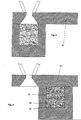
- FIG. 1 shows an injection molding tool, which is suitable for carrying out the method according to the invention and for producing a component according to the invention.
- the tool has essentially three components, namely a first tool half 10, which has a cavity 12 (FIG. Fig. 2 ), a second mold half 20, through which injection passages 22 extend, each terminating in an injection port connected to the cavity, and a slider 30 whose Y-position with respect to the two mold halves 10, 20 is variable.
- the position in the X-direction of the two mold halves 10, 20 is mutually variable in a conventional manner, so that the tool can be opened and closed.
- the cavity 12 is open at the top, that is, the cavity 12 has a granule filling opening 14, which preferably extends over the entire length and the entire width (XY plane) of the cavity.
- the slider 30, which is arranged above the two tool halves 10, 20, has a granule filling channel 32, which widens downwards in a funnel shape, so that it faces on the side of the slide 30, which points in the direction of the two tool halves 10, 20 , dekkungs GmbH with the granule filling opening 14 is.
- a hopper 40 may be provided above the slide 30, a hopper 40 may be provided.
- the slider 30 preferably overlaps both tool halves 10, 20 when the tool is in its closed state.
- the slider 30 further has a closed portion 34 which has no opening, so that the granule filling opening 14 can be sealed by the slider 30.
- the FIG. 2 shows a first process step.
- the granulate filling channel 32 is above the granulate filling opening 14 and granules, which consists of a multiplicity of particles 54, are introduced into the cavity 12 via the granulate filling channel 32.
- a typical diameter of a particle 54 is between 1 and 5 mm.
- the volume of a typical particle 54 is less than 1% of the volume of the cavity 12, so that the cavity 12 is relatively uniformly filled with granules.
- the filling with the granules 54 takes place without pressure, here exclusively by gravity.
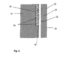
- the slider 30 When the filling is completed, the slider 30 is in the in FIG. 4 shown position and melted, hot plastic is injected through the injection channels 22 into the cavity 12 and completely fills the remaining cavity.
- the injection pressure is typically 400 to 1000 bar here.
- the particles 54 from the hot, flowable injected plastic 52 (this plastic is in the FIGS. 4 and 5 shown with checkered hatching) completely enclosed, so that in the resulting component 50 results in a structure that corresponds approximately to washed concrete.
- the particles 54 consist of they can be partially melted, so that a cohesive connection between the particles 54 and the injected plastic 52 can form.
- such a cohesive connection is not required, since the particles of the granules are already securely held in the component by their complete enveloping confinement by the injected plastic.
- Granules may consist of one or more plastics, mineral constituents, metal or a mixture of these materials. If the granules consist wholly or partly of plastic, then this plastic is usually at least partially different from the injected plastic 52nd
- the component 50 may typically have an area between 500 and 2500 cm 2 and a thickness between 10 and 20 mm, ie be plate-shaped.
- the pressure resistance corresponds approximately to the pressure resistance of such a component, which consist entirely of injected plastic 52.
- Preferred use of such a plate is a wall or a bottom plate.
- the described slider of the tool can also have more complex geometries in order to be able to remove, for example, undercuts or scenes. Furthermore, it is clear that it is also possible to design the tool so that the slider is moved in directions other than that shown.
- polypropylene is suitable as sheathing, injected plastics 52, but in principle any thermo-plastic material can be used.
Landscapes
- Engineering & Computer Science (AREA)
- Mechanical Engineering (AREA)
- Environmental & Geological Engineering (AREA)
- Manufacturing & Machinery (AREA)
- Injection Moulding Of Plastics Or The Like (AREA)
- Moulds For Moulding Plastics Or The Like (AREA)
Abstract
Description
- Die Erfindung betrifft ein Verfahren zur Herstellung eines Bauteils nach Anspruch 1, ein Bauteil nach Anspruch 10 sowie eine Verwendung eines solchen Bauteils nach Anspruch 13.
- Es ist in der Technik bekannt, plattenförmige Bauteile, welche insbesondere als Bodenplatten verwendet werden können, im Spritzgussverfahren aus Kunststoff herzustellen.
- Solche plattenförmigen Bauteile haben eine relativ große Fläche und eine im Verhältnis zur Fläche relativ geringe Dicke. Typische Abmessung eines solchen Bauteils sind 300 X 300 mm. Um die Menge des eingespritzten Kunstoffmaterials zu reduzieren und um wirtschaftliche Abkühlzeiten des Bauteils in der Spritzgussform zu erzielen, weisen solche Bauteile in der Regel Stege auf, das heißt, dass das Bauteil nicht über seine ganze Fläche eine einheitliche Dicke hat, sondern dass sich auf der Bodenseite des Bauteils Nuten befinden, welche durch die Stege voneinander getrennt sind. Ein solches Bauteil hat beispielsweise eine maximale Dicke von 10 mm und eine minimale Dicke von beispielsweise nur 3 mm. Dies hat den Nachteil, dass die maximale Druckbelastung, insbesondere die maximale punktuelle Druckbelastung, die ein solches Bauteil aufnehmen kann, begrenzt ist.
- Hiervon ausgehend stellt sich die vorliegende Erfindung deshalb zum einen, die Aufgabe, ein Verfahren zur Herstellung eines solchen Bauteils und ein Bauteil zur Verfügung zu stellen, mit dem erreicht werden kann, dass die Druckaufnahmefähigkeit eines solchen Bauteils erhöht werden kann.
- In der Technik besteht weiterhin das Problem, dass in der Kunststoffverarbeitung, aber auch bei anderen Prozessen, Abfallgranulate beziehungsweise Abfälle, welche zu einem Granulat vermahlen werden können, anfallen, für die es keine geeignete Wiederverwendung gibt, insbesondere dann, wenn die Granulate aus verschiedenen Materialien, beispielsweise aus verschiedenen Kunststoffen, oder aus Kunststoffen und Metallen bestehen.
- Die Erfindung stellt sich deswegen die weitere Aufgabe, ein Verfahren zur Verfügung zu stellen, mit dem solche Granulate sinnvoll weiterverarbeitet werden können.
- Die genannten Aufgaben werden durch ein Verfahren mit den Merkmalen des Anspruchs 1 und durch ein Bauteil mit den Merkmalen des Anspruchs 10 gelöst. Eine bevorzugte Verwendung eines solchen Bauteils ist in Anspruch 13 angegeben.
- Erfindungsgemäß wird das Bauteil nicht vollständig aus einem einzigen gussfähigen Kunststoff gefertigt, sondern das Bauteil enthält Granulat, welches von einem gussfähigen Kunststoff umspritzt ist. Dies hat mehrere Vorteile: Zum einen benötigt man auch dann, wenn das entsprechende Bauteil vollkommen massiv gefertigt wird, nur eine deutlich reduzierte Menge von gussfähigem Kunststoff, welcher ein wertvoller Rohstoff ist. Weiterhin ist das Granulat zu Beginn des Einspritzvorganges kalt, so dass die Gesamtwärmemenge des in einer Spritzgussform hergestellten Bauteils nach Abschluss des Einspritzvorgangs des gussfähigen Kunststoffmaterials gegenüber herkömmlichen Verfahren geringer ist, so dass deutlich geringere Abkühlzeiten notwendig werden und somit deutlich kühlere Zykluszeiten erreicht werden können. Schließlich wird eine sinnvolle Verwendung von Granulat zur Verfügung gestellt, welches bislang als Abfall entsorgt werden musste.
- Häufig wird es zu bevorzugen sein, dass das Granulat ein Abfallprodukt ist, es ist jedoch auch möglich, dass das Granulat kein Abfallprodukt ist, sondern beispielsweise aus mineralischen Bestandteilen wie kleinen Steinen oder ähnlichem besteht, oder solche Bestandteile zumindest enthält.
- Das Granulat kann aus vielen unterschiedlichen Fraktionen gemischt sein, beispielsweise aus verschiedenen Kunststoffen, Metallen und mineralischen Bestandteilen bestehen.
- Die Erfindung wird nun anhand eines Ausführungsbeispiels mit Bezug auf die Figuren näher erläutert. Hierbei zeigen:
- Figur 1
- eine Spritzgussform in einer perspektivischen Ansicht in einer sehr schematischen Darstellung,
- Figur 2
- einen Schnitt durch das Werkzeug aus
Figur 1 entlang der Schnittebene A-A während eines ersten Verfahrensschrittes ebenfalls in einer sehr schematischen Darstellung, - Figur 3
- das in
Figur 2 Gezeigte nach Abschluss des ersten Verfahrensschrittes, - Figur 4
- das in
Figur 3 Gezeigte nach Abschluss eines zweiten Verfahrensschrittes und - Figur 5
- einen Schnitt durch das Werkzeug aus
Figur 1 entlang der Schnittebene B-B nach Abschluss des Herstellungsprozesses, ebenfalls in einer sehr schematischen Darstellung und ohne Schieber. - Es muss zunächst vorausgeschickt werden, dass die Figuren sehr schematisch und nicht zwingend maßstäblich sind.
-
Figur 1 zeigt ein Spritzgusswerkzeug, welches zum Durchführen des erfindungsgemäßen Verfahrens und zur Herstellung eines erfindungsgemäßen Bauteils geeignet ist. Das Werkzeug weist im Wesentlichen drei Bestandteile auf, nämlich eine erste Werkzeughälfte 10, welche einen Hohlraum 12 (Fig. 2 ) umschließt, eine zweite Werkzeughälfte 20, durch welche sich Einspritzkanäle 22 erstrecken, die jeweils in einer mit dem Hohlraum verbundenen Einspritzöffnung enden, und einen Schieber 30, dessen Y-Position bezüglich der beiden Werkzeughälften 10, 20 veränderbar ist. Die Position in X-Richtung der beiden Werkzeughälften 10, 20 ist in üblicher Weise zueinander veränderbar, so dass das Werkzeug geöffnet und geschlossen werden kann. - Wie man der
Figur 1 und auch derFigur 2 entnimmt, ist der Hohlraum 12 nach oben offen, das heißt, der Hohlraum 12 weist eine Granulat-Einfüllöffnung 14 auf welche sich vorzugsweise über die gesamte Länge und die gesamte Breite (XY-Ebene) des Hohlraumes erstreckt. Der Schieber 30, welcher oberhalb der beiden Werkzeughälften 10, 20 angeordnet ist, weist einen Granulat-Einfüllkanal 32 auf, welcher sich nach unten trichterförmig aufweitet, so dass er auf der Seite des Schiebers 30, welcher in Richtung der beiden Werkzeughälften 10, 20 zeigt, dekkungsgleich mit der Granulat-Einfüllöffnung 14 ist. Oberhalb des Schiebers 30 kann ein Einfülltrichter 40 vorgesehen sein. Der Schieber 30 überlappt vorzugsweise beide Werkzeughälften 10, 20, wenn sich das Werkzeug in seinem geschlossenem Zustand befindet. Der Schieber 30 hat weiterhin einen geschlossenen Abschnitt 34, welcher keine Öffnung aufweist, so dass die Granulat-Einfüllöffnung 14 durch den Schieber 30 dicht verschlossen werden kann. - Die
Figur 2 zeigt einen ersten Verfahrensschritt. Hier befindet sich der Granulat-Einfüllkanal 32 über der Granulat-Einfüllöffnung 14 und Granulat, welches aus einer Vielzahl von Partikeln 54 besteht, wird über den Granulat-Einfüllkanal 32 in den Hohlraum 12 eingefüllt. Ein typischer Durchmesser eines Partikels 54 beträgt zwischen 1 und 5 mm. Das Volumen eines typischen Partikels 54 beträgt weniger als 1% des Volumens des Hohlraumes 12, so dass der Hohlraum 12 relativ gleichmäßig mit Granulat befüllt wird. Dadurch, dass der Granulat-Füllkanal 32 bündig mit der Granulat-Einfüllöffnung 14 abschließt, wird eine gleichmäßige Füllung des Hohlraums 12 über seine gesamte Höhe, Breite und Länge erreicht. Die Befüllung mit dem Granulat 54 erfolgt drucklos, hier ausschließlich durch Schwerkraft. Es wäre jedoch auch möglich, das Granulat in den Hohlraum 12 einzublasen. Nach Abschluss der Füllung des Hohlraumes durch Granulat (Figur 3 ) liegen die Partikel 54 des Granulates in lockerer Schüttung im Hohlraum 12 und füllen dabei typischerweise ca. 70 % des Hohlraumes 12 aus. - Ist die Füllung abgeschlossen, so wird der Schieber 30 in die in
Figur 4 gezeigte Stellung gebracht und geschmolzener, heißer Kunststoff wird durch die Einspritzkanäle 22 in den Hohlraum 12 eingespritzt und füllt den verbleibenden Hohlraum vollständig aus. Der Einspritzdruck beträgt hier typischerweise 400 bis 1000 bar. Hierdurch werden die Partikel 54 vom heißen, fließfähigen eingespritzten Kunststoff 52 (dieser Kunststoff ist in denFiguren 4 und5 mit karierter Schraffur dargestellt) vollständig umschlossen, so dass sich im entstehenden Bauteil 50 eine Struktur ergibt, wie sie in etwa Waschbeton entspricht. Je nach dem, aus welchem Material die Partikel 54 bestehen, können diese teilweise angeschmolzen werden, so dass sich auch eine stoffschlüssige Verbindung zwischen den Partikeln 54 und dem eingespritzten Kunststoff 52 bilden kann. Erforderlich ist eine solche stoffschlüssige Verbindung jedoch nicht, da die Partikel des Granulat schon allein durch ihren vollständigen ummantelnden Einschluss durch den eingespritzten Kunststoff sicher im Bauteil gehalten sind. - Ein Granulat kann aus einem oder mehreren Kunststoffen, aus mineralischen Bestandteilen, aus Metall oder einer Mischung dieser Materialien bestehen. Besteht das Granulat ganz oder teilweise aus Kunststoff, so ist dieser Kunststoff in der Regel zumindest teilweise verschieden vom eingespritzten Kunststoff 52.
- Nach Abschluss des Einspritzens (zweiter Verfahrensschritt) und Abkühlen des Bauteils 50 werden erste und zweite Werkzeughälfte 10, 20 in gewohnter Weise auseinander gefahren und das Bauteil 50 kann entnommen werden. Das Bauteil 50 kann typischerweise eine Fläche zwischen 500 und 2500 cm2 und eine Dicke zwischen 10 und 20 mm haben, also plattenförmig sein.
- Die Druckbeständigkeit entspricht in etwa der Druckbeständigkeit eines solchen Bauteils, das vollständig aus eingespritzem Kunststoff 52 bestände.
- Bevorzugte Verwendung einer solchen Platte ist eine Wand oder auch eine Bodenplatte.
- Die Erfindung wurde anhand eines plattenförmigen Bauteils erläutert, es ist jedoch zu betonen, dass es auch möglich ist, andere Bauteile herzustellen, beispielsweise blockartige, stangenförmige oder im wesentlichen runde Bauteile.
- Es ist noch zu betonen, dass der beschriebene Schieber des Werkzeugs auch komplexere Geometrien aufweisen kann, um beispielsweise Hinterschneidungen oder Kulissen entformen zu können. Weiterhin ist klar, dass es auch möglich ist, das Werkzeug so auszugestalten, dass der Schieber in anderen Richtungen als der gezeigten bewegt wird.
- Als ummantelnde, eingespritze Kunsstoffe 52 eignen sich insbesondere Polypropylen, wobei jedoch grundsätzlich jeder thermopastische Kunststoff verwendet werden kann.
-
- 10
- erste Werkzeughälfte
- 12
- Hohlraum
- 14
- Granulat-Einfüllöffnung
- 20
- zweite Werkeughälfte
- 22
- Einspritzkanal
- 30
- Schieber
- 32
- Granulat-Einfüllkanal
- 34
- geschlossener Abschnitt
- 40
- Einfüll-Trichter
- 50
- Bauteil
- 52
- umspritzter Kunststoff
- 54
- Partikel
Claims (13)
- Verfahren zur Herstellung eines Bauteils (50) mit folgenden Schritten:- Einfüllen von Granulat in den Hohlraum (12) einer Spritzgussform durch wenigstens eine Granulat-Einfüllöffnung (14),- Schließen der Granulat-Einfüllöffnung (14).- Einspritzen von verflüssigtem Kunststoff in den Hohlraum (12) durch wenigstens eine Einspritzöffnung, so dass nach Abschluss des Einspritzvorgangs der Hohlraum (12) vollständig von Granulat und Kunststoff ausgefüllt ist,- Öffnen der Spritzgussform und Entnehmen des Kunststoffelements.
- Verfahren nach Anspruch 1, dadurch gekennzeichnet, dass das Einfüllen des Granulats drucklos, vorzugsweise von oben erfolgt.
- Verfahren nach einem der vorangehenden Ansprüche, dadurch gekennzeichnet, dass das Einspritzen des Kunststoffs mit einem Druck von wenigstens 400 bar erfolgt.
- Verfahren nach einem der vorangehenden Ansprüche, dadurch gekennzeichnet, dass das maximale Volumen eines Partikels (54) des Granulats 1% des Volumens des Hohlraums (12) entspricht.
- Verfahren nach einem der vorangehenden Ansprüche, dadurch gekennzeichnet, dass das Granulat Kunststoffpartikel enthält.
- Verfahren nach Anspruch 5, dadurch gekennzeichnet, dass die Kunststoffpartikel aus einem Kunststoff bestehen, welcher vom eingespritzten Kunststoff verschieden ist.
- Verfahren nach Anspruch 5 oder Anspruch 6, dadurch gekennzeichnet, dass das Granulat Kunststoffpartikel aus wenigstens zwei unterschiedlichen Kunststoffen enthält.
- Verfahren nach einem der Ansprüche 5 bis 7, dadurch gekennzeichnet, dass das Granulat Metall enthält.
- Verfahren nach einem der Ansprüche 5 bis 8, dadurch gekennzeichnet, dass das Granulat mineralische Partikel enthält.
- Bauteil (50) bestehend aus Granulat und Kunststoff, von welchem das Granulat umspritzt oder umgossen ist.
- Bauteil nach Anspruch 10, welches nach einem der Ansprüche 1 bis 9 hergestellt ist.
- Bauteil nach Anspruch 10 oder Anspruch 11, dadurch gekennzeichnet, dass es ein plattenförmiges Element mit einer Dicke zwischen 5 und 20 mm und einer Fläche von wenigstens 500 cm2 ist.
- Verwendung eines Bauteils nach Anspruch 12 als Wand- oder Bodenplatte.
Applications Claiming Priority (1)
| Application Number | Priority Date | Filing Date | Title |
|---|---|---|---|
| DE201010056360 DE102010056360A1 (de) | 2010-12-29 | 2010-12-29 | Verfahren zur Herstellung eines Bauteils, Bauteil und Verwendung eines Bauteils |
Publications (2)
| Publication Number | Publication Date |
|---|---|
| EP2471645A1 true EP2471645A1 (de) | 2012-07-04 |
| EP2471645B1 EP2471645B1 (de) | 2014-07-23 |
Family
ID=45524223
Family Applications (1)
| Application Number | Title | Priority Date | Filing Date |
|---|---|---|---|
| EP20110010263 Active EP2471645B1 (de) | 2010-12-29 | 2011-12-28 | Verfahren zur Herstellung eines Bauteils |
Country Status (2)
| Country | Link |
|---|---|
| EP (1) | EP2471645B1 (de) |
| DE (1) | DE102010056360A1 (de) |
Citations (6)
| Publication number | Priority date | Publication date | Assignee | Title |
|---|---|---|---|---|
| DE3128623A1 (de) * | 1980-07-21 | 1982-04-15 | Pont-à-Mousson S.A., 54017 Nancy | Spritzgiessverfahren zur herstellung von ueberzogenen kunststofformteilen und vorrichtung zur durchfuehrung dieses verfahrens |
| DD265409A1 (de) * | 1987-10-08 | 1989-03-01 | Leuna Werke Veb | Verstaerkter plast |
| DE3917751A1 (de) * | 1989-05-31 | 1990-12-06 | Wilden Kg | Verfahren und vorrichtung zum herstellen von eine vielzahl fuellkoerper enthaltenden formteilen aus kunststoff |
| JPH0399814A (ja) * | 1989-09-13 | 1991-04-25 | Mitsuboshi Belting Ltd | 固体充てん材を含む複合材料の成形方法 |
| EP0473990A2 (de) * | 1990-08-24 | 1992-03-11 | BASF Aktiengesellschaft | Wiederverwertung von Kunststoff-Altteilen und -Abfällen |
| EP1486311A1 (de) * | 2003-06-14 | 2004-12-15 | University Of Warwick | Beschichtung von spritzgegossenen Formteilen |
Family Cites Families (3)
| Publication number | Priority date | Publication date | Assignee | Title |
|---|---|---|---|---|
| DE4244535C2 (de) * | 1992-12-30 | 1996-08-08 | Braun Pebra Gmbh | Strukturmaterial aus miteinander verbundenen Partikeln, das von Kanälen durchsetzt ist |
| DE29518977U1 (de) * | 1995-11-30 | 1996-02-01 | Eickenroth Hans Dieter | Kunststoff-Partikel enthaltender Drainage-Belag |
| DE102006044276A1 (de) * | 2005-10-25 | 2007-04-26 | Albea Kunststofftechnik Gmbh & Co Kg | Spritzguss-Verbundteil |
-
2010
- 2010-12-29 DE DE201010056360 patent/DE102010056360A1/de not_active Withdrawn
-
2011
- 2011-12-28 EP EP20110010263 patent/EP2471645B1/de active Active
Patent Citations (7)
| Publication number | Priority date | Publication date | Assignee | Title |
|---|---|---|---|---|
| DE3128623A1 (de) * | 1980-07-21 | 1982-04-15 | Pont-à-Mousson S.A., 54017 Nancy | Spritzgiessverfahren zur herstellung von ueberzogenen kunststofformteilen und vorrichtung zur durchfuehrung dieses verfahrens |
| DD265409A1 (de) * | 1987-10-08 | 1989-03-01 | Leuna Werke Veb | Verstaerkter plast |
| DE3917751A1 (de) * | 1989-05-31 | 1990-12-06 | Wilden Kg | Verfahren und vorrichtung zum herstellen von eine vielzahl fuellkoerper enthaltenden formteilen aus kunststoff |
| JPH0399814A (ja) * | 1989-09-13 | 1991-04-25 | Mitsuboshi Belting Ltd | 固体充てん材を含む複合材料の成形方法 |
| US5736081A (en) * | 1989-09-13 | 1998-04-07 | Mitsuboshi Belting Ltd. | Method and apparatus for forming composite material including solid filler particles |
| EP0473990A2 (de) * | 1990-08-24 | 1992-03-11 | BASF Aktiengesellschaft | Wiederverwertung von Kunststoff-Altteilen und -Abfällen |
| EP1486311A1 (de) * | 2003-06-14 | 2004-12-15 | University Of Warwick | Beschichtung von spritzgegossenen Formteilen |
Also Published As
| Publication number | Publication date |
|---|---|
| DE102010056360A1 (de) | 2012-07-05 |
| EP2471645B1 (de) | 2014-07-23 |
Similar Documents
| Publication | Publication Date | Title |
|---|---|---|
| DE69219157T3 (de) | Spritzgiessen von kunststoffgegenständen die hohlförmige rippen aufweisen | |
| EP3790732B1 (de) | Verfahren zur herstellung einer sohle eines schuhs, insbesondere eines sportschuhs | |
| DE19620646C2 (de) | Verfahren zur Herstellung von hochwertigen Kunststoffteilen | |
| DE60011883T2 (de) | Formvorrichtung zum polymerisieren von profilierten teilen aus verbundwerkstoff | |
| EP1980383B1 (de) | Pressformverfahren und Anlage zur Herstellung von Bauteilen aus langfaserverstärktem Thermoplast | |
| DE3020906A1 (de) | Vorrichtung zum umspritzen oder umgiessen der raeder flaechiger bauteile, insbesondere beschichteter spanplatten | |
| DE102008060080B4 (de) | Zweifarben-Formungsverfahren | |
| EP2471645B1 (de) | Verfahren zur Herstellung eines Bauteils | |
| EP3098049A1 (de) | Verfahren und vorrichtung zur beeinflussung eines zusammentreffens von mindestens zwei kunststoffschmelzen während einer herstellung eines formkörpers in einem spritzgiessverfahren | |
| EP2664437B1 (de) | Werkzeug und Verfahren zur Herstellung von bindenahtoptimierten Formteilen | |
| DE102006026298B4 (de) | Vorrichtung und Verfahren zur Herstellung von Formteilen im Spritzgussverfahren | |
| DE102017215528A1 (de) | Napf oder Napfstreifen und Verfahren zu seiner Herstellung | |
| DE19757387A1 (de) | Spritzgießvorrichtung | |
| DE10255993B4 (de) | Spritzgießwerkzeug und zugehöriges Verfahren | |
| DE112018004696T5 (de) | Kunststoffspritzguss und Prozess | |
| DE102007015216B4 (de) | Vorrichtung und Verfahren zur Herstellung eines Hohlkörpers aus mindestens zwei Schichten Kunststoff | |
| DE102015200763A1 (de) | Verfahren und Werkzeug zur Herstellung eines Faserverbund-Bauteils | |
| DE102006004476A1 (de) | Verfahren zur Herstellung eines Formteils und ein nach diesem Verfahren hergestelltes Formteil | |
| DE19918776A1 (de) | Formwerkzeug zur Herstellung von mehreren montagegespritzten Bauteilen | |
| DE10252737A1 (de) | Formteil, insbesondere Kfz-Innenverkleidungsteil, und Verfahren zu seiner Herstellung | |
| DE3815063A1 (de) | Verfahren und vorrichtung zur herstellung eines bauteils aus kunstoff | |
| DE10339098B4 (de) | Werkzeug zum Spritzgießen eines Kastens | |
| DE2230250A1 (de) | Verfahren und vorrichtung zum herstellen von profilleisten beliebiger laenge aus kunststoff, insbesondere einem struktur-schaumstoff | |
| DE102022110064A1 (de) | Verfahren zum Herstellen eines Zahnrads durch Spritzprägen | |
| WO2013093064A1 (de) | Verfahren zur herstellung eines dickwandigen kunststoffteils |
Legal Events
| Date | Code | Title | Description |
|---|---|---|---|
| AK | Designated contracting states |
Kind code of ref document: A1 Designated state(s): AL AT BE BG CH CY CZ DE DK EE ES FI FR GB GR HR HU IE IS IT LI LT LU LV MC MK MT NL NO PL PT RO RS SE SI SK SM TR |
|
| AX | Request for extension of the european patent |
Extension state: BA ME |
|
| PUAI | Public reference made under article 153(3) epc to a published international application that has entered the european phase |
Free format text: ORIGINAL CODE: 0009012 |
|
| 17P | Request for examination filed |
Effective date: 20130422 |
|
| 17Q | First examination report despatched |
Effective date: 20130620 |
|
| GRAP | Despatch of communication of intention to grant a patent |
Free format text: ORIGINAL CODE: EPIDOSNIGR1 |
|
| INTG | Intention to grant announced |
Effective date: 20140320 |
|
| GRAS | Grant fee paid |
Free format text: ORIGINAL CODE: EPIDOSNIGR3 |
|
| GRAA | (expected) grant |
Free format text: ORIGINAL CODE: 0009210 |
|
| AK | Designated contracting states |
Kind code of ref document: B1 Designated state(s): AL AT BE BG CH CY CZ DE DK EE ES FI FR GB GR HR HU IE IS IT LI LT LU LV MC MK MT NL NO PL PT RO RS SE SI SK SM TR |
|
| REG | Reference to a national code |
Ref country code: GB Ref legal event code: FG4D Free format text: NOT ENGLISH |
|
| REG | Reference to a national code |
Ref country code: CH Ref legal event code: EP |
|
| REG | Reference to a national code |
Ref country code: IE Ref legal event code: FG4D Free format text: LANGUAGE OF EP DOCUMENT: GERMAN |
|
| REG | Reference to a national code |
Ref country code: AT Ref legal event code: REF Ref document number: 678596 Country of ref document: AT Kind code of ref document: T Effective date: 20140815 |
|
| REG | Reference to a national code |
Ref country code: DE Ref legal event code: R096 Ref document number: 502011003813 Country of ref document: DE Effective date: 20140828 |
|
| REG | Reference to a national code |
Ref country code: NL Ref legal event code: VDEP Effective date: 20140723 |
|
| REG | Reference to a national code |
Ref country code: LT Ref legal event code: MG4D |
|
| PG25 | Lapsed in a contracting state [announced via postgrant information from national office to epo] |
Ref country code: ES Free format text: LAPSE BECAUSE OF FAILURE TO SUBMIT A TRANSLATION OF THE DESCRIPTION OR TO PAY THE FEE WITHIN THE PRESCRIBED TIME-LIMIT Effective date: 20140723 Ref country code: GR Free format text: LAPSE BECAUSE OF FAILURE TO SUBMIT A TRANSLATION OF THE DESCRIPTION OR TO PAY THE FEE WITHIN THE PRESCRIBED TIME-LIMIT Effective date: 20141024 Ref country code: PT Free format text: LAPSE BECAUSE OF FAILURE TO SUBMIT A TRANSLATION OF THE DESCRIPTION OR TO PAY THE FEE WITHIN THE PRESCRIBED TIME-LIMIT Effective date: 20141124 Ref country code: NO Free format text: LAPSE BECAUSE OF FAILURE TO SUBMIT A TRANSLATION OF THE DESCRIPTION OR TO PAY THE FEE WITHIN THE PRESCRIBED TIME-LIMIT Effective date: 20141023 Ref country code: BG Free format text: LAPSE BECAUSE OF FAILURE TO SUBMIT A TRANSLATION OF THE DESCRIPTION OR TO PAY THE FEE WITHIN THE PRESCRIBED TIME-LIMIT Effective date: 20141023 Ref country code: LT Free format text: LAPSE BECAUSE OF FAILURE TO SUBMIT A TRANSLATION OF THE DESCRIPTION OR TO PAY THE FEE WITHIN THE PRESCRIBED TIME-LIMIT Effective date: 20140723 Ref country code: FI Free format text: LAPSE BECAUSE OF FAILURE TO SUBMIT A TRANSLATION OF THE DESCRIPTION OR TO PAY THE FEE WITHIN THE PRESCRIBED TIME-LIMIT Effective date: 20140723 Ref country code: SE Free format text: LAPSE BECAUSE OF FAILURE TO SUBMIT A TRANSLATION OF THE DESCRIPTION OR TO PAY THE FEE WITHIN THE PRESCRIBED TIME-LIMIT Effective date: 20140723 |
|
| PG25 | Lapsed in a contracting state [announced via postgrant information from national office to epo] |
Ref country code: RS Free format text: LAPSE BECAUSE OF FAILURE TO SUBMIT A TRANSLATION OF THE DESCRIPTION OR TO PAY THE FEE WITHIN THE PRESCRIBED TIME-LIMIT Effective date: 20140723 Ref country code: CY Free format text: LAPSE BECAUSE OF FAILURE TO SUBMIT A TRANSLATION OF THE DESCRIPTION OR TO PAY THE FEE WITHIN THE PRESCRIBED TIME-LIMIT Effective date: 20140723 Ref country code: HR Free format text: LAPSE BECAUSE OF FAILURE TO SUBMIT A TRANSLATION OF THE DESCRIPTION OR TO PAY THE FEE WITHIN THE PRESCRIBED TIME-LIMIT Effective date: 20140723 Ref country code: IS Free format text: LAPSE BECAUSE OF FAILURE TO SUBMIT A TRANSLATION OF THE DESCRIPTION OR TO PAY THE FEE WITHIN THE PRESCRIBED TIME-LIMIT Effective date: 20141123 Ref country code: NL Free format text: LAPSE BECAUSE OF FAILURE TO SUBMIT A TRANSLATION OF THE DESCRIPTION OR TO PAY THE FEE WITHIN THE PRESCRIBED TIME-LIMIT Effective date: 20140723 Ref country code: LV Free format text: LAPSE BECAUSE OF FAILURE TO SUBMIT A TRANSLATION OF THE DESCRIPTION OR TO PAY THE FEE WITHIN THE PRESCRIBED TIME-LIMIT Effective date: 20140723 Ref country code: PL Free format text: LAPSE BECAUSE OF FAILURE TO SUBMIT A TRANSLATION OF THE DESCRIPTION OR TO PAY THE FEE WITHIN THE PRESCRIBED TIME-LIMIT Effective date: 20140723 |
|
| REG | Reference to a national code |
Ref country code: DE Ref legal event code: R097 Ref document number: 502011003813 Country of ref document: DE |
|
| PG25 | Lapsed in a contracting state [announced via postgrant information from national office to epo] |
Ref country code: IT Free format text: LAPSE BECAUSE OF FAILURE TO SUBMIT A TRANSLATION OF THE DESCRIPTION OR TO PAY THE FEE WITHIN THE PRESCRIBED TIME-LIMIT Effective date: 20140723 Ref country code: DK Free format text: LAPSE BECAUSE OF FAILURE TO SUBMIT A TRANSLATION OF THE DESCRIPTION OR TO PAY THE FEE WITHIN THE PRESCRIBED TIME-LIMIT Effective date: 20140723 Ref country code: EE Free format text: LAPSE BECAUSE OF FAILURE TO SUBMIT A TRANSLATION OF THE DESCRIPTION OR TO PAY THE FEE WITHIN THE PRESCRIBED TIME-LIMIT Effective date: 20140723 Ref country code: RO Free format text: LAPSE BECAUSE OF FAILURE TO SUBMIT A TRANSLATION OF THE DESCRIPTION OR TO PAY THE FEE WITHIN THE PRESCRIBED TIME-LIMIT Effective date: 20140723 Ref country code: SK Free format text: LAPSE BECAUSE OF FAILURE TO SUBMIT A TRANSLATION OF THE DESCRIPTION OR TO PAY THE FEE WITHIN THE PRESCRIBED TIME-LIMIT Effective date: 20140723 Ref country code: CZ Free format text: LAPSE BECAUSE OF FAILURE TO SUBMIT A TRANSLATION OF THE DESCRIPTION OR TO PAY THE FEE WITHIN THE PRESCRIBED TIME-LIMIT Effective date: 20140723 |
|
| PLBE | No opposition filed within time limit |
Free format text: ORIGINAL CODE: 0009261 |
|
| STAA | Information on the status of an ep patent application or granted ep patent |
Free format text: STATUS: NO OPPOSITION FILED WITHIN TIME LIMIT |
|
| PG25 | Lapsed in a contracting state [announced via postgrant information from national office to epo] |
Ref country code: BE Free format text: LAPSE BECAUSE OF NON-PAYMENT OF DUE FEES Effective date: 20141231 |
|
| 26N | No opposition filed |
Effective date: 20150424 |
|
| PG25 | Lapsed in a contracting state [announced via postgrant information from national office to epo] |
Ref country code: LU Free format text: LAPSE BECAUSE OF FAILURE TO SUBMIT A TRANSLATION OF THE DESCRIPTION OR TO PAY THE FEE WITHIN THE PRESCRIBED TIME-LIMIT Effective date: 20141228 |
|
| REG | Reference to a national code |
Ref country code: CH Ref legal event code: PL |
|
| REG | Reference to a national code |
Ref country code: IE Ref legal event code: MM4A |
|
| REG | Reference to a national code |
Ref country code: FR Ref legal event code: ST Effective date: 20150831 |
|
| PG25 | Lapsed in a contracting state [announced via postgrant information from national office to epo] |
Ref country code: CH Free format text: LAPSE BECAUSE OF NON-PAYMENT OF DUE FEES Effective date: 20141231 Ref country code: IE Free format text: LAPSE BECAUSE OF NON-PAYMENT OF DUE FEES Effective date: 20141228 Ref country code: LI Free format text: LAPSE BECAUSE OF NON-PAYMENT OF DUE FEES Effective date: 20141231 |
|
| PG25 | Lapsed in a contracting state [announced via postgrant information from national office to epo] |
Ref country code: SI Free format text: LAPSE BECAUSE OF FAILURE TO SUBMIT A TRANSLATION OF THE DESCRIPTION OR TO PAY THE FEE WITHIN THE PRESCRIBED TIME-LIMIT Effective date: 20140723 Ref country code: FR Free format text: LAPSE BECAUSE OF NON-PAYMENT OF DUE FEES Effective date: 20141231 |
|
| PG25 | Lapsed in a contracting state [announced via postgrant information from national office to epo] |
Ref country code: SM Free format text: LAPSE BECAUSE OF FAILURE TO SUBMIT A TRANSLATION OF THE DESCRIPTION OR TO PAY THE FEE WITHIN THE PRESCRIBED TIME-LIMIT Effective date: 20140723 |
|
| PG25 | Lapsed in a contracting state [announced via postgrant information from national office to epo] |
Ref country code: MC Free format text: LAPSE BECAUSE OF FAILURE TO SUBMIT A TRANSLATION OF THE DESCRIPTION OR TO PAY THE FEE WITHIN THE PRESCRIBED TIME-LIMIT Effective date: 20140723 |
|
| PG25 | Lapsed in a contracting state [announced via postgrant information from national office to epo] |
Ref country code: HU Free format text: LAPSE BECAUSE OF FAILURE TO SUBMIT A TRANSLATION OF THE DESCRIPTION OR TO PAY THE FEE WITHIN THE PRESCRIBED TIME-LIMIT; INVALID AB INITIO Effective date: 20111228 Ref country code: MT Free format text: LAPSE BECAUSE OF FAILURE TO SUBMIT A TRANSLATION OF THE DESCRIPTION OR TO PAY THE FEE WITHIN THE PRESCRIBED TIME-LIMIT Effective date: 20140723 Ref country code: TR Free format text: LAPSE BECAUSE OF FAILURE TO SUBMIT A TRANSLATION OF THE DESCRIPTION OR TO PAY THE FEE WITHIN THE PRESCRIBED TIME-LIMIT Effective date: 20140723 |
|
| GBPC | Gb: european patent ceased through non-payment of renewal fee |
Effective date: 20151228 |
|
| PG25 | Lapsed in a contracting state [announced via postgrant information from national office to epo] |
Ref country code: GB Free format text: LAPSE BECAUSE OF NON-PAYMENT OF DUE FEES Effective date: 20151228 |
|
| REG | Reference to a national code |
Ref country code: AT Ref legal event code: MM01 Ref document number: 678596 Country of ref document: AT Kind code of ref document: T Effective date: 20161228 |
|
| PG25 | Lapsed in a contracting state [announced via postgrant information from national office to epo] |
Ref country code: AT Free format text: LAPSE BECAUSE OF NON-PAYMENT OF DUE FEES Effective date: 20161228 |
|
| REG | Reference to a national code |
Ref country code: DE Ref legal event code: R082 Ref document number: 502011003813 Country of ref document: DE Representative=s name: SCHOEN, THILO, DIPL.-PHYS., DE |
|
| PG25 | Lapsed in a contracting state [announced via postgrant information from national office to epo] |
Ref country code: MK Free format text: LAPSE BECAUSE OF FAILURE TO SUBMIT A TRANSLATION OF THE DESCRIPTION OR TO PAY THE FEE WITHIN THE PRESCRIBED TIME-LIMIT Effective date: 20140723 |
|
| PG25 | Lapsed in a contracting state [announced via postgrant information from national office to epo] |
Ref country code: AL Free format text: LAPSE BECAUSE OF FAILURE TO SUBMIT A TRANSLATION OF THE DESCRIPTION OR TO PAY THE FEE WITHIN THE PRESCRIBED TIME-LIMIT Effective date: 20140723 |
|
| PGFP | Annual fee paid to national office [announced via postgrant information from national office to epo] |
Ref country code: DE Payment date: 20240219 Year of fee payment: 13 |