EP2470814B1 - Vorrichtung zur rohrbruchsicherung - Google Patents
Vorrichtung zur rohrbruchsicherung Download PDFInfo
- Publication number
- EP2470814B1 EP2470814B1 EP20100747193 EP10747193A EP2470814B1 EP 2470814 B1 EP2470814 B1 EP 2470814B1 EP 20100747193 EP20100747193 EP 20100747193 EP 10747193 A EP10747193 A EP 10747193A EP 2470814 B1 EP2470814 B1 EP 2470814B1
- Authority
- EP
- European Patent Office
- Prior art keywords
- closing
- outflow
- inflow
- test
- closing element
- Prior art date
- Legal status (The legal status is an assumption and is not a legal conclusion. Google has not performed a legal analysis and makes no representation as to the accuracy of the status listed.)
- Active
Links
Images


Classifications
-
- F—MECHANICAL ENGINEERING; LIGHTING; HEATING; WEAPONS; BLASTING
- F16—ENGINEERING ELEMENTS AND UNITS; GENERAL MEASURES FOR PRODUCING AND MAINTAINING EFFECTIVE FUNCTIONING OF MACHINES OR INSTALLATIONS; THERMAL INSULATION IN GENERAL
- F16K—VALVES; TAPS; COCKS; ACTUATING-FLOATS; DEVICES FOR VENTING OR AERATING
- F16K17/00—Safety valves; Equalising valves, e.g. pressure relief valves
- F16K17/20—Excess-flow valves
- F16K17/22—Excess-flow valves actuated by the difference of pressure between two places in the flow line
- F16K17/24—Excess-flow valves actuated by the difference of pressure between two places in the flow line acting directly on the cutting-off member
- F16K17/28—Excess-flow valves actuated by the difference of pressure between two places in the flow line acting directly on the cutting-off member operating in one direction only
- F16K17/30—Excess-flow valves actuated by the difference of pressure between two places in the flow line acting directly on the cutting-off member operating in one direction only spring-loaded
-
- G—PHYSICS
- G05—CONTROLLING; REGULATING
- G05D—SYSTEMS FOR CONTROLLING OR REGULATING NON-ELECTRIC VARIABLES
- G05D7/00—Control of flow
- G05D7/01—Control of flow without auxiliary power
- G05D7/0126—Control of flow without auxiliary power the sensing element being a piston or plunger associated with one or more springs
- G05D7/0133—Control of flow without auxiliary power the sensing element being a piston or plunger associated with one or more springs within the flow-path
- G05D7/014—Control of flow without auxiliary power the sensing element being a piston or plunger associated with one or more springs within the flow-path using sliding elements
-
- Y—GENERAL TAGGING OF NEW TECHNOLOGICAL DEVELOPMENTS; GENERAL TAGGING OF CROSS-SECTIONAL TECHNOLOGIES SPANNING OVER SEVERAL SECTIONS OF THE IPC; TECHNICAL SUBJECTS COVERED BY FORMER USPC CROSS-REFERENCE ART COLLECTIONS [XRACs] AND DIGESTS
- Y10—TECHNICAL SUBJECTS COVERED BY FORMER USPC
- Y10T—TECHNICAL SUBJECTS COVERED BY FORMER US CLASSIFICATION
- Y10T137/00—Fluid handling
- Y10T137/598—With repair, tapping, assembly, or disassembly means
- Y10T137/6086—Assembling or disassembling check valve
-
- Y—GENERAL TAGGING OF NEW TECHNOLOGICAL DEVELOPMENTS; GENERAL TAGGING OF CROSS-SECTIONAL TECHNOLOGIES SPANNING OVER SEVERAL SECTIONS OF THE IPC; TECHNICAL SUBJECTS COVERED BY FORMER USPC CROSS-REFERENCE ART COLLECTIONS [XRACs] AND DIGESTS
- Y10—TECHNICAL SUBJECTS COVERED BY FORMER USPC
- Y10T—TECHNICAL SUBJECTS COVERED BY FORMER US CLASSIFICATION
- Y10T137/00—Fluid handling
- Y10T137/6851—With casing, support, protector or static constructional installations
- Y10T137/6855—Vehicle
- Y10T137/6906—Aerial or water-supported [e.g., airplane or ship, etc.]
-
- Y—GENERAL TAGGING OF NEW TECHNOLOGICAL DEVELOPMENTS; GENERAL TAGGING OF CROSS-SECTIONAL TECHNOLOGIES SPANNING OVER SEVERAL SECTIONS OF THE IPC; TECHNICAL SUBJECTS COVERED BY FORMER USPC CROSS-REFERENCE ART COLLECTIONS [XRACs] AND DIGESTS
- Y10—TECHNICAL SUBJECTS COVERED BY FORMER USPC
- Y10T—TECHNICAL SUBJECTS COVERED BY FORMER US CLASSIFICATION
- Y10T137/00—Fluid handling
- Y10T137/7722—Line condition change responsive valves
- Y10T137/7723—Safety cut-off requiring reset
- Y10T137/7726—Responsive to change in rate of flow
- Y10T137/7727—Excessive flow cut-off
-
- Y—GENERAL TAGGING OF NEW TECHNOLOGICAL DEVELOPMENTS; GENERAL TAGGING OF CROSS-SECTIONAL TECHNOLOGIES SPANNING OVER SEVERAL SECTIONS OF THE IPC; TECHNICAL SUBJECTS COVERED BY FORMER USPC CROSS-REFERENCE ART COLLECTIONS [XRACs] AND DIGESTS
- Y10—TECHNICAL SUBJECTS COVERED BY FORMER USPC
- Y10T—TECHNICAL SUBJECTS COVERED BY FORMER US CLASSIFICATION
- Y10T137/00—Fluid handling
- Y10T137/7722—Line condition change responsive valves
- Y10T137/7781—With separate connected fluid reactor surface
- Y10T137/7784—Responsive to change in rate of fluid flow
- Y10T137/7785—Valve closes in response to excessive flow
-
- Y—GENERAL TAGGING OF NEW TECHNOLOGICAL DEVELOPMENTS; GENERAL TAGGING OF CROSS-SECTIONAL TECHNOLOGIES SPANNING OVER SEVERAL SECTIONS OF THE IPC; TECHNICAL SUBJECTS COVERED BY FORMER USPC CROSS-REFERENCE ART COLLECTIONS [XRACs] AND DIGESTS
- Y10—TECHNICAL SUBJECTS COVERED BY FORMER USPC
- Y10T—TECHNICAL SUBJECTS COVERED BY FORMER US CLASSIFICATION
- Y10T137/00—Fluid handling
- Y10T137/7722—Line condition change responsive valves
- Y10T137/7837—Direct response valves [i.e., check valve type]
- Y10T137/7869—Biased open
-
- Y—GENERAL TAGGING OF NEW TECHNOLOGICAL DEVELOPMENTS; GENERAL TAGGING OF CROSS-SECTIONAL TECHNOLOGIES SPANNING OVER SEVERAL SECTIONS OF THE IPC; TECHNICAL SUBJECTS COVERED BY FORMER USPC CROSS-REFERENCE ART COLLECTIONS [XRACs] AND DIGESTS
- Y10—TECHNICAL SUBJECTS COVERED BY FORMER USPC
- Y10T—TECHNICAL SUBJECTS COVERED BY FORMER US CLASSIFICATION
- Y10T137/00—Fluid handling
- Y10T137/7722—Line condition change responsive valves
- Y10T137/7837—Direct response valves [i.e., check valve type]
- Y10T137/7904—Reciprocating valves
- Y10T137/7922—Spring biased
-
- Y—GENERAL TAGGING OF NEW TECHNOLOGICAL DEVELOPMENTS; GENERAL TAGGING OF CROSS-SECTIONAL TECHNOLOGIES SPANNING OVER SEVERAL SECTIONS OF THE IPC; TECHNICAL SUBJECTS COVERED BY FORMER USPC CROSS-REFERENCE ART COLLECTIONS [XRACs] AND DIGESTS
- Y10—TECHNICAL SUBJECTS COVERED BY FORMER USPC
- Y10T—TECHNICAL SUBJECTS COVERED BY FORMER US CLASSIFICATION
- Y10T137/00—Fluid handling
- Y10T137/8593—Systems
- Y10T137/87265—Dividing into parallel flow paths with recombining
- Y10T137/87539—Having guide or restrictor
- Y10T137/87547—Manually variable
-
- Y—GENERAL TAGGING OF NEW TECHNOLOGICAL DEVELOPMENTS; GENERAL TAGGING OF CROSS-SECTIONAL TECHNOLOGIES SPANNING OVER SEVERAL SECTIONS OF THE IPC; TECHNICAL SUBJECTS COVERED BY FORMER USPC CROSS-REFERENCE ART COLLECTIONS [XRACs] AND DIGESTS
- Y10—TECHNICAL SUBJECTS COVERED BY FORMER USPC
- Y10T—TECHNICAL SUBJECTS COVERED BY FORMER US CLASSIFICATION
- Y10T137/00—Fluid handling
- Y10T137/8593—Systems
- Y10T137/87265—Dividing into parallel flow paths with recombining
- Y10T137/87555—Having direct response valve [e.g., check valve, etc.]
Definitions
- the invention relates to a device for pipe rupture protection, a method for testing a device for pipe rupture protection, a use of such a device for pipe rupture protection and an aircraft with at least one device for pipe rupture protection, which is adapted to carry out the inventive method.
- pipe rupture failures are often used. These are known both in domestic applications, such as washing machines or dishwashers, as well as in technically sophisticated hydraulic systems of aircraft. There they are also referred to by the term "hydraulic fuse". Their purpose is to prevent fluid from escaping completely from a break in the event of a pipe burst. In the case of use within a hydraulic system in an aircraft should also be ensured by such a pipe rupture protection that all consumers who are physically located in front of the pipe rupture protection can be supplied by automatically closing a defective pipe branch or the like with hydraulic fluid.
- US 3 424 196 discloses a flow control valve having a linearly movably mounted piston, which is held by a spring in an initial position, having an end face with a through hole and side surfaces with through holes. Their arrangement and dimensioning can cause different differential pressures on the piston, which lead to the displacement of the piston and thus to the variable coverage of the inlet openings, so that the volume flow is influenced by the flow control valve.
- Such pipe rupture fuses usually have an internal closing element, which automatically gets into a closed position when a defined volume flow is exceeded and thus stops a further loss of fluid.
- an internal closing element which automatically gets into a closed position when a defined volume flow is exceeded and thus stops a further loss of fluid.
- the object of the invention could therefore be particularly to propose a device for pipe rupture protection, in which a safety check in the installed state is made possible without increasing the volume flow for the fluid flowed through system over a permissible maximum.
- a device for pipe rupture protection comprising a housing with an inlet and a drain, with a movably mounted in the housing closing element with an inlet towards the end face and a direction towards the closing surface, with at least two flow channels, the extending from the inlet to the outlet, having at least one disposed in the flow channels aperture for generating a pressure drop of a fluid flowing from the inlet to the drain and having at least one arranged between the drain and the closing element retaining element.
- a Such apparatus further includes at least one check closure closing at least one of the flow channels such that the resulting flow velocity in the remaining flow channels is increased, the pressure drop across the orifice consequently increases, thereby causing the closure member to move to a closed position.
- the device according to the invention for pipe rupture protection is connected in series with a pipeline, so that under normal circumstances the corresponding fluid flows only unhindered through the device.
- a movably mounted closing element is arranged in a housing of the device, which has an inlet and an outlet for the fluid.
- the closing element has an end face facing the inlet.
- the closure member further includes a closing surface facing the drain.
- a fluid flowing through the inlet into the housing flows via the at least two flow channels around the closing body to the outlet and exits there again.
- At least one aperture is arranged, through which the fluid must flow. In this case, a pressure drop is generated due to the increased flow resistance.
- This pressure drop is substantially square dependent on the volume flow of the fluid.
- the voltage applied to the inlet pressure of the fluid acts on the end face of the closing element and the pressure applied to the outlet behind the already flowed through aperture acts on the closing surface of the closing element in the opposite direction.
- the force of a retaining element acts on the closing surface, which is also directed towards the inlet or to the end face of the closing element.
- an excess of force acts on the closing surface, so that the Device according to the invention remains open.
- the force of the retaining element is designed such that this excess force is canceled when a predetermined maximum volume flow is reached and the force acting on the end face of the closing element corresponds or slightly exceeds the force acting on the closing surface. This results in a movement of the closing element in a closed position.
- the number of flow channels within the device according to the invention is neither strictly predetermined nor limited. However, it may be useful by manufacturing simplifications, for example, to use two or four flow channels. Of course, three, five, six or more flow channels are possible, which can be combined if necessary with more than one test closure. In the exemplary use of two flow channels could be doubled by closing one of the flow channels, the flow velocity in the remaining flow channel and thereby the resulting pressure drop across the aperture be substantially quadrupled. With a corresponding fluid volume flow between inlet and outlet could already be sufficient to generate an excess of force on the end face and to move the closing element in its closed position.
- the device according to the invention is distinguished from the conventional devices in the prior art in that a test closure is arranged in the housing, which can close at least one flow channel in order to increase the resulting volume flow or flow rate in the remaining flow channels. Due to the relationship between the flow velocity and the pressure drop, the closure of a flow channel results in a significantly increased pressure drop across the orifice between the inlet and the drain and results in an excess of force on the end face of the closure member so that the closure member moves to its closed position. This means that a state within the device according to the invention is achieved by closing the test closure, which causes a closure of the device according to the invention.
- This structurally simple solution is a very effective way to be able to check the operation of a device for pipe rupture in situ, without their removal or partial disassembly is required. This saves the operator of a safety-relevant system, the operator of an aircraft with at least one safety-relevant hydraulic system or other systems significant maintenance costs, without the complexity of the system or system having to be increased.
- the closing element can be movably mounted in a bushing portion within the housing, so that sufficient to move the closing element Add fluid to the bushing section to maintain volume constancy got to.
- This subsequent flow of fluid can be limited by a front side of the closing element arranged cover for the bushing portion with an integrated therein and directed to the inlet throttle, so that the deflection of the closing element is damped.
- the closing element urges into its closed position, wherein the resulting cavity between the closing element and the lid slowly fills with fluid and thereby limits the speed of the closing element. Occurring pressure or flow peaks can be completely intercepted.
- test closures in the case of several flow channels, so that approximately two test closures or more must be closed in order to be able to carry out a functional test.
- the test closure is movably arranged on the housing, so that closing or opening of a flow channel takes place by moving the test closure into a closed position or into an open position.
- test closure could be rotatably mounted in a particularly advantageous embodiment of the device according to the invention and have a closure surface which terminates flush in an open position with a surrounding wall of the respective flow channel and closes the respective flow channel in a closed position.
- the closed position could be achieved from the open position by turning the test lock by 180 °.
- test closure in a favorable embodiment of the device according to the invention, it could be advantageous for the test closure to be longitudinally deflectable into the respective flow channel so that closing and opening of the respective flow channel can take place, for example, by pressing or pulling.
- the test closure could be resiliently mounted and released when reaching the closed position of the closing element.
- the test closure is configured such that a warning color is clearly visible in its closed position and is warned against operation of the device according to the invention when the test closure is closed.
- test lock is actuated and locked in the unprinted state, for example for security reasons or because the actuation forces would be too high under pressure. After completion of the test, the device would have to be reset manually.
- the necessary special tool could, for example, in aviation, as usual, be provided with a long red warning flag.
- test closure is designed mechanically such that it can be brought into a closed position only via a special tool and the special tool is removable again only in an open position of the test closure. As a result, an accidental closing of the test closure can be prevented particularly effectively.
- the object is achieved by a method for testing a device for pipe rupture protection, the method comprising the steps of operating the higher-level system, closing at least one test closure, the Shutdown of the parent system upon reaching the closed position of the closing element and a subsequent optional operation of the parent system comprises.
- the object is achieved by a use of a device for pipe rupture protection in an aircraft, and by an aircraft with at least one hydraulic system and at least one therein device according to the invention for pipe rupture protection.
- a device according to the invention for pipe rupture protection 2 is shown in a side section, which has a housing 4 with an inlet 6 and a drain 8, and a closing element 10 which is movably mounted in a bushing section 12 and has an end face 14 and a closing surface 16. Further, a retaining element 18 is arranged in the housing 4, which is supported by a spring 20 on the housing 4 in the region of the drain 8. Between the closing element 10 and the retaining element 18 a plurality of orifices 22 are arranged, which cause a pressure drop of a fluid flowing from the inlet 6 to the outlet 8.
- two flow channels 24 and 26 can be seen in this illustration, but it is also possible for more flow channels to be arranged in the housing 4. Fluid flows through the inlet 6 in the two flow channels 24 and 26, the fluid gets through the orifices 22 and thereby experiences a pressure drop. The pressure loss increases substantially quadratically with the flow velocity within the flow channels 24 and 26, so that, for example, with a doubling volume flow, a four times higher pressure drop across the orifices 22 is to be expected.
- the closing element 10 can move in the drawing plane to the right to the outlet 8, wherein it reaches a closed position when reaching edges 28, in which the aperture 22 are closed, so that the fluid flow between the Inlet 6 and the drain 8 is completely interrupted.
- the movement of the closing element 10 in this closed position is caused with increasing pressure difference between a lying at the inlet 6 and a pressure at the outlet 8 pressure. If the force acting on the end face 14 of the closing element 10 exceeds the restoring and acting on the closing surface 16 force resulting from the pressure at the outlet 8 and the spring 20, the closing element 10 urges in its closed position. This position can only be left again when the fluid pressure at the inlet 6 is interrupted.
- a lid 32 provided with a throttle 30 is disposed on the sleeve portion 12. If the closure element 10 presses in its closed position, the cavity located between the closure element 10 and the lid 32 must fill up with fluid to maintain a volume constancy in order to allow movement of the closure element 10.
- a damping effect on the movement of the closing element 10 can thereby be achieved in a particularly simple manner, which in the ideal case can completely compensate for pressure or flow peaks at the inlet 6.
- a test closure 34 is arranged on the housing 4, which can close the upper flow channel 26.
- the test closure 34 on a closure surface 36 which is completely flush in an open position of the test closure with a wall 38 of the flow channel. If the test closure 34 is rotated about its own axis by about 180 ° in this open position, the closure surface 36 rotates with a corresponding geometric design of the test closure such that the flow channel 26 is completely closed.
- the flow channel 26 could for this purpose have a portion whose central axis with the longitudinal axis of the device according to the invention forms an angle of 45 °, so that the closure surface 36 has a 45 ° inclination. Twisted by 180 °, the closure surface 36 extends perpendicular to the wall 38 and then projects over the entire cross section of the relevant flow channel 26th
- test closure 34 If the test closure 34 is brought into a closed position, the volumetric flow ends in the upper flow channel 26, so that the entire inflowing fluid passes through the lower flow channel 24.
- the device 2 according to the invention has only two flow channels 24 and 26.
- the pressure loss at the orifice 22 has risen to a quadruple due to the now double flow rate. With a corresponding design of the spring force, this significantly higher pressure loss could be sufficient to build up an excess of force on the end face 14 of the closing element 10, which leads to the movement of the closing element 10 into its closed position.
- test closures can be distributed in sufficient numbers over the flow channels, which could also be based on a different functional principle. Thus test closures would also be conceivable, which are pressed into a corresponding flow channel 22.
- Fig. 2 shows an example of an inventive method in a schematic block diagram representation.
- a superordinate system for example a hydraulic system
- all the existing test closures 34 are closed one after the other 42 and the reaction of all devices 2 according to the invention arranged in the superordinate system is checked 44.
- the operation of the parent system is interrupted 46, so that in each case the closing element 10 of each of the devices 2 according to the invention moves back to the inlet 6.
- a re-initiate 48 of the operation of the parent system can take place.
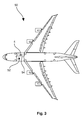
- FIG. 3 an aircraft 50, which is equipped with at least one hydraulic system 52, at the pipes 54 at least one device according to the invention for pipe rupture protection is arranged.
- a test closure 56 is shown with a bevelled and rotatably mounted closure body 58 which can be brought by rotation in an open position and a closed position.
- This principle corresponds to that in Fig. 1 shown test closure 34.
- the other special feature is a slotted socket 60, which protects an operator 62 of the test closure 56 against unauthorized or careless operation. By using a suitable tool, the operator 62 can be engaged and the test latch 56 actuated.
- test closure 64 is in Fig. 4b shown having a depressible closure body 66.
- An operator 68 in the form of a button or the like serves to actuate the test closure 64.
- FIG. 4c an additional test closure 70 shown, which rotates by rotation over a curved milled recess 72 in which a pin 74 engages in the axial direction, a closure body 76.
Landscapes
- Engineering & Computer Science (AREA)
- General Engineering & Computer Science (AREA)
- Mechanical Engineering (AREA)
- Physics & Mathematics (AREA)
- General Physics & Mathematics (AREA)
- Automation & Control Theory (AREA)
- Investigating Strength Of Materials By Application Of Mechanical Stress (AREA)
- Testing Of Devices, Machine Parts, Or Other Structures Thereof (AREA)
- Check Valves (AREA)
Description
- Die Erfindung betrifft eine Vorrichtung zur Rohrbruchsicherung, ein Verfahren zum Prüfen einer Vorrichtung zur Rohrbruchsicherung, eine Verwendung einer derartigen Vorrichtung zur Rohrbruchsicherung sowie ein Flugzeug mit mindestens einer Vorrichtung zur Rohrbruchsicherung, die dazu geeignet ist, das erfindungsgemäße Verfahren durchzuführen.
- In einer Reihe von Geräten und Systemen, in denen Fluid durchströmte Rohre angeordnet sind, werden häufig sogenannte Rohrbruchsicherungen eingesetzt. Diese sind sowohl in häuslichen Anwendungen, wie etwa Waschmaschinen oder Geschirrspülern, als auch in technisch anspruchsvollen Hydrauliksystemen von Flugzeugen bekannt. Dort werden sie auch mit dem Begriff "hydraulic fuse" bezeichnet. Ihr Zweck ist, im Fall eines Rohrbruchs zu verhindern, dass Fluid vollständig aus einer Bruchstelle ausläuft. Im Falle der Verwendung innerhalb eines Hydrauliksystems in einem Flugzeug soll ferner durch eine derartige Rohrbruchsicherung sichergestellt werden, dass sämtliche Verbraucher, die physikalisch vor der Rohrbruchsicherung angeordnet sind, durch automatisches Verschließen eines defekten Rohrzweiges oder dergleichen weiter mit Hydraulikflüssigkeit versorgt werden können.
-
US 3 424 196 offenbart ein Strömungsregelventil mit einem linear bewegbar gelagerten Kolben, der über eine Feder in einer Ausgangsstellung gehalten wird, eine Stirnfläche mit einer Durchgangsbohrung und Seitenflächen mit Durchgangsbohrungen aufweist. Deren Anordnung und Dimensionierung können unterschiedliche Differenzdrücke auf den Kolben bewirken, die zur Verschiebung des Kolbens und damit zur variablen Abdeckung der Einlassöffnungen führen, so dass der Volumenstrom durch das Strömungsregelventil beeinflusst wird. - Derartige Rohrbruchsicherungen weisen üblicherweise ein internes Schließelement auf, das bei Überschreiten eines definierten Volumenstroms automatisch in eine Schließstellung gerät und somit einen weiteren Fluidverlust stoppt. Speziell beim Einsatz in Flugzeugen und in anderen sicherheitsrelevanten Systemen ergibt sich jedoch das Problem, dass derartige Rohrbruchsicherungen im eingebauten Zustand im Hydrauliksystem (in situ) nicht überprüft werden können. Unter normalen Bedingungen kann kein Volumenstrom hergestellt werden, der die Rohrbruchsicherung zum Schließen bringt.
- Dementsprechend könnte es als Aufgabe angesehen werden, diesen oben beschriebenen Nachteil zu reduzieren oder gänzlich zu eliminieren. Die Aufgabe der Erfindung könnte daher besonders darin liegen, eine Vorrichtung zur Rohrbruchsicherung vorzuschlagen, bei der eine Sicherheitsüberprüfung im eingebauten Zustand ermöglicht wird, ohne den Volumenstrom für das betreffende Fluid durchströmte System über ein zulässiges Maximum zu erhöhen.
- Die Erfindung löst die Aufgabe durch eine Vorrichtung zur Rohrbruchsicherung, die ein Gehäuse mit einem Zulauf und einem Ablauf, mit einem bewegbar in dem Gehäuse gelagerten Schließelement mit einer zum Zulauf hin gerichteten Stirnfläche und einer zum Ablauf hin gerichteten Schließfläche, mit mindestens zwei Strömungskanälen, die sich vom Zulauf zum Ablauf hin erstrecken, mit mindestens einer in den Strömungskanälen angeordneten Blende zum Erzeugen eines Druckabfalls eines vom Zulauf zum Ablauf strömenden Fluids und mit mindestens einem zwischen dem Ablauf und dem Schließelement angeordnetem Rückhalteelement aufweist. Gemäß einem ersten Aspekt der Erfindung weist eine derartige Vorrichtung ferner mindestens einen Prüfverschluss auf, der mindestens einen der Strömungskanäle verschließt, so dass die resultierende Strömungsgeschwindigkeit in den verbleibenden Strömungskanälen erhöht wird, der Druckabfall über der Blende folglich steigt und dadurch ein Bewegen des Schließelements in eine Schließstellung verursacht wird.
- Die grundsätzliche Funktionsweise einer derartigen Vorrichtung wird im Folgenden mit anderen Worten beschrieben. Die erfindungsgemäße Vorrichtung zur Rohrbruchsicherung wird mit einer Rohrleitung in Serie geschaltet, so dass im Normalfall das entsprechende Fluid lediglich ungehindert durch die Vorrichtung strömt. In einem Gehäuse der Vorrichtung, das einen Zulauf und einen Ablauf für das Fluid aufweist, ist ein bewegbar gelagertes Schließelement angeordnet. Das Schließelement weist eine Stirnseite auf, die zum Zulauf hin zeigt. Das Schließelement weist ferner eine Schließfläche auf, die zum Ablauf zeigt. Ein durch den Zulauf in das Gehäuse strömendes Fluid strömt über die mindestens zwei Strömungskanäle um den Schließkörper herum zum Ablauf hin und tritt dort wieder aus. In einem Bereich zwischen dem Schließelement und dem Ablauf ist mindestens eine Blende angeordnet, durch die das Fluid strömen muss. Hierbei wird aufgrund des erhöhten Strömungswiderstands ein Druckabfall erzeugt. Dieser Druckabfall ist im Wesentlichen quadratisch von dem Volumenstrom des Fluids abhängig. Der am Zulauf anliegende Druck des Fluids wirkt auf die Stirnfläche des Schließelements und der am Ablauf anliegende Druck hinter der bereits durchströmten Blende wirkt auf die Schließfläche des Schließelements in der entgegengesetzten Richtung. Zusätzlich wirkt die Kraft eines Rückhalteelements auf die Schließfläche, die ebenfalls zum Zulauf hin bzw. zur Stirnfläche des Schließelements hin gerichtet ist.
- Im Normalfall, d.h. bei einem Fluidvolumenstrom innerhalb des normalen Betriebsbereichs, wirkt ein Kräfteüberschuss auf die Schließfläche, so dass die erfindungsgemäße Vorrichtung geöffnet bleibt. Die Kraft des Rückhalteelements ist derart ausgelegt, dass sich dieser Kräfteüberschuss bei Erreichen eines vorgegebenen Maximalvolumenstroms aufhebt und die auf die Stirnfläche des Schließelements wirkende Kraft der auf die Schließfläche wirkenden Kraft entspricht oder geringfügig übersteigt. Daraus resultiert eine Bewegung des Schließelements in eine Schließstellung.
- Der Kräfteüberschuss auf der Stirnfläche kann dadurch begründet werden, dass, wie vorangehend bereits erwähnt, der Druckabfall über der Blende zwischen der Schließfläche und dem Ablauf im Wesentlichen quadratisch vom Volumenstrom abhängt. Mit zunehmendem Volumenstrom steigt daher die resultierende Druckdifferenz zwischen dem Zulaufdruck und dem Ablaufdruck, so dass der Zulaufdruck ab einem bestimmten Volumenstrom ausreicht, das Schließelement gegenüber der im Verhältnis immer kleiner werdenden auf die Schließfläche wirkenden rückstellenden Kraft zur Schließstellung hin zu bewegen.
- Die Anzahl der Strömungskanäle innerhalb der erfindungsgemäßen Vorrichtung ist weder streng vorgegeben noch limitiert. Es kann jedoch durch fertigungstechnische Vereinfachungen sinnvoll sein, beispielsweise zwei oder vier Strömungskanäle zu verwenden. Es sind selbstverständlich auch drei, fünf, sechs oder mehr Strömungskanäle möglich, die bei Bedarf mit mehr als einem Prüfverschluss kombiniert werden können. Bei der exemplarischen Verwendung zweier Strömungskanäle könnte durch Verschließen eines der Strömungskanäle die Strömungsgeschwindigkeit in dem verbleibenden Strömungskanal verdoppelt und dadurch der resultierende Druckabfall über die Blende im Wesentlichen vervierfacht werden. Bei entsprechendem Fluidvolumenstrom zwischen Zulauf und Ablauf könnte bereits ausreichen, einen Kräfteüberschuss auf der Stirnfläche zu erzeugen und das Schließelement in seine Schließstellung zu bewegen.
- Die erfindungsgemäße Vorrichtung zeichnet sich gegenüber den herkömmlichen Vorrichtungen im Stand der Technik dadurch aus, dass ein Prüfverschluss in dem Gehäuse angeordnet ist, der mindestens einen Strömungskanal verschließen kann, um den resultierenden Volumenstrom bzw. die Strömungsgeschwindigkeit in den restlichen Strömungskanälen zu erhöhen. Aufgrund des Zusammenhangs zwischen der Strömungsgeschwindigkeit und dem Druckabfall resultiert die Schließung eines Strömungskanals in einem deutlich erhöhten Druckabfall über der Blende zwischen dem Zulauf und dem Ablauf und führt zum Erreichen eines Kräfteüberschusses auf der Stirnfläche des Schließelements, so dass sich das Schließelement in seine Schließstellung bewegt. Dies bedeutet, dass durch Schließen des Prüfverschlusses ein Zustand innerhalb der erfindungsgemäßen Vorrichtung erreicht wird, der ein Schließen der erfindungsgemäßen Vorrichtung veranlasst.
- Diese konstruktiv einfache Lösung ist ein sehr effektiver Weg, um die Funktionsweise einer Vorrichtung zur Rohrbruchsicherung in situ überprüfen zu können, ohne dass deren Ausbau oder teilweise Demontage erforderlich ist. Dies erspart dem Betreiber einer sicherheitsrelevanten Anlage, dem Betreiber eines Flugzeugs mit mindestens einem sicherheitsrelevanten Hydrauliksystem oder anderen Systemen deutliche Wartungskosten, ohne dass die Komplexität des Systems oder der Anlage gesteigert werden muss.
- Um zu verhindern, dass bereits bei kleinen Volumenstromspitzen aufgrund eventueller dynamischer Effekte beim raschen Schließen oder Öffnen von Ventilen oder dergleichen eine kurzzeitige Schließung der erfindungsgemäßen Vorrichtung erfolgt, kann das Schließelement in einem Buchsenabschnitt innerhalb des Gehäuses bewegbar gelagert werden, so dass zur Bewegung des Schließelements ausreichend Fluid in den Buchsenabschnitt zur Erhaltung der Volumenkonstanz nachströmen muss. Dieses Nachströmen von Fluid kann durch einen stirnseitig des Schließelements angeordneten Deckel für den Buchsenabschnitt mit einer darin integrierten und zum Zulauf gerichteten Drossel begrenzt werden, so dass die Auslenkung des Schließelements gedämpft wird. Sobald der Maximalvolumenstrom erreicht oder überschritten wird und auf der Stirnfläche ein Kräfteüberschuss vorliegt, drängt das Schließelement in seine Schließstellung, wobei sich der entstehende Hohlraum zwischen dem Schließelement und dem Deckel langsam mit Fluid anfüllt und dabei die Geschwindigkeit des Schließelements begrenzt. Auftretende Druck- bzw. Durchflussspitzen können dadurch vollständig abgefangen werden.
- Es ist denkbar, bei mehreren Strömungskanälen mehrere Prüfverschlüsse vorzusehen, so dass etwa zwei Prüfverschlüsse oder mehr geschlossen werden müssen, um einen Funktionstest durchführen zu können.
- In einer besonders vorteilhaften Weiterbildung der erfindungsgemäßen Vorrichtung ist der Prüfverschluss bewegbar an dem Gehäuse angeordnet, so dass durch Bewegen des Prüfverschlusses in eine Schließposition oder in eine Öffnungsposition ein Schließen oder ein Öffnen eines Strömungskanals erfolgt.
- Der Prüfverschluss könnte in einer besonders vorteilhaften Weiterbildung der erfindungsgemäßen Vorrichtung drehbar gelagert sein und eine Verschlussfläche aufweisen, die in einer Öffnungsposition mit einer umgebenden Wandung des betreffenden Strömungskanals bündig abschließt und in einer Schließposition den betreffenden Strömungskanal verschließt. Die Schließposition könnte ausgehend von der Öffnungsposition etwa durch Drehen des Prüfverschlusses um 180° erreicht werden.
- Weiterhin könnte es in einer günstigen Ausführungsform der erfindungsgemäßen Vorrichtung von Vorteil sein, dass der Prüfverschluss longitudinal in den betreffenden Strömungskanal auslenkbar ist, so dass beispielsweise durch Drücken oder Ziehen ein Schließen und Öffnen des betreffenden Strömungskanals erfolgen kann. Der Prüfverschluss könnte dabei federnd gelagert sein und bei Erreichen der Schließstellung des Schließelements wieder losgelassen werden.
- In einer besonders vorteilhaften Weiterbildung der erfindungsgemäßen Vorrichtung ist der Prüfverschluss ausgestaltet, dass in seiner Schließposition eine Warnfarbe deutlich sichtbar wird und vor einem Betrieb der erfindungsgemäßen Vorrichtung bei geschlossenem Prüfverschluss gewarnt wird.
- Es ist auch denkbar dass der Prüfverschluss in unbedrucktem Zustand betätigt und verriegelt wird, etwa aus Sicherheitsgründen oder weil die Betätigungskräfte unter Druck zu hoch wären. Nach Beendigung des Tests müsste die Vorrichtung von Hand zurückgestellt werden. Das dazu nötige Spezialwerkzeug könnte beispielsweise in der Luftfahrt wie üblich mit einer langen roten Warnfahne versehen werden.
- Weiterhin könnte es besonders vorteilhaft sein, dass der Prüfverschluss mechanisch derart ausgestaltet ist, dass er nur über ein spezielles Werkzeug in eine Schließposition gebracht werden kann und das Spezialwerkzeug auch nur in einer Öffnungsposition wieder von dem Prüfverschluss abziehbar ist. Hierdurch kann besonders effektiv ein versehentliches Schließen des Prüfverschlusses verhindert werden.
- Weiterhin wird die Aufgabe durch ein Verfahren zum Prüfen einer Vorrichtung zur Rohrbruchsicherung gelöst, wobei das Verfahren die Schritte des Betreibens des übergeordneten Systems, des Schließens mindestens eines Prüfverschlusses, das Abschalten des übergeordneten Systems bei Erreichen der Schließstellung des Schließelements und ein anschließendes optionales Betreiben des übergeordneten Systems umfasst.
- Weiterhin wird die Aufgabe gelöst durch eine Verwendung einer Vorrichtung zur Rohrbruchsicherung in einem Flugzeug, sowie durch ein Flugzeug mit mindestens einem Hydrauliksystem und mindestens einer darin befindlichen erfindungsgemäßen Vorrichtung zur Rohrbruchsicherung.
- Weitere Merkmale, Vorteile und Anwendungsmöglichkeiten der vorliegenden Erfindung ergeben sich aus der nachfolgenden Beschreibung der Ausführungsbeispiele und den Figuren. Dabei bilden alle beschriebenen und/oder bildlich dargestellten Merkmale für sich und in beliebiger Kombination den Gegenstand der Erfindung auch unabhängig von ihrer Zusammensetzung in den einzelnen Ansprüchen oder deren Rückbeziehungen. In den Figuren stehen weiterhin gleiche Bezugszeichen für gleiche oder ähnliche Objekte.
-
Fig. 1 zeigt eine erfindungsgemäße Vorrichtung in einer seitlichen Schnittansicht. -
Fig. 2 zeigt das erfindungsgemäße Verfahren in einer schematischen Blockansicht. -
Fig. 3 zeigt ein Flugzeug mit mindestens einem Hydrauliksystem und mindestens einer darin angeordneten erfindungsgemäßen Vorrichtung zur Rohrbruchsicherung. -
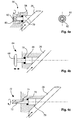
Fig. 4a bis 4c zeigen verschiedene exemplarische Prüfverschlüsse. - In
Fig. 1 wird in einem seitlichen Schnitt eine erfindungsgemäße Vorrichtung zur Rohrbruchsicherung 2 gezeigt, die ein Gehäuse 4 mit einem Zulauf 6 und einem Ablauf 8 aufweist, sowie ein Schließelement 10, das in einem Buchsenabschnitt 12 bewegbar gelagert ist und eine Stirnfläche 14 und eine Schließfläche 16 aufweist. Ferner ist in dem Gehäuse 4 ein Rückhalteelement 18 angeordnet, das über eine Feder 20 an dem Gehäuse 4 im Bereich des Ablaufs 8 abgestützt ist. Zwischen dem Schließelement 10 und dem Rückhalteelement 18 sind mehrere Blenden 22 angeordnet, die einen Druckabfall eines von dem Zulauf 6 zum Ablauf 8 strömenden Fluids verursachen. - Zwischen dem Zulauf 6 und den Blenden 22 sind in dieser Darstellung zwei Strömungskanäle 24 und 26 ersichtlich, es können allerdings auch mehr Strömungskanäle in dem Gehäuse 4 angeordnet werden. Strömt Fluid durch den Zulauf 6 in die beiden Strömungskanäle 24 und 26, gerät das Fluid durch die Blenden 22 und erfährt hierdurch einen Druckverlust. Der Druckverlust steigt im Wesentlichen quadratisch mit der Strömungsgeschwindigkeit innerhalb der Strömungskanäle 24 und 26 an, so dass beispielsweise bei einem sich verdoppelnden Volumenstrom ein viermal so hoher Druckabfall über die Blenden 22 zu erwarten ist.
- Das Schließelement 10 kann sich in der Zeichnungsebene nach rechts zum Ablauf 8 hin bewegen, wobei es bei Erreichen von Kanten 28 eine Schließstellung erreicht, in der die Blenden 22 verschlossen werden, so dass die Fluidströmung zwischen dem Zulauf 6 und dem Ablauf 8 vollständig unterbrochen wird. Die Bewegung des Schließelements 10 in diese Schließstellung wird bei zunehmender Druckdifferenz zwischen einem am Zulauf 6 liegenden Druck und einem am Ablauf 8 liegenden Druck verursacht. Übersteigt die auf die Stirnfläche 14 des Schließelements 10 wirkende Kraft die rücktreibende und auf die Schließfläche 16 wirkende Kraft, die sich aus dem Druck am Ablauf 8 und der Feder 20 ergibt, drängt das Schließelement 10 in seine Schließstellung. Diese Stellung kann erst dann wieder verlassen werden, wenn der Fluiddruck am Zulauf 6 unterbrochen wird.
- Zum Ausgleichen von Druck- bzw. Durchflussspitzen, die sich etwa durch schnelle Öffnungs- oder Schließbewegungen von Ventilen oder dergleichen in einem Hydrauliksystem ergeben, ist ein mit einer Drossel 30 versehener Deckel 32 an dem Buchsenabschnitt 12 angeordnet. Drängt das Schließelement 10 in seine Schließstellung muss sich der zwischen dem Schließelement 10 und dem Deckel 32 befindliche Hohlraum zur Erhaltung einer Volumenkonstanz mit Fluid auffüllen, um eine Bewegung des Schließelements 10 zu erlauben. Durch eine entsprechende Auslegung der Drossel 30 kann dadurch besonders einfach eine Dämpfungswirkung auf die Bewegung des Schließelements 10 erreicht werden, die im Idealfall Druck- bzw. Durchflussspitzen am Zulauf 6 vollständig ausgleichen kann.
- Damit eine Prüfung der erfindungsgemäßen Vorrichtung ermöglicht wird, ist an dem Gehäuse 4 ein Prüfverschluss 34 angeordnet, der den oberen Strömungskanal 26 verschließen kann. Hierfür weist der Prüfverschluss 34 eine Verschlussfläche 36 auf, der in einer Öffnungsposition des Prüfverschlusses mit einer Wandung 38 des Strömungskanals vollständig bündig ist. Wird der Prüfverschluss 34 in dieser Öffnungsposition etwa um 180° um dessen eigene Achse gedreht, verdreht sich die Verschlussfläche 36 bei entsprechender geometrischer Gestaltung des Prüfverschlusses derart, dass der Strömungskanal 26 vollständig geschlossen wird.
- Der Strömungskanal 26 könnte hierfür einen Abschnitt aufweisen, dessen Mittelachse mit der Längsachse der erfindungsgemäßen Vorrichtung einen Winkel von 45° einschließt, so dass auch die Verschlussfläche 36 eine 45°-Neigung besitzt. Um 180° verdreht erstreckt sich die Verschlussfläche 36 senkrecht zur Wandung 38 und ragt dann über den gesamten Querschnitt des betreffenden Strömungskanals 26.
- Wird der Prüfverschluss 34 in eine Schließstellung gebracht, endet der Volumenstrom in dem oberen Strömungskanal 26, so dass das gesamte einströmende Fluid durch den unteren Strömungskanal 24 tritt. Hier wird angenommen, dass die erfindungsgemäße Vorrichtung 2 lediglich zwei Strömungskanäle 24 und 26 aufweist. Der Druckverlust an den Blenden 22 ist aufgrund der nun doppelten Strömungsgeschwindigkeit auf ein Vierfaches angestiegen. Dieser deutlich höhere Druckverlust könnte bei entsprechender Auslegung der Federkraft dazu ausreichen, auf der Stirnfläche 14 des Schließelements 10 einen Kräfteüberschuss aufzubauen, der zum Bewegen des Schließelements 10 in seine Schließposition führt.
- Die gezeigte Darstellung ist lediglich exemplarisch zu verstehen, so dass auch mehr Strömungskanäle in dem Gehäuse 4 angeordnet werden können. Dazu können auch Prüfverschlüsse in ausreichender Anzahl über die Strömungskanäle verteilt werden, die auch auf einem anderen Funktionsprinzip beruhen könnten. So wären auch Prüfverschlüsse denkbar, die in einen entsprechenden Strömungskanal 22 hineingedrückt werden.
-
Fig. 2 zeigt exemplarisch ein erfindungsgemäßes Verfahren in einer schematischen Blockbilddarstellung. Nach dem Einleiten 40 des Betriebs eines übergeordneten Systems, beispielsweise eines Hydrauliksystems, werden nacheinander sämtliche vorhandenen Prüfverschlüsse 34 geschlossen 42 und die Reaktion sämtlicher in dem übergeordneten System angeordneter erfindungsgemäßer Vorrichtungen 2 geprüft 44. Nachdem dieser Test abgeschlossen ist, wird der Betrieb des übergeordneten Systems unterbrochen 46, so dass sich jeweils das Schließelement 10 jeder der erfindungsgemäßen Vorrichtungen 2 wieder zum Zulauf 6 hin bewegt. Anschließend kann ein erneutes Einleiten 48 des Betriebs des übergeordneten Systems erfolgen. - Weiterhin zeigt
Fig. 3 ein Flugzeug 50, das mit mindestens einem Hydrauliksystem 52 ausgerüstet ist, an dessen Rohrleitungen 54 mindestens eine erfindungsgemäße Vorrichtung zur Rohrbruchsicherung angeordnet ist. - In
Fig. 4a wird ein Prüfverschluss 56 mit einem abgeschrägten und rotierbar gelagerten Verschlusskörper 58 gezeigt, der durch eine Rotation in eine Öffnungsposition und eine Verschlussposition gebracht werden kann. Dieses Prinzip entspricht dem inFig. 1 gezeigten Prüfverschluss 34. Die weitere Besonderheit liegt in einer geschlitzten Buchse 60, die ein Bedienende 62 des Prüfverschlusses 56 vor unbefugter oder unbedachter Bedienung schützt. Durch Verwenden eines geeigneten Werkzeugs kann das Bedienende 62 in Eingriff genommen und der Prüfverschluss 56 betätigt werden. - Ein weiterer möglicher Prüfverschluss 64 wird in
Fig. 4b gezeigt, der einen eindrückbaren Verschlusskörper 66 aufweist. Ein Bedienende 68 in Form eines Knopfs oder dergleichen dient zum Betätigen des Prüfverschlusses 64. - Weiterhin wird in
Fig. 4c ein zusätzlicher Prüfverschluss 70 dargestellt, der durch Rotation über eine gekrümmte Einfräsung 72, in der ein Stift 74 eingreift, in axialer Richtung einen Verschlusskörper 76 auslenkt. - Sämtliche dieser Beispiele sind lediglich exemplarisch zu verstehen. Es versteht sich, dass zur Abdichtung entsprechende Dichtungsringe 78 oder dergleichen eingesetzt werden.
- Ergänzend ist darauf hinzuweisen, dass "aufweisend" keine anderen Elemente oder Schritte ausschließt und "eine" oder "ein" keine Vielzahl ausschließt. Ferner sei darauf hingewiesen, dass Merkmale oder Schritte, die mit Verweis auf eines der obigen Ausführungsbeispiele beschrieben worden sind, auch in Kombination mit anderen Merkmalen oder Schritten anderer oben beschriebener Ausführungsbeispiele verwendet werden können. Bezugszeichen in den Ansprüchen sind nicht als Einschränkung anzusehen.
-
- 2
- erfindungsgemäße Vorrichtung
- 4
- Gehäuse
- 6
- Zulauf
- 8
- Ablauf
- 10
- Schließelement
- 12
- Buchsenabschnitt
- 14
- Stirnfläche
- 16
- Schließfläche
- 18
- Rückhalteelement
- 20
- Feder
- 22
- Blende
- 24
- Strömungskanal
- 26
- Strömungskanal
- 28
- Kante
- 30
- Drossel
- 32
- Deckel
- 34
- Prüfverschluss
- 36
- Verschlussfläche
- 38
- Wandung
- 40
- Einleiten Betrieb
- 42
- Schließen Prüfverschluss
- 44
- Prüfen der erfindungsgemäßen Vorrichtung
- 46
- Unterbrechen Betrieb
- 48
- Einleiten Betrieb
- 50
- Flugzeug
- 52
- Hydrauliksystem
- 54
- Rohrleitung
- 56
- Prüfverschluss
- 58
- Verschlusskörper
- 60
- Buchse
- 62
- Bedienende
- 64
- Prüfverschluss
- 66
- Verschlusskörper
- 68
- Bedienende
- 70
- Prüfverschluss
- 72
- Einfräsung
- 74
- Stift
- 76
- Verschlusskörper
- 78
- Dichtung
Claims (11)
- Vorrichtung (2) zur Rohrbruchsicherung, aufweisend:- ein Gehäuse (4) mit einem Zulauf (6) und einem Ablauf (8);- ein bewegbar in dem Gehäuse (4) gelagertes Schließelement (10) mit einer zum Zulauf (6) gerichteten Stirnfläche (14) und einer zum Ablauf (8) gerichteten Schließfläche (16);- mindestens zwei Strömungskanälen (24, 26), die sich vom Zulauf (6) zum Ablauf (8) hin erstrecken;- mindestens eine in den Strömungskanälen (24, 26) angeordnete Blende (22) zum Erzeugen eines Druckabfalls eines vom Zulauf (6) zum Ablauf (8) strömenden Fluids; und- mindestens ein zwischen dem Ablauf (8) und dem Schließelement (10) angeordnetes Rückhalteelement (18);wobei ein an dem Zulauf (6) anliegender Zulaufdruck des Fluids auf die Stirnfläche (14) des Schließelements (10) wirkt und ein an dem Ablauf (8) anliegender Ablaufdruck des Fluids auf die Schließfläche (16) des Schließelements (10) wirkt;
wobei das Rückhalteelement (18) derart dimensioniert ist, dass sich das Schließelement (10) bei einer vorbestimmten Mindestdifferenz zwischen Zulaufdruck und Ablaufdruck gegen eine Rückhaltekraft des Rückhalteelements (18) zum Ablauf (8) in eine Schließstellung bewegt;
wobei die Vorrichtung (2) ferner mindestens einen Prüfverschluss (34, 56, 64, 70) aufweist, der mindestens einen der Strömungskanäle (24, 26) verschließt, so dass die Strömungsgeschwindigkeit in den verbleibenden Strömungskanälen (24, 26) erhöht wird, der Druckabfall über die Blende (22) steigt und dadurch ein Bewegen des Schließelements (10) in die Schließstellung verursacht wird. - Vorrichtung (2) nach Anspruch 1,
wobei das Schließelement (10) in einem durch einen Deckel (32) geschlossenen Buchsenabschnitt (12) des Gehäuses (4) bewegbar gelagert ist,
wobei der Deckel (32) eine Drossel (30) zum gedrosselten Durchströmen von Fluid aufweist. - Vorrichtung (2) nach Anspruch 1 oder 2,
wobei der Prüfverschluss (34, 56, 64, 70) bewegbar an dem Gehäuse (4) angeordnet ist und durch Bewegen des Prüfverschlusses (34, 56, 64, 70) in eine Schließposition oder in eine Öffnungsposition ein Schließen oder ein Öffnen eines Strömungskanals (24, 26) erfolgt. - Vorrichtung (2) nach einem der vorhergehenden Ansprüche,
wobei der Prüfverschluss (34, 56, 64, 70) drehbar gelagert ist und eine Verschlussfläche (36) aufweist, die in einer Öffnungsposition mit einer umgebenden Wandung des betreffenden Strömungskanals (24, 26) bündig abschließt und in einer Schließposition den betreffenden Strömungskanal (24, 26) verschließt. - Vorrichtung (2) nach einem der Ansprüche 1 bis 3,
wobei der Prüfverschluss (34, 56, 64, 70) longitudinal in den betreffenden Strömungskanal (24, 26) zum Schließen auslenkbar ist. - Vorrichtung (2) nach einem der vorhergehenden Ansprüche,
wobei der Prüfverschluss (34, 56, 64, 70) federnd gelagert ist und ohne Einwirkung von außen selbständig von seiner Schließposition in seine Öffnungsposition zurückkehrt. - Vorrichtung (2) nach einem der vorhergehenden Ansprüche,
wobei der Prüfverschluss (34, 56, 64, 70) derart ausgestaltet ist, in einer Schließposition eine Warnfarbe deutlich sichtbar zu zeigen. - Vorrichtung (2) nach einem der vorhergehenden Ansprüche,
wobei der Prüfverschluss (34, 56, 64, 70) derart ausgestaltet ist, dass er nur über ein spezielles Werkzeug in eine Schließposition gebracht werden kann und das Spezialwerkzeug auch nur in einer Öffnungsposition wieder von dem Prüfverschluss (34, 56, 64, 70) abziehbar ist. - Verfahren zum Prüfen einer oder mehrerer Vorrichtungen (2) zur Rohrbruchsicherung , nach einem der Ansprüche 1 bis 8, in einem Fluid durchströmten System, aufweisend die Schritte:- dem Einleiten des Betriebs des Systems;- Schließen sämtlicher Prüfverschlüsse (34. 56. 64. 70):- Prüfen der Reaktion der Vorrichtungen (2):- Unterbrechen des Betriebs des Systems.
- Verwendung einer Vorrichtung (2) nach einem der Ansprüche 1 bis 8 zur Rohrbruchsicherung in einem Fluid durchströmten System (52) eines Flugzeugs (50).
- Flugzeug (50) mit mindestens einem Hydrauliksystem (52), mindestens einer Hydraulikrohrleitung (54) und mindestens einer daran befindlichen Vorrichtung (2) zur Rohrbruchsicherung, das dazu geeignet ist, eine in situ Funktionsprüfung durchzuführen, aufweisend:- ein Gehäuse (4) mit einem Zulauf (6) und einem Ablauf (8);- ein bewegbar in dem Gehäuse (4) gelagertes Schließelement (10) mit einer zum Zulauf (6) gerichteten Stirnfläche und einer zum Ablauf (8) gerichteten Schließfläche (16);- mindestens zwei Strömungskanälen (24, 26), die sich vom Zulauf (6) zum Ablauf (8) hin erstrecken;- mindestens eine in den Strömungskanälen (24, 26) angeordnete Blende (22) zum Erzeugen eines Druckabfalls eines vom Zulauf (6) zum Ablauf (8) strömenden Fluids; und- mindestens ein zwischen dem Ablauf (8) und dem Schließelement (10) angeordnetes Rückhalteelement (18);wobei ein an dem Zulauf (6) anliegender Zulaufdruck des Fluids auf die Stirnfläche (14) des Schließelements (10) wirkt und ein an dem Ablauf (8) anliegender Ablaufdruck des Fluids auf die Schließfläche (16) des Schließelements (10) wirkt;
wobei das Rückhalteelement (18) derart dimensioniert ist, dass sich das Schließelement (10) bei einer vorbestimmten Mindestdifferenz zwischen Zulaufdruck und Ablaufdruck gegen eine Rückhaltekraft des Rückhalteelements (18) zum Ablauf (8) in eine Schließstellung bewegt;
wobei die Vorrichtung (2) ferner mindestens einen Prüfverschluss (34, 56, 64, 70) aufweist, der mindestens einen der Strömungskanäle (24, 26) verschließt, so dass die Strömungsgeschwindigkeit in den verbleibenden Strömungskanälen (24, 26) erhöht wird, der Druckabfall über die Blende (22) steigt und dadurch ein Bewegen des Schließelements (10) in die Schließstellung verursacht wird.
Applications Claiming Priority (3)
| Application Number | Priority Date | Filing Date | Title |
|---|---|---|---|
| US23674609P | 2009-08-25 | 2009-08-25 | |
| DE200910038780 DE102009038780B4 (de) | 2009-08-25 | 2009-08-25 | Vorrichtung zur Rohrbruchsicherung |
| PCT/EP2010/062332 WO2011023694A1 (de) | 2009-08-25 | 2010-08-24 | Vorrichtung zur rohrbruchsicherung |
Publications (3)
| Publication Number | Publication Date |
|---|---|
| EP2470814A1 EP2470814A1 (de) | 2012-07-04 |
| EP2470814B1 true EP2470814B1 (de) | 2013-11-06 |
| EP2470814B8 EP2470814B8 (de) | 2013-12-25 |
Family
ID=43525006
Family Applications (1)
| Application Number | Title | Priority Date | Filing Date |
|---|---|---|---|
| EP20100747193 Active EP2470814B8 (de) | 2009-08-25 | 2010-08-24 | Vorrichtung zur rohrbruchsicherung |
Country Status (5)
| Country | Link |
|---|---|
| US (1) | US8739825B2 (de) |
| EP (1) | EP2470814B8 (de) |
| CN (1) | CN102575787B (de) |
| DE (1) | DE102009038780B4 (de) |
| WO (1) | WO2011023694A1 (de) |
Families Citing this family (7)
| Publication number | Priority date | Publication date | Assignee | Title |
|---|---|---|---|---|
| CN103032615B (zh) * | 2012-12-06 | 2016-01-27 | 武汉大禹阀门股份有限公司 | 爆管限流阀 |
| CN104235489A (zh) * | 2013-06-08 | 2014-12-24 | 陈欢娟 | 一种限流节水器 |
| DE102016115360B4 (de) * | 2016-08-18 | 2022-05-12 | Mesa Parts GmbH | Überströmventil zum zumindest teilweisen Verschließen und Öffnen eines Fluidleitungssystems |
| WO2018225102A1 (en) * | 2017-06-09 | 2018-12-13 | Buffo Salvatore | Safety valve for hydraulic systems |
| US11103102B2 (en) | 2019-07-09 | 2021-08-31 | B/E Aerospace, Inc. | Vent valve flow fuse |
| CN114754156B (zh) * | 2021-01-12 | 2023-02-14 | 宁波方太厨具有限公司 | 可调式稳流阀 |
| US11566715B1 (en) * | 2021-07-06 | 2023-01-31 | Saudi Arabian Oil Company | Preventing an over pressure condition with a mechanical shutdown valve |
Family Cites Families (14)
| Publication number | Priority date | Publication date | Assignee | Title |
|---|---|---|---|---|
| US2411392A (en) * | 1943-06-26 | 1946-11-19 | Cons Vultee Aircraft Corp | Control mechanism for hydraulically operated devices |
| US3357448A (en) * | 1965-06-14 | 1967-12-12 | Micro Pump Corp | Constant flow valve |
| US3424196A (en) * | 1966-06-01 | 1969-01-28 | Deltrol Corp | Flow regulating valve |
| US3424496A (en) * | 1967-02-16 | 1969-01-28 | Wendell Arthur Prough | Vehicle passenger safety devices |
| US3494375A (en) * | 1967-06-29 | 1970-02-10 | Componetrol | Hydraulic fuse with plural flow paths |
| US4383549A (en) * | 1981-04-22 | 1983-05-17 | Imperial Clevite Inc. | Adjustable velocity fuse for hydraulic line |
| SE435094B (sv) | 1982-02-25 | 1984-09-03 | Regioninvest I Norr Ab | Ledningsbrottventil for tryckledning eller -slang med omgivande skyddsledning eller -slang |
| US4605039A (en) * | 1984-10-04 | 1986-08-12 | Stewart-Warner Corporation | Runaway protective fuse valve |
| US5099875A (en) * | 1991-02-06 | 1992-03-31 | Moog Controls, Inc. | Fluid flow regulator |
| DE19510586A1 (de) | 1995-03-23 | 1996-09-26 | Rexroth Mannesmann Gmbh | Rohrbruchsicherungsventil |
| US5799684A (en) * | 1996-05-14 | 1998-09-01 | Aeroquip Corporation | Frangible hydraulic fuse |
| US6443180B1 (en) * | 2001-03-15 | 2002-09-03 | Predator Systems Inc. | Hydraulic line adjustable velocity fuse with damping |
| CN2833289Y (zh) * | 2005-07-02 | 2006-11-01 | 吴正平 | 管路防爆安全阀 |
| CN100429442C (zh) * | 2006-12-04 | 2008-10-29 | 陈伟明 | 一种压力自动关闭阀 |
-
2009
- 2009-08-25 DE DE200910038780 patent/DE102009038780B4/de active Active
-
2010
- 2010-08-24 EP EP20100747193 patent/EP2470814B8/de active Active
- 2010-08-24 WO PCT/EP2010/062332 patent/WO2011023694A1/de not_active Ceased
- 2010-08-24 CN CN2010800381516A patent/CN102575787B/zh not_active Expired - Fee Related
-
2012
- 2012-02-24 US US13/404,278 patent/US8739825B2/en active Active
Also Published As
| Publication number | Publication date |
|---|---|
| CN102575787A (zh) | 2012-07-11 |
| DE102009038780B4 (de) | 2011-12-01 |
| WO2011023694A1 (de) | 2011-03-03 |
| US20120160347A1 (en) | 2012-06-28 |
| CN102575787B (zh) | 2013-10-30 |
| DE102009038780A8 (de) | 2011-06-01 |
| EP2470814B8 (de) | 2013-12-25 |
| DE102009038780A1 (de) | 2011-03-03 |
| US8739825B2 (en) | 2014-06-03 |
| EP2470814A1 (de) | 2012-07-04 |
Similar Documents
| Publication | Publication Date | Title |
|---|---|---|
| DE102009038780B4 (de) | Vorrichtung zur Rohrbruchsicherung | |
| EP2011928B1 (de) | Rohrtrenneranordnung | |
| DE2547912C3 (de) | Hydraulischer Unterbrecher | |
| DE3100037C2 (de) | ||
| DE2933459A1 (de) | Kugelventil mit hohlraumdruckverminderung | |
| DE102014101416A1 (de) | Ventilvorrichtung für einen hydraulischen Türschließer | |
| EP0110289B1 (de) | Ausgleichventil | |
| DE102016115360B4 (de) | Überströmventil zum zumindest teilweisen Verschließen und Öffnen eines Fluidleitungssystems | |
| CH620507A5 (de) | ||
| DE102008020975B4 (de) | Absperrhahn, insbesondere Kugelhahn | |
| DE2651758A1 (de) | Druckausgeglichenes ventil | |
| EP1508730A1 (de) | Strömungswächter zum automatischen Absperren von mit Fluid durchströmten Leitungen | |
| DE202015100368U1 (de) | Verbinder für Fluidtransportkreis und Fluidtransportkreis mit einem solchen Verbinder | |
| DE102021002519A1 (de) | Schutzvorrichtung für Batteriegehäuse | |
| DE3785877T2 (de) | Stossdämpfer und Verfahren und Vorrichtung zur Überprüfung an Ort und Stelle. | |
| DE1750053B2 (de) | Doppelrohrbruchsicherheitsventil | |
| DE69222651T2 (de) | Mehrfachsensorentlastungsventil eines bohrlochuntersuchungssystems | |
| EP1688205B1 (de) | Vorrichtung zum Kühlen von Schweisskappen | |
| DE2249601C3 (de) | Parallel-Platten-Absperrschieber | |
| DE102015109241A1 (de) | Rückstauverschluss | |
| DE102009017335A1 (de) | Vorrichtung zur Messung des Volumen- oder Massestromes eines Mediums, Maschine mit entsprechender Vorrichtung | |
| DE102005062346A1 (de) | Hydraulischer Linear-Stellantrieb | |
| DE3102828A1 (de) | Berstfolien-sicherheitsventil | |
| DE2930819A1 (de) | Vorrichtung zur verhinderung des rueckflusses von wasser von einer verbrauchsstelle in eine wasserversorgungsleitung | |
| DE102016214788A1 (de) | Steuersystem für eine Feuerlöschanlage, und Sicherheitseinrichtung |
Legal Events
| Date | Code | Title | Description |
|---|---|---|---|
| PUAI | Public reference made under article 153(3) epc to a published international application that has entered the european phase |
Free format text: ORIGINAL CODE: 0009012 |
|
| 17P | Request for examination filed |
Effective date: 20120224 |
|
| AK | Designated contracting states |
Kind code of ref document: A1 Designated state(s): AL AT BE BG CH CY CZ DE DK EE ES FI FR GB GR HR HU IE IS IT LI LT LU LV MC MK MT NL NO PL PT RO SE SI SK SM TR |
|
| DAX | Request for extension of the european patent (deleted) | ||
| GRAP | Despatch of communication of intention to grant a patent |
Free format text: ORIGINAL CODE: EPIDOSNIGR1 |
|
| INTG | Intention to grant announced |
Effective date: 20130529 |
|
| GRAS | Grant fee paid |
Free format text: ORIGINAL CODE: EPIDOSNIGR3 |
|
| GRAA | (expected) grant |
Free format text: ORIGINAL CODE: 0009210 |
|
| AK | Designated contracting states |
Kind code of ref document: B1 Designated state(s): AL AT BE BG CH CY CZ DE DK EE ES FI FR GB GR HR HU IE IS IT LI LT LU LV MC MK MT NL NO PL PT RO SE SI SK SM TR |
|
| REG | Reference to a national code |
Ref country code: GB Ref legal event code: FG4D Free format text: NOT ENGLISH |
|
| RBV | Designated contracting states (corrected) |
Designated state(s): AL AT BE BG CH CY CZ DK EE ES FI FR GB GR HR HU IE IS IT LI LT LU LV MC MK MT NL NO PL PT RO SE SI SK SM TR |
|
| REG | Reference to a national code |
Ref country code: DE Ref legal event code: R108 Ref document number: 502010005307 Country of ref document: DE |
|
| REG | Reference to a national code |
Ref country code: CH Ref legal event code: EP |
|
| RBV | Designated contracting states (corrected) |
Designated state(s): AL AT BE BG CH CY CZ DK EE ES FI FR GB GR HR HU IE IS IT LI LT LU LV MC MK MT NL NO PL PT RO SE SI SK SM TR |
|
| REG | Reference to a national code |
Ref country code: AT Ref legal event code: REF Ref document number: 639732 Country of ref document: AT Kind code of ref document: T Effective date: 20131215 |
|
| REG | Reference to a national code |
Ref country code: IE Ref legal event code: FG4D Free format text: LANGUAGE OF EP DOCUMENT: GERMAN |
|
| REG | Reference to a national code |
Ref country code: DE Ref legal event code: R108 Ref document number: 502010005307 Country of ref document: DE Effective date: 20131114 Ref country code: DE Ref legal event code: R096 Ref document number: 502010005307 Country of ref document: DE Effective date: 20140102 |
|
| REG | Reference to a national code |
Ref country code: NL Ref legal event code: VDEP Effective date: 20131106 |
|
| REG | Reference to a national code |
Ref country code: LT Ref legal event code: MG4D |
|
| PG25 | Lapsed in a contracting state [announced via postgrant information from national office to epo] |
Ref country code: FI Free format text: LAPSE BECAUSE OF FAILURE TO SUBMIT A TRANSLATION OF THE DESCRIPTION OR TO PAY THE FEE WITHIN THE PRESCRIBED TIME-LIMIT Effective date: 20131106 Ref country code: LT Free format text: LAPSE BECAUSE OF FAILURE TO SUBMIT A TRANSLATION OF THE DESCRIPTION OR TO PAY THE FEE WITHIN THE PRESCRIBED TIME-LIMIT Effective date: 20131106 Ref country code: NL Free format text: LAPSE BECAUSE OF FAILURE TO SUBMIT A TRANSLATION OF THE DESCRIPTION OR TO PAY THE FEE WITHIN THE PRESCRIBED TIME-LIMIT Effective date: 20131106 Ref country code: NO Free format text: LAPSE BECAUSE OF FAILURE TO SUBMIT A TRANSLATION OF THE DESCRIPTION OR TO PAY THE FEE WITHIN THE PRESCRIBED TIME-LIMIT Effective date: 20140206 Ref country code: SE Free format text: LAPSE BECAUSE OF FAILURE TO SUBMIT A TRANSLATION OF THE DESCRIPTION OR TO PAY THE FEE WITHIN THE PRESCRIBED TIME-LIMIT Effective date: 20131106 Ref country code: IS Free format text: LAPSE BECAUSE OF FAILURE TO SUBMIT A TRANSLATION OF THE DESCRIPTION OR TO PAY THE FEE WITHIN THE PRESCRIBED TIME-LIMIT Effective date: 20140306 Ref country code: HR Free format text: LAPSE BECAUSE OF FAILURE TO SUBMIT A TRANSLATION OF THE DESCRIPTION OR TO PAY THE FEE WITHIN THE PRESCRIBED TIME-LIMIT Effective date: 20131106 |
|
| PG25 | Lapsed in a contracting state [announced via postgrant information from national office to epo] |
Ref country code: LV Free format text: LAPSE BECAUSE OF FAILURE TO SUBMIT A TRANSLATION OF THE DESCRIPTION OR TO PAY THE FEE WITHIN THE PRESCRIBED TIME-LIMIT Effective date: 20131106 Ref country code: ES Free format text: LAPSE BECAUSE OF FAILURE TO SUBMIT A TRANSLATION OF THE DESCRIPTION OR TO PAY THE FEE WITHIN THE PRESCRIBED TIME-LIMIT Effective date: 20131106 |
|
| PG25 | Lapsed in a contracting state [announced via postgrant information from national office to epo] |
Ref country code: PT Free format text: LAPSE BECAUSE OF FAILURE TO SUBMIT A TRANSLATION OF THE DESCRIPTION OR TO PAY THE FEE WITHIN THE PRESCRIBED TIME-LIMIT Effective date: 20140306 |
|
| PG25 | Lapsed in a contracting state [announced via postgrant information from national office to epo] |
Ref country code: EE Free format text: LAPSE BECAUSE OF FAILURE TO SUBMIT A TRANSLATION OF THE DESCRIPTION OR TO PAY THE FEE WITHIN THE PRESCRIBED TIME-LIMIT Effective date: 20131106 |
|
| PG25 | Lapsed in a contracting state [announced via postgrant information from national office to epo] |
Ref country code: PL Free format text: LAPSE BECAUSE OF FAILURE TO SUBMIT A TRANSLATION OF THE DESCRIPTION OR TO PAY THE FEE WITHIN THE PRESCRIBED TIME-LIMIT Effective date: 20131106 Ref country code: CZ Free format text: LAPSE BECAUSE OF FAILURE TO SUBMIT A TRANSLATION OF THE DESCRIPTION OR TO PAY THE FEE WITHIN THE PRESCRIBED TIME-LIMIT Effective date: 20131106 Ref country code: IT Free format text: LAPSE BECAUSE OF FAILURE TO SUBMIT A TRANSLATION OF THE DESCRIPTION OR TO PAY THE FEE WITHIN THE PRESCRIBED TIME-LIMIT Effective date: 20131106 Ref country code: RO Free format text: LAPSE BECAUSE OF FAILURE TO SUBMIT A TRANSLATION OF THE DESCRIPTION OR TO PAY THE FEE WITHIN THE PRESCRIBED TIME-LIMIT Effective date: 20131106 Ref country code: SK Free format text: LAPSE BECAUSE OF FAILURE TO SUBMIT A TRANSLATION OF THE DESCRIPTION OR TO PAY THE FEE WITHIN THE PRESCRIBED TIME-LIMIT Effective date: 20131106 |
|
| PLBE | No opposition filed within time limit |
Free format text: ORIGINAL CODE: 0009261 |
|
| STAA | Information on the status of an ep patent application or granted ep patent |
Free format text: STATUS: NO OPPOSITION FILED WITHIN TIME LIMIT |
|
| PG25 | Lapsed in a contracting state [announced via postgrant information from national office to epo] |
Ref country code: DK Free format text: LAPSE BECAUSE OF FAILURE TO SUBMIT A TRANSLATION OF THE DESCRIPTION OR TO PAY THE FEE WITHIN THE PRESCRIBED TIME-LIMIT Effective date: 20131106 |
|
| 26N | No opposition filed |
Effective date: 20140807 |
|
| PG25 | Lapsed in a contracting state [announced via postgrant information from national office to epo] |
Ref country code: SI Free format text: LAPSE BECAUSE OF FAILURE TO SUBMIT A TRANSLATION OF THE DESCRIPTION OR TO PAY THE FEE WITHIN THE PRESCRIBED TIME-LIMIT Effective date: 20131106 |
|
| PG25 | Lapsed in a contracting state [announced via postgrant information from national office to epo] |
Ref country code: MC Free format text: LAPSE BECAUSE OF FAILURE TO SUBMIT A TRANSLATION OF THE DESCRIPTION OR TO PAY THE FEE WITHIN THE PRESCRIBED TIME-LIMIT Effective date: 20131106 Ref country code: LU Free format text: LAPSE BECAUSE OF FAILURE TO SUBMIT A TRANSLATION OF THE DESCRIPTION OR TO PAY THE FEE WITHIN THE PRESCRIBED TIME-LIMIT Effective date: 20140824 |
|
| REG | Reference to a national code |
Ref country code: CH Ref legal event code: PL |
|
| PG25 | Lapsed in a contracting state [announced via postgrant information from national office to epo] |
Ref country code: CH Free format text: LAPSE BECAUSE OF NON-PAYMENT OF DUE FEES Effective date: 20140831 Ref country code: LI Free format text: LAPSE BECAUSE OF NON-PAYMENT OF DUE FEES Effective date: 20140831 Ref country code: BE Free format text: LAPSE BECAUSE OF NON-PAYMENT OF DUE FEES Effective date: 20140831 |
|
| REG | Reference to a national code |
Ref country code: IE Ref legal event code: MM4A |
|
| REG | Reference to a national code |
Ref country code: FR Ref legal event code: PLFP Year of fee payment: 6 |
|
| PG25 | Lapsed in a contracting state [announced via postgrant information from national office to epo] |
Ref country code: IE Free format text: LAPSE BECAUSE OF NON-PAYMENT OF DUE FEES Effective date: 20140824 |
|
| PG25 | Lapsed in a contracting state [announced via postgrant information from national office to epo] |
Ref country code: SM Free format text: LAPSE BECAUSE OF FAILURE TO SUBMIT A TRANSLATION OF THE DESCRIPTION OR TO PAY THE FEE WITHIN THE PRESCRIBED TIME-LIMIT Effective date: 20131106 |
|
| PG25 | Lapsed in a contracting state [announced via postgrant information from national office to epo] |
Ref country code: GR Free format text: LAPSE BECAUSE OF FAILURE TO SUBMIT A TRANSLATION OF THE DESCRIPTION OR TO PAY THE FEE WITHIN THE PRESCRIBED TIME-LIMIT Effective date: 20140207 Ref country code: MT Free format text: LAPSE BECAUSE OF FAILURE TO SUBMIT A TRANSLATION OF THE DESCRIPTION OR TO PAY THE FEE WITHIN THE PRESCRIBED TIME-LIMIT Effective date: 20131106 Ref country code: CY Free format text: LAPSE BECAUSE OF FAILURE TO SUBMIT A TRANSLATION OF THE DESCRIPTION OR TO PAY THE FEE WITHIN THE PRESCRIBED TIME-LIMIT Effective date: 20131106 Ref country code: BG Free format text: LAPSE BECAUSE OF FAILURE TO SUBMIT A TRANSLATION OF THE DESCRIPTION OR TO PAY THE FEE WITHIN THE PRESCRIBED TIME-LIMIT Effective date: 20131106 |
|
| PG25 | Lapsed in a contracting state [announced via postgrant information from national office to epo] |
Ref country code: HU Free format text: LAPSE BECAUSE OF FAILURE TO SUBMIT A TRANSLATION OF THE DESCRIPTION OR TO PAY THE FEE WITHIN THE PRESCRIBED TIME-LIMIT; INVALID AB INITIO Effective date: 20100824 Ref country code: TR Free format text: LAPSE BECAUSE OF FAILURE TO SUBMIT A TRANSLATION OF THE DESCRIPTION OR TO PAY THE FEE WITHIN THE PRESCRIBED TIME-LIMIT Effective date: 20131106 |
|
| REG | Reference to a national code |
Ref country code: FR Ref legal event code: PLFP Year of fee payment: 7 |
|
| REG | Reference to a national code |
Ref country code: AT Ref legal event code: MM01 Ref document number: 639732 Country of ref document: AT Kind code of ref document: T Effective date: 20150824 |
|
| PG25 | Lapsed in a contracting state [announced via postgrant information from national office to epo] |
Ref country code: AT Free format text: LAPSE BECAUSE OF NON-PAYMENT OF DUE FEES Effective date: 20150824 |
|
| REG | Reference to a national code |
Ref country code: FR Ref legal event code: PLFP Year of fee payment: 8 |
|
| PG25 | Lapsed in a contracting state [announced via postgrant information from national office to epo] |
Ref country code: MK Free format text: LAPSE BECAUSE OF FAILURE TO SUBMIT A TRANSLATION OF THE DESCRIPTION OR TO PAY THE FEE WITHIN THE PRESCRIBED TIME-LIMIT Effective date: 20131106 |
|
| REG | Reference to a national code |
Ref country code: FR Ref legal event code: PLFP Year of fee payment: 9 |
|
| PG25 | Lapsed in a contracting state [announced via postgrant information from national office to epo] |
Ref country code: AL Free format text: LAPSE BECAUSE OF FAILURE TO SUBMIT A TRANSLATION OF THE DESCRIPTION OR TO PAY THE FEE WITHIN THE PRESCRIBED TIME-LIMIT Effective date: 20131106 |
|
| REG | Reference to a national code |
Ref country code: DE Ref legal event code: R107 Ref document number: 502010005307 Country of ref document: DE |
|
| PGFP | Annual fee paid to national office [announced via postgrant information from national office to epo] |
Ref country code: GB Payment date: 20250821 Year of fee payment: 16 |
|
| PGFP | Annual fee paid to national office [announced via postgrant information from national office to epo] |
Ref country code: FR Payment date: 20250829 Year of fee payment: 16 |