EP2469626A1 - Power-supply device and battery connector - Google Patents
Power-supply device and battery connector Download PDFInfo
- Publication number
- EP2469626A1 EP2469626A1 EP10809955A EP10809955A EP2469626A1 EP 2469626 A1 EP2469626 A1 EP 2469626A1 EP 10809955 A EP10809955 A EP 10809955A EP 10809955 A EP10809955 A EP 10809955A EP 2469626 A1 EP2469626 A1 EP 2469626A1
- Authority
- EP
- European Patent Office
- Prior art keywords
- bus bar
- electric wire
- terminal
- press
- batteries
- Prior art date
- Legal status (The legal status is an assumption and is not a legal conclusion. Google has not performed a legal analysis and makes no representation as to the accuracy of the status listed.)
- Granted
Links
Images




Classifications
-
- H—ELECTRICITY
- H01—ELECTRIC ELEMENTS
- H01M—PROCESSES OR MEANS, e.g. BATTERIES, FOR THE DIRECT CONVERSION OF CHEMICAL ENERGY INTO ELECTRICAL ENERGY
- H01M10/00—Secondary cells; Manufacture thereof
- H01M10/42—Methods or arrangements for servicing or maintenance of secondary cells or secondary half-cells
- H01M10/48—Accumulators combined with arrangements for measuring, testing or indicating the condition of cells, e.g. the level or density of the electrolyte
- H01M10/482—Accumulators combined with arrangements for measuring, testing or indicating the condition of cells, e.g. the level or density of the electrolyte for several batteries or cells simultaneously or sequentially
-
- H—ELECTRICITY
- H01—ELECTRIC ELEMENTS
- H01M—PROCESSES OR MEANS, e.g. BATTERIES, FOR THE DIRECT CONVERSION OF CHEMICAL ENERGY INTO ELECTRICAL ENERGY
- H01M50/00—Constructional details or processes of manufacture of the non-active parts of electrochemical cells other than fuel cells, e.g. hybrid cells
- H01M50/50—Current conducting connections for cells or batteries
- H01M50/502—Interconnectors for connecting terminals of adjacent batteries; Interconnectors for connecting cells outside a battery casing
- H01M50/505—Interconnectors for connecting terminals of adjacent batteries; Interconnectors for connecting cells outside a battery casing comprising a single busbar
-
- H—ELECTRICITY
- H01—ELECTRIC ELEMENTS
- H01M—PROCESSES OR MEANS, e.g. BATTERIES, FOR THE DIRECT CONVERSION OF CHEMICAL ENERGY INTO ELECTRICAL ENERGY
- H01M50/00—Constructional details or processes of manufacture of the non-active parts of electrochemical cells other than fuel cells, e.g. hybrid cells
- H01M50/50—Current conducting connections for cells or batteries
- H01M50/502—Interconnectors for connecting terminals of adjacent batteries; Interconnectors for connecting cells outside a battery casing
- H01M50/509—Interconnectors for connecting terminals of adjacent batteries; Interconnectors for connecting cells outside a battery casing characterised by the type of connection, e.g. mixed connections
- H01M50/51—Connection only in series
-
- H—ELECTRICITY
- H01—ELECTRIC ELEMENTS
- H01M—PROCESSES OR MEANS, e.g. BATTERIES, FOR THE DIRECT CONVERSION OF CHEMICAL ENERGY INTO ELECTRICAL ENERGY
- H01M50/00—Constructional details or processes of manufacture of the non-active parts of electrochemical cells other than fuel cells, e.g. hybrid cells
- H01M50/50—Current conducting connections for cells or batteries
- H01M50/543—Terminals
- H01M50/562—Terminals characterised by the material
-
- H—ELECTRICITY
- H01—ELECTRIC ELEMENTS
- H01R—ELECTRICALLY-CONDUCTIVE CONNECTIONS; STRUCTURAL ASSOCIATIONS OF A PLURALITY OF MUTUALLY-INSULATED ELECTRICAL CONNECTING ELEMENTS; COUPLING DEVICES; CURRENT COLLECTORS
- H01R4/00—Electrically-conductive connections between two or more conductive members in direct contact, i.e. touching one another; Means for effecting or maintaining such contact; Electrically-conductive connections having two or more spaced connecting locations for conductors and using contact members penetrating insulation
- H01R4/24—Connections using contact members penetrating or cutting insulation or cable strands
- H01R4/2416—Connections using contact members penetrating or cutting insulation or cable strands the contact members having insulation-cutting edges, e.g. of tuning fork type
- H01R4/242—Connections using contact members penetrating or cutting insulation or cable strands the contact members having insulation-cutting edges, e.g. of tuning fork type the contact members being plates having a single slot
-
- H—ELECTRICITY
- H01—ELECTRIC ELEMENTS
- H01M—PROCESSES OR MEANS, e.g. BATTERIES, FOR THE DIRECT CONVERSION OF CHEMICAL ENERGY INTO ELECTRICAL ENERGY
- H01M50/00—Constructional details or processes of manufacture of the non-active parts of electrochemical cells other than fuel cells, e.g. hybrid cells
- H01M50/20—Mountings; Secondary casings or frames; Racks, modules or packs; Suspension devices; Shock absorbers; Transport or carrying devices; Holders
- H01M50/204—Racks, modules or packs for multiple batteries or multiple cells
- H01M50/207—Racks, modules or packs for multiple batteries or multiple cells characterised by their shape
- H01M50/209—Racks, modules or packs for multiple batteries or multiple cells characterised by their shape adapted for prismatic or rectangular cells
-
- H—ELECTRICITY
- H01—ELECTRIC ELEMENTS
- H01M—PROCESSES OR MEANS, e.g. BATTERIES, FOR THE DIRECT CONVERSION OF CHEMICAL ENERGY INTO ELECTRICAL ENERGY
- H01M50/00—Constructional details or processes of manufacture of the non-active parts of electrochemical cells other than fuel cells, e.g. hybrid cells
- H01M50/20—Mountings; Secondary casings or frames; Racks, modules or packs; Suspension devices; Shock absorbers; Transport or carrying devices; Holders
- H01M50/298—Mountings; Secondary casings or frames; Racks, modules or packs; Suspension devices; Shock absorbers; Transport or carrying devices; Holders characterised by the wiring of battery packs
-
- H—ELECTRICITY
- H01—ELECTRIC ELEMENTS
- H01M—PROCESSES OR MEANS, e.g. BATTERIES, FOR THE DIRECT CONVERSION OF CHEMICAL ENERGY INTO ELECTRICAL ENERGY
- H01M50/00—Constructional details or processes of manufacture of the non-active parts of electrochemical cells other than fuel cells, e.g. hybrid cells
- H01M50/50—Current conducting connections for cells or batteries
- H01M50/502—Interconnectors for connecting terminals of adjacent batteries; Interconnectors for connecting cells outside a battery casing
- H01M50/503—Interconnectors for connecting terminals of adjacent batteries; Interconnectors for connecting cells outside a battery casing characterised by the shape of the interconnectors
-
- H—ELECTRICITY
- H01—ELECTRIC ELEMENTS
- H01M—PROCESSES OR MEANS, e.g. BATTERIES, FOR THE DIRECT CONVERSION OF CHEMICAL ENERGY INTO ELECTRICAL ENERGY
- H01M50/00—Constructional details or processes of manufacture of the non-active parts of electrochemical cells other than fuel cells, e.g. hybrid cells
- H01M50/50—Current conducting connections for cells or batteries
- H01M50/502—Interconnectors for connecting terminals of adjacent batteries; Interconnectors for connecting cells outside a battery casing
- H01M50/514—Methods for interconnecting adjacent batteries or cells
- H01M50/516—Methods for interconnecting adjacent batteries or cells by welding, soldering or brazing
-
- H—ELECTRICITY
- H01—ELECTRIC ELEMENTS
- H01M—PROCESSES OR MEANS, e.g. BATTERIES, FOR THE DIRECT CONVERSION OF CHEMICAL ENERGY INTO ELECTRICAL ENERGY
- H01M50/00—Constructional details or processes of manufacture of the non-active parts of electrochemical cells other than fuel cells, e.g. hybrid cells
- H01M50/50—Current conducting connections for cells or batteries
- H01M50/502—Interconnectors for connecting terminals of adjacent batteries; Interconnectors for connecting cells outside a battery casing
- H01M50/521—Interconnectors for connecting terminals of adjacent batteries; Interconnectors for connecting cells outside a battery casing characterised by the material
- H01M50/522—Inorganic material
-
- H—ELECTRICITY
- H01—ELECTRIC ELEMENTS
- H01M—PROCESSES OR MEANS, e.g. BATTERIES, FOR THE DIRECT CONVERSION OF CHEMICAL ENERGY INTO ELECTRICAL ENERGY
- H01M50/00—Constructional details or processes of manufacture of the non-active parts of electrochemical cells other than fuel cells, e.g. hybrid cells
- H01M50/50—Current conducting connections for cells or batteries
- H01M50/543—Terminals
- H01M50/547—Terminals characterised by the disposition of the terminals on the cells
- H01M50/55—Terminals characterised by the disposition of the terminals on the cells on the same side of the cell
-
- H—ELECTRICITY
- H01—ELECTRIC ELEMENTS
- H01M—PROCESSES OR MEANS, e.g. BATTERIES, FOR THE DIRECT CONVERSION OF CHEMICAL ENERGY INTO ELECTRICAL ENERGY
- H01M50/00—Constructional details or processes of manufacture of the non-active parts of electrochemical cells other than fuel cells, e.g. hybrid cells
- H01M50/50—Current conducting connections for cells or batteries
- H01M50/543—Terminals
- H01M50/552—Terminals characterised by their shape
- H01M50/553—Terminals adapted for prismatic, pouch or rectangular cells
-
- H—ELECTRICITY
- H01—ELECTRIC ELEMENTS
- H01R—ELECTRICALLY-CONDUCTIVE CONNECTIONS; STRUCTURAL ASSOCIATIONS OF A PLURALITY OF MUTUALLY-INSULATED ELECTRICAL CONNECTING ELEMENTS; COUPLING DEVICES; CURRENT COLLECTORS
- H01R11/00—Individual connecting elements providing two or more spaced connecting locations for conductive members which are, or may be, thereby interconnected, e.g. end pieces for wires or cables supported by the wire or cable and having means for facilitating electrical connection to some other wire, terminal, or conductive member, blocks of binding posts
- H01R11/11—End pieces or tapping pieces for wires, supported by the wire and for facilitating electrical connection to some other wire, terminal or conductive member
- H01R11/12—End pieces terminating in an eye, hook, or fork
-
- Y—GENERAL TAGGING OF NEW TECHNOLOGICAL DEVELOPMENTS; GENERAL TAGGING OF CROSS-SECTIONAL TECHNOLOGIES SPANNING OVER SEVERAL SECTIONS OF THE IPC; TECHNICAL SUBJECTS COVERED BY FORMER USPC CROSS-REFERENCE ART COLLECTIONS [XRACs] AND DIGESTS
- Y02—TECHNOLOGIES OR APPLICATIONS FOR MITIGATION OR ADAPTATION AGAINST CLIMATE CHANGE
- Y02E—REDUCTION OF GREENHOUSE GAS [GHG] EMISSIONS, RELATED TO ENERGY GENERATION, TRANSMISSION OR DISTRIBUTION
- Y02E60/00—Enabling technologies; Technologies with a potential or indirect contribution to GHG emissions mitigation
- Y02E60/10—Energy storage using batteries
Definitions
- This invention relates to a power unit and a battery connector, in particular, to the power unit mounted on a hybrid vehicle or an electric vehicle, and to the battery connector used in the above power unit.
- the above-described power unit as a driving source for an electric motor is mounted on an electric vehicle running by the electric motor or the like, a hybrid vehicle running with a combination of an engine and the electric motor, or the like.
- the power unit is composed of a battery assembly 1 ( Fig. 1 ) and a battery connector 2 ( Fig. 7 ) attached to the battery assembly 1.
- the battery assembly 1 is composed of a plurality of batteries 10 arranged side-by-side relationship.
- a positive electrode 12 and a negative electrode 13 projected from a box-shaped chassis are provided with each battery 10.
- the positive electrodes 12 and the negative electrodes 13 are overlapped with each other in a manner that they are alternately arranged in the plurality of batteries 10.
- the battery connector 2 includes: a plurality of bus bars 3 for directly connecting the plurality of batteries 10 by connecting the positive electrode 12 and the negative electrode 13 of the batteries 10 adjacent to each other; a terminal 4 connected to each bus bar 3; an electric wire 5 connected to the terminal 4; a not-shown earth wire; and a synthetic-resin-made plate 6 receiving them.
- a pair of bus bar holes 3a for respectively inserting the positive electrode 12 and the negative electrode 13 of the batteries 10 adjacent to each other is provided with the bus bar 3.
- the bus bar 3 is attached to the positive electrode 12.
- the bus bar 3 is attached to the negative electrode 13.
- the terminal 4 is composed of a bus bar connecting portion 41 and an electric wire connecting portion 42.
- a terminal hole 41a for inserting any one of the positive electrode 12 and the negative electrode is provided with the bus bar connecting portion 41.
- the bus bar connecting portion 41 is overlapped with the bus bar 3 while any one of the positive electrode 12 and the negative electrode 13 is inserted into the terminal hole 41a.
- An area of the bus bar connecting portion 41 is about half of the area of the bus bar 3.
- the electric wire connecting portion 42 is integrally provided with the bus bar connecting portion 41.
- the electric wire connecting portion 42 is composed of a pair of crimping pieces 100 with which a core wire of the electric wire 5 is crimped.
- the electric wire 5 is connected to a not-shown voltage measuring unit for measuring a voltage across each of the batteries 10.
- a bus bar receiving portion 61, an electric wire receiving portion 62, an electric wire connecting portion receiving portion 63, and the like are integrally provided with the plate 6.
- the bus bar receiving portion 61 is formed in a box shape allowed to fit the bus bar 3 thereinto, and receives the bus bar 3 and the bus bar connecting portion 41 overlapped with the bus bar 3.
- a pair of not-shown plate holes for respectively inserting the positive electrode 12 and the negative electrode 13 is provided on a bottom wall of the bus bar receiving portion 61.
- the electric wire receiving portion 62 is formed in a gutter shape, and receives the electric wire 5.
- the electric wire connecting portion receiving portion 63 is formed in a gutter shape for communicating the bus bar receiving portion 61 with the electric wire receiving portion 62, and receives the electric wire connecting portion 42.
- the power unit having the above-described structure is assembled as follows.
- the bus bar 3, the terminal 4, the plate 6, and the like have been separately produced.
- the electric wire 5 is previously connected to the terminal 4.
- a connection procedure of the terminal 4 and the electric wire 5 is done as follows. First, the core wire of the electric wire 5 is exposed by removing an insulating cover at an end of the electric wire 5. Then, the core wire is positioned between the pair of crimping pieces 100, and the pair of crimping pieces is crimped to pressure-bond the electric wire 5 to the electric wire connecting portion 42.
- the bus bar 3 is received in the bus bar receiving portion 61 of the plate 6 in a manner that the not-shown plate hole is overlapped with the bus bar hole 3a.
- the bus bar connecting portion 41 is overlapped with the bus bar 3 and received in the bus bar receiving portion 61 in a manner that the terminal hole 41a is overlapped with one of the pair of bus bar holes 3a.
- the bus bar connecting portion 41 is overlapped with the bus bar 3 in a manner that the electric wire connecting portion 42 is received in the electric wire connecting portion receiving portion 63.
- the electric wire 5 is arranged in the electric wire receiving portion 62.
- the battery connector 2 assembled according to the above described procedure is attached to the battery assembly 1. Namely, one positive electrode 12 of the batteries 10 adjacent to each other is inserted into one of the pair of not-shown plate holes and one of the pair of bus bar holes 3a overlapped with each other, and one negative electrode 13 of the batteries 10 is inserted into the other one of the pair of not-shown plate holes and the other one of the bus bar holes 3a. Further, the battery connector 2 is arranged on an upper wall of the battery assembly 1 in a manner that any one of the positive electrode 12 and the negative electrode 13 is inserted into the terminal hole 41a. Then, by respectively screwing nuts onto the negative electrode 13 and the positive electrode 12 of the batteries 10, the battery connector 2 is fixed to the batteries 10.
- the electric wire connecting portion 42 is composed of a pair of crimping pieces 100 for crimping the electric wire 5, it is necessary to arrange the electric wire 5 in the electric wire receiving portion 62 by hand work, and there is a problem about cost. Further, the terminal 4 is passed through only any one of the positive electrode 12 or the negative electrode 13. Therefore, when the nut is tightened, the terminal 4 may be rotated about the positive electrode 12 or the negative electrode 13 though which the terminal hole 41a is passed, and a load may be generated in the electric wire connecting portion 42.
- the conventional power unit is provided with a rotation stop structure of the terminal 4 composed of a rotation stop projection 41b formed on the bus bar 3 of the terminal 4, and a slit formed on a side wall of the bus bar receiving portion 61 for inserting the rotation stop projection 41b.
- the rotation stop projection 41b abuts on an inner wall of the slit to prevent the rotation.
- an object of the present invention is to provide a power unit and a battery connector configured to reduce costs by automatizing an arrangement of the electric wire.
- a power unit comprising:
- the power unit as claimed in claim 2, wherein the terminal includes a coupling portion overlapped with the bus bar for coupling and integrating an end of the bus bar and an end of the terminal with each other.
- the power unit as claimed in claim 3 wherein the bus bar and the terminal are made of a sheet of a metal plate folded 180 degree and overlapped.
- a battery connector comprising:
- an arrangement of the electric wire can be automatized by the electric wire connecting portion composed of the pair of press-connecting blades for cutting through an insulating cover of the electric wire and press-contacting a core wire of the electric wire when the electric wire is press-fitted into between the press-connecting blades.
- the power unit can reduce costs.
- the terminal is integrally formed with the bus bar attached to the two electrodes of the positive electrode and the negative electrode, there is no need to provide a rotation stop structure of the terminal when a nut is tightened to the electrode, and thereby, the power unit can reduce costs.
- the bus bar and the terminal can be easily integrated with each other by coupling the end of the bus bar and the end of the terminal with the coupling portion.
- the bus bar and the terminal can be easily integrated with each other by folding a metal plate.
- Fig. 1 is an exploded perspective view showing an embodiment of a power unit according to the present invention.
- Fig. 2 is a partially top view of a battery connector shown in Fig. 1 according to the first embodiment.
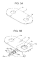
- Fig. 3A is a perspective view of a bus bar shown in Fig. 2 .
- Fig. 3B is a perspective view of the bus bar and a terminal shown in Fig. 2 .
- Fig. 4A is a side view showing an example of automatic wiring machine.
- Fig. 4B is an enlarged perspective view of a pressure-connecting crimper shown in Fig. 4A .
- a battery connector 2 shown in Fig. 2 is attached to a battery assembly 1 shown in Fig. 1 to compose a power unit. Further, this power unit is mounted on an electric vehicle which runs using an electric motor, or a hybrid vehicle which runs using an engine and an electric motor, and supplies electric power to the electric motor.
- the battery assembly 1 includes: a plurality of batteries 10; and a fixing member for overlapping and fixing the batteries with each other.
- each battery 10 includes: a main body of the battery 11 having a box shape; and a positive electrode 12 and a negative electrode 13 respectively projected from one end and the other end of an upper wall of the main body of the battery 11.
- These positive and negative electrodes 12, 13 are respectively formed in a cylinder shape and made of conductive metal.
- a thread groove is provided on an outer peripheral wall of each of positive and negative electrodes 12, 13.
- the positive and negative electrodes 12, 13 are alternately arranged in an overlapping direction in the plurality of batteries 10.
- the number of rows of the positive and negative electrodes 12, 13 alternately arranged is two.
- an arrow X in Fig. 1 indicates an overlapping direction of the plurality of batteries 10 and a longitudinal direction of the battery assembly 1.
- An arrow Z indicates a width direction of the battery assembly 1.
- An arrow Y indicates a height direction of the battery assembly 1.
- the above-described battery connector 2 is mainly for connecting in series the plurality of batteries 10.
- the battery connector 2 includes: a plurality of bus bars 3 for connecting in series the plurality of batteries 10 by connecting the positive electrode with the negative electrode of the batteries 10 adjacent to each other; a plurality of terminals 4 respectively connected to the bus bars 3 for respectively measuring voltages across the terminals of the batteries 10; electric wires 5 respectively connected to the terminals 4; a not-shown earth wire; and a synthetic-resin-made plate 6 receiving them.
- the above-described bus bar 3 is made by pressing a conductive metal plate such as 0.8 mm thick metal plate, and a pair of bus bar holes 3a for inserting the positive and negative electrodes 12, 13 of the batteries 10 adjacent to each other is provided on the plate-shaped metal plate.
- the bus bar 3 is attached to the positive electrode 12 when the positive electrode 12 provided on one of the batteries adjacent to each other is inserted into one of the pair of bus bar holes 3a.
- the bus bar 3 is attached to the negative electrode 13 when the negative electrode 13 provided on the other one of the batteries adjacent to each other is inserted into the other one of the pair of bus bar holes 3a.
- the bus bar 3 is fixed to the batteries 10 when nuts N ( Fig. 1 ) are respectively screwed onto the positive and negative electrodes 12, 13 which are respectively inserted into the bus bar holes 3a.
- the above-described terminal 4 is made by pressing a conductive metal plate.
- a thickness of the metal plate for making the terminal 4 is thinner (for example, 0.4 mm) than the metal plate for making the bus bar 3 because of making a later-described press-connecting blade 42.
- the terminal 4 is composed of a bus bar connecting portion 41 overlapped with the bus bar 3 and electrically connected to the bus bar 3, and a wire connecting portion 42 connected to the bus bar connecting portion 41 and attached to the electric wire 5.
- the bus bar connecting portion 41 is provided with a terminal hole 41a for inserting any one of the positive and negative electrodes 12, 13, and a rotation stop projection 41b projected from an end away from the wire connecting portion 42 for stopping a rotation of terminal 4 on the metal plate.
- An area of the bus bar connecting portion 41 is about half of the area of the bus bar 3.
- the wire connecting portion 42 is provided with a bottom plate 42a on which the electric wire 5 is positioned, a pair of crimping pieces 42b extended vertically from the bottom plate 42a, a pair of side walls 42c extended vertically from the bottom plate 42a and between which the electric wire 5 is positioned, and three pairs of press-connecting blades 42d projected inward from the pair of side walls 42c.
- An insulating cover at an end of the electric wire 5 is crimped with the pair of crimping pieces 42b to fix the electric wire 5 to the wire connecting portion 42.
- the three pairs of press-connecting blades 42d are respectively formed by cutting partially the pair of side walls 42c in substantially C-shape, and pushing inward.
- the three pairs of press-connecting blades 42d are arranged in the longitudinal direction of the electric wire 5 with gaps therebetween.
- the three pairs of press-connecting blades 42d respectively face each other.
- the press-connecting blades 42d cut through the insulating cover of the electric wire 5, and press-connect with the core wire of the electric wire 5.
- the press-connecting blades 42d electrically connect the electric wire 5 with the terminal 4, and prevent the electric wire 5 from being displaced in the longitudinal direction of the wire connecting portion 42.
- the electric wire 5 is attached to the wire connecting portion 42, and the other end of the electric wire 5 is connected to a later-described voltage measuring unit. Further, the electric wire 5 attached to the wire connecting portion 42 (namely, the terminal 4) is arranged in a wire receiving portion 62 of the plate 6.
- the electric wire 5 is a so-called covered wire of which conductive core wire is covered by an insulating cover. Further, the electric wire 5 is a round wire of which cross section is round.
- the plate 6 is formed in a substantially rectangular shape substantially same as a top wall of the battery assembly 1. As shown in Fig. 1 , the plate 6 is overlapped with the top wall of the battery assembly 1. As shown in Figs. 1 and 2 , the plate 6 is provided with a plurality of bus bar receiving portions 61, a plurality of electric wire receiving portions 62, a plurality of electric wire connecting portion receiving portions 63, a plurality of hinges 64.
- the bus bar receiving portion 61 is formed in a box shape into which the bus bar 3 is allowed to be fitted, and receives the bus bar 3 and the bus bar connecting portion 41 overlapped with the bus bar 3.
- the plurality of bus bar receiving portions 61 are arranged along the overlapping direction of the batteries 10, namely, the arrow X direction. Further, as shown in Fig. 1 , two rows of the bus bar receiving portions 61 are arranged with a gap along the width direction of the plate 6, namely, the arrow Z direction. Further, as shown in Fig.
- each bus bar receiving portion 61 is formed in a box shape having a bottom wall 61a of which surface the bus bar 3 is positioned on, and a peripheral wall 61b extended vertically from an outer edge of the bottom wall 61a.
- the bottom wall 61a is provided with a not-shown pair of plate holes for inserting respectively the anode and cathode electrodes 12, 13.
- the peripheral wall 61b is provided with a not-shown slit for inserting the rotation stop projection 41b provided on the bus bar connecting portion 41.
- the rotation stop projection 41b provided on the bus bar connecting portion 41 and the slit provided on the peripheral wall 61b of the bus bar receiving portion 61 make up a rotation stop structure of the terminal 4 upon fastening a nut similar to the conventional way.
- the plurality of electric wire receiving portions 62 is arranged on a straight line parallel to an arranging direction of the bus bar receiving portions 61.
- Each electric wire receiving portion 62 is formed in a gutter shape able to receive the electric wire 5 connected to each terminal 4.
- two rows of the electric wire receiving portions 62 are arranged with a gap along the width direction of the plate 6, namely, the arrow Z direction.
- the two rows of the bus bar receiving portions 61 are interposed between the two rows of the electric wire receiving portions 62.
- each electric wire receiving portion 62 is formed in a gutter shape having a bottom wall 62a of which surface the electric wire 5 is positioned on, and side walls 62b extended vertically from both ends of the bottom wall 62a in the arrow Z direction.
- Each electric wire connecting portion receiving portion 63 connects the bus bar receiving portion 61 and the electric wire receiving portion 62 facing each other with a gap, and receives the wire connecting portion 42 of the terminal 4.
- each electric wire connecting portion receiving portion 63 is formed in a gutter shape having a bottom wall 63a coupling the bottom wall 61a of the bus bar receiving portion 61 with the bottom wall 62a of the electric wire receiving portion 62 facing each other along the width direction of the plate 6, namely, the arrow Z direction, and a pair of coupling walls 63b extended vertically from outer edges of the bottom plate 63a and coupling the peripheral wall 61b of the bus bar receiving portion 61 with the side walls 62b of the electric wire receiving portion 62 facing each other along the width direction of the plate 6.
- the wire connecting portion 42 of the terminal 4 is positioned on a surface of the bottom wall 63a. Further, locking claws 63c for locking on upper walls of a pair of side walls 42c formed on the wire connecting portion 42 are provided on upper walls of the coupling walls 63b.
- the hinge 64 couples the bus bar receiving portions 61 adjacent to each other, and is formed elastically deformable. Further, the hinge 64 is formed in a C-shaped section. A gap between the bus bar receiving portions 61 adjacent to each other is changed by elastically deforming the hinge 64 in a manner that both ends in the C-shape of the hinge 64 is moved close to each other or away from each other, namely, by elastically deforming the hinge 64 in a manner expanding and contracting the both ends in the C-shape of the hinge 64.
- the bus bar 3 is moved close to the bottom wall 61a of the bus bar receiving portion 61 in a manner overlapping with the bottom wall 61a, and the bus bar 3 is fitted into the bus bar receiving portion 61 of the plate 6.
- the bus bar 3 is fitted into the bus bar receiving portion 61, the not-shown plate hole formed on the bus bar receiving portion 61 and the bus bar hole 3a are overlapped with each other.
- each bus bar 3 may be previously insert-molded into the bus bar receiving portion 61.
- the rotation stop projection 41b formed on the bus bar connecting portion 41 of the terminal 4 is inserted into the not-shown slit provided on the peripheral wall 61b of the bus bar receiving portion 61, and the bus bar connecting portion 41 of the terminal is overlapped with the bus bar 3 to receive the terminal 4 in the bus bar receiving portion 61.
- the bus bar connecting portion 41 of the terminal 4 to which the electric wire 5 is already attached is received in the bus bar receiving portion 61.
- the bus bar connecting portion 41 of the terminal 4 to which the electric wire 5 is not attached is received in the bus bar receiving portion 61. Therefore, the terminal 4 may be previously insert-molded into the bus bar receiving portion 61.
- the automatic wiring machine 7 shown in Fig. 4A includes: a wiring head 71; a press-connecting crimper 72; a fixed frame 73 for supporting these members; and an X-Y table 75 for moving back to forth and left to right a wiring board provided on the fixed frame 73.
- a casing 71a of the wiring head 71 is provided movably up and down on an upper plate 76 of the fixed frame 73.
- a wire service tube 77 is provided on an upper end of the upper plate 76.
- a wire supply tube 78 is provided on a bottom end of the casing 71a.
- a pair of press-connecting crimper 72 having an inverted V shape for press-connecting the electric wire 5 is provided movably up and down on a side wall of the casing 71a (see Fig. 4B ).
- the plate 6 receiving the bus bar 3 and the terminal 4 is put on top of the wiring board.
- the X-Y table 75 is moved so that a tip of the wire supply tube 78 is moved along a line on which the electric wire 5 in the electric wire receiving portion 62 is planned to be arranged.
- the X-Y table 75 is moved so that the tip of the wire supply tube 78 is moved from an end of the electric wire receiving portion 62 in the arrow X direction to the wire connecting portion 42 of the terminal 4 which is planned to be connected.
- the electric wire 5 is guided out through the wire supply tube 78 by a not-shown wire feeding machine embedded in the casing 71a in accordance with the movement of the X-Y table 75. Thereby, the electric wire 5 is arranged in the electric wire receiving portion 62.
- the X-Y table 75 is moved so that the electric wire 5 supplied from the wire supply tube 78 is positioned right above the pair of press-connecting blades 42d at the electric wire receiving portion 62 side.
- a side plate 42c of the wire connecting portion 42 is omitted.
- a pair of press-connecting crimpers 72 is moved down, and the electric wire 5 is press-inserted into between the pair of press-connecting blades 42d.
- the press-connecting blades 42d cut through the insulating cover of the electric wire 5, and press-connects the core wire of the electric wire 5.
- the electric wire 5 is press-connected to two remaining pairs of the press-connecting blades 42d with the similar process.
- the movement of the X-Y table 75 is controlled by such as a microcomputer.
- the pair of crimping pieces 42b is crimped to fix the electric wire 5
- the battery connector 2 as the plate 6 to which the bus bar 3, the terminal 4, and the electric wire 5 are attached is attached to the battery assembly 1 similar to the conventional way to finish assembling the power unit.
- the wire connecting portion 42 is composed of at least one pair of press-connecting blades 42d for cutting through the insulating cover of the electric wire 5 and press-connecting the core wire of the electric wire 5 when the electric wire 5 is press-inserted between the press-connecting blades 42d. Therefore, the arrangement of the electric wire 5 can be automated using such as the automatic wiring machine 7 shown in Fig. 4 , and the power unit can reduce costs.
- Fig. 5 is a top view of the battery connector 2 according to the second embodiment of the present invention.
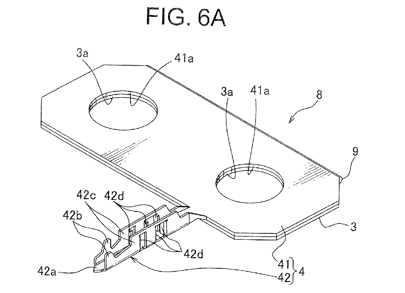
- Fig. 6A is a perspective view showing a bus-bar-terminal unit shown in Fig. 5 .
- Fig. 6B is a perspective view showing the bus-bar-terminal unit shown in Fig. 5 in a condition that the bus-bar-terminal unit is not folded yet.
- the bus bar 3 and the terminal 4 are provided separately.
- the bus bar 3 and the terminal 4 are integrally provided as the bus-bar-terminal unit 8.
- the bus bar 3, the terminal 4, and a coupling portion 9 are formed integrally with each other by pressing one metal plate.
- a pair of bus bar holes 3a for inserting the positive and negative electrodes 12, 13 of the batteries 10 adjacent to each other is provided on the bus bar 3.
- the terminal 4 is composed of the bus bar connecting portion 41 overlapped with the bus bar 3 and electrically connected to the bus bar 3, and the wire connecting portion 42 into which the electric wire 5 connected to the bus bar connecting portion 41 is attached.
- a size and a shape of the bus bar connecting portion 41 are the same as those of the bus bar 3.
- a pair of terminal holes 41a for inserting the positive and negative electrodes 12, 13 is provided on the bus bar connecting portion 41.
- the wire connecting portion 42 is provided with a bottom plate 42a on which the electric wire 5 is positioned, a pair of crimping pieces 42b extended vertically from the bottom plate 42a, a pair of side walls 42c extended vertically from the bottom plate 42a and between which the electric wire 5 is positioned, and three pairs of press-connecting blades 42d projected inward from the pair of side walls 42c.
- the coupling portion 9 couples the bus bar 3 and the terminal 4 together.
- the coupling portion 9 couples an end of the pair of bus bar holes 3a with an end of the pair of terminal holes 41a along the arranging direction (namely, arrow X direction).
- a thickness of the metal plate forming the bus-bar-terminal unit 8 is about half of 1 mm thick (0.4 mm) used in the conventional bus bar 3 for forming the press-connecting blades 42d.
- the metal plate shown in Fig. 6B is folded 180 degree along the coupling portion 9, and the bus bar 3 and the bus bar connecting portion 41 are overlapped with each other.
- a combined thickness of the bus bar 3 and the bus bar connecting portion 41 is substantially the same as the conventional bus bar 3, and the strength thereof is maintained.
- the wire connecting portion 42 is formed by pressing process.
- the plate 6, and the bus-bar-terminal unit 8 are separately produced.
- the bus bar 3 of the bus-bar-terminal unit 8 is moved close to the bottom wall 61a of the bus bar receiving portion 61 in a manner overlapping with the bottom wall 61a, and the bus-bar-terminal unit 8 is fitted into the bus bar receiving portion 61 of the plate 6.
- the bus-bar-terminal unit 8 is fitted into the bus bar receiving portion 61, the not-shown plate hole, the bus bar hole 3a, and the terminal hole 41a are overlapped with each other.
- each bus-bar-terminal unit 8 may be previously insert-molded into the bus bar receiving portion 61.
- the electric wire 5 is not attached to the terminal 4.
- an end of the electric wire 5 is connected to the wire connecting portion 42 of the terminal 4 using, for example, an automatic wiring machine 7 shown in Fig. 4 , and the electric wire 5 is arranged in the electric wire receiving portion 62. Then, after the pair of crimping pieces 42b is crimped to fix the electric wire 5, the battery connector 2 as the plate 6 to which the bus bar 3, the terminal 4, and the electric wire 5 are attached is attached to the battery assembly 1 similar to the conventional way to finish assembling the power unit.
- the wire connecting portion 42 is composed of at least one pair of press-connecting blades 42d for cutting through the insulating cover of the electric wire 5 and press-connecting the core wire of the electric wire 5 when the electric wire 5 is press-inserted between the press-connecting blades 42d. Therefore, the arrangement of the electric wire 5 can be automated using such as the automatic wiring machine 7 shown in Fig. 4 , and the power unit can reduce costs.
- the bus bar connecting portion 41 is integrally formed with the bus bar 3 attached to two electrodes of the positive and negative electrodes 12, 13. Therefore, unlike the first embodiment, the rotation stop structure of the terminal 4 for fastening the nut is unnecessary, and the power unit can reduce costs.
- the bus bar 3 and the terminal 4 can be easily integrated by only coupling the ends of the bus bar 3 and the terminal 4 with the coupling portion 9.
- the bus bar 3 is composed of one of a metal plate folded 180 degree and overlapped
- the terminal 4 is composed of the other of the metal plate folded 180 degree and overlapped. Therefore, the bus bar 3 and the terminal 4 are easily integrated only by folding one metal plate.
- the bus bar 3 is composed of one of a metal plate folded 180 degree and overlapped
- the terminal 4 is composed of the other of the metal plate folded 180 degree and overlapped.
- the present invention is not limited to this.
- the wire connecting portion 42 is provided at an end of one metal plate, and this metal plate may be used as both the bus bar 3 and the bus bar connecting portion 41.
- the wire connecting portion 42 is integrally provided with the bus bar connecting portion 41.
- the present invention is not limited to this.
- the bus bar connecting portion 41 and the wire connecting portion 42 may be separated from each other.
- the coupling portion 9 is provided along the arranging direction of the bus bar 3, the pair of bus bar holes 3a of the bus bar connecting portion 41, and the terminal holes 41a (namely, arrow X direction).
- the present invention is not limited to this.
- the coupling portion 9 may be provided along a direction perpendicular to the arranging direction of the bus bar 3 and the bus bar connecting portion 41 (namely, arrow Z direction).
Landscapes
- Chemical & Material Sciences (AREA)
- Chemical Kinetics & Catalysis (AREA)
- Electrochemistry (AREA)
- General Chemical & Material Sciences (AREA)
- Engineering & Computer Science (AREA)
- Manufacturing & Machinery (AREA)
- Connection Of Batteries Or Terminals (AREA)
- Battery Mounting, Suspending (AREA)
Abstract
Description
- This invention relates to a power unit and a battery connector, in particular, to the power unit mounted on a hybrid vehicle or an electric vehicle, and to the battery connector used in the above power unit.
- For example, the above-described power unit as a driving source for an electric motor is mounted on an electric vehicle running by the electric motor or the like, a hybrid vehicle running with a combination of an engine and the electric motor, or the like. The power unit is composed of a battery assembly 1 (
Fig. 1 ) and a battery connector 2 (Fig. 7 ) attached to thebattery assembly 1. As shown inFig. 1 , thebattery assembly 1 is composed of a plurality ofbatteries 10 arranged side-by-side relationship. Apositive electrode 12 and anegative electrode 13 projected from a box-shaped chassis are provided with eachbattery 10. Thepositive electrodes 12 and thenegative electrodes 13 are overlapped with each other in a manner that they are alternately arranged in the plurality ofbatteries 10. - As shown in
Fig. 7 , thebattery connector 2 includes: a plurality ofbus bars 3 for directly connecting the plurality ofbatteries 10 by connecting thepositive electrode 12 and thenegative electrode 13 of thebatteries 10 adjacent to each other; aterminal 4 connected to eachbus bar 3; anelectric wire 5 connected to theterminal 4; a not-shown earth wire; and a synthetic-resin-madeplate 6 receiving them. - A pair of
bus bar holes 3a for respectively inserting thepositive electrode 12 and thenegative electrode 13 of thebatteries 10 adjacent to each other is provided with thebus bar 3. When thepositive electrode 12 mounted on one of thebatteries 10 adjacent to each other is inserted into one of the pair ofbus bar holes 3a, thebus bar 3 is attached to thepositive electrode 12. When thenegative electrode 13 mounted on the other one of thebatteries 10 adjacent to each other is inserted into the other one of the pair ofbus bar holes 3a, thebus bar 3 is attached to thenegative electrode 13. By attaching in this manner, thebus bar 3 electrically connects thepositive electrode 12 and thenegative electrode 13 of thebatteries 10 adjacent to each other. - The
terminal 4 is composed of a busbar connecting portion 41 and an electricwire connecting portion 42. Aterminal hole 41a for inserting any one of thepositive electrode 12 and the negative electrode is provided with the busbar connecting portion 41. The busbar connecting portion 41 is overlapped with thebus bar 3 while any one of thepositive electrode 12 and thenegative electrode 13 is inserted into theterminal hole 41a. An area of the busbar connecting portion 41 is about half of the area of thebus bar 3. The electricwire connecting portion 42 is integrally provided with the busbar connecting portion 41. The electricwire connecting portion 42 is composed of a pair of crimpingpieces 100 with which a core wire of theelectric wire 5 is crimped. Theelectric wire 5 is connected to a not-shown voltage measuring unit for measuring a voltage across each of thebatteries 10. - A bus
bar receiving portion 61, an electricwire receiving portion 62, an electric wire connectingportion receiving portion 63, and the like are integrally provided with theplate 6. The busbar receiving portion 61 is formed in a box shape allowed to fit thebus bar 3 thereinto, and receives thebus bar 3 and the busbar connecting portion 41 overlapped with thebus bar 3. A pair of not-shown plate holes for respectively inserting thepositive electrode 12 and thenegative electrode 13 is provided on a bottom wall of the busbar receiving portion 61. The electricwire receiving portion 62 is formed in a gutter shape, and receives theelectric wire 5. The electric wire connectingportion receiving portion 63 is formed in a gutter shape for communicating the busbar receiving portion 61 with the electricwire receiving portion 62, and receives the electricwire connecting portion 42. - The power unit having the above-described structure is assembled as follows. When assembling the power unit, the
bus bar 3, theterminal 4, theplate 6, and the like have been separately produced. Further, theelectric wire 5 is previously connected to theterminal 4. Incidentally, a connection procedure of theterminal 4 and theelectric wire 5 is done as follows. First, the core wire of theelectric wire 5 is exposed by removing an insulating cover at an end of theelectric wire 5. Then, the core wire is positioned between the pair of crimpingpieces 100, and the pair of crimping pieces is crimped to pressure-bond theelectric wire 5 to the electricwire connecting portion 42. - Next, the
bus bar 3 is received in the busbar receiving portion 61 of theplate 6 in a manner that the not-shown plate hole is overlapped with thebus bar hole 3a. Next, the busbar connecting portion 41 is overlapped with thebus bar 3 and received in the busbar receiving portion 61 in a manner that theterminal hole 41a is overlapped with one of the pair ofbus bar holes 3a. At this time, the busbar connecting portion 41 is overlapped with thebus bar 3 in a manner that the electricwire connecting portion 42 is received in the electric wire connectingportion receiving portion 63. Then, theelectric wire 5 is arranged in the electricwire receiving portion 62. - Next, the
battery connector 2 assembled according to the above described procedure is attached to thebattery assembly 1. Namely, onepositive electrode 12 of thebatteries 10 adjacent to each other is inserted into one of the pair of not-shown plate holes and one of the pair ofbus bar holes 3a overlapped with each other, and onenegative electrode 13 of thebatteries 10 is inserted into the other one of the pair of not-shown plate holes and the other one of thebus bar holes 3a. Further, thebattery connector 2 is arranged on an upper wall of thebattery assembly 1 in a manner that any one of thepositive electrode 12 and thenegative electrode 13 is inserted into theterminal hole 41a. Then, by respectively screwing nuts onto thenegative electrode 13 and thepositive electrode 12 of thebatteries 10, thebattery connector 2 is fixed to thebatteries 10. -
- Patent Document 1:
JP, A, 2006-269104 - According to the above-described power unit, because the electric
wire connecting portion 42 is composed of a pair ofcrimping pieces 100 for crimping theelectric wire 5, it is necessary to arrange theelectric wire 5 in the electricwire receiving portion 62 by hand work, and there is a problem about cost. Further, theterminal 4 is passed through only any one of thepositive electrode 12 or thenegative electrode 13. Therefore, when the nut is tightened, theterminal 4 may be rotated about thepositive electrode 12 or thenegative electrode 13 though which theterminal hole 41a is passed, and a load may be generated in the electricwire connecting portion 42. For preventing this, the conventional power unit is provided with a rotation stop structure of theterminal 4 composed of arotation stop projection 41b formed on thebus bar 3 of theterminal 4, and a slit formed on a side wall of the busbar receiving portion 61 for inserting therotation stop projection 41b. Thereby, when theterminal 4 is tried to rotate upon tightening the nut, therotation stop projection 41b abuts on an inner wall of the slit to prevent the rotation. According to the conventional power unit, it is necessary to provide the rotation stop structure described above with thebattery connector 2, thereby a structure of the power unit becomes complex, and there is a problem about cost. - Accordingly, an object of the present invention is to provide a power unit and a battery connector configured to reduce costs by automatizing an arrangement of the electric wire.
- For attaining the object, according to the invention described in
claim 1, there is provided a power unit comprising: - a battery assembly having a plurality of batteries arranged side-by-side relationship so as to have positive and negative electrodes alternate in each of the batteries;
- a bus bar for connecting in series the plurality of batteries by connecting the positive electrode with the negative electrode in each of the adjacent batteries;
- a terminal connected to the bus bar, having an electric wire; and at least a pair of press-connecting blades provided in the terminal for cutting through an insulating cover of the electric wire and press-contacting a core wire of the electric wire so as to permit the electric wire to be press-fitted into between the press-connecting blades.
- According to the invention described in
claim 2, there is provided the power unit as claimed inclaim 1,
wherein the bus bar and the terminal are formed integrally with each other. - According to the invention described in
claim 3, there is provided the power unit as claimed inclaim 2,
wherein the terminal includes a coupling portion overlapped with the bus bar for coupling and integrating an end of the bus bar and an end of the terminal with each other. - According to the invention described in
claim 4, there is provided the power unit as claimed inclaim 3,
wherein the bus bar and the terminal are made of a sheet of a metal plate folded 180 degree and overlapped. - According to the invention described in
claim 5, there is provided a battery connector comprising: - a bus bar for connecting in series a plurality of batteries arranged side-by-side relationship so as to have positive and negative electrodes alternate in each of the batteries by connecting the positive electrode with the negative electrode in each of the adjacent batteries;
- a terminal connected to the bus bar having an electric wire; and at least a pair of press-connecting blades provided in the terminal for cutting through an insulating cover of the electric wire and press-contacting a core wire of the electric wire so as to permit the electric wire to be press-fitted into between the press-connecting blades.
- As explained the above, according to the inventions claimed in
claims - According to the invention as claimed in
claim 2, because the terminal is integrally formed with the bus bar attached to the two electrodes of the positive electrode and the negative electrode, there is no need to provide a rotation stop structure of the terminal when a nut is tightened to the electrode, and thereby, the power unit can reduce costs. - According to the invention as claimed in
claim 3, the bus bar and the terminal can be easily integrated with each other by coupling the end of the bus bar and the end of the terminal with the coupling portion. - According to the invention as claimed in
claim 4, the bus bar and the terminal can be easily integrated with each other by folding a metal plate. Brief description of drawings - [
Fig. 1 ] An exploded perspective view showing an embodiment of a power unit according to the present invention. - [
Fig. 2 ] A partially top view of a battery connector shown inFig. 1 according to the first embodiment. - [
Fig. 3A ] A perspective view of a bus bar shown inFig. 2 . - [
Fig. 3B ] A perspective view of the bus bar and a terminal shown inFig. 2 . - [
Fig. 4A ] A side view showing an example of automatic wiring machine. - [
Fig. 4B ] A partially perspective view of the automatic wiring machine shown inFig. 4 (A) . - [
Fig. 5 ] A top view of the battery connector according to a second embodiment of the present invention. - [
Fig. 6A ] A perspective view showing a bus-bar-terminal unit shown inFig. 5 . - [
Fig. 6B ] A perspective view showing the bus-bar-terminal unit shown inFig. 5 in a condition that the bus-bar-terminal unit is not folded yet. - [
Fig. 7 ] A top view showing an example of a conventional battery connector. - Hereinafter, a first embodiment of the present invention will be explained with reference to
Figs. 1 to 4 .Fig. 1 is an exploded perspective view showing an embodiment of a power unit according to the present invention.Fig. 2 is a partially top view of a battery connector shown inFig. 1 according to the first embodiment.Fig. 3A is a perspective view of a bus bar shown inFig. 2 .Fig. 3B is a perspective view of the bus bar and a terminal shown inFig. 2 .Fig. 4A is a side view showing an example of automatic wiring machine.Fig. 4B is an enlarged perspective view of a pressure-connecting crimper shown inFig. 4A . - A
battery connector 2 shown inFig. 2 is attached to abattery assembly 1 shown inFig. 1 to compose a power unit. Further, this power unit is mounted on an electric vehicle which runs using an electric motor, or a hybrid vehicle which runs using an engine and an electric motor, and supplies electric power to the electric motor. - As shown in
Fig. 1 , thebattery assembly 1 includes: a plurality ofbatteries 10; and a fixing member for overlapping and fixing the batteries with each other. Further, eachbattery 10 includes: a main body of thebattery 11 having a box shape; and apositive electrode 12 and anegative electrode 13 respectively projected from one end and the other end of an upper wall of the main body of thebattery 11. These positive andnegative electrodes negative electrodes - Further, the positive and
negative electrodes batteries 10. The number of rows of the positive andnegative electrodes Fig. 1 indicates an overlapping direction of the plurality ofbatteries 10 and a longitudinal direction of thebattery assembly 1. An arrow Z indicates a width direction of thebattery assembly 1. An arrow Y indicates a height direction of thebattery assembly 1. - The above-described
battery connector 2 is mainly for connecting in series the plurality ofbatteries 10. As shown inFig. 2 , thebattery connector 2 includes: a plurality ofbus bars 3 for connecting in series the plurality ofbatteries 10 by connecting the positive electrode with the negative electrode of thebatteries 10 adjacent to each other; a plurality ofterminals 4 respectively connected to thebus bars 3 for respectively measuring voltages across the terminals of thebatteries 10;electric wires 5 respectively connected to theterminals 4; a not-shown earth wire; and a synthetic-resin-madeplate 6 receiving them. - As shown in
Fig. 3A , the above-describedbus bar 3 is made by pressing a conductive metal plate such as 0.8 mm thick metal plate, and a pair ofbus bar holes 3a for inserting the positive andnegative electrodes batteries 10 adjacent to each other is provided on the plate-shaped metal plate. Thebus bar 3 is attached to thepositive electrode 12 when thepositive electrode 12 provided on one of the batteries adjacent to each other is inserted into one of the pair ofbus bar holes 3a. Further, thebus bar 3 is attached to thenegative electrode 13 when thenegative electrode 13 provided on the other one of the batteries adjacent to each other is inserted into the other one of the pair ofbus bar holes 3a. Then, thebus bar 3 is fixed to thebatteries 10 when nuts N (Fig. 1 ) are respectively screwed onto the positive andnegative electrodes bus bar holes 3a. - The above-described
terminal 4 is made by pressing a conductive metal plate. A thickness of the metal plate for making theterminal 4 is thinner (for example, 0.4 mm) than the metal plate for making thebus bar 3 because of making a later-described press-connectingblade 42. As shown inFig. 3B , theterminal 4 is composed of a busbar connecting portion 41 overlapped with thebus bar 3 and electrically connected to thebus bar 3, and awire connecting portion 42 connected to the busbar connecting portion 41 and attached to theelectric wire 5. The busbar connecting portion 41 is provided with aterminal hole 41a for inserting any one of the positive andnegative electrodes rotation stop projection 41b projected from an end away from thewire connecting portion 42 for stopping a rotation ofterminal 4 on the metal plate. An area of the busbar connecting portion 41 is about half of the area of thebus bar 3. Thewire connecting portion 42 is provided with abottom plate 42a on which theelectric wire 5 is positioned, a pair of crimpingpieces 42b extended vertically from thebottom plate 42a, a pair ofside walls 42c extended vertically from thebottom plate 42a and between which theelectric wire 5 is positioned, and three pairs of press-connectingblades 42d projected inward from the pair ofside walls 42c. - An insulating cover at an end of the
electric wire 5 is crimped with the pair of crimpingpieces 42b to fix theelectric wire 5 to thewire connecting portion 42. The three pairs of press-connectingblades 42d are respectively formed by cutting partially the pair ofside walls 42c in substantially C-shape, and pushing inward. The three pairs of press-connectingblades 42d are arranged in the longitudinal direction of theelectric wire 5 with gaps therebetween. The three pairs of press-connectingblades 42d respectively face each other. When theelectric wire 5 is press-inserted therebetween, the press-connectingblades 42d cut through the insulating cover of theelectric wire 5, and press-connect with the core wire of theelectric wire 5. Thus, the press-connectingblades 42d electrically connect theelectric wire 5 with theterminal 4, and prevent theelectric wire 5 from being displaced in the longitudinal direction of thewire connecting portion 42. - One end of the
electric wire 5 is attached to thewire connecting portion 42, and the other end of theelectric wire 5 is connected to a later-described voltage measuring unit. Further, theelectric wire 5 attached to the wire connecting portion 42 (namely, the terminal 4) is arranged in awire receiving portion 62 of theplate 6. Theelectric wire 5 is a so-called covered wire of which conductive core wire is covered by an insulating cover. Further, theelectric wire 5 is a round wire of which cross section is round. - The
plate 6 is formed in a substantially rectangular shape substantially same as a top wall of thebattery assembly 1. As shown inFig. 1 , theplate 6 is overlapped with the top wall of thebattery assembly 1. As shown inFigs. 1 and2 , theplate 6 is provided with a plurality of busbar receiving portions 61, a plurality of electricwire receiving portions 62, a plurality of electric wire connectingportion receiving portions 63, a plurality of hinges 64. - As shown in
Figs. 1 and2 , the busbar receiving portion 61 is formed in a box shape into which thebus bar 3 is allowed to be fitted, and receives thebus bar 3 and the busbar connecting portion 41 overlapped with thebus bar 3. The plurality of busbar receiving portions 61 are arranged along the overlapping direction of thebatteries 10, namely, the arrow X direction. Further, as shown inFig. 1 , two rows of the busbar receiving portions 61 are arranged with a gap along the width direction of theplate 6, namely, the arrow Z direction. Further, as shown inFig. 2 , each busbar receiving portion 61 is formed in a box shape having abottom wall 61a of which surface thebus bar 3 is positioned on, and aperipheral wall 61b extended vertically from an outer edge of thebottom wall 61a. Further, thebottom wall 61a is provided with a not-shown pair of plate holes for inserting respectively the anode andcathode electrodes peripheral wall 61b is provided with a not-shown slit for inserting therotation stop projection 41b provided on the busbar connecting portion 41. Therotation stop projection 41b provided on the busbar connecting portion 41 and the slit provided on theperipheral wall 61b of the busbar receiving portion 61 make up a rotation stop structure of theterminal 4 upon fastening a nut similar to the conventional way. - The plurality of electric
wire receiving portions 62 is arranged on a straight line parallel to an arranging direction of the busbar receiving portions 61. Each electricwire receiving portion 62 is formed in a gutter shape able to receive theelectric wire 5 connected to eachterminal 4. Further, as shown inFig. 1 , two rows of the electricwire receiving portions 62 are arranged with a gap along the width direction of theplate 6, namely, the arrow Z direction. Further, the two rows of the busbar receiving portions 61 are interposed between the two rows of the electricwire receiving portions 62. Further, as shown inFig. 2 , each electricwire receiving portion 62 is formed in a gutter shape having abottom wall 62a of which surface theelectric wire 5 is positioned on, andside walls 62b extended vertically from both ends of thebottom wall 62a in the arrow Z direction. - Each electric wire connecting
portion receiving portion 63 connects the busbar receiving portion 61 and the electricwire receiving portion 62 facing each other with a gap, and receives thewire connecting portion 42 of theterminal 4. As shown inFig. 1 , each electric wire connectingportion receiving portion 63 is formed in a gutter shape having a bottom wall 63a coupling thebottom wall 61a of the busbar receiving portion 61 with thebottom wall 62a of the electricwire receiving portion 62 facing each other along the width direction of theplate 6, namely, the arrow Z direction, and a pair of coupling walls 63b extended vertically from outer edges of the bottom plate 63a and coupling theperipheral wall 61b of the busbar receiving portion 61 with theside walls 62b of the electricwire receiving portion 62 facing each other along the width direction of theplate 6. Thewire connecting portion 42 of theterminal 4 is positioned on a surface of the bottom wall 63a. Further, lockingclaws 63c for locking on upper walls of a pair ofside walls 42c formed on thewire connecting portion 42 are provided on upper walls of the coupling walls 63b. - The
hinge 64 couples the busbar receiving portions 61 adjacent to each other, and is formed elastically deformable. Further, thehinge 64 is formed in a C-shaped section. A gap between the busbar receiving portions 61 adjacent to each other is changed by elastically deforming thehinge 64 in a manner that both ends in the C-shape of thehinge 64 is moved close to each other or away from each other, namely, by elastically deforming thehinge 64 in a manner expanding and contracting the both ends in the C-shape of thehinge 64. - Next, an assembling procedure of the above-described power unit will be explained. Before assembling the power unit, the
plate 6, thebus bar 3, theterminal 4, and the like are separately produced. First, thebus bar 3 is moved close to thebottom wall 61a of the busbar receiving portion 61 in a manner overlapping with thebottom wall 61a, and thebus bar 3 is fitted into the busbar receiving portion 61 of theplate 6. When thebus bar 3 is fitted into the busbar receiving portion 61, the not-shown plate hole formed on the busbar receiving portion 61 and thebus bar hole 3a are overlapped with each other. Alternately, eachbus bar 3 may be previously insert-molded into the busbar receiving portion 61. Next, therotation stop projection 41b formed on the busbar connecting portion 41 of theterminal 4 is inserted into the not-shown slit provided on theperipheral wall 61b of the busbar receiving portion 61, and the busbar connecting portion 41 of the terminal is overlapped with thebus bar 3 to receive theterminal 4 in the busbar receiving portion 61. Conventionally, the busbar connecting portion 41 of theterminal 4 to which theelectric wire 5 is already attached is received in the busbar receiving portion 61. However, according to the present invention, the busbar connecting portion 41 of theterminal 4 to which theelectric wire 5 is not attached is received in the busbar receiving portion 61. Therefore, theterminal 4 may be previously insert-molded into the busbar receiving portion 61. - Next, an end of the
electric wire 5 is connected to thewire connecting portion 42 of theterminal 4 using, for example, an automatic wiring machine 7 shown inFig. 4 , and theelectric wire 5 is arranged in the electricwire receiving portion 62. Hereinafter, the automatic wiring machine 7 shown inFig. 4A will be explained. As shown inFig. 4A , the automatic wiring machine 7 includes: a wiringhead 71; a press-connectingcrimper 72; a fixedframe 73 for supporting these members; and an X-Y table 75 for moving back to forth and left to right a wiring board provided on the fixedframe 73. - A
casing 71a of thewiring head 71 is provided movably up and down on anupper plate 76 of the fixedframe 73. Awire service tube 77 is provided on an upper end of theupper plate 76. Further, awire supply tube 78 is provided on a bottom end of thecasing 71a. Further, a pair of press-connectingcrimper 72 having an inverted V shape for press-connecting theelectric wire 5 is provided movably up and down on a side wall of thecasing 71a (seeFig. 4B ). Next, a process to connect an end of theelectric wire 5 with thewire connecting portion 42 and a process to arrange theelectric wire 5 in the electricwire receiving portion 62 using the automatic wiring machine 7 shown inFig. 4 will be explained. - The
plate 6 receiving thebus bar 3 and theterminal 4 is put on top of the wiring board. Next, the X-Y table 75 is moved so that a tip of thewire supply tube 78 is moved along a line on which theelectric wire 5 in the electricwire receiving portion 62 is planned to be arranged. In detail, the X-Y table 75 is moved so that the tip of thewire supply tube 78 is moved from an end of the electricwire receiving portion 62 in the arrow X direction to thewire connecting portion 42 of theterminal 4 which is planned to be connected. Theelectric wire 5 is guided out through thewire supply tube 78 by a not-shown wire feeding machine embedded in thecasing 71a in accordance with the movement of the X-Y table 75. Thereby, theelectric wire 5 is arranged in the electricwire receiving portion 62. - After the
wire supply tube 78 is moved to thewire connecting portion 42 of theterminal 4, as shown inFig. 4B , the X-Y table 75 is moved so that theelectric wire 5 supplied from thewire supply tube 78 is positioned right above the pair of press-connectingblades 42d at the electricwire receiving portion 62 side. Incidentally, inFig. 4B , aside plate 42c of thewire connecting portion 42 is omitted. Then, a pair of press-connectingcrimpers 72 is moved down, and theelectric wire 5 is press-inserted into between the pair of press-connectingblades 42d. Thereby, the press-connectingblades 42d cut through the insulating cover of theelectric wire 5, and press-connects the core wire of theelectric wire 5. Then, theelectric wire 5 is press-connected to two remaining pairs of the press-connectingblades 42d with the similar process. The movement of the X-Y table 75 is controlled by such as a microcomputer. Then, after the pair of crimpingpieces 42b is crimped to fix theelectric wire 5, thebattery connector 2 as theplate 6 to which thebus bar 3, theterminal 4, and theelectric wire 5 are attached is attached to thebattery assembly 1 similar to the conventional way to finish assembling the power unit. - According to the above-described power unit, the
wire connecting portion 42 is composed of at least one pair of press-connectingblades 42d for cutting through the insulating cover of theelectric wire 5 and press-connecting the core wire of theelectric wire 5 when theelectric wire 5 is press-inserted between the press-connectingblades 42d. Therefore, the arrangement of theelectric wire 5 can be automated using such as the automatic wiring machine 7 shown inFig. 4 , and the power unit can reduce costs. - Next, a second embodiment of the present invention will be explained with reference to
Figs. 5 ,6A , and6B .Fig. 5 is a top view of thebattery connector 2 according to the second embodiment of the present invention.Fig. 6A is a perspective view showing a bus-bar-terminal unit shown inFig. 5 .Fig. 6B is a perspective view showing the bus-bar-terminal unit shown inFig. 5 in a condition that the bus-bar-terminal unit is not folded yet. - In the first embodiment described above, the
bus bar 3 and theterminal 4 are provided separately. In the second embodiment, thebus bar 3 and theterminal 4 are integrally provided as the bus-bar-terminal unit 8. As shown inFig. 6A , in the bus-bar-terminal unit 8, thebus bar 3, theterminal 4, and acoupling portion 9 are formed integrally with each other by pressing one metal plate. Similar to the first embodiment, a pair ofbus bar holes 3a for inserting the positive andnegative electrodes batteries 10 adjacent to each other is provided on thebus bar 3. Similar to the first embodiment, theterminal 4 is composed of the busbar connecting portion 41 overlapped with thebus bar 3 and electrically connected to thebus bar 3, and thewire connecting portion 42 into which theelectric wire 5 connected to the busbar connecting portion 41 is attached. - Unlike the first embodiment, a size and a shape of the bus
bar connecting portion 41 are the same as those of thebus bar 3. A pair ofterminal holes 41a for inserting the positive andnegative electrodes bar connecting portion 41. Similar to the first embodiment, thewire connecting portion 42 is provided with abottom plate 42a on which theelectric wire 5 is positioned, a pair of crimpingpieces 42b extended vertically from thebottom plate 42a, a pair ofside walls 42c extended vertically from thebottom plate 42a and between which theelectric wire 5 is positioned, and three pairs of press-connectingblades 42d projected inward from the pair ofside walls 42c. Because thebottom plate 42a, the pair of crimpingpieces 42b, the pair ofside walls 42c, and the press-connectingblades 42d are already explained in the first embodiment, a detailed explanation of those is omitted here. Thecoupling portion 9 couples thebus bar 3 and theterminal 4 together. Thecoupling portion 9 couples an end of the pair ofbus bar holes 3a with an end of the pair ofterminal holes 41a along the arranging direction (namely, arrow X direction). - Next, a production process of the bus-bar-
terminal unit 8 will be explained. First, a sheet of metal is punched as shown inFig. 6B . A thickness of the metal plate forming the bus-bar-terminal unit 8 is about half of 1 mm thick (0.4 mm) used in theconventional bus bar 3 for forming the press-connectingblades 42d. The metal plate shown inFig. 6B is folded 180 degree along thecoupling portion 9, and thebus bar 3 and the busbar connecting portion 41 are overlapped with each other. A combined thickness of thebus bar 3 and the busbar connecting portion 41 is substantially the same as theconventional bus bar 3, and the strength thereof is maintained. Then, thewire connecting portion 42 is formed by pressing process. - Next, an assembling procedure of the above-described power unit will be explained. Before assembling the power unit, the
plate 6, and the bus-bar-terminal unit 8 are separately produced. First, thebus bar 3 of the bus-bar-terminal unit 8 is moved close to thebottom wall 61a of the busbar receiving portion 61 in a manner overlapping with thebottom wall 61a, and the bus-bar-terminal unit 8 is fitted into the busbar receiving portion 61 of theplate 6. When the bus-bar-terminal unit 8 is fitted into the busbar receiving portion 61, the not-shown plate hole, thebus bar hole 3a, and theterminal hole 41a are overlapped with each other. Alternately, each bus-bar-terminal unit 8 may be previously insert-molded into the busbar receiving portion 61. Incidentally, when the bus-bar-terminal unit 8 is fitted into the busbar receiving portion 61, similar to the first embodiment, theelectric wire 5 is not attached to theterminal 4. - Next, similar to the first embodiment, an end of the
electric wire 5 is connected to thewire connecting portion 42 of theterminal 4 using, for example, an automatic wiring machine 7 shown inFig. 4 , and theelectric wire 5 is arranged in the electricwire receiving portion 62. Then, after the pair of crimpingpieces 42b is crimped to fix theelectric wire 5, thebattery connector 2 as theplate 6 to which thebus bar 3, theterminal 4, and theelectric wire 5 are attached is attached to thebattery assembly 1 similar to the conventional way to finish assembling the power unit. - According to the above-described power unit, similar to the first embodiment, the
wire connecting portion 42 is composed of at least one pair of press-connectingblades 42d for cutting through the insulating cover of theelectric wire 5 and press-connecting the core wire of theelectric wire 5 when theelectric wire 5 is press-inserted between the press-connectingblades 42d. Therefore, the arrangement of theelectric wire 5 can be automated using such as the automatic wiring machine 7 shown inFig. 4 , and the power unit can reduce costs. - Further, according to the above-described power unit, the bus
bar connecting portion 41 is integrally formed with thebus bar 3 attached to two electrodes of the positive andnegative electrodes terminal 4 for fastening the nut is unnecessary, and the power unit can reduce costs. - Further, according to the above-described power unit, the
bus bar 3 and theterminal 4 can be easily integrated by only coupling the ends of thebus bar 3 and theterminal 4 with thecoupling portion 9. - Further, according to the above-described power unit, the
bus bar 3 is composed of one of a metal plate folded 180 degree and overlapped, and theterminal 4 is composed of the other of the metal plate folded 180 degree and overlapped. Therefore, thebus bar 3 and theterminal 4 are easily integrated only by folding one metal plate. - Incidentally, according to the above-described embodiment, the
bus bar 3 is composed of one of a metal plate folded 180 degree and overlapped, and theterminal 4 is composed of the other of the metal plate folded 180 degree and overlapped. However, the present invention is not limited to this. For example, thewire connecting portion 42 is provided at an end of one metal plate, and this metal plate may be used as both thebus bar 3 and the busbar connecting portion 41. - Further, according to the first and second embodiments, the
wire connecting portion 42 is integrally provided with the busbar connecting portion 41. However, the present invention is not limited to this. For example, the busbar connecting portion 41 and thewire connecting portion 42 may be separated from each other. - Further, according to the second embodiment, the
coupling portion 9 is provided along the arranging direction of thebus bar 3, the pair ofbus bar holes 3a of the busbar connecting portion 41, and theterminal holes 41a (namely, arrow X direction). However, the present invention is not limited to this. For example, thecoupling portion 9 may be provided along a direction perpendicular to the arranging direction of thebus bar 3 and the bus bar connecting portion 41 (namely, arrow Z direction). - Although the present invention has been fully described by way of example with reference to the accompanying drawings, it is to be understood that various changes and modifications will be apparent to those skilled in the art. Therefore, unless otherwise such changes and modifications depart from the scope of the present invention hereinafter defined, they should be construed as being included therein.
-
- 1
- battery assembly
- 3
- bus bar
- 4
- terminal
- 5
- electric wire
- 9
- coupling portion
- 10
- battery
- 12
- positive electrode
- 13
- negative electrode
- 42d
- press-connecting blade
Claims (5)
- A power unit comprising:a battery assembly having a plurality of batteries arranged side-by-side relationship so as to have positive and negative electrodes alternate in each of the batteries;a bus bar for connecting in series the plurality of batteries by connecting the positive electrode with the negative electrode in each of the adjacent batteries;a terminal connected to the bus bar, having an electric wire; andat least a pair of press-connecting blades provided in the terminal for cutting through an insulating cover of the electric wire and press-contacting a core wire of the electric wire so as to permit the electric wire to be press-fitted into between the press-connecting blades.
- The power unit as claimed in claim 1,
wherein the bus bar and the terminal are formed integrally with each other. - The power unit as claimed in claim 2,
wherein the terminal includes a coupling portion overlapped with the bus bar for coupling and integrating an end of the bus bar and an end of the terminal with each other. - The power unit as claimed in claim 3,
wherein the bus bar and the terminal are made of a sheet of a metal plate folded 180 degree and overlapped. - A battery connector comprising:a bus bar for connecting in series a plurality of batteries arranged side-by-side relationship so as to have positive and negative electrodes alternate in each of the batteries by connecting the positive electrode with the negative electrode in each of the adjacent batteries;a terminal connected to the bus bar having an electric wire; andat least a pair of press-connecting blades provided in the terminal for cutting through an insulating cover of the electric wire and press-contacting a core wire of the electric wire so as to permit the electric wire to be press-fitted into between the press-connecting blades.
Applications Claiming Priority (2)
| Application Number | Priority Date | Filing Date | Title |
|---|---|---|---|
| JP2009188893 | 2009-08-18 | ||
| PCT/JP2010/063842 WO2011021614A1 (en) | 2009-08-18 | 2010-08-17 | Power-supply device and battery connector |
Publications (3)
| Publication Number | Publication Date |
|---|---|
| EP2469626A1 true EP2469626A1 (en) | 2012-06-27 |
| EP2469626A4 EP2469626A4 (en) | 2015-10-14 |
| EP2469626B1 EP2469626B1 (en) | 2018-01-10 |
Family
ID=43607065
Family Applications (1)
| Application Number | Title | Priority Date | Filing Date |
|---|---|---|---|
| EP10809955.7A Active EP2469626B1 (en) | 2009-08-18 | 2010-08-17 | Power-supply device and battery connector |
Country Status (5)
| Country | Link |
|---|---|
| US (1) | US8388382B2 (en) |
| EP (1) | EP2469626B1 (en) |
| JP (1) | JP5443495B2 (en) |
| CN (1) | CN102414871B (en) |
| WO (1) | WO2011021614A1 (en) |
Families Citing this family (63)
| Publication number | Priority date | Publication date | Assignee | Title |
|---|---|---|---|---|
| US8460818B2 (en) * | 2009-10-05 | 2013-06-11 | Samsung Sdi Co., Ltd. | Battery module |
| JP5632193B2 (en) | 2010-05-11 | 2014-11-26 | 矢崎総業株式会社 | Battery connecting member and battery connecting body |
| US8785781B2 (en) | 2010-06-21 | 2014-07-22 | Samsung Sdi Co., Ltd. | Connecting tab of battery pack, coupling structure between the connecting tab and wire, and coupling method thereof |
| JP5345175B2 (en) * | 2010-06-21 | 2013-11-20 | 三星エスディアイ株式会社 | Battery pack connector and method of connecting the same |
| JP5780788B2 (en) * | 2011-03-18 | 2015-09-16 | 矢崎総業株式会社 | Bus bar, bus bar module, power supply |
| JP5668555B2 (en) * | 2011-03-18 | 2015-02-12 | 株式会社オートネットワーク技術研究所 | Battery module |
| KR101276186B1 (en) * | 2011-05-13 | 2013-06-18 | 주식회사 엘지화학 | Voltage Sensing Assembly and Battery Module Employed with the Same |
| JP5809465B2 (en) * | 2011-07-05 | 2015-11-11 | 矢崎総業株式会社 | Electric wire routing device |
| JP5939421B2 (en) * | 2011-07-07 | 2016-06-22 | 株式会社オートネットワーク技術研究所 | Battery wiring module |
| JP5673464B2 (en) * | 2011-09-15 | 2015-02-18 | 株式会社オートネットワーク技術研究所 | Battery wiring module |
| JP5673465B2 (en) * | 2011-09-15 | 2015-02-18 | 株式会社オートネットワーク技術研究所 | Battery wiring module |
| JP5834769B2 (en) | 2011-10-26 | 2015-12-24 | 株式会社オートネットワーク技術研究所 | Battery wiring module |
| JP5741948B2 (en) * | 2011-11-11 | 2015-07-01 | 株式会社オートネットワーク技術研究所 | Battery wiring module |
| JP5875107B2 (en) * | 2011-12-07 | 2016-03-02 | 矢崎総業株式会社 | Battery connector |
| JP5817535B2 (en) * | 2012-01-06 | 2015-11-18 | 株式会社オートネットワーク技術研究所 | Wiring module |
| JP5382149B2 (en) * | 2012-01-12 | 2014-01-08 | 株式会社オートネットワーク技術研究所 | Wiring module |
| JP5844650B2 (en) * | 2012-02-02 | 2016-01-20 | 株式会社オートネットワーク技術研究所 | Battery wiring module |
| US8802275B2 (en) * | 2012-02-23 | 2014-08-12 | Samsung Sdi Co., Ltd. | Battery module |
| DE112012006185B4 (en) * | 2012-04-05 | 2024-02-08 | Husqvarna Ab | Battery pack |
| JP5973262B2 (en) * | 2012-07-09 | 2016-08-23 | 矢崎総業株式会社 | Bus bar module |
| JP6068059B2 (en) * | 2012-08-30 | 2017-01-25 | 矢崎総業株式会社 | Bus bar module |
| EP2720298B1 (en) * | 2012-10-12 | 2016-12-07 | Samsung SDI Co., Ltd. | Cell connector for a battery system |
| EP2720320B1 (en) * | 2012-10-12 | 2016-08-31 | Samsung SDI Co., Ltd. | Cell connector for a battery system |
| JP6085140B2 (en) * | 2012-11-01 | 2017-02-22 | 矢崎総業株式会社 | Bus bar module wiring structure |
| JP6078302B2 (en) | 2012-11-12 | 2017-02-08 | 矢崎総業株式会社 | Terminal fitting |
| JP5655846B2 (en) * | 2012-12-04 | 2015-01-21 | 株式会社デンソー | Power converter |
| JP2014146489A (en) * | 2013-01-29 | 2014-08-14 | Yazaki Corp | Bus bar module and power supply device |
| DE102013201556B4 (en) * | 2013-01-30 | 2014-11-20 | Magna Steyr Battery Systems Gmbh & Co Og | Battery system with a contact element |
| JP6062758B2 (en) * | 2013-02-08 | 2017-01-18 | 矢崎総業株式会社 | Busbar and terminal connection structure |
| JP6060009B2 (en) * | 2013-03-01 | 2017-01-11 | 矢崎総業株式会社 | Terminal and busbar connection structure |
| EP2793288B1 (en) * | 2013-04-17 | 2015-10-21 | Samsung SDI Co., Ltd. | Battery system and method for producing an electroconductive connection between a cell connector and an electronics unit of a battery system |
| JP6125311B2 (en) * | 2013-04-26 | 2017-05-10 | 矢崎総業株式会社 | Bus bar module and power supply |
| JP6182992B2 (en) | 2013-06-14 | 2017-08-23 | 株式会社Gsユアサ | Power storage module |
| KR101747400B1 (en) * | 2013-08-23 | 2017-06-27 | 주식회사 엘지화학 | Battery Module Having Ring Terminal Guide |
| KR20150031093A (en) * | 2013-09-13 | 2015-03-23 | 삼성에스디아이 주식회사 | Secondary battery module |
| US9306381B2 (en) * | 2013-11-15 | 2016-04-05 | Yazaki North America, Inc. | Electrical device having busbar with flexible weld crimp |
| US20150155544A1 (en) * | 2013-12-02 | 2015-06-04 | Delphi Technologies, Inc. | Battery assembly internal connection device |
| JP6177352B2 (en) * | 2013-12-25 | 2017-08-09 | 矢崎総業株式会社 | Battery wiring module |
| CN204144348U (en) | 2014-03-31 | 2015-02-04 | 比亚迪股份有限公司 | Modular battery module casing and the battery modules with it |
| JP6426945B2 (en) * | 2014-08-27 | 2018-11-21 | 株式会社Gsユアサ | Power storage device |
| JP6085589B2 (en) * | 2014-12-15 | 2017-02-22 | 矢崎総業株式会社 | Battery wiring module |
| JP6345101B2 (en) * | 2014-12-17 | 2018-06-20 | 日立オートモティブシステムズ株式会社 | Power storage module |
| JP5976160B2 (en) * | 2015-04-27 | 2016-08-23 | 矢崎総業株式会社 | Bus bar module and power supply |
| US20170025661A1 (en) * | 2015-07-23 | 2017-01-26 | Ford Global Technologies, Llc | Sensor lead securing assembly and method |
| CN108028521A (en) * | 2015-09-16 | 2018-05-11 | 株式会社自动网络技术研究所 | Terminal and interconnection module |
| JP6424783B2 (en) | 2015-09-18 | 2018-11-21 | 株式会社オートネットワーク技術研究所 | Wire with terminal and wiring module |
| US9837774B2 (en) * | 2015-11-04 | 2017-12-05 | Yazaki Corporation | Fixing structure between busbar and terminal |
| US10957893B2 (en) | 2016-07-21 | 2021-03-23 | Autonetworks Technologies, Ltd. | Terminal fitting and wiring module using same |
| JP6454387B2 (en) * | 2016-08-31 | 2019-01-16 | 矢崎総業株式会社 | Bus bar module and power supply |
| JP6434468B2 (en) * | 2016-09-30 | 2018-12-05 | 株式会社オートネットワーク技術研究所 | Connection module |
| JP6469062B2 (en) * | 2016-09-30 | 2019-02-13 | 株式会社オートネットワーク技術研究所 | Connection module |
| JP6720852B2 (en) | 2016-12-22 | 2020-07-08 | 株式会社オートネットワーク技術研究所 | Bus bar, power storage module, and wiring module |
| JP6574796B2 (en) * | 2017-01-31 | 2019-09-11 | 矢崎総業株式会社 | Busbar holding structure |
| JP6572263B2 (en) * | 2017-06-07 | 2019-09-04 | 矢崎総業株式会社 | Bus bar module and battery pack |
| JP6440004B1 (en) * | 2018-03-26 | 2018-12-19 | 株式会社オートネットワーク技術研究所 | Connection module |
| CN108429101A (en) * | 2018-04-27 | 2018-08-21 | 镇江科信动力系统设计研究有限公司 | A kind of bus-bar of high-multiplying power discharge module |
| CN110752340B (en) * | 2018-07-23 | 2021-02-09 | 宁德时代新能源科技股份有限公司 | Sampling components and battery modules |
| DE102019000856A1 (en) * | 2019-02-06 | 2020-08-06 | Diehl Metal Applications Gmbh | Establishing a low-voltage path of a cell contacting system |
| USD928088S1 (en) * | 2019-02-27 | 2021-08-17 | A.F.W. Co., Ltd. | Bus bar for fuses |
| KR102798483B1 (en) * | 2019-08-02 | 2025-04-22 | 주식회사 엘지에너지솔루션 | Bus bar having surface uneven structures and battery module comprising thereof |
| DE102019131150A1 (en) * | 2019-11-19 | 2021-05-20 | Te Connectivity Germany Gmbh | Component packing of technical components as well as technical components |
| US11621461B2 (en) | 2020-01-29 | 2023-04-04 | Toyota Motor Engineering & Manufacturing North America, Inc. | Bar module terminal assemblies having pairs of elongated terminal plates |
| DE102022113717B4 (en) | 2022-05-31 | 2024-03-21 | SUMIDA Components & Modules GmbH | Connection system for contacting busbars with different thicknesses |
Family Cites Families (11)
| Publication number | Priority date | Publication date | Assignee | Title |
|---|---|---|---|---|
| JPH10154535A (en) * | 1996-11-26 | 1998-06-09 | Sumitomo Wiring Syst Ltd | Pressure contact type terminal metal fitting |
| JP3343890B2 (en) | 1997-10-13 | 2002-11-11 | トヨタ自動車株式会社 | Connection plate for battery holder |
| JP3613445B2 (en) * | 1999-05-18 | 2005-01-26 | 矢崎総業株式会社 | Battery connection plate |
| JP4220649B2 (en) | 1999-06-10 | 2009-02-04 | パナソニック株式会社 | Assembled battery |
| JP2001110395A (en) * | 1999-10-04 | 2001-04-20 | Yazaki Corp | Battery connection plate positioning mechanism and positioning method |
| JP2002367714A (en) * | 2001-06-04 | 2002-12-20 | Yazaki Corp | Wire harness and method of manufacturing wire harness |
| JP2003317819A (en) * | 2002-04-24 | 2003-11-07 | Auto Network Gijutsu Kenkyusho:Kk | Piercing terminal connection structure |
| JP3954997B2 (en) * | 2003-08-08 | 2007-08-08 | 矢崎総業株式会社 | Connection terminal for press contact and press contact connector housing it |
| JP4920897B2 (en) | 2005-03-22 | 2012-04-18 | 矢崎総業株式会社 | Battery connector |
| US7568921B2 (en) * | 2006-08-22 | 2009-08-04 | Lear Corporation | Fuse cassette |
| JP5450640B2 (en) * | 2009-10-06 | 2014-03-26 | 矢崎総業株式会社 | Battery connector |
-
2010
- 2010-08-17 WO PCT/JP2010/063842 patent/WO2011021614A1/en not_active Ceased
- 2010-08-17 JP JP2011527673A patent/JP5443495B2/en active Active
- 2010-08-17 EP EP10809955.7A patent/EP2469626B1/en active Active
- 2010-08-17 CN CN201080018969.1A patent/CN102414871B/en active Active
- 2010-08-17 US US13/258,232 patent/US8388382B2/en not_active Expired - Fee Related
Non-Patent Citations (1)
| Title |
|---|
| See references of WO2011021614A1 * |
Also Published As
| Publication number | Publication date |
|---|---|
| US8388382B2 (en) | 2013-03-05 |
| CN102414871A (en) | 2012-04-11 |
| JPWO2011021614A1 (en) | 2013-01-24 |
| US20120015550A1 (en) | 2012-01-19 |
| EP2469626B1 (en) | 2018-01-10 |
| WO2011021614A1 (en) | 2011-02-24 |
| EP2469626A4 (en) | 2015-10-14 |
| JP5443495B2 (en) | 2014-03-19 |
| CN102414871B (en) | 2015-03-04 |
Similar Documents
| Publication | Publication Date | Title |
|---|---|---|
| EP2469626B1 (en) | Power-supply device and battery connector | |
| JP5780788B2 (en) | Bus bar, bus bar module, power supply | |
| EP2487737B1 (en) | Battery connecting structure | |
| JP6682481B2 (en) | Conductor module | |
| US9209550B2 (en) | Battery wiring module | |
| KR101461300B1 (en) | Fuse unit | |
| US10283751B2 (en) | Battery wiring module and battery wiring module manufacturing method | |
| US10629873B2 (en) | Bus bar module and battery pack | |
| JP5457115B2 (en) | Battery assembly attachment | |
| JP6177352B2 (en) | Battery wiring module | |
| EP2469625A1 (en) | Bus bar | |
| US20140113494A1 (en) | Battery wiring module | |
| US20120009447A1 (en) | Power supply device | |
| JP4415035B2 (en) | Connector mounting structure | |
| CN103227303B (en) | Cable connection structure and cable connection methods | |
| JP6355935B2 (en) | Battery module wiring connection structure | |
| WO2014034801A1 (en) | Structure for holding voltage detecting terminal | |
| US10680225B2 (en) | Connection apparatus for connecting battery module and electronic device, and method for manufacturing insulating cover | |
| US9912082B2 (en) | Electric wire connection structure | |
| US7575444B2 (en) | Structure for fixing connection terminal to wiring board and method of fixing connection terminal | |
| JP5976160B2 (en) | Bus bar module and power supply | |
| JP2013089553A (en) | Fuse and wire harness |
Legal Events
| Date | Code | Title | Description |
|---|---|---|---|
| PUAI | Public reference made under article 153(3) epc to a published international application that has entered the european phase |
Free format text: ORIGINAL CODE: 0009012 |
|
| 17P | Request for examination filed |
Effective date: 20110915 |
|
| AK | Designated contracting states |
Kind code of ref document: A1 Designated state(s): AL AT BE BG CH CY CZ DE DK EE ES FI FR GB GR HR HU IE IS IT LI LT LU LV MC MK MT NL NO PL PT RO SE SI SK SM TR |
|
| RIN1 | Information on inventor provided before grant (corrected) |
Inventor name: IKEDA, TOMOHIRO Inventor name: AOKI, KEIZO |
|
| DAX | Request for extension of the european patent (deleted) | ||
| RA4 | Supplementary search report drawn up and despatched (corrected) |
Effective date: 20150916 |
|
| RIC1 | Information provided on ipc code assigned before grant |
Ipc: H01M 10/48 20060101ALI20150910BHEP Ipc: H01M 2/20 20060101AFI20150910BHEP Ipc: H01R 4/24 20060101ALI20150910BHEP Ipc: H01M 2/10 20060101ALI20150910BHEP Ipc: H01M 2/30 20060101ALI20150910BHEP |
|
| 17Q | First examination report despatched |
Effective date: 20170120 |
|
| GRAP | Despatch of communication of intention to grant a patent |
Free format text: ORIGINAL CODE: EPIDOSNIGR1 |
|
| INTG | Intention to grant announced |
Effective date: 20170925 |
|
| GRAS | Grant fee paid |
Free format text: ORIGINAL CODE: EPIDOSNIGR3 |
|
| GRAA | (expected) grant |
Free format text: ORIGINAL CODE: 0009210 |
|
| AK | Designated contracting states |
Kind code of ref document: B1 Designated state(s): AL AT BE BG CH CY CZ DE DK EE ES FI FR GB GR HR HU IE IS IT LI LT LU LV MC MK MT NL NO PL PT RO SE SI SK SM TR |
|
| REG | Reference to a national code |
Ref country code: GB Ref legal event code: FG4D |
|
| REG | Reference to a national code |
Ref country code: CH Ref legal event code: EP Ref country code: AT Ref legal event code: REF Ref document number: 963331 Country of ref document: AT Kind code of ref document: T Effective date: 20180115 |
|
| REG | Reference to a national code |
Ref country code: IE Ref legal event code: FG4D |
|
| REG | Reference to a national code |
Ref country code: DE Ref legal event code: R096 Ref document number: 602010048014 Country of ref document: DE |
|
| REG | Reference to a national code |
Ref country code: NL Ref legal event code: MP Effective date: 20180110 |
|
| REG | Reference to a national code |
Ref country code: AT Ref legal event code: MK05 Ref document number: 963331 Country of ref document: AT Kind code of ref document: T Effective date: 20180110 |
|
| PG25 | Lapsed in a contracting state [announced via postgrant information from national office to epo] |
Ref country code: NL Free format text: LAPSE BECAUSE OF FAILURE TO SUBMIT A TRANSLATION OF THE DESCRIPTION OR TO PAY THE FEE WITHIN THE PRESCRIBED TIME-LIMIT Effective date: 20180110 |
|
| PG25 | Lapsed in a contracting state [announced via postgrant information from national office to epo] |
Ref country code: HR Free format text: LAPSE BECAUSE OF FAILURE TO SUBMIT A TRANSLATION OF THE DESCRIPTION OR TO PAY THE FEE WITHIN THE PRESCRIBED TIME-LIMIT Effective date: 20180110 Ref country code: CY Free format text: LAPSE BECAUSE OF FAILURE TO SUBMIT A TRANSLATION OF THE DESCRIPTION OR TO PAY THE FEE WITHIN THE PRESCRIBED TIME-LIMIT Effective date: 20180110 Ref country code: LT Free format text: LAPSE BECAUSE OF FAILURE TO SUBMIT A TRANSLATION OF THE DESCRIPTION OR TO PAY THE FEE WITHIN THE PRESCRIBED TIME-LIMIT Effective date: 20180110 Ref country code: FI Free format text: LAPSE BECAUSE OF FAILURE TO SUBMIT A TRANSLATION OF THE DESCRIPTION OR TO PAY THE FEE WITHIN THE PRESCRIBED TIME-LIMIT Effective date: 20180110 Ref country code: NO Free format text: LAPSE BECAUSE OF FAILURE TO SUBMIT A TRANSLATION OF THE DESCRIPTION OR TO PAY THE FEE WITHIN THE PRESCRIBED TIME-LIMIT Effective date: 20180410 Ref country code: ES Free format text: LAPSE BECAUSE OF FAILURE TO SUBMIT A TRANSLATION OF THE DESCRIPTION OR TO PAY THE FEE WITHIN THE PRESCRIBED TIME-LIMIT Effective date: 20180110 |
|
| REG | Reference to a national code |
Ref country code: FR Ref legal event code: PLFP Year of fee payment: 9 |
|
| PG25 | Lapsed in a contracting state [announced via postgrant information from national office to epo] |
Ref country code: AT Free format text: LAPSE BECAUSE OF FAILURE TO SUBMIT A TRANSLATION OF THE DESCRIPTION OR TO PAY THE FEE WITHIN THE PRESCRIBED TIME-LIMIT Effective date: 20180110 Ref country code: PL Free format text: LAPSE BECAUSE OF FAILURE TO SUBMIT A TRANSLATION OF THE DESCRIPTION OR TO PAY THE FEE WITHIN THE PRESCRIBED TIME-LIMIT Effective date: 20180110 Ref country code: GR Free format text: LAPSE BECAUSE OF FAILURE TO SUBMIT A TRANSLATION OF THE DESCRIPTION OR TO PAY THE FEE WITHIN THE PRESCRIBED TIME-LIMIT Effective date: 20180411 Ref country code: LV Free format text: LAPSE BECAUSE OF FAILURE TO SUBMIT A TRANSLATION OF THE DESCRIPTION OR TO PAY THE FEE WITHIN THE PRESCRIBED TIME-LIMIT Effective date: 20180110 Ref country code: SE Free format text: LAPSE BECAUSE OF FAILURE TO SUBMIT A TRANSLATION OF THE DESCRIPTION OR TO PAY THE FEE WITHIN THE PRESCRIBED TIME-LIMIT Effective date: 20180110 Ref country code: IS Free format text: LAPSE BECAUSE OF FAILURE TO SUBMIT A TRANSLATION OF THE DESCRIPTION OR TO PAY THE FEE WITHIN THE PRESCRIBED TIME-LIMIT Effective date: 20180510 Ref country code: BG Free format text: LAPSE BECAUSE OF FAILURE TO SUBMIT A TRANSLATION OF THE DESCRIPTION OR TO PAY THE FEE WITHIN THE PRESCRIBED TIME-LIMIT Effective date: 20180410 |
|
| REG | Reference to a national code |
Ref country code: DE Ref legal event code: R097 Ref document number: 602010048014 Country of ref document: DE |
|
| PG25 | Lapsed in a contracting state [announced via postgrant information from national office to epo] |
Ref country code: AL Free format text: LAPSE BECAUSE OF FAILURE TO SUBMIT A TRANSLATION OF THE DESCRIPTION OR TO PAY THE FEE WITHIN THE PRESCRIBED TIME-LIMIT Effective date: 20180110 Ref country code: EE Free format text: LAPSE BECAUSE OF FAILURE TO SUBMIT A TRANSLATION OF THE DESCRIPTION OR TO PAY THE FEE WITHIN THE PRESCRIBED TIME-LIMIT Effective date: 20180110 Ref country code: IT Free format text: LAPSE BECAUSE OF FAILURE TO SUBMIT A TRANSLATION OF THE DESCRIPTION OR TO PAY THE FEE WITHIN THE PRESCRIBED TIME-LIMIT Effective date: 20180110 Ref country code: RO Free format text: LAPSE BECAUSE OF FAILURE TO SUBMIT A TRANSLATION OF THE DESCRIPTION OR TO PAY THE FEE WITHIN THE PRESCRIBED TIME-LIMIT Effective date: 20180110 |
|
| PLBE | No opposition filed within time limit |
Free format text: ORIGINAL CODE: 0009261 |
|
| STAA | Information on the status of an ep patent application or granted ep patent |
Free format text: STATUS: NO OPPOSITION FILED WITHIN TIME LIMIT |
|
| PG25 | Lapsed in a contracting state [announced via postgrant information from national office to epo] |
Ref country code: SK Free format text: LAPSE BECAUSE OF FAILURE TO SUBMIT A TRANSLATION OF THE DESCRIPTION OR TO PAY THE FEE WITHIN THE PRESCRIBED TIME-LIMIT Effective date: 20180110 Ref country code: CZ Free format text: LAPSE BECAUSE OF FAILURE TO SUBMIT A TRANSLATION OF THE DESCRIPTION OR TO PAY THE FEE WITHIN THE PRESCRIBED TIME-LIMIT Effective date: 20180110 Ref country code: DK Free format text: LAPSE BECAUSE OF FAILURE TO SUBMIT A TRANSLATION OF THE DESCRIPTION OR TO PAY THE FEE WITHIN THE PRESCRIBED TIME-LIMIT Effective date: 20180110 Ref country code: SM Free format text: LAPSE BECAUSE OF FAILURE TO SUBMIT A TRANSLATION OF THE DESCRIPTION OR TO PAY THE FEE WITHIN THE PRESCRIBED TIME-LIMIT Effective date: 20180110 |
|
| 26N | No opposition filed |
Effective date: 20181011 |
|
| PG25 | Lapsed in a contracting state [announced via postgrant information from national office to epo] |
Ref country code: SI Free format text: LAPSE BECAUSE OF FAILURE TO SUBMIT A TRANSLATION OF THE DESCRIPTION OR TO PAY THE FEE WITHIN THE PRESCRIBED TIME-LIMIT Effective date: 20180110 |
|
| PG25 | Lapsed in a contracting state [announced via postgrant information from national office to epo] |
Ref country code: MC Free format text: LAPSE BECAUSE OF FAILURE TO SUBMIT A TRANSLATION OF THE DESCRIPTION OR TO PAY THE FEE WITHIN THE PRESCRIBED TIME-LIMIT Effective date: 20180110 |
|
| REG | Reference to a national code |
Ref country code: CH Ref legal event code: PL |
|
| GBPC | Gb: european patent ceased through non-payment of renewal fee |
Effective date: 20180817 |
|
| PG25 | Lapsed in a contracting state [announced via postgrant information from national office to epo] |
Ref country code: LU Free format text: LAPSE BECAUSE OF NON-PAYMENT OF DUE FEES Effective date: 20180817 Ref country code: LI Free format text: LAPSE BECAUSE OF NON-PAYMENT OF DUE FEES Effective date: 20180831 Ref country code: CH Free format text: LAPSE BECAUSE OF NON-PAYMENT OF DUE FEES Effective date: 20180831 |
|
| REG | Reference to a national code |
Ref country code: BE Ref legal event code: MM Effective date: 20180831 |
|
| REG | Reference to a national code |
Ref country code: IE Ref legal event code: MM4A |
|
| PG25 | Lapsed in a contracting state [announced via postgrant information from national office to epo] |
Ref country code: IE Free format text: LAPSE BECAUSE OF NON-PAYMENT OF DUE FEES Effective date: 20180817 |
|
| PG25 | Lapsed in a contracting state [announced via postgrant information from national office to epo] |
Ref country code: BE Free format text: LAPSE BECAUSE OF NON-PAYMENT OF DUE FEES Effective date: 20180831 |
|
| PG25 | Lapsed in a contracting state [announced via postgrant information from national office to epo] |
Ref country code: GB Free format text: LAPSE BECAUSE OF NON-PAYMENT OF DUE FEES Effective date: 20180817 |
|
| PG25 | Lapsed in a contracting state [announced via postgrant information from national office to epo] |
Ref country code: MT Free format text: LAPSE BECAUSE OF NON-PAYMENT OF DUE FEES Effective date: 20180817 |
|
| PG25 | Lapsed in a contracting state [announced via postgrant information from national office to epo] |
Ref country code: TR Free format text: LAPSE BECAUSE OF FAILURE TO SUBMIT A TRANSLATION OF THE DESCRIPTION OR TO PAY THE FEE WITHIN THE PRESCRIBED TIME-LIMIT Effective date: 20180110 |
|
| PG25 | Lapsed in a contracting state [announced via postgrant information from national office to epo] |
Ref country code: HU Free format text: LAPSE BECAUSE OF FAILURE TO SUBMIT A TRANSLATION OF THE DESCRIPTION OR TO PAY THE FEE WITHIN THE PRESCRIBED TIME-LIMIT; INVALID AB INITIO Effective date: 20100817 Ref country code: PT Free format text: LAPSE BECAUSE OF FAILURE TO SUBMIT A TRANSLATION OF THE DESCRIPTION OR TO PAY THE FEE WITHIN THE PRESCRIBED TIME-LIMIT Effective date: 20180110 |
|
| PG25 | Lapsed in a contracting state [announced via postgrant information from national office to epo] |
Ref country code: MK Free format text: LAPSE BECAUSE OF NON-PAYMENT OF DUE FEES Effective date: 20180110 |
|
| REG | Reference to a national code |
Ref country code: DE Ref legal event code: R079 Ref document number: 602010048014 Country of ref document: DE Free format text: PREVIOUS MAIN CLASS: H01M0002200000 Ipc: H01M0050500000 |
|
| PGFP | Annual fee paid to national office [announced via postgrant information from national office to epo] |
Ref country code: DE Payment date: 20240702 Year of fee payment: 15 |
|
| PGFP | Annual fee paid to national office [announced via postgrant information from national office to epo] |
Ref country code: FR Payment date: 20240702 Year of fee payment: 15 |
|
| REG | Reference to a national code |
Ref country code: DE Ref legal event code: R119 Ref document number: 602010048014 Country of ref document: DE |