KR101747400B1 - Battery Module Having Ring Terminal Guide - Google Patents
Battery Module Having Ring Terminal Guide Download PDFInfo
- Publication number
- KR101747400B1 KR101747400B1 KR1020130100173A KR20130100173A KR101747400B1 KR 101747400 B1 KR101747400 B1 KR 101747400B1 KR 1020130100173 A KR1020130100173 A KR 1020130100173A KR 20130100173 A KR20130100173 A KR 20130100173A KR 101747400 B1 KR101747400 B1 KR 101747400B1
- Authority
- KR
- South Korea
- Prior art keywords
- battery module
- bus bar
- terminal
- ring
- unit cells
- Prior art date
- Legal status (The legal status is an assumption and is not a legal conclusion. Google has not performed a legal analysis and makes no representation as to the accuracy of the status listed.)
- Active
Links
Images


Classifications
-
- H—ELECTRICITY
- H01—ELECTRIC ELEMENTS
- H01M—PROCESSES OR MEANS, e.g. BATTERIES, FOR THE DIRECT CONVERSION OF CHEMICAL ENERGY INTO ELECTRICAL ENERGY
- H01M10/00—Secondary cells; Manufacture thereof
- H01M10/42—Methods or arrangements for servicing or maintenance of secondary cells or secondary half-cells
- H01M10/425—Structural combination with electronic components, e.g. electronic circuits integrated to the outside of the casing
-
- H—ELECTRICITY
- H01—ELECTRIC ELEMENTS
- H01M—PROCESSES OR MEANS, e.g. BATTERIES, FOR THE DIRECT CONVERSION OF CHEMICAL ENERGY INTO ELECTRICAL ENERGY
- H01M50/00—Constructional details or processes of manufacture of the non-active parts of electrochemical cells other than fuel cells, e.g. hybrid cells
- H01M50/50—Current conducting connections for cells or batteries
- H01M50/502—Interconnectors for connecting terminals of adjacent batteries; Interconnectors for connecting cells outside a battery casing
-
- H—ELECTRICITY
- H01—ELECTRIC ELEMENTS
- H01M—PROCESSES OR MEANS, e.g. BATTERIES, FOR THE DIRECT CONVERSION OF CHEMICAL ENERGY INTO ELECTRICAL ENERGY
- H01M10/00—Secondary cells; Manufacture thereof
- H01M10/42—Methods or arrangements for servicing or maintenance of secondary cells or secondary half-cells
- H01M10/48—Accumulators combined with arrangements for measuring, testing or indicating the condition of cells, e.g. the level or density of the electrolyte
-
- H—ELECTRICITY
- H01—ELECTRIC ELEMENTS
- H01M—PROCESSES OR MEANS, e.g. BATTERIES, FOR THE DIRECT CONVERSION OF CHEMICAL ENERGY INTO ELECTRICAL ENERGY
- H01M50/00—Constructional details or processes of manufacture of the non-active parts of electrochemical cells other than fuel cells, e.g. hybrid cells
- H01M50/10—Primary casings; Jackets or wrappings
- H01M50/102—Primary casings; Jackets or wrappings characterised by their shape or physical structure
- H01M50/105—Pouches or flexible bags
-
- H—ELECTRICITY
- H01—ELECTRIC ELEMENTS
- H01M—PROCESSES OR MEANS, e.g. BATTERIES, FOR THE DIRECT CONVERSION OF CHEMICAL ENERGY INTO ELECTRICAL ENERGY
- H01M50/00—Constructional details or processes of manufacture of the non-active parts of electrochemical cells other than fuel cells, e.g. hybrid cells
- H01M50/20—Mountings; Secondary casings or frames; Racks, modules or packs; Suspension devices; Shock absorbers; Transport or carrying devices; Holders
- H01M50/204—Racks, modules or packs for multiple batteries or multiple cells
- H01M50/207—Racks, modules or packs for multiple batteries or multiple cells characterised by their shape
- H01M50/211—Racks, modules or packs for multiple batteries or multiple cells characterised by their shape adapted for pouch cells
-
- H—ELECTRICITY
- H01—ELECTRIC ELEMENTS
- H01M—PROCESSES OR MEANS, e.g. BATTERIES, FOR THE DIRECT CONVERSION OF CHEMICAL ENERGY INTO ELECTRICAL ENERGY
- H01M50/00—Constructional details or processes of manufacture of the non-active parts of electrochemical cells other than fuel cells, e.g. hybrid cells
- H01M50/20—Mountings; Secondary casings or frames; Racks, modules or packs; Suspension devices; Shock absorbers; Transport or carrying devices; Holders
- H01M50/249—Mountings; Secondary casings or frames; Racks, modules or packs; Suspension devices; Shock absorbers; Transport or carrying devices; Holders specially adapted for aircraft or vehicles, e.g. cars or trains
-
- H—ELECTRICITY
- H01—ELECTRIC ELEMENTS
- H01M—PROCESSES OR MEANS, e.g. BATTERIES, FOR THE DIRECT CONVERSION OF CHEMICAL ENERGY INTO ELECTRICAL ENERGY
- H01M50/00—Constructional details or processes of manufacture of the non-active parts of electrochemical cells other than fuel cells, e.g. hybrid cells
- H01M50/20—Mountings; Secondary casings or frames; Racks, modules or packs; Suspension devices; Shock absorbers; Transport or carrying devices; Holders
- H01M50/251—Mountings; Secondary casings or frames; Racks, modules or packs; Suspension devices; Shock absorbers; Transport or carrying devices; Holders specially adapted for stationary devices, e.g. power plant buffering or backup power supplies
-
- H—ELECTRICITY
- H01—ELECTRIC ELEMENTS
- H01M—PROCESSES OR MEANS, e.g. BATTERIES, FOR THE DIRECT CONVERSION OF CHEMICAL ENERGY INTO ELECTRICAL ENERGY
- H01M50/00—Constructional details or processes of manufacture of the non-active parts of electrochemical cells other than fuel cells, e.g. hybrid cells
- H01M50/50—Current conducting connections for cells or batteries
- H01M50/502—Interconnectors for connecting terminals of adjacent batteries; Interconnectors for connecting cells outside a battery casing
- H01M50/507—Interconnectors for connecting terminals of adjacent batteries; Interconnectors for connecting cells outside a battery casing comprising an arrangement of two or more busbars within a container structure, e.g. busbar modules
-
- H—ELECTRICITY
- H01—ELECTRIC ELEMENTS
- H01M—PROCESSES OR MEANS, e.g. BATTERIES, FOR THE DIRECT CONVERSION OF CHEMICAL ENERGY INTO ELECTRICAL ENERGY
- H01M50/00—Constructional details or processes of manufacture of the non-active parts of electrochemical cells other than fuel cells, e.g. hybrid cells
- H01M50/50—Current conducting connections for cells or batteries
- H01M50/502—Interconnectors for connecting terminals of adjacent batteries; Interconnectors for connecting cells outside a battery casing
- H01M50/509—Interconnectors for connecting terminals of adjacent batteries; Interconnectors for connecting cells outside a battery casing characterised by the type of connection, e.g. mixed connections
-
- H—ELECTRICITY
- H01—ELECTRIC ELEMENTS
- H01M—PROCESSES OR MEANS, e.g. BATTERIES, FOR THE DIRECT CONVERSION OF CHEMICAL ENERGY INTO ELECTRICAL ENERGY
- H01M50/00—Constructional details or processes of manufacture of the non-active parts of electrochemical cells other than fuel cells, e.g. hybrid cells
- H01M50/50—Current conducting connections for cells or batteries
- H01M50/502—Interconnectors for connecting terminals of adjacent batteries; Interconnectors for connecting cells outside a battery casing
- H01M50/514—Methods for interconnecting adjacent batteries or cells
- H01M50/517—Methods for interconnecting adjacent batteries or cells by fixing means, e.g. screws, rivets or bolts
-
- H—ELECTRICITY
- H01—ELECTRIC ELEMENTS
- H01M—PROCESSES OR MEANS, e.g. BATTERIES, FOR THE DIRECT CONVERSION OF CHEMICAL ENERGY INTO ELECTRICAL ENERGY
- H01M50/00—Constructional details or processes of manufacture of the non-active parts of electrochemical cells other than fuel cells, e.g. hybrid cells
- H01M50/50—Current conducting connections for cells or batteries
- H01M50/543—Terminals
- H01M50/552—Terminals characterised by their shape
- H01M50/553—Terminals adapted for prismatic, pouch or rectangular cells
-
- H—ELECTRICITY
- H01—ELECTRIC ELEMENTS
- H01M—PROCESSES OR MEANS, e.g. BATTERIES, FOR THE DIRECT CONVERSION OF CHEMICAL ENERGY INTO ELECTRICAL ENERGY
- H01M10/00—Secondary cells; Manufacture thereof
- H01M10/42—Methods or arrangements for servicing or maintenance of secondary cells or secondary half-cells
- H01M10/425—Structural combination with electronic components, e.g. electronic circuits integrated to the outside of the casing
- H01M2010/4271—Battery management systems including electronic circuits, e.g. control of current or voltage to keep battery in healthy state, cell balancing
-
- H—ELECTRICITY
- H01—ELECTRIC ELEMENTS
- H01M—PROCESSES OR MEANS, e.g. BATTERIES, FOR THE DIRECT CONVERSION OF CHEMICAL ENERGY INTO ELECTRICAL ENERGY
- H01M2220/00—Batteries for particular applications
- H01M2220/10—Batteries in stationary systems, e.g. emergency power source in plant
-
- H—ELECTRICITY
- H01—ELECTRIC ELEMENTS
- H01M—PROCESSES OR MEANS, e.g. BATTERIES, FOR THE DIRECT CONVERSION OF CHEMICAL ENERGY INTO ELECTRICAL ENERGY
- H01M2220/00—Batteries for particular applications
- H01M2220/20—Batteries in motive systems, e.g. vehicle, ship, plane
-
- H—ELECTRICITY
- H01—ELECTRIC ELEMENTS
- H01M—PROCESSES OR MEANS, e.g. BATTERIES, FOR THE DIRECT CONVERSION OF CHEMICAL ENERGY INTO ELECTRICAL ENERGY
- H01M50/00—Constructional details or processes of manufacture of the non-active parts of electrochemical cells other than fuel cells, e.g. hybrid cells
- H01M50/50—Current conducting connections for cells or batteries
- H01M50/543—Terminals
- H01M50/547—Terminals characterised by the disposition of the terminals on the cells
- H01M50/55—Terminals characterised by the disposition of the terminals on the cells on the same side of the cell
-
- Y—GENERAL TAGGING OF NEW TECHNOLOGICAL DEVELOPMENTS; GENERAL TAGGING OF CROSS-SECTIONAL TECHNOLOGIES SPANNING OVER SEVERAL SECTIONS OF THE IPC; TECHNICAL SUBJECTS COVERED BY FORMER USPC CROSS-REFERENCE ART COLLECTIONS [XRACs] AND DIGESTS
- Y02—TECHNOLOGIES OR APPLICATIONS FOR MITIGATION OR ADAPTATION AGAINST CLIMATE CHANGE
- Y02E—REDUCTION OF GREENHOUSE GAS [GHG] EMISSIONS, RELATED TO ENERGY GENERATION, TRANSMISSION OR DISTRIBUTION
- Y02E60/00—Enabling technologies; Technologies with a potential or indirect contribution to GHG emissions mitigation
- Y02E60/10—Energy storage using batteries
Landscapes
- Chemical & Material Sciences (AREA)
- Chemical Kinetics & Catalysis (AREA)
- Electrochemistry (AREA)
- General Chemical & Material Sciences (AREA)
- Engineering & Computer Science (AREA)
- Manufacturing & Machinery (AREA)
- Microelectronics & Electronic Packaging (AREA)
- Aviation & Aerospace Engineering (AREA)
- Connection Of Batteries Or Terminals (AREA)
- Battery Mounting, Suspending (AREA)
Abstract
본 발명은 충방전이 가능한 단위셀들을 복수 개 포함하고 있는 전지모듈로서, 단위셀들의 전기적 연결을 위한 버스 바들(busbars), 전압 측정을 위해 단위셀들의 전기적 연결 부위에 접속되어 있는 링 단자들(ring terminal), 및 단위셀들의 전기적 연결 부위에 대응하는 전지모듈의 외면에 장착되며, 링 단자들의 회전을 방지하기 위한 링 단자 가이드들(ring terminal guides)을 포함하고 있는 버스 바 장착용 부재를 포함하는 것을 특징으로 하는 전지모듈을 제공한다.The present invention relates to a battery module including a plurality of unit cells capable of charging and discharging. The battery module includes busbars for electrical connection of unit cells, ring terminals connected to electrical connection portions of unit cells for voltage measurement and a ring terminal guide mounted on an outer surface of the battery module corresponding to an electrical connection portion of the unit cells and for preventing rotation of the ring terminals And a battery module.
Description
본 발명은 링 단자 가이드를 포함하는 전지모듈에 관한 것이다.The present invention relates to a battery module including a ring terminal guide.
최근, 충방전이 가능한 이차전지는 와이어리스 모바일 기기의 에너지원으로 광범위하게 사용되고 있고, 화석 연료를 사용하는 기존의 가솔린 차량, 디젤 차량 등의 대기오염 등을 해결하기 위한 방안으로 제시되고 있는 전기자동차(EV), 하이브리드 전기자동차(HEV), 플러그-인 하이브리드 전기자동차(Plug-In HEV) 등의 동력원으로서도 주목 받고 있다.BACKGROUND ART [0002] In recent years, a rechargeable secondary battery has been widely used as an energy source for wireless mobile devices, and has been widely used as an energy source for electric vehicles EV, a hybrid electric vehicle (HEV), a plug-in hybrid electric vehicle (Plug-In HEV), and the like.
또한, 전기를 저장해 두었다가 필요한 시점에 안정적으로 전력계통에 다시 공급해주는 전력 저장 장치에 관한 기술이 개발되고 있다. 전력 저장 장치는 전력 수요가 적을 때 에너지를 저장하고, 과부하 또는 비상시에 전력을 공급하는 장치로서, 전력 품질 및 에너지 사용 효율을 향상시키는 효과를 제공하고 있다. 특히, 가정용 전력 저장 장치 및 산업용 또는 상업용 중형 전력 저장 장치는 스마트 그리드 기술과 결부되어 시장규모가 급성장하고 있다.In addition, technologies related to a power storage device that stores electricity and supplies it to a power system in a stable manner at a required time are being developed. Power storage devices are devices that store energy when power demand is low, and supply power in the event of an overload or an emergency, thereby providing an effect of improving power quality and energy use efficiency. In particular, residential power storage devices and industrial or commercial medium power storage devices are rapidly gaining market share in conjunction with Smart Grid technology.
한편, 전지모듈이 소정의 장치 내지 디바이스에서 요구되는 출력 및 용량을 제공하기 위해서는, 다수의 전지셀들을 직렬 또는 병렬 방식으로 전기적으로 연결하여 전지모듈을 구성하여야 하고, 전지모듈의 용량이 커질수록 확장성이 용이하고 안정적인 구조를 유지할 수 있어야 한다.Meanwhile, in order for the battery module to provide the output and capacity required by a predetermined device or device, a plurality of battery cells must be electrically connected in series or parallel manner to form a battery module. As the capacity of the battery module increases, It should be easy and stable.
특히, 다수의 전지셀들을 사용하여 전지모듈을 구성하는 경우, 일부 전지셀들이 과전압, 과전류 또는 과발열 되는 경우에는 전지모듈의 안전성과 작동효율이 크게 문제되므로, 이들을 검출하여 제어하기 위한 수단이 필요하다. 따라서, 안전 시스템인 BMS (Battery Management System)를 구비하여 과전압, 과전류, 과발열 등을 탐지하여 전지팩을 제어/보호하는 구조를 포함하고 있다. Particularly, when a plurality of battery cells are used to constitute a battery module, safety and operating efficiency of the battery module are greatly problematic when some battery cells are over-voltage, over-current or overheated. Therefore, Do. Accordingly, a battery management system (BMS), which is a safety system, is provided to detect overvoltage, overcurrent, overheat, and the like to control / protect the battery pack.
이러한, BMS는 전지셀들의 전극단자에 링 단자들을 접속하여 전압을 측정한다. 링 단자들을 전극단자에 접속하는 공정은, 각각의 전지셀들을 버스 바를 이용하여 직렬 및/또는 병렬로 연결하는 공정과 함께 이루어진다. 이 같은 공정에서, 구조 상 고정되지 못하고 용이하게 회전되는 링 단자의 특성으로 인해, 버스 바와 링 단자를 볼트에 의해 전극단자에 체결하는 과정에서, 링 단자의 회전으로 인해 링 단자가 단선 되거나 손상되는 문제가 발생한다.The BMS measures the voltage by connecting the ring terminals to the electrode terminals of the battery cells. The step of connecting the ring terminals to the electrode terminal is performed together with the step of connecting the battery cells in series and / or in parallel using a bus bar. In such a process, due to the characteristic of the ring terminal that is not structurally fixed and easily rotated, in the process of fastening the bus and ring terminal to the electrode terminal by the bolt, the ring terminal is broken or damaged due to rotation of the ring terminal A problem arises.
따라서, 이러한 문제점을 근본적으로 해결할 수 있는 기술에 대한 필요성이 높은 실정이다.Therefore, there is a high need for a technique capable of fundamentally solving such problems.
본 발명은 상기와 같은 종래기술의 문제점과 과거로부터 요청되어온 기술적 과제를 해결하는 것을 목적으로 한다.SUMMARY OF THE INVENTION It is an object of the present invention to solve the above-mentioned problems of the prior art and the technical problems required from the past.
본 발명의 목적은, 버스 바와 링 단자를 전극단자에 연결하는 공정에서, 링 단자의 회전으로 인한 손상을 방지하여 불량률을 낮추고, 안전성이 향상된 전지모듈을 제공하는 것이다.SUMMARY OF THE INVENTION An object of the present invention is to provide a battery module with improved safety by preventing damage due to rotation of a ring terminal in a process of connecting a bus bar and a ring terminal to electrode terminals, thereby lowering a defective rate.
이러한 목적을 달성하기 위한 본 발명에 따른 전지모듈은,According to an aspect of the present invention,
충방전이 가능한 단위셀들을 복수 개 포함하고 있는 전지모듈로서,A battery module comprising a plurality of unit cells capable of charging and discharging,
단위셀들의 전기적 연결을 위한 버스 바들(busbars); Busbars for electrical connection of unit cells;
전압 측정을 위해 단위셀들의 전기적 연결 부위에 접속되어 있는 링 단자들(ring terminal); 및A ring terminal connected to an electrical connection portion of the unit cells for voltage measurement; And
단위셀들의 전기적 연결 부위에 대응하는 전지모듈의 외면에 장착되며, 링 단자들의 회전을 방지하기 위한 링 단자 가이드들(ring terminal guides)을 포함하고 있는 버스 바 장착용 부재;A bus bar mounting member mounted on an outer surface of the battery module corresponding to an electrical connection portion of the unit cells and including ring terminal guides for preventing rotation of the ring terminals;
를 포함하고 있을 수 있다.As shown in FIG.
즉, 본 발명에 따른 전지모듈은, 링 단자들의 회전을 방지하기 위한 링 단자 가이드들이 형성되어 있는 버스 바 장착용 부재를 포함함으로써, 버스 바와 링 단자를 전극단자에 연결하는 공정에서, 링 단자의 회전으로 인한 손상을 방지하여 불량률을 낮추고, 안전성을 향상시킬 수 있다.That is, the battery module according to the present invention includes the bus bar mounting member having the ring terminal guides for preventing rotation of the ring terminals, so that in the process of connecting the bus bar and the ring terminal to the electrode terminal, It is possible to prevent damage due to rotation, thereby lowering the defect rate and improving the safety.
하나의 구체적인 예에서, 상기 단위셀은 판상형 전지셀 구조이거나, 또는 전극단자들이 노출된 상태로 둘 이상의 판상형 전지셀들이 셀 커버에 장착되어 있는 구조일 수 있다. In one specific example, the unit cell may be a plate-shaped battery cell structure or a structure in which two or more plate-shaped battery cells are mounted on a cell cover in a state that electrode terminals are exposed.
상기 판상형 전지셀은, 예를 들어, 수지층과 금속층을 포함하는 라미네이트 시트의 전지케이스에 전극조립체가 내장되어 있는 구조의 파우치형 전지셀일 수 있다. The plate-shaped battery cell may be, for example, a pouch-shaped battery cell having a structure in which an electrode assembly is embedded in a battery case of a laminate sheet including a resin layer and a metal layer.
상기 전지셀은 전지모듈 또는 전지팩의 구성시 고전압 및 고전류를 제공할 수 있는 전지이면 특별한 제한은 없으며, 예를 들어, 체적당 에너지 저장량이 큰 리튬 이차전지일 수 있다.The battery cell is not particularly limited as long as it is capable of providing a high voltage and a high current when the battery module or the battery pack is constructed. For example, the battery cell may be a lithium secondary battery having a large energy storage amount per volume.
상기 단위셀의 또 다른 예에서, 셀 커버는 전극단자 부위를 제외하고 전지셀들의 외면을 감싸도록 상호 결합되는 한 쌍의 외장 부재로 구성될 수 있다. 이러한 셀 커버에는, 예를 들어 2개의 전지셀들이 장착될 수 있고, 상기 2개의 전지셀들은 동일 극성의 전극단자들이 서로 접하면서 병렬 연결되도록 적층된 구조로 형성될 수 있다.In another example of the unit cell, the cell cover may be composed of a pair of sheath members mutually coupled to cover the outer surfaces of the battery cells except the electrode terminal portion. For example, two battery cells may be mounted on the cell cover, and the two battery cells may be stacked so that the electrode terminals of the same polarity are connected to each other while being in contact with each other.
상기 복수 개의 단위셀들은, 전극단자들이 일측에 형성되어 있고, 한 쌍의 단위 셀들이 전극단자가 상호 대면하는 구조로 평면 상 배열되어 있는 상태에서, 이러한 단위셀들이 지면으로부터 높이 방향으로 수직 배열되어 단위셀 적층체를 형성하고 있을 수 있다.The plurality of unit cells are arranged in a vertical direction from the ground in a state in which electrode terminals are formed on one side and a pair of unit cells are arranged in a plane with a structure in which electrode terminals face each other Thereby forming a unit cell laminate.
또한, 상기 단위셀 적층체의 일측면에는 전지모듈의 작동을 제어하는 BMS(Battery Management System)가 장착되어 있고, 상기 링 단자들은 BMS에 전기적으로 연결되어 있을 수 있으며, 그에 따라, 단위셀로부터 전압을 측정할 수 있다.In addition, a BMS (Battery Management System) for controlling the operation of the battery module may be mounted on one side of the unit cell stack, and the ring terminals may be electrically connected to the BMS, Can be measured.
상기 평면 상 배열되어 있는 한 쌍의 단위셀들은 병렬 연결되어 있을 수 있고, 수직으로 배열되어 있는 단위셀들은 직렬 연결되어 있을 수 있으며, 상기 링 단자들은 단위셀들의 직렬 연결 부위에 접속되어 있을 수 있다.The pair of unit cells arranged in a plane may be connected in parallel, the unit cells arranged in a vertical direction may be connected in series, and the ring terminals may be connected to a series connection portion of unit cells .
상기 버스 바 장착용 부재에는 버스 바들에 대응하는 형상의 버스 바 장착용 홈들이 형성되어 있을 수 있다. 상기 버스 바는 장착용 홈에 장착되어 고정됨으로써, 외부 충격에 의해 단위셀과 버스 바의 연결이 단절되는 것을 방지할 수 있다.The bus bar mounting member may have bus bar mounting grooves formed in a shape corresponding to the bus bars. The bus bar is mounted and fixed to the mounting groove, thereby preventing the unit cell from being disconnected from the bus bar due to an external impact.
또한, 상기 버스 바 장착용 부재는 장방형 구조로 이루어져 있고, 외주면을 따라 측벽이 돌출되어 형성되어 있을 수 있다.In addition, the bus bar mounting member may have a rectangular shape and may have a side wall protruding along the outer circumferential surface thereof.
상기 전극단자는, 버스 바와 결합될 수 있도록, 일측 단부가 상향 또는 하향 절곡되어 있을 수 있다. 즉, 수직으로 배열되어 있는 단위셀들이 버스 바에 의해 직렬 연결될 수 있도록, 상기 전극단자는 버스 바 장착용 부재 방향으로 절곡되어 있을 수 있다.The electrode terminal may be bent upward or downward so that one end thereof can be coupled to the bus bar. That is, the electrode terminals may be bent in the direction of the bus bar mounting member so that vertically arranged unit cells can be connected in series by bus bars.
상기 전극단자의 절곡된 일측 단부와 버스 바의 양측 단부에는 각각 결합구들이 형성되어 있을 수 있고, 상기 결합구들은 볼트, 볼트-너트 또는 압입 너트에 의해 전기적 및 기계적으로 체결될 수 있다. 따라서, 수직으로 배열되어 있는 단위셀들 중 하나의 단위셀은 버스 바의 일측 단부에 연결되고, 다른 하나의 단위셀은 버스 바의 타측 단부에 연결될 수 있다.At one end of the bent electrode terminal and at both ends of the bus bar, coupling parts may be formed, and the coupling parts may be electrically and mechanically fastened by a bolt, a bolt-nut or a press-fitting nut. Accordingly, one of the unit cells arranged vertically may be connected to one end of the bus bar, and the other unit cell may be connected to the other end of the bus bar.
상기 버스 바와 볼트, 또는 버스 바와 볼트-너트, 또는 버스 바와 압입 너트 사이에는, 링 단자가 결합되어 있을 수 있다. 따라서, 버스 바와 링 단자를 전극단자에 체결하기 위해, 볼트, 볼트-너트 또는 압입 너트를 회전하는 과정에서, 링 단자가 같이 회전되어 단선 또는 손상 되는 문제가 발생할 수 있지만, 상기 버스 바 장착용 부재에는 링 단자 가이드들이 형성되어 있으므로, 링 단자들의 회전을 방지할 수 있다.A ring terminal may be coupled between the bus bar and the bolt, or between the bus bar and the bolt-nut, or between the bus bar and the indentation nut. Therefore, in the process of rotating the bolt, the bolt-nut or the press-fitting nut in order to fasten the bus bar and the ring terminal to the electrode terminal, the ring terminal may rotate together to cause disconnection or damage. The rotation of the ring terminals can be prevented.
구체적으로, 상기 링 단자는, 단위셀들의 직렬 연결 부위에 결합되는 단자 단부와, 상기 단자 단부에 연결된 단자 와이어를 포함하고 있을 수 있고, 상기 링 단자 가이드는 단자 와이어를 정위치 고정하여 단자 단부의 회전을 억제하는 구조일 수 있다.Specifically, the ring terminal may include a terminal end coupled to the series connection portion of the unit cells, and a terminal wire connected to the terminal end, and the ring terminal guide may be fixed to the terminal end It may be a structure for suppressing rotation.
상기 링 단자 가이드는 단자 와이어의 일측면 또는 양측면을 지지하는 돌출 구조로 이루어져 있을 수 있다.The ring terminal guide may have a protruding structure for supporting one side or both sides of the terminal wire.
상기 링 단자 가이드는 단자 단부의 시계 방향 회전을 억제하는 단자 와이어의 일측면을 지지하는 돌출 구조로 이루어져 있을 수 있다. 반대로, 반시계 방향 회전을 억제하는 구조로 이루어져 있을 수도 있다. 또한, 시계 방향 및 반 시계 방향 회전 모두 억제하는 구조로 이루어져 있을 수도 있음은 물론이다.The ring terminal guide may have a protruding structure for supporting one side of the terminal wire that suppresses clockwise rotation of the terminal end. On the contrary, it may be structured to suppress rotation in the counterclockwise direction. It is needless to say that the present invention may be configured to suppress both the clockwise and counterclockwise rotations.
상기 링 단자 가이드는, 버스 바 장착용 부재 상에 위치하는 링 단자의 단자 단부와 단자 와이어의 전체 길이를 기준으로, 35% 내지 65%의 길이로 형성되어 있을 수 있다. 상기 링 단자 가이드의 길이가, 버스 바 장착용 부재 상에 위치하는 링 단자의 단자 단부와 단자 와이어의 전체 길이의 35% 보다 작을 경우에는, 링 단자의 회전을 충분히 억제할 수 없다. 반대로, 상기 링 단자 가이드의 길이가, 버스 바 장착용 부재 상에 위치하는 링 단자의 단자 단부와 단자 와이어의 전체 길이의 65% 보다 클 경우에는, 버스 바 장착용 부재 상에서 링 단자 가이드가 차지하는 면적이 넓어지므로, 버스 바 및 링 단자의 배치를 어렵게 할 수 있다. 따라서, 상기 링 단자 가이드의 적정한 길이는, 버스 바 장착용 부재 상에 위치하는 링 단자의 단자 단부와 단자 와이어의 전체 길이를 기준으로, 35% 내지 65%의 길이일 수 있고, 더욱 구체적으로는, 45% 내지 55%의 길이일 수 있다.The ring terminal guide may be formed to have a length of 35% to 65% based on the terminal end of the ring terminal located on the bus bar mounting member and the total length of the terminal wire. When the length of the ring terminal guide is smaller than 35% of the terminal end of the ring terminal located on the bus bar mounting member and the total length of the terminal wire, rotation of the ring terminal can not be sufficiently suppressed. Conversely, when the length of the ring terminal guide is larger than 65% of the terminal end of the ring terminal and the terminal wire located on the bus bar mounting member, the area occupied by the ring terminal guide on the bus bar mounting member The arrangement of the bus bar and the ring terminal can be made difficult. Therefore, the proper length of the ring terminal guide may be 35% to 65% of the length of the terminal end of the ring terminal and the entire length of the terminal wire positioned on the bus bar mounting member, and more specifically, , And 45% to 55%.
상기 버스 바 장착용 부재는, 상기 와이어를 고정 시킬 수 있는 후크를 추가로 포함하고 있을 수 있다. 상기 후크는 상기 링 단자 가이드의 일측 단부로부터 상부로 이격되어 돌출되어 형성되어 있을 수 있다.The bus bar fitting member may further include a hook capable of fixing the wire. The hook may protrude upward from one end of the ring terminal guide.
본 발명은 또한 상기 전지모듈을 단위모듈로 포함하는 전지팩을 제공한다.The present invention also provides a battery pack including the battery module as a unit module.
상기 전지팩은 소망하는 출력 및 용량에 따라 단위모듈로서 상기 전지모듈을 조합하여 제조될 수 있으며, 장착 효율성, 구조적 안정성 등을 고려할 때, 가정용 전원장치, 공공시설 전원장치, 대형상점용 전원장치, 비상용 전원장치, 전산실 전원장치, 휴대용 전원장치, 의료설비 전원장치, 소화설비 전원장치, 경보설비 전원장치, 피난설비 전원장치, 전기자동차, 하이브리드 전기자동차, 또는 플러그-인 하이브리드 전기자동차 등의 전원으로 바람직하게 사용될 수 있지만, 적용 범위가 이들만으로 한정되는 것은 아니다.The battery pack may be manufactured by assembling the battery module as a unit module according to a desired output and capacity. In consideration of mounting efficiency, structural stability, etc., the battery pack may include a household power supply unit, Power supplies such as emergency power supplies, computer room power supplies, portable power supplies, medical equipment power supplies, fire extinguishing equipment power supplies, alarm equipment power supplies, evacuation facility power supplies, electric vehicles, hybrid electric vehicles, or plug-in hybrid electric vehicles But the scope of application is not limited to these.
따라서, 본 발명은 상기 전지팩을 전원으로 포함하는 디바이스를 제공하고, 상기 디바이스는 구체적으로, 가정용 전원장치, 공공시설 전원장치, 대형상점용 전원장치, 비상용 전원장치, 전산실 전원장치, 휴대용 전원장치, 의료설비 전원장치, 소화설비 전원장치, 경보설비 전원장치, 피난설비 전원장치, 전기자동차, 하이브리드 전기자동차, 또는 플러그-인 하이브리드 전기자동차일 수 있다.Accordingly, the present invention provides a device including the battery pack as a power source, and the device is specifically applicable to a household power supply device, a public utility power supply device, a large shop power supply device, an emergency power supply device, A medical device power supply, a fire extinguishing equipment power supply, an alarm facility power supply, an evacuation facility power supply, an electric vehicle, a hybrid electric vehicle, or a plug-in hybrid electric vehicle.
이러한 디바이스의 구조 및 제작 방법은 당업계에 공지되어 있으므로, 본 명세서에서는 그에 대한 자세한 설명을 생략한다.The structure and manufacturing method of such a device are well known in the art, so a detailed description thereof will be omitted herein.
이상에서 설명한 바와 같이, 본 발명에 따른 전지모듈은, 링 단자들의 회전을 방지하기 위한 링 단자 가이드들이 형성되어 있는 버스 바 장착용 부재를 포함함으로써, 버스 바와 링 단자를 전극단자에 연결하는 공정에서, 링 단자의 회전으로 인한 손상을 방지하여 불량률을 낮추고, 안전성을 향상시킬 수 있다.As described above, the battery module according to the present invention includes the bus bar mounting member having the ring terminal guides for preventing rotation of the ring terminals, so that in the process of connecting the bus bar and the ring terminal to the electrode terminals , It is possible to prevent damage due to the rotation of the ring terminal, thereby reducing the defect rate and improving the safety.
도 1은 본 발명의 전지모듈에서 단위셀을 구성하는 전지셀의 사시도이다;
도 2는 도 1의 전지셀로 구성된 단위셀의 사시도이다;
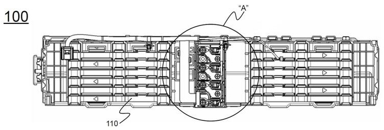
도 3은 본 발명의 하나의 실시예에 따른 전지모듈의 측면도이다;
도 4는 도 3의 A 부위의 확대도이다;
도 5는 도 3의 버스 바 장착용 부재의 모식도이다;
도 6은 도 5의 B 부위의 확대도이다.1 is a perspective view of a battery cell constituting a unit cell in the battery module of the present invention;
2 is a perspective view of a unit cell made up of the battery cells of FIG. 1;
3 is a side view of a battery module according to one embodiment of the present invention;
4 is an enlarged view of a portion A in Fig. 3;
5 is a schematic view of the bus bar mounting member of Fig. 3;
6 is an enlarged view of a portion B in Fig.
이하에서는, 본 발명의 실시예에 따른 도면을 참조하여 설명하지만, 이는 본 발명의 더욱 용이한 이해를 위한 것으로, 본 발명의 범주가 그것에 의해 한정되는 것은 아니다.Hereinafter, embodiments of the present invention will be described with reference to the accompanying drawings, but the present invention is not limited by the scope of the present invention.
도 1에는 본 발명의 전지모듈에서 단위셀을 구성하는 전지셀의 사시도가 도시되어 있고, 도 2에는 도 1의 전지셀로 구성된 단위셀의 사시도가 도시되어 있다. FIG. 1 is a perspective view of a battery cell constituting a unit cell in the battery module of the present invention, and FIG. 2 is a perspective view of a unit cell composed of the battery cell of FIG.
도 1 및 도 2를 참조하면, 전지셀(10)은 라미네이트 시트의 전지 케이스(13)에 전극 조립체(도시하지 않음)를 전해액(도시하지 않음)과 함께 내장하고, 외주면(14)을 실링한 구조로 이루어져 있다. 전극 탭들(11, 12)은 전지 케이스(13)의 일측에 형성되어 있다.1 and 2, the
단위셀(110)은, 전극단자들(112, 114)이 일측에 노출된 상태로 2개의 판상형 전지셀들(10)이 셀 커버(116)에 장착된 구조로 이루어져 있다. 단위셀의 셀 커버(116)는 전극단자들(112, 114) 부위를 제외하고 전지셀들(10)의 외면을 감싸도록 상호 결합되는 한 쌍의 외장 부재로 구성되며, 셀 커버(116) 내부의 전지셀들(10)은 동일 극성의 전극 탭들(11, 12)이 서로 접하면서 병렬 연결되도록 적층되어 있다. The
도 3에는 본 발명의 하나의 실시예에 따른 전지모듈의 측면도가 도시되어 있고, 도 4에는 도 3의 A 부위의 확대도가 도시되어 있으며, 도 5에는 도 3의 버스 바 장착용 부재의 사시도가 도시되어 있고, 도 6에는 도 5의 B 부위의 확대도가 도시되어 있다.FIG. 3 is a side view of a battery module according to one embodiment of the present invention. FIG. 4 is an enlarged view of a portion A in FIG. 3, and FIG. 5 is a perspective view And Fig. 6 is an enlarged view of a portion B in Fig.
도 3 내지 도 6과 도 2를 함께 참조하면, 전지모듈(100)은 복수의 단위셀들(110), 버스 바들(120), 링 단자들(130), 버스 바 장착용 부재(140), 및 BMS(도시하지 않음)로 이루어져 있다.3 to 6 and FIG. 2 together, the
복수의 단위셀들(110)은, 한 쌍의 단위셀들(110)이 전극단자들(112, 114)이 상호 대면하는 구조로 평면 상 배열된 상태에서, 이러한 단위셀들(110)이 지면으로부터 높이 방향으로 수직 배열되어 단위셀 적층체를 형성하고 있다.The plurality of
평면 상 연결된 단위셀들(110)은 병렬 연결되어 있고, 수직으로 배열된 단위셀들(110)들은 직렬 연결되어 있다.The planarly connected
단위셀들(110)의 전극단자들(112, 114)이 연결된 부위에 대응하는 부위에는 버스 바 장착용 부재(140)가 장착되어 있다. A bus
버스 바 장착용 부재(140)는 장방형 구조로 이루어져 있고, 외주면을 따라 측벽(145)이 돌출되어 형성되어 있다.The bus
버스 바 장착용 부재(140)의 내부에는 버스 바(120)에 대응하는 형상의 버스 바 장착용 홈들(141)이 형성되어 있고, 버스바 장착용 홈들(141)의 우측에는 링 단자들(130)의 회전을 방지하기 위한 링 단자 가이드들(142)이 형성되어 있다.Bus
단위셀들(110)의 전극단자들(112, 124)은 버스 바 장착용 부재(140) 방향 측의 단부가 절곡되어 있고, 전극단자들(112, 124)의 절곡된 단부와 버스 바(120)의 양측 단부에는 결합구들(도시하지 않음)이 형성되어 있다.The
전극단자들(112, 124) 및 버스 바(120)의 결합구들은 볼트(150)에 의해 전기적 및 기계적으로 체결되어 있다. 버스 바(120)와 볼트(150) 사이에는 링 단자(130)가 결합되어 있다.The
링 단자(130)는 단자 단부(131)와 단자 와이어(132)로 이루어져 있고, 버스 바 장착용 부재(140)는 링 단자 가이드(142)의 우측 단부 상단에 단자 와이어(132)를 고정하기 위한 후크(143)가 추가로 형성되어 있다.
The
본 발명이 속하는 분야에서 통상의 지식을 가진 자라면 상기 내용을 바탕으로 본 발명의 범주내에서 다양한 응용 및 변형을 가하는 것이 가능할 것이다.It will be understood by those of ordinary skill in the art that various changes in form and details may be made therein without departing from the spirit and scope of the invention as defined by the appended claims.
Claims (20)
단위셀들의 전기적 연결을 위한 버스 바들(busbars);
전압 측정을 위해 단위셀들의 전기적 연결 부위에 접속되어 있는 링 단자들(ring terminal); 및
단위셀들의 전기적 연결 부위에 대응하는 전지모듈의 외면에 장착되며, 링 단자들의 회전을 방지하기 위한 링 단자 가이드들(ring terminal guides)을 포함하고 있는 버스 바 장착용 부재;
를 포함하고 있고,
상기 링 단자는, 단위셀들의 직렬 연결 부위에 결합되는 단자 단부와, 상기 단자 단부에 연결된 단자 와이어를 포함하고 있고, 상기 링 단자 가이드는 단자 와이어를 정위치 고정하여 단자 단부의 회전을 억제하는 구조로 이루어지며,
상기 링 단자 가이드는 단자 와이어의 일측면 또는 양측면을 지지하는 돌출 구조로 이루어져 있고,
상기 버스 바 장착용 부재는, 상기 와이어를 고정 시키는 후크를 추가로 포함하고 있으며,
상기 후크는 상기 링 단자 가이드의 일측 단부로부터 상부로 이격되어 돌출되어 있는 것을 특징으로 하는 전지모듈.A battery module comprising a plurality of unit cells capable of charging and discharging,
Busbars for electrical connection of unit cells;
A ring terminal connected to an electrical connection portion of the unit cells for voltage measurement; And
A bus bar mounting member mounted on an outer surface of the battery module corresponding to an electrical connection portion of the unit cells and including ring terminal guides for preventing rotation of the ring terminals;
And,
The ring terminal includes a terminal end coupled to a series connection portion of unit cells and a terminal wire connected to the terminal end. The ring terminal guide has a structure Lt; / RTI >
The ring terminal guide has a protruding structure for supporting one side or both sides of the terminal wire,
The bus bar mounting member may further include a hook for fixing the wire,
And the hook is protruded upwardly from one end of the ring terminal guide.
상기 단위셀들은 전극단자들이 일측에 형성되어 있고, 한 쌍의 단위셀들이 전극단자 상호 대면 구조로 평면 배열된 상태에서, 이러한 단위셀들이 지면으로부터 높이 방향으로 수직 배열되어 단위셀 적층체를 형성하고 있고;
상기 단위셀 적층체의 일측면에 BMS(Battery Management System)가 장착되어 있으며;
상기 링 단자들은 BMS에 전기적으로 연결되어 있는 것을 특징으로 하는 전지모듈.The method according to claim 1,
The unit cells are formed on one side of the electrode terminals, and the unit cells are vertically arranged in the height direction from the ground in a state in which the pair of unit cells are arranged in plane-to-face relationship with each other, Have;
A BMS (Battery Management System) is mounted on one side of the unit cell stack;
And the ring terminals are electrically connected to the BMS.
상기 평면 배열된 한 쌍의 단위셀들은 병렬 연결되어 있고, 수직 배열된 단위셀들은 직렬 연결되어 있으며;
상기 링 단자들은 단위셀들의 직렬 연결 부위에 접속되어 있는 것을 특징으로 하는 전지모듈.The method according to claim 6,
Wherein the pair of unit cells arranged in a plane are connected in parallel and the unit cells arranged in a vertical direction are connected in series;
And the ring terminals are connected to a series connection portion of the unit cells.
Priority Applications (4)
| Application Number | Priority Date | Filing Date | Title |
|---|---|---|---|
| KR1020130100173A KR101747400B1 (en) | 2013-08-23 | 2013-08-23 | Battery Module Having Ring Terminal Guide |
| US14/909,003 US9806319B2 (en) | 2013-08-23 | 2014-08-21 | Battery module having ring terminal guide |
| PCT/KR2014/007763 WO2015026173A1 (en) | 2013-08-23 | 2014-08-21 | Battery module comprising ring terminal guides |
| EP14837209.7A EP3016176B1 (en) | 2013-08-23 | 2014-08-21 | Battery module comprising ring terminal guides |
Applications Claiming Priority (1)
| Application Number | Priority Date | Filing Date | Title |
|---|---|---|---|
| KR1020130100173A KR101747400B1 (en) | 2013-08-23 | 2013-08-23 | Battery Module Having Ring Terminal Guide |
Publications (2)
| Publication Number | Publication Date |
|---|---|
| KR20150022394A KR20150022394A (en) | 2015-03-04 |
| KR101747400B1 true KR101747400B1 (en) | 2017-06-27 |
Family
ID=52483891
Family Applications (1)
| Application Number | Title | Priority Date | Filing Date |
|---|---|---|---|
| KR1020130100173A Active KR101747400B1 (en) | 2013-08-23 | 2013-08-23 | Battery Module Having Ring Terminal Guide |
Country Status (4)
| Country | Link |
|---|---|
| US (1) | US9806319B2 (en) |
| EP (1) | EP3016176B1 (en) |
| KR (1) | KR101747400B1 (en) |
| WO (1) | WO2015026173A1 (en) |
Cited By (1)
| Publication number | Priority date | Publication date | Assignee | Title |
|---|---|---|---|---|
| WO2023085726A1 (en) * | 2021-11-12 | 2023-05-19 | 주식회사 엘지에너지솔루션 | Battery module and battery pack comprising same |
Families Citing this family (3)
| Publication number | Priority date | Publication date | Assignee | Title |
|---|---|---|---|---|
| KR102017226B1 (en) * | 2015-10-02 | 2019-09-02 | 주식회사 엘지화학 | Battery Module Comprising Cover Assembly Capable of Alleviating Torsion Stress in Screw Fastening Portion |
| KR102404239B1 (en) * | 2018-09-10 | 2022-05-30 | 주식회사 엘지에너지솔루션 | ICB assembly, battery module comprising the same and method for fabricating the battery module |
| JP7590130B2 (en) * | 2020-07-17 | 2024-11-26 | 株式会社オートネットワーク技術研究所 | Wiring Module |
Citations (1)
| Publication number | Priority date | Publication date | Assignee | Title |
|---|---|---|---|---|
| JP2012248511A (en) * | 2011-05-31 | 2012-12-13 | Auto Network Gijutsu Kenkyusho:Kk | Battery pack wiring module |
Family Cites Families (10)
| Publication number | Priority date | Publication date | Assignee | Title |
|---|---|---|---|---|
| JP4823535B2 (en) | 2005-02-14 | 2011-11-24 | 矢崎総業株式会社 | Battery connection plate |
| KR100948002B1 (en) * | 2006-03-06 | 2010-03-18 | 주식회사 엘지화학 | Medium and large battery module |
| US7303448B1 (en) * | 2006-05-24 | 2007-12-04 | East Penn Manufacturing Co., Inc. | Battery terminal connector with reversible clamp lever |
| JP5465440B2 (en) * | 2009-01-28 | 2014-04-09 | 三洋電機株式会社 | Assembled battery |
| EP2469626B1 (en) * | 2009-08-18 | 2018-01-10 | Yazaki Corporation | Power-supply device and battery connector |
| US8803477B2 (en) * | 2010-09-21 | 2014-08-12 | Electricab Corporation | Battery module for high-current rapid charging |
| JP5651079B2 (en) * | 2011-07-21 | 2015-01-07 | 矢崎総業株式会社 | Battery pack controller |
| KR101400083B1 (en) * | 2011-08-10 | 2014-05-27 | 주식회사 엘지화학 | Unit Module of Improved Safety by Polymer Resin Filling |
| JP5772524B2 (en) * | 2011-11-11 | 2015-09-02 | 株式会社オートネットワーク技術研究所 | Battery wiring module |
| JP5382149B2 (en) * | 2012-01-12 | 2014-01-08 | 株式会社オートネットワーク技術研究所 | Wiring module |
-
2013
- 2013-08-23 KR KR1020130100173A patent/KR101747400B1/en active Active
-
2014
- 2014-08-21 WO PCT/KR2014/007763 patent/WO2015026173A1/en not_active Ceased
- 2014-08-21 US US14/909,003 patent/US9806319B2/en active Active
- 2014-08-21 EP EP14837209.7A patent/EP3016176B1/en active Active
Patent Citations (1)
| Publication number | Priority date | Publication date | Assignee | Title |
|---|---|---|---|---|
| JP2012248511A (en) * | 2011-05-31 | 2012-12-13 | Auto Network Gijutsu Kenkyusho:Kk | Battery pack wiring module |
Cited By (1)
| Publication number | Priority date | Publication date | Assignee | Title |
|---|---|---|---|---|
| WO2023085726A1 (en) * | 2021-11-12 | 2023-05-19 | 주식회사 엘지에너지솔루션 | Battery module and battery pack comprising same |
Also Published As
| Publication number | Publication date |
|---|---|
| WO2015026173A1 (en) | 2015-02-26 |
| EP3016176A1 (en) | 2016-05-04 |
| KR20150022394A (en) | 2015-03-04 |
| EP3016176A4 (en) | 2016-08-03 |
| US9806319B2 (en) | 2017-10-31 |
| EP3016176B1 (en) | 2019-08-21 |
| US20160181586A1 (en) | 2016-06-23 |
Similar Documents
| Publication | Publication Date | Title |
|---|---|---|
| KR101805757B1 (en) | Battery Module Assembly Having Protruded Communication Terminals of BMS in Front thereof | |
| KR101586668B1 (en) | Battery Module Assembly Including Sub-Modules Inside | |
| KR101749721B1 (en) | Battery Module Assembly Having Fuse Assembly | |
| US11342597B2 (en) | Battery pack including noise reduction member | |
| KR101653307B1 (en) | A Battery Module Assembly including Unit-Modules | |
| KR101815876B1 (en) | Battery pack with apparatus to prevent surge current | |
| KR101746127B1 (en) | Stacking Type Battery Module of Series Connection Structure | |
| EP2624334A2 (en) | Battery pack having a compact structure | |
| KR101747398B1 (en) | Stacking Type Battery Module of Parallel Connection Structure | |
| US9379367B2 (en) | Stacking type battery pack having connecting member made of different metals | |
| KR20150033551A (en) | Battery Pack Having Inserted-typed BMS Assembly | |
| KR20150022389A (en) | Battery Pack for Electric Power Storage Device | |
| KR20150022394A (en) | Battery Module Having Ring Terminal Guide | |
| KR101750088B1 (en) | Battery Module Having Ring Terminal Fixing Structure | |
| KR101666376B1 (en) | Harness cover | |
| JP2015185414A (en) | battery system | |
| US20150037643A1 (en) | Safety device for battery pack having inserted-typed disconnect member | |
| CN209087953U (en) | A kind of support bracket fastened lead acid storage battery for traction group easy to disassemble | |
| CN205231135U (en) | Automobile -used lithium ion power batteries module | |
| KR101541367B1 (en) | Energy Storage System Including Switch for Safety | |
| KR101802865B1 (en) | Battery Protection Module and Battery Pack Comprising the Same |
Legal Events
| Date | Code | Title | Description |
|---|---|---|---|
| PA0109 | Patent application |
Patent event code: PA01091R01D Comment text: Patent Application Patent event date: 20130823 |
|
| A201 | Request for examination | ||
| PA0201 | Request for examination |
Patent event code: PA02012R01D Patent event date: 20141126 Comment text: Request for Examination of Application Patent event code: PA02011R01I Patent event date: 20130823 Comment text: Patent Application |
|
| PG1501 | Laying open of application | ||
| E902 | Notification of reason for refusal | ||
| PE0902 | Notice of grounds for rejection |
Comment text: Notification of reason for refusal Patent event date: 20161122 Patent event code: PE09021S01D |
|
| AMND | Amendment | ||
| E601 | Decision to refuse application | ||
| PE0601 | Decision on rejection of patent |
Patent event date: 20170415 Comment text: Decision to Refuse Application Patent event code: PE06012S01D Patent event date: 20161122 Comment text: Notification of reason for refusal Patent event code: PE06011S01I |
|
| X091 | Application refused [patent] | ||
| AMND | Amendment | ||
| PX0901 | Re-examination |
Patent event code: PX09011S01I Patent event date: 20170415 Comment text: Decision to Refuse Application Patent event code: PX09012R01I Patent event date: 20170104 Comment text: Amendment to Specification, etc. |
|
| PX0701 | Decision of registration after re-examination |
Patent event date: 20170516 Comment text: Decision to Grant Registration Patent event code: PX07013S01D Patent event date: 20170427 Comment text: Amendment to Specification, etc. Patent event code: PX07012R01I Patent event date: 20170415 Comment text: Decision to Refuse Application Patent event code: PX07011S01I Patent event date: 20170104 Comment text: Amendment to Specification, etc. Patent event code: PX07012R01I |
|
| X701 | Decision to grant (after re-examination) | ||
| GRNT | Written decision to grant | ||
| PR0701 | Registration of establishment |
Comment text: Registration of Establishment Patent event date: 20170608 Patent event code: PR07011E01D |
|
| PR1002 | Payment of registration fee |
Payment date: 20170608 End annual number: 3 Start annual number: 1 |
|
| PG1601 | Publication of registration | ||
| FPAY | Annual fee payment |
Payment date: 20200421 Year of fee payment: 4 |
|
| PR1001 | Payment of annual fee |
Payment date: 20200421 Start annual number: 4 End annual number: 4 |
|
| FPAY | Annual fee payment |
Payment date: 20210518 Year of fee payment: 5 |
|
| PR1001 | Payment of annual fee |
Payment date: 20210518 Start annual number: 5 End annual number: 5 |
|
| FPAY | Annual fee payment |
Payment date: 20220502 Year of fee payment: 6 |
|
| PR1001 | Payment of annual fee |
Payment date: 20220502 Start annual number: 6 End annual number: 6 |
|
| PR1001 | Payment of annual fee |
Payment date: 20240319 Start annual number: 8 End annual number: 8 |