EP2468945A1 - Haushaltswäschetrockner mit Wärmepumpe - Google Patents
Haushaltswäschetrockner mit Wärmepumpe Download PDFInfo
- Publication number
- EP2468945A1 EP2468945A1 EP10197042A EP10197042A EP2468945A1 EP 2468945 A1 EP2468945 A1 EP 2468945A1 EP 10197042 A EP10197042 A EP 10197042A EP 10197042 A EP10197042 A EP 10197042A EP 2468945 A1 EP2468945 A1 EP 2468945A1
- Authority
- EP
- European Patent Office
- Prior art keywords
- refrigerant
- heat exchanger
- temperature
- pressure
- outlet
- Prior art date
- Legal status (The legal status is an assumption and is not a legal conclusion. Google has not performed a legal analysis and makes no representation as to the accuracy of the status listed.)
- Granted
Links
- 239000003507 refrigerant Substances 0.000 claims abstract description 1940
- 238000001816 cooling Methods 0.000 claims abstract description 265
- 230000000284 resting effect Effects 0.000 claims abstract description 7
- 238000011017 operating method Methods 0.000 claims description 35
- 229920006395 saturated elastomer Polymers 0.000 claims description 32
- 230000003134 recirculating effect Effects 0.000 claims description 23
- 239000011555 saturated liquid Substances 0.000 claims description 13
- 238000012546 transfer Methods 0.000 claims description 11
- 238000009423 ventilation Methods 0.000 claims description 3
- 230000005465 channeling Effects 0.000 claims description 2
- 230000000875 corresponding effect Effects 0.000 description 36
- 238000001704 evaporation Methods 0.000 description 34
- 230000008020 evaporation Effects 0.000 description 34
- 230000004913 activation Effects 0.000 description 33
- 230000009849 deactivation Effects 0.000 description 30
- 239000007788 liquid Substances 0.000 description 29
- 238000011217 control strategy Methods 0.000 description 24
- 230000001276 controlling effect Effects 0.000 description 23
- 238000001035 drying Methods 0.000 description 11
- 238000009834 vaporization Methods 0.000 description 9
- 230000008016 vaporization Effects 0.000 description 9
- 238000010438 heat treatment Methods 0.000 description 8
- 230000002596 correlated effect Effects 0.000 description 6
- 238000011068 loading method Methods 0.000 description 6
- 239000000203 mixture Substances 0.000 description 6
- 238000007791 dehumidification Methods 0.000 description 5
- 238000000034 method Methods 0.000 description 5
- 239000012530 fluid Substances 0.000 description 4
- 238000005259 measurement Methods 0.000 description 4
- 230000008569 process Effects 0.000 description 4
- 230000009467 reduction Effects 0.000 description 4
- 230000006835 compression Effects 0.000 description 3
- 238000007906 compression Methods 0.000 description 3
- 238000009833 condensation Methods 0.000 description 3
- 230000005494 condensation Effects 0.000 description 3
- 238000011144 upstream manufacturing Methods 0.000 description 3
- BIIBYWQGRFWQKM-JVVROLKMSA-N (2S)-N-[4-(cyclopropylamino)-3,4-dioxo-1-[(3S)-2-oxopyrrolidin-3-yl]butan-2-yl]-2-[[(E)-3-(2,4-dichlorophenyl)prop-2-enoyl]amino]-4,4-dimethylpentanamide Chemical compound CC(C)(C)C[C@@H](C(NC(C[C@H](CCN1)C1=O)C(C(NC1CC1)=O)=O)=O)NC(/C=C/C(C=CC(Cl)=C1)=C1Cl)=O BIIBYWQGRFWQKM-JVVROLKMSA-N 0.000 description 2
- 239000006096 absorbing agent Substances 0.000 description 2
- 238000013459 approach Methods 0.000 description 2
- 230000007423 decrease Effects 0.000 description 2
- 230000000694 effects Effects 0.000 description 2
- 230000008859 change Effects 0.000 description 1
- AFYPFACVUDMOHA-UHFFFAOYSA-N chlorotrifluoromethane Chemical compound FC(F)(F)Cl AFYPFACVUDMOHA-UHFFFAOYSA-N 0.000 description 1
- 238000006073 displacement reaction Methods 0.000 description 1
- 238000005265 energy consumption Methods 0.000 description 1
- 230000002349 favourable effect Effects 0.000 description 1
- 238000001914 filtration Methods 0.000 description 1
- 238000010348 incorporation Methods 0.000 description 1
- 238000003780 insertion Methods 0.000 description 1
- 230000037431 insertion Effects 0.000 description 1
- 230000003993 interaction Effects 0.000 description 1
- 238000004519 manufacturing process Methods 0.000 description 1
- 239000002245 particle Substances 0.000 description 1
- XLYOFNOQVPJJNP-UHFFFAOYSA-N water Substances O XLYOFNOQVPJJNP-UHFFFAOYSA-N 0.000 description 1
Images


Classifications
-
- F—MECHANICAL ENGINEERING; LIGHTING; HEATING; WEAPONS; BLASTING
- F26—DRYING
- F26B—DRYING SOLID MATERIALS OR OBJECTS BY REMOVING LIQUID THEREFROM
- F26B23/00—Heating arrangements
- F26B23/001—Heating arrangements using waste heat
- F26B23/002—Heating arrangements using waste heat recovered from dryer exhaust gases
- F26B23/005—Heating arrangements using waste heat recovered from dryer exhaust gases using a closed cycle heat pump system ; using a heat pipe system
-
- D—TEXTILES; PAPER
- D06—TREATMENT OF TEXTILES OR THE LIKE; LAUNDERING; FLEXIBLE MATERIALS NOT OTHERWISE PROVIDED FOR
- D06F—LAUNDERING, DRYING, IRONING, PRESSING OR FOLDING TEXTILE ARTICLES
- D06F58/00—Domestic laundry dryers
- D06F58/20—General details of domestic laundry dryers
- D06F58/206—Heat pump arrangements
Definitions
- the present invention relates to a home laundry dryer.
- the present invention relates to a rotary-drum, heat-pump type, home laundry dryer, to which the following description refers purely by way of example without implying any loss of generality.
- today's rotary-drum home laundry dryers comprise: a substantially parallelepiped-shaped outer boxlike casing structured for resting on the floor; a substantially cylindrical, hollow revolving drum structured for internally housing the laundry to be dried, and which is housed in axially rotating manner inside the casing to rotate about its horizontally-oriented longitudinal axis, directly facing a laundry loading/unloading through opening realized in the front wall of the casing; a door hinged to the front wall of the casing to rotate to and from a closing position in which the door rests completely against the front wall of the casing to close the laundry loading/unloading opening and airtight seal the revolving drum; and an electrically-powered motor assembly structured for driving into rotation the revolving drum about its longitudinal axis inside the casing.
- Rotary-drum home laundry dryers of the above type are also provided with a closed-circuit, hot-air generator which is designed to circulate inside the revolving drum a stream of hot air having a low moisture content, and which flows through the revolving drum and over the laundry inside the drum to rapidly dry said laundry; and with an electronic central control unit which controls both the motor assembly and the hot-air generator to perform one of the user-selectable drying cycles stored in the same central control unit.
- the closed-circuit, hot-air generator comprises an air recirculating conduit having its two ends connected to the revolving drum, on opposite sides of the latter; an electric centrifugal fan located along the air recirculating conduit to produce, inside the latter, an airflow which flows through the revolving drum; and finally a heat-pump assembly having its two heat exchangers located one after the other, along the air recirculating conduit.
- the heat-pump assembly comprises a first air/refrigerant heat exchanger which provides for rapidly cooling the airflow arriving from the revolving drum to condense and restrain the surplus moisture in the airflow; a second air/refrigerant heat exchanger which provides for rapidly heating the airflow arriving from the first heat exchanger and directed back to the revolving drum, so that the airflow re-entering into the revolving drum is heated rapidly to a temperature higher than or equal to that of the airflow coming out of the drum; and an electrically-powered refrigerant compressing device which is interposed between the refrigerant-outlet of the first air/refrigerant heat exchanger and the refrigerant-inlet of the second air/refrigerant heat exchanger, and it is structured to continuously compress the gaseous-state refrigerant directed towards the second heat exchanger so that refrigerant pressure and temperature are much higher at the refrigerant-inlet of the second heat exchanger than at the refrigerant-out
- the first air/refrigerant heat exchanger is traditionally called “evaporator”, and it is structured so that the airflow arriving from the revolving drum and the low-pressure and low-temperature refrigerant directed to the suction of the refrigerant compressing device can flow through it simultaneously, allowing the refrigerant having a temperature lower than that of the airflow, to absorb heat from the airflow, thus causing condensation of the surplus moisture in the airflow arriving from the revolving drum;
- the second air/refrigerant heat exchanger is traditionally called “condenser”, and it is structured so that the airflow directed back into the revolving drum and the high-pressure and high-temperature refrigerant arriving from the delivery of the refrigerant compressing device can flow through it simultaneously, allowing the refrigerant having a temperature greater than that of the airflow to release heat to the airflow, thus rapidly heating the airflow directed back into the drum.
- the heat-pump assembly is provided with a refrigerant expansion device which is interposed between the refrigerant-outlet of the condenser and the refrigerant-inlet of the evaporator, and it is structured so as to cause a rapid expansion of the refrigerant directed towards the evaporator so that refrigerant pressure and temperature are much higher at the refrigerant-outlet of the condenser than at the refrigerant-inlet of the evaporator.
- the air dehumidification is very low at beginning of the drying cycle (low moist quantity extracted from the air) and it increases as the drying cycle proceeds, thus it takes a lot of time to the heat-pump assembly to reach the steady-state full-power working condition in which the temperature of the airflow circulating into the revolving drum reaches the highest value and remains substantially constant to said highest value.
- a second problem correlated to the use of a heat-pump type hot-air generators is the intrinsically unbalanced energy balance between the heat absorbed from the airflow in the evaporator, i.e. in the first air/ refrigerant heat exchanger, and the heat supplied to the airflow in the condenser, i.e. in the second air/ refrigerant heat exchanger, when the hot-air generator is in the steady-state full-power working condition.
- the air flowing along the air recirculating conduit of the hot-air generator should give off and absorb approximately the same quantity of heat to return at the same temperature as when coming out of revolving drum.
- the air/refrigerant heat exchange in the condenser i.e. in the second heat exchanger
- the refrigerant circulates in close loop also in the evaporator, i.e. in the first heat exchanger
- the reduced air/refrigerant heat exchange capacity leads to a consequent limitation of the air cooling capacity of the refrigerant in the evaporator, where much more energy could be exchanged due to the dehumidification process.
- the latent condensation heat of the water, i.e. of the moisture in fact is very high.
- Another applicant solution envisage the use of a third air/refrigerant heat exchanger in series to the second air/refrigerant heat exchanger, i.e. to the condenser, immediately downstream the latter.
- This third air/refrigerant heat exchanger is cooled by a cold airflow that an auxiliary electric fan draws from the outside of the laundry dryer, so as to slightly cool down the high-temperature and high-pressure refrigerant directed towards the refrigerant expansion device.
- This second solution significantly increases the air/refrigerant heat exchange capacity at high-pressure side of heat-pump assembly and, as a consequence, significantly increases the available air cooling capacity of the refrigerant in the first heat exchanger, i.e. in the evaporator.
- the main drawback of this second solution is that the air cooling capacity of the refrigerant in the evaporator, i.e. in the first air/refrigerant heat exchanger, is strictly limited by the fact that the refrigerant must be completely vaporized, i.e. completely in gaseous state, at suction of refrigerant compressing device, and the use of the third air/refrigerant heat exchanger may cause the refrigerant to be still partially in liquid state when coming out of the evaporator, i.e. of the first air/refrigerant heat exchanger, directed to the suction of the refrigerant compressing device, with all problems concerned.
- the heat absorbed from the airflow arriving from the revolving drum is not enough to completely vaporize the refrigerant flowing along the evaporator.
- an excessive cooling of the refrigerant at the high-pressure side of the heat-pump assembly can deteriorate the refrigerant "vapor quality" at suction of the refrigerant compressing device, up to irreparably damage the structural integrity of the refrigerant compressing device.
- a third air/refrigerant heat exchanger that cools down the refrigerant too much, may cause the refrigerant "vapor quality" at suction of the refrigerant compressing device to be below 1.
- the refrigerant "vapor quality" at suction of the refrigerant compressing device in fact, is the ratio, determined at suction of the refrigerant compressing device, between the amount of refrigerant in gaseous state and the total amount of refrigerant (i.e. both in liquid and gaseous state).
- a "vapor quality” equal to 1 means that all refrigerant is in gaseous state (saturated vapor refrigerant or superheated refrigerant), whereas a "vapor quality” equal to 0 means that all refrigerant is in liquid state (saturated liquid refrigerant or sub-cooled refrigerant).
- Aim of the present invention is to improve efficiency and performances of the heat-pump type, hot-air generator of today's rotary-drum home laundry dryers, and to eliminate the drawbacks referred above.
- a home laundry dryer as specified in Claim 1 and preferably, though not necessarily, in any one of the dependant claims.
- a laundry dryer comprising an outer boxlike casing structured for resting on the floor and, inside the casing, a laundry container structured for housing the laundry to be dried, and a closed-circuit, hot-air generator structured to circulate through the laundry container a stream of hot air;
- the hot-air generator in turn comprising: an air recirculating conduit having its two ends connected to the laundry container; air circulating means structured to produce, inside the air recirculating conduit, an airflow which flows through said laundry container; and a heat-pump assembly structured to cool the airflow coming out from the laundry container for condensing the moisture in said airflow, and then to heat the airflow returning back into the laundry container;
- said heat-pump assembly comprising: a first air/refrigerant heat exchanger which is located along the air recirculating conduit, and it is structured for transferring heat from the airflow arriving from the laundry container to the refrigerant so as to condense the moisture in the airflow; a second air/re
- the central control unit is structured for controlling said refrigerant cooling means or refrigerant flow-rate adjusting means so as to maintain the "thermodynamic quality ratio" of the refrigerant at refrigerant-outlet of the first heat exchanger between 0,7 and 1,15, or between 1 and 1,15.
- the central control unit is structured for controlling said refrigerant cooling means or refrigerant flow-rate adjusting means so as to maintain the "thermodynamic quality ratio" of the refrigerant at refrigerant-outlet of the first heat exchanger between 0,7 and 1,07, or between 1 and 1,07.
- the central control unit is structured for controlling said refrigerant cooling means or refrigerant flow-rate adjusting means so as to maintain the "thermodynamic quality ratio" of the refrigerant at refrigerant-outlet of the first heat exchanger between 0,7 and 1,03, or between 1 and 1,03.
- said at least one physical quantity is the temperature and/or pressure of the refrigerant at refrigerant-inlet or at refrigerant-outlet of said first air/refrigerant heat exchanger; and/or the temperature rise or drop of the refrigerant flowing through said first air/refrigerant heat exchanger.
- said at least one physical quantity is the temperature and/or pressure of the refrigerant at low-pressure refrigerant inlet or at low-pressure refrigerant outlet of the low-pressure side of said refrigerant/ refrigerant heat exchanger; and/or the temperature and/or pressure of the refrigerant at high-pressure refrigerant inlet or at high-pressure refrigerant outlet of the high-pressure side of said refrigerant/refrigerant heat exchanger; and/or the temperature rise of the refrigerant flowing through the low-pressure side of said refrigerant/refrigerant heat exchanger; and/or the temperature drop of the refrigerant flowing through the high-pressure side of said refrigerant/refrigerant heat exchanger.
- said at least one physical quantity is the temperature and/or pressure of the refrigerant at suction and/or at delivery of said refrigerant compressing device.
- said at least one physical quantity is the temperature and/or pressure of the refrigerant at refrigerant inlet or at refrigerant outlet of said second air/refrigerant heat exchanger.
- said at least one physical quantity is the temperature and/or moisture degree of the airflow entering into, or coming out of, said laundry container.
- the refrigerant cooling means comprise a third air/refrigerant heat exchanger which is connected in series to the second air/refrigerant heat exchanger, and it is structured so as to selectively cool down the high-pressure refrigerant directed towards the refrigerant expansion device.
- said refrigerant cooling means additionally comprise an auxiliary ventilation device which is structured for channeling, on command, a stream of cooling air towards the body of said third air/ refrigerant heat exchanger.
- said refrigerant flow-rate adjusting means comprise a variable speed refrigerant compressing device, or an electrically-operated refrigerant expansion valve, or an electrically-operated multiple capillary-tube expansion system.
- said detecting means comprise sensor means structured for detecting the temperature and/or pressure of the refrigerant at low-pressure refrigerant inlet of said refrigerant/refrigerant heat exchanger, and/or at low-pressure refrigerant outlet of said refrigerant/ refrigerant heat exchanger, and/or at high-pressure refrigerant inlet of said refrigerant/refrigerant heat exchanger, and/or at high-pressure refrigerant outlet of said refrigerant/ refrigerant heat exchanger.
- an operating method of a laundry dryer comprising an outer boxlike casing structured for resting on the floor and, inside the casing, a laundry container structured for housing the laundry to be dried, and a closed-circuit, hot-air generator structured to circulate through the laundry container, on command, a stream of hot air;
- the hot-air generator being provided with a heat-pump assembly structured to cool the airflow coming out from the laundry container for condensing the moisture in said airflow, and then to heat the airflow returning back into the laundry container;
- said heat-pump assembly comprising: a first air/refrigerant heat exchanger which is structured for transferring heat from the airflow arriving from the laundry container to a low-pressure refrigerant so as to condense the moisture in the airflow; and a second air/refrigerant heat exchanger which is structured for transferring heat from a high-pressure refrigerant to the airflow directed back into the laundry container so as to heat said airflow;
- said refrigerant cooling means or refrigerant flow-rate adjusting means are controlled so as to selectively maintain between 0,7 and 1,15, or between 1 and 1,15, the "thermodynamic quality ratio" of the refrigerant at refrigerant-outlet of the first heat exchanger.
- said refrigerant cooling means or refrigerant flow-rate adjusting means are controlled so as to selectively maintain between 0,7 and 1,07 or between 1 and 1,07, the "thermodynamic quality ratio" of the refrigerant at refrigerant-outlet of the first heat exchanger.
- said refrigerant cooling means or refrigerant flow-rate adjusting means are controlled so as to selectively maintain between 0,7 and 1,03, or between 1 and 1,03, the "thermodynamic quality ratio" of the refrigerant at refrigerant-outlet of the first heat exchanger.
- said at least one physical quantity is the temperature and/or pressure of the refrigerant at refrigerant-inlet or at refrigerant-outlet of said first air/refrigerant heat exchanger; and/or the temperature rise or drop of the refrigerant flowing through said first air/refrigerant heat exchanger.
- said at least one physical quantity is the temperature and/or pressure of the refrigerant at low-pressure refrigerant inlet or at low-pressure refrigerant outlet of the low-pressure side of said refrigerant/refrigerant heat exchanger; and/or the temperature and/or pressure of the refrigerant at high-pressure refrigerant inlet or at high-pressure refrigerant outlet of the high-pressure side of said refrigerant/refrigerant heat exchanger; and/or the temperature rise of the refrigerant flowing through the low-pressure side of said refrigerant/refrigerant heat exchanger; and/or the temperature drop of the refrigerant flowing through the high-pressure side of said refrigerant/refrigerant heat exchanger
- said at least one physical quantity is the temperature and/or pressure of the refrigerant at suction and/or at delivery of said refrigerant compressing device.
- said at least one physical quantity is the temperature and/or pressure of the refrigerant at refrigerant inlet or at refrigerant outlet of said second air/refrigerant heat exchanger.
- said at least one physical quantity is the temperature and/or moisture degree of the airflow entering into, or coming out of, said laundry container.
- the step of measuring the current value of said at least one physical quantity comprises the step of measuring the current pressure and temperature of the refrigerant at refrigerant-outlet of the first heat exchanger; and in that the step of controlling said refrigerant cooling means or refrigerant flow-rate adjusting means comprises the step of calculating the saturation temperature of the refrigerant on the basis of the current refrigerant pressure, and the step of driving said refrigerant cooling means or refrigerant flow-rate adjusting means so as to keep the temperature of the refrigerant at refrigerant-outlet of said first heat exchanger within a predetermined first temperature range encompassing the calculated refrigerant saturation temperature.
- the step of driving refrigerant cooling means or refrigerant flow-rate adjusting means comprises the step of either
- the step of measuring the current value of said at least one physical quantity comprises the step of measuring the current pressure and temperature of the refrigerant at low-pressure refrigerant outlet of said refrigerant/refrigerant heat exchanger; and in that the step of controlling said refrigerant cooling means or refrigerant flow-rate adjusting means comprises the step of calculating the saturation temperature of the refrigerant on the basis of the current refrigerant pressure, and the step of driving said refrigerant cooling means or refrigerant flow-rate adjusting means so as to keep the temperature of the refrigerant at low-pressure refrigerant outlet of the auxiliary refrigerant/refrigerant heat exchanger within a predetermined second temperature range located above said refrigerant saturation temperature.
- the step of driving said refrigerant cooling means or refrigerant flow-rate adjusting means comprises the step of either
- the step of measuring the current value of said at least one physical quantity comprises the steps of measuring the temperature rise of the refrigerant flowing through the low-pressure side of said refrigerant/refrigerant heat exchanger, and of measuring the temperature drop of the refrigerant flowing through the high-pressure side of said refrigerant/ refrigerant heat exchanger; and in that the step of controlling said refrigerant cooling means or refrigerant flow-rate adjusting means comprises the step of driving said refrigerant cooling means or refrigerant flow-rate adjusting means so as to keep the difference between the temperature rise of the refrigerant flowing in the low-pressure side of the refrigerant/refrigerant heat exchanger and the temperature drop of the refrigerant flowing in the high-pressure side of the refrigerant/refrigerant heat exchanger, within a predetermined third temperature range.
- the step of driving said refrigerant cooling means or refrigerant flow-rate adjusting means comprises the step of either
- the step of measuring the current value of said at least one physical quantity comprises the step of measuring the temperature rise or drop of the refrigerant flowing through the first air/refrigerant heat exchanger; and in that the step of controlling said refrigerant cooling means or refrigerant flow-rate adjusting means comprises the step of driving said refrigerant cooling means or refrigerant flow-rate adjusting means so as to keep the temperature rise or drop of the refrigerant flowing through said first air/refrigerant heat exchanger within a predetermined fourth temperature range.
- said fourth temperature range is included among -10°C and +15°C.
- the step of driving said refrigerant cooling means or refrigerant flow-rate adjusting means comprises the step of either
- the step of measuring the current value of said at least one physical quantity comprises also the step of measuring the temperature drop of the refrigerant flowing through the high-pressure side of said refrigerant/refrigerant heat exchanger; and in that the step of controlling said refrigerant cooling means or refrigerant flow-rate adjusting means comprises also the step of driving said refrigerant cooling means or refrigerant flow-rate adjusting means so as to also keep the temperature drop of the refrigerant flowing through the high-pressure side of the refrigerant/refrigerant heat exchanger within a fifth temperature range.
- the step of driving said refrigerant cooling means or refrigerant flow-rate adjusting means comprises the step of either
- the step of measuring the current value of said at least one physical quantity comprises also the step of measuring the temperature rise of the refrigerant flowing through the low-pressure side of said refrigerant/refrigerant heat exchanger; and in that the step of controlling said refrigerant cooling means or refrigerant flow-rate adjusting means comprises also the step of driving said refrigerant cooling means or refrigerant flow-rate adjusting means so as to also keep the temperature rise of the refrigerant flowing through the low-pressure side of said refrigerant/refrigerant heat exchanger within a sixth temperature range whose upper and lower ends are located above that of said fourth temperature range.
- step of driving said refrigerant cooling means or refrigerant flow-rate adjusting means comprises the step of either
- the step of measuring the current value of said at least one physical quantity comprises the step of measuring the temperature drop of the refrigerant flowing through the high-pressure side of said refrigerant/refrigerant heat exchanger; and in that the step of controlling said refrigerant cooling means or refrigerant flow-rate adjusting means comprises the step of driving said refrigerant cooling means or refrigerant flow-rate adjusting means so as to keep the temperature drop of the refrigerant flowing through the high-pressure side of the refrigerant/ refrigerant heat exchanger within a seventh temperature range.
- the step of measuring the current value of said at least one physical quantity comprises the step of measuring the temperature rise of the refrigerant flowing through the low-pressure side of said refrigerant/refrigerant heat exchanger; and in that the step of controlling said refrigerant cooling means or refrigerant flow-rate adjusting means comprises the step of driving said refrigerant cooling means or refrigerant flow-rate adjusting means so as to keep the temperature rise of the refrigerant flowing through the low-pressure side of the refrigerant/ refrigerant heat exchanger within a eighth temperature range.
- the step of measuring the current value of said at least one physical quantity comprises the step of measuring the refrigerant temperature at low-pressure refrigerant outlet of the refrigerant/ refrigerant heat exchanger; and in that the step of controlling said refrigerant cooling means or refrigerant flow-rate adjusting means comprises the step of driving said refrigerant cooling means or refrigerant flow-rate adjusting means so as to keep the refrigerant temperature at low-pressure refrigerant outlet of said refrigerant/ refrigerant heat exchanger within a predetermined ninth temperature range.
- the step of measuring the current value of said at least one physical quantity comprises the step of measuring the refrigerant temperature at refrigerant inlet of the second air/ refrigerant heat exchanger; and in that the step of controlling said refrigerant cooling means or refrigerant flow-rate adjusting means comprises the step of driving said refrigerant cooling means or refrigerant flow-rate adjusting means so as to keep the refrigerant temperature at refrigerant inlet of said second air/refrigerant heat exchanger within a predetermined tenth temperature range.
- the step of measuring the current value of said at least one physical quantity comprises the step of measuring the refrigerant temperature at delivery of the refrigerant compressing device; and in that the step of controlling said refrigerant cooling means or refrigerant flow-rate adjusting means comprises the step of driving said refrigerant cooling means or refrigerant flow-rate adjusting means so as to keep the refrigerant temperature at delivery of said refrigerant compressing device within a predetermined tenth temperature range.
- the step of measuring the current value of said at least one physical quantity comprises the step of measuring the refrigerant temperature at high-pressure refrigerant inlet of the refrigerant/ refrigerant heat exchanger; and in that the step of controlling said refrigerant cooling means or refrigerant flow-rate adjusting means comprises the step of driving said refrigerant cooling means or refrigerant flow-rate adjusting means so as to keep the refrigerant temperature at high-pressure refrigerant inlet of said refrigerant/refrigerant heat exchanger within a predetermined eleventh temperature range.
- the step of measuring the current value of said at least one physical quantity comprises the step of measuring the refrigerant temperature at high-pressure refrigerant outlet of the refrigerant/ refrigerant heat exchanger; and in that the step of controlling said refrigerant cooling means or refrigerant flow-rate adjusting means comprises the step of driving said refrigerant cooling means or refrigerant flow-rate adjusting means so as to keep the refrigerant temperature at high-pressure refrigerant outlet of said refrigerant/ refrigerant heat exchanger within a predetermined twelfth temperature range.
- the step of measuring the current value of said at least one physical quantity comprises the step of measuring the temperature of the airflow entering into the laundry container; and in that the step of controlling said refrigerant cooling means or refrigerant flow-rate adjusting means comprises the step of driving said refrigerant cooling means or refrigerant flow-rate adjusting means so as to keep the temperature of said airflow within a predetermined thirteenth temperature range.
- number 1 indicates as a whole a heat-pump type, home laundry dryer which comprises:
- heat-pump type, closed-circuit hot-air generator 5 provides for gradually drawing air from laundry container 3; extracting and retaining the surplus moisture from the hot air drawn from laundry container 3; heating the dehumidified air to a predetermined temperature, normally higher than or equal to the temperature of the air arriving from laundry container 3; and feeding the heated, dehumidified air back into laundry container 3, where it flows over, to rapidly dry, the laundry inside the container.
- Hot-air generator 5 therefore, provides for continuously dehumidifying and heating the air circulating inside laundry container 3 to rapidly dry the laundry inside the container.
- laundry dryer 1 is preferably a rotary-drum, heat-pump type, home laundry dryer, therefore laundry container 3 consists in a substantially cylindrical, hollow revolving drum 3 which is structured for internally housing the laundry to be dried, and which is fixed in axially rotating manner inside the outer casing 2, directly facing the laundry loading/unloading through opening 2a formed in the front wall of casing 2.
- the rotary-drum home laundry dryer 1 additionally comprises an electrically-powered motor assembly 6 which is structured for driving into rotation the revolving drum 3 about its longitudinal axis; and an electronic central control unit 7 which controls both the electrically-powered motor assembly 6 and the hot-air generator 5 to perform one of the user-selectable drying cycles preferably, though not necessarily, stored in the same central control unit.
- the revolving drum 3 preferably, thought not necessarily, extends inside casing 2 coaxial to a substantially horizontally-oriented longitudinal axis L, and preferably, thought not necessarily, consists of a substantially cylindrical, rigid tubular body 3 which rests substantially horizontally inside the casing 2 on a number of substantially horizontally-oriented supporting rollers 8 which are located at both axial ends of tubular body 3, and are fixed to the casing 2 in free revolving manner so as to allow the tubular body 3 to freely rotate inside the casing about its horizontally-oriented longitudinal axis L.
- Front rim of tubular body 3 is coupled in substantially airtight manner and in axially rotating manner to the front wall of the outer casing 2, so as to surround the laundry loading/unloading opening 2a present on that wall; whereas rear rim of tubular body 3 is preferably, thought not necessarily, coupled in substantially airtight manner and in axially rotating manner to an inner bulkhead parallel and spaced to the rear wall of the outer casing 2.
- closed-circuit hot-air generator 5 comprises:
- the bulkhead portion aligned to the rear rim of tubular body 3 is perforated, or at any rate permeable to air, so to permit air entry into the rear rim of tubular body 3, and a first end of the air recirculating conduit 9 is coupled in airtight manner directly to the perforated portion of the inner bulkhead.
- the second end of air recirculating conduit 9, instead, is integrated into porthole door 4, and is faced to the front rim of tubular body 3 when door 4 is placed in the closing position.
- Centrifugal fan 10 is designed to produce an airflow f which flows, along air recirculating conduit 9, from the door 4 to the perforated portion of the inner bulkhead of casing 2.
- hot-air generator 5 is also provided with a manually-removable filtering device 12 which is located along air recirculating conduit 9, upstream of the heat-pump assembly 11 and preferably also of centrifugal fan 10, and which is structured to stop fluff and/or lint particles upstream of heat-pump assembly 11 or even centrifugal fan 10.
- the heat-pump assembly 11 instead comprises:
- the air/refrigerant heat exchanger 13 is conventionally referred to as the "evaporator” or the “gas heater” (the latter in case the refrigerant operates at supercritical pressure) of supercritical mode of the heat-pump assembly, and it is structured so that the airflow f arriving from revolving drum 3 and the low-pressure and low-temperature refrigerant directed to the suction of the refrigerant compressing device 15 can flow through it simultaneously, allowing the refrigerant having a temperature lower than that of the airflow f, to absorb heat from the airflow f, thus causing condensation of the surplus moisture in the airflow f arriving from revolving drum 3.
- the air/refrigerant heat exchanger 14 is conventionally referred to as the "condenser” or the “gas cooler” (the latter in case the refrigerant operates at supercritical pressure) of the heat-pump assembly, and it is structured so that the airflow f directed back into revolving drum 3 and the high-pressure and high-temperature refrigerant arriving from the delivery of the refrigerant compressing device 15 can flow through it simultaneously, allowing the refrigerant having a temperature greater than that of the airflow f to release heat to the airflow f, thus rapidly heating the airflow f directed back into the revolving drum 3.
- the heat-pump assembly 11 moreover comprises:
- internal heat exchanger 18 is preferably crossed, at the same time, by the high-pressure and high-temperature refrigerant directed towards the refrigerant expansion valve 16, and by the low-pressure and low-temperature refrigerant coming out of the refrigerant-outlet of heat exchanger 13 directed to the suction of refrigerant compressing device 15, and it is structured for transferring heat from the high-pressure and high-temperature refrigerant to the low-pressure and low-temperature refrigerant, so to heat up the low-pressure and low-temperature refrigerant before the latter reaches the suction of refrigerant compressing device 15.
- Internal heat exchanger 18 is structured for transferring heat from the high-pressure side of the heat-pump assembly 11, to the low-pressure side of the same heat-pump assembly 11.
- the internal heat exchanger 18 is preferably structured so that the refrigerant flowing in the high-pressure side and the refrigerant flowing in the low-pressure side flow in counter-current configuration.
- central control unit 7 of laundry dryer 1 is additionally structured/programmed for controlling the refrigerant thermodynamic-parameters adjusting means 17 according to the time-progression of at least one physical quantity measured within the laundry dyer 1, so to continuously adjust/vary the temperature of the refrigerant at refrigerant-outlet of evaporator 13 (i.e. at refrigerant-outlet of the air/refrigerant heat exchanger 13), for selectively maintaining between 0,7 and 1,2 the average value of the "thermodynamic quality ratio" TQ of the refrigerant coming out of the refrigerant-outlet of evaporator 13, i.e.
- TQ H - H sat L H sat V - H sat L
- H the current Enthalpy of the refrigerant at refrigerant-outlet of evaporator 13
- H sat L the Enthalpy of the refrigerant when in Saturated Liquid Condition at current pressure of the refrigerant, i.e.
- H sat V is the Enthalpy of the refrigerant when in Saturated Vapor Condition at current pressure of the refrigerant, i.e. the Enthalpy value on the refrigerant Saturated Vapour Curve F", at a refrigerant pressure corresponding to that of the refrigerant at refrigerant-outlet of heat exchanger 13.
- central control unit 7 of laundry dryer 1 is preferably structured/programmed for controlling the refrigerant thermodynamic-parameters adjusting means 17 so as to keep, when hot-air generator 5 is preferably in the steady-state working phase, the "thermodynamic quality ratio" TQ of the refrigerant coming out of the refrigerant-outlet of evaporator 13 within a predetermined operative range preferably, though not necessarily, encompassed between 0,7 and 1,15, or between 0,7 and 1,07, or even between 0,7 and 1,03.
- central control unit 7 may be structured/ programmed for controlling the refrigerant thermodynamic-parameters adjusting means 17 so as to keep, when hot-air generator 5 is preferably in the steady-state working phase, the average value of the "thermodynamic quality ratio" TQ of the refrigerant coming out of the refrigerant-outlet of evaporator 13 within a predetermined operative range preferably, though not necessarily, encompassed between 1 and 1,2, or between 1 and 1,15, or between 1 and 1,07, or even between 1 and 1,03.
- Internal heat exchanger 18 is dimensioned to rapidly heat up the low-pressure refrigerant coming out of evaporator 13, so to ensure that the refrigerant coming out of the low-pressure refrigerant outlet of internal heat exchanger 18 and directed towards the suction of refrigerant compressing device 15 is always completely in gaseous state and at-least-slightly superheated, i.e. it is located on the right side of the refrigerant Saturated Vapor Curve F" on the Pressure-Enthalpy chart.
- the refrigerant thermodynamic-parameters adjusting means 17 preferably, though not necessarily, comprise a refrigerant cooling device 17 which is connected in series to the condenser 14, i.e. to the air/refrigerant heat exchanger 14, so to be crossed by the high-pressure and high-temperature refrigerant arriving from the condenser 14, and which is structured for selectively cooling down the high-pressure refrigerant in addition to the condenser 14.
- thermodynamic-parameters adjusting means 17 preferably, though not necessarily, comprise:
- auxiliary air/refrigerant heat exchanger 19 may be interposed between the high-pressure refrigerant outlet of internal heat exchanger 18 and the refrigerant expansion valve 16.
- Central control unit 7 of laundry dryer 1 controls refrigerant cooling device 17, i.e. controls activation and deactivation of cooling fan 20, so to selectively maximize or minimize the cooling of the high-pressure refrigerant directed towards the refrigerant expansion valve 16, so as to continuously adjust/vary the temperature of the refrigerant at refrigerant-outlet of evaporator 13, i.e. of the air/refrigerant heat exchanger 13, form maintaining, when the hot-air generator 5 is preferably in the steady-state working phase, the average "thermodynamic quality ratio" TQ of the refrigerant coming out of refrigerant-outlet of evaporator 13 within a predetermined operative range encompassed between 0,7 and 1,2.
- auxiliary air/refrigerant heat exchanger 19 is preferably located downstream of condenser 14, i.e. between the refrigerant outlet of air/refrigerant heat exchanger 14 and the high-pressure side of refrigerant/refrigerant heat exchanger 18.
- the central control unit 7 of laundry dyer 1 controls the activation and/or the current revolving speed of cooling fan 20 so as to selectively maintain, when hot-air generator 5 is preferably in the steady-state working conditions, the temperature of the low-pressure refrigerant coming out of the evaporator 13 very close to the corresponding refrigerant saturation temperature.
- the "thermodynamic quality ratio" TQ of the refrigerant is equal to 1 when the Enthalpy H of the refrigerant at refrigerant-outlet of evaporator 13 coincides with the Enthalpy H sat V of the refrigerant when in Saturated Vapor Condition at current pressure of the refrigerant. According to well known thermodynamic laws, this condition occurs when the temperature of the refrigerant at refrigerant-outlet of evaporator 13 is equal to the corresponding refrigerant saturation temperature.
- the refrigerant saturation temperature is the refrigerant temperature at which, for a given pressure of the refrigerant, the liquid-to-gaseous phase-change of the refrigerant is completed, and it is always located, in the Pressure-Enthalpy chart of the refrigerant, on the refrigerant Saturated Vapour Curve F".
- the refrigerant/refrigerant heat exchanger 18 is structured for sequentially heating up the low-pressure and low-temperature refrigerant coming out of refrigerant-outlet of the evaporator 13, i.e. of the air/refrigerant heat exchanger 13, so as to perform the superheating of the low-pressure refrigerant directed towards the suction of refrigerant compressing device 15 and, if necessary, also the preliminary complete evaporation of the low-pressure refrigerant directed towards the suction of refrigerant compressing device 15.
- central control unit 7 of laundry dryer 1 is preferably structured/programmed to firstly determine whether the hot-air generator 5 is either in warm-up phase or in steady-state working phase.
- This operation can be performed, for example, via a continuous control of the temperature of the airflow f entering into revolving drum 3, i.e. on exit from the condenser 14, or via a control of the time-progression of the refrigerant temperature and/or of the refrigerant pressure at refrigerant-outlet of the condenser 14.
- the moisture degree of the airflow f entering into or coming out of the revolving drum 3 could be used for determining whether the hot-air generator 5 is either in warm-up phase or in steady-state working phase.
- the temperature of the airflow f flowing through revolving drum 3 reaches the highest value and remains roughly constant to said highest value for several minutes, up to the end of the drying cycle.
- the central control unit 7 of laundry dryer 1 assumes that hot-air generator 5 is in the warm-up phase and keeps the cooling fan 20 switched-off, or at minimum revolving speed, to perform an intensive superheating of the refrigerant both in the evaporator 13, i.e. in the air/refrigerant heat exchanger 13, and in the auxiliary internal refrigerant/refrigerant heat exchanger 18, so as to rapidly increase the refrigerant temperature at suction of the refrigerant compressing device 15.
- a given first threshold value for example below 50°C
- a given second threshold value for example below 40°C
- central control unit 7 of laundry dryer 1 assumes that hot-air generator 5 is in the steady-state working phase and controls activation and deactivation of cooling fan 20, or varies the revolving speed of cooling fan 20, so to selectively maintain the average "thermodynamic quality ratio" TQ of the refrigerant coming out of refrigerant-outlet of evaporator 13 within a predetermined operative range encompassed between 0,7 and 1,2.
- central control unit 7 controls the activation and/or the current revolving speed of cooling fan 20, so as to selectively maintain the temperature of the low-pressure refrigerant coming out of the evaporator 13 within a narrow temperature range which encompasses the corresponding refrigerant saturation temperature.
- the central control unit 7 preferably continuously switches the cooling fan 20 on and off, or varies the revolving speed of cooling fan 20, so that the refrigerant coming out of refrigerant-outlet of heat exchanger 13 has an average "thermodynamic quality ratio" TQ preferably, though not necessarily, encompassed between 0,7 and 1,03; or preferably, though not necessarily, encompassed between 0,7 and 1,07; or preferably, though not necessarily, encompassed between 0,7 and 1,15; and in any case encompassed between 0,7 and 1,2.
- the average "thermodynamic quality ratio" TQ could be encompassed between 1 and 1,15, or between 1 and 1,07, or even between 1 and 1,03.
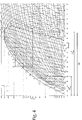
- FIG. 3 shows the closed thermodynamic cycle performed by the heat-pump assembly 11 when cooling fan 20 is switched off.
- the high-pressure and high-temperature refrigerant when coming out of the delivery of refrigerant compressing device 15, the high-pressure and high-temperature refrigerant enters into the condenser 14, i.e. into the air/refrigerant heat exchanger 14, wherein it gives off heat to the airflow f entering into revolving drum 3. Afterwards the high-pressure and high-temperature refrigerant enters into the auxiliary air/refrigerant heat exchanger 19, but, being the cooling fan 20 switched-off, the air/refrigerant heat exchanger 19 has substantially no cooling effects on the refrigerant flowing from the refrigerant-outlet of condenser 14 to the refrigerant expansion valve 16.
- the high-pressure and high-temperature refrigerant flows inside the refrigerant/refrigerant heat exchanger 18 with substantially no pressure drop, wherein it gives off heat to the low-pressure and low-temperature refrigerant flowing towards the suction of refrigerant compressing device 15, thus moving from point c (high-pressure refrigerant inlet of heat exchanger 18) to point d of the Pressure-Enthalpy chart (high-pressure refrigerant outlet of heat exchanger 18 and inlet of refrigerant expansion valve 16) again along a constant-pressure line.
- the refrigerant When coming out of air/refrigerant heat exchanger 19 or out of refrigerant/refrigerant heat exchanger 18, the refrigerant is completely in liquid state and therefore it is located on the left side of the refrigerant Saturated Liquid Curve F' on the Pressure-Enthalpy chart.
- the high-pressure and high-temperature refrigerant flows through the refrigerant expansion valve 16 which subjects the refrigerant to a substantially adiabatic rapid expansion, so as to cause a rapid drop of both refrigerant pressure and refrigerant temperature, and also the evaporation of part of the refrigerant.
- the refrigerant moves from point d (high-pressure refrigerant outlet of heat exchanger 18 and inlet of refrigerant expansion valve 16) to point e of the Pressure-Enthalpy chart (outlet of refrigerant expansion valve 16 and refrigerant-inlet of evaporator 13) along a substantially constant-Enthalpy line that crosses the refrigerant Saturated Liquid Curve F'.
- the low-pressure and low-temperature refrigerant flows inside the evaporator 13, i.e. the air/refrigerant heat exchanger 13, wherein it absorbs heat from the airflow f coming out of revolving drum 3 with substantially no pressure drop.
- the low-pressure and low-temperature refrigerant is allowed to absorb, from the airflow f arriving from revolving drum 3, a heat amount which suffices to perform a complete evaporation and a slight superheating of the refrigerant directed towards the suction of refrigerant compressing device 15.
- a refrigerant In thermodynamic, a refrigerant is defined as being in a superheated condition when the temperature of the refrigerant is greater than the refrigerant saturation temperature at the current refrigerant pressure. This implies that a refrigerant in superheated condition is a refrigerant completely in gaseous state and it is located on the right side of the refrigerant Saturated Vapor Curve F" on the Pressure-Enthalpy chart.
- the refrigerant moves from point e (refrigerant-inlet of heat exchanger 13) to point f of the Pressure-Enthalpy chart (low-pressure refrigerant-inlet of refrigerant/ refrigerant heat exchanger 18) along a substantially constant-Pressure line, and point f of the Pressure-Enthalpy chart (low-pressure refrigerant-inlet of internal refrigerant/refrigerant heat exchanger 18) is located on the right side of the refrigerant Saturated Vapor Curve F".
- the gaseous-state low-pressure and low-temperature refrigerant flows again inside the refrigerant/refrigerant heat exchanger 18 with substantially no pressure drops, wherein it absorbers heat from the high-pressure and high-temperature refrigerant flowing towards the inlet of refrigerant expansion vale 16, thus continuing its superheating process.
- the gaseous-state refrigerant moves from point f (low-pressure refrigerant-inlet of internal refrigerant/refrigerant heat exchanger 18) to point g of the Pressure-Enthalpy chart (suction of the refrigerant compressing device 15) again along a constant-Pressure line.
- the gaseous-state, low-pressure and low-temperature refrigerant enters in the refrigerant compressing device 15 wherein it is compressed so as to close the thermodynamic cycle, and moves from point g (suction of the refrigerant compressing device 15) back to point a the Pressure-Enthalpy chart (delivery of refrigerant compressing device 15) along an inclined Pressure-, and Enthalpy- increasing line.
- Figure 4 instead shows the closed thermodynamic cycle performed by the heat-pump assembly 11 when cooling fan 20 is switched on, i.e. when the refrigerant cooling device 17 cools down the refrigerant flowing from the condenser 14 to the refrigerant expansion device 16.
- the high-pressure and high-temperature refrigerant enters into the auxiliary air/refrigerant heat exchanger 19, wherein, being the cooling fan 20 switched on, the refrigerant is cooled by a stream w of cooling air arriving from the outside of casing 2.
- the refrigerant therefore, moves from point b (refrigerant inlet of heat exchanger 19) to point c of the Pressure-Enthalpy chart (high-pressure refrigerant inlet of heat exchanger 18) along the same constant-pressure line.
- the high-pressure and high-temperature refrigerant flows inside the refrigerant/refrigerant heat exchanger 18 with substantially no pressure drop, wherein it gives off heat to the low-pressure and low-temperature refrigerant flowing towards the suction of refrigerant compressing device 15, thus moving from point c (high-pressure refrigerant inlet of heat exchanger 18) to point d of the Pressure-Enthalpy chart (high-pressure refrigerant outlet of heat exchanger 18 and inlet of refrigerant expansion valve 16) again along a constant-pressure line.
- the liquid-state, high-pressure and high-temperature refrigerant flows through the refrigerant expansion valve 16 which subjects the refrigerant to a substantially adiabatic rapid expansion, so as to cause a rapid drop of both refrigerant pressure and refrigerant temperature, and also the evaporation of part of the refrigerant.
- the refrigerant therefore, moves from point d (high-pressure refrigerant outlet of heat exchanger 18 and inlet of refrigerant expansion valve 16) to point e of the Pressure-Enthalpy chart (outlet of refrigerant expansion valve 16 and refrigerant-inlet of evaporator 13) along a substantially constant-Enthalpy line that crosses the refrigerant Saturated Liquid Curve F'.
- the low-pressure and low-temperature refrigerant flows inside the evaporator 13, i.e. the air/refrigerant heat exchanger 13, wherein it absorbs heat from the airflow f coming out of revolving drum 3 with substantially no pressure drop.
- the low-pressure and low-temperature refrigerant flowing along the evaporator 13 is able to absorb, from the airflow f arriving from revolving drum 3, an increased heat amount which is however insufficient to perform a complete evaporation of the refrigerant directed towards the suction of refrigerant compressing device 15.
- the low-pressure and low-temperature is still partly in liquid state, and it is located on the left side of the refrigerant Saturated Vapor Curve F" on the Pressure-Enthalpy chart.
- the refrigerant moves from point e (refrigerant-inlet of heat exchanger 13) to point f of the Pressure-Enthalpy chart (low-pressure refrigerant-inlet of internal refrigerant/ refrigerant heat exchanger 18) along a substantially constant-Pressure line, but point f is located on the left side of the refrigerant Saturated Vapor Curve F" on the Pressure-Enthalpy chart.
- the liquid-gaseous double-phase, low-pressure and low-temperature refrigerant flows again inside the internal refrigerant/ refrigerant heat exchanger 18 with substantially no pressure drop, wherein it absorbers, from the high-pressure and high-temperature refrigerant flowing towards the inlet of refrigerant expansion vale 16, a heat amount which suffices to complete evaporation of the refrigerant and afterwards to perform the superheating of the refrigerant directed towards the suction of refrigerant compressing device 15.
- the refrigerant while flowing inside the heat exchanger 18, the refrigerant therefore moves from point f (low-pressure refrigerant-inlet of internal heat exchanger 18) to point g of the Pressure-Enthalpy chart (suction of the refrigerant compressing device 15) along a constant-Pressure line that, in this case, crosses the refrigerant Saturated Vapor Curve F" on the Pressure-Enthalpy chart.
- the gaseous-state, low-pressure and low-temperature refrigerant enters in the refrigerant compressing device 15, wherein it is compressed so as to close the thermodynamic cycle, and moves from point g (suction of refrigerant compressing device 15) back to point a the Pressure-Enthalpy chart (delivery of refrigerant compressing device 15) along an inclined Pressure-, and Enthalpy-increasing line.
- the central control unit 7 of laundry dryer 1 is structured/ programmed to drive the refrigerant cooling device 17, i.e. to switch the cooling fan 20 on and off, so as to force the heat-pump assembly 11 to selectively and alternatively perform either the Figure 3 closed thermodynamic cycle which produces, at refrigerant-outlet of evaporator 13, a refrigerant having a relatively high "thermodynamic quality ratio” (i.e. a "thermodynamic quality ratio” preferably, though not necessarily, greater than 1,2); or the Figure 4 closed thermodynamic cycle which produces, at refrigerant-outlet of evaporator 13, a refrigerant having a relatively low "thermodynamic quality ratio” (i.e. a "thermodynamic quality ratio” preferably, though not necessarily, lower than 1 or even lower than 0,7).
- a relatively high "thermodynamic quality ratio” i.e. a "thermodynamic quality ratio” preferably, though not necessarily, greater than 1,2
- the Figure 4 closed thermodynamic cycle which produces, at refriger
- thermodynamic cycle The switching between the Figure 3 thermodynamic cycle and the Figure 4 thermodynamic cycle is purposely controlled so that the low-pressure refrigerant has, at refrigerant-outlet of evaporator 13 (i.e. at refrigerant-outlet of air/refrigerant heat exchanger 13), an average "thermodynamic quality ratio" TQ which is comprised between 0,7 and 1,2.
- the switching between the Figure 3 thermodynamic cycle and the Figure 4 thermodynamic cycle could be purposely controlled so that the low-pressure refrigerant has, at refrigerant-outlet of evaporator 13, an average "thermodynamic quality ratio" TQ which is comprised between 1 and 1,2.
- central control unit 7 purposely controls the activation and/or the revolving speed of cooling fan 20, so as to maintain, preferably when the hot-air generator 5 is in the steady-state working phase, the average "thermodynamic quality ratio" TQ of the low-pressure refrigerant coming out of evaporator 13 within a predetermined operative range encompassed between 0,7 and 1,2, or alternatively between 1 and 1,2.
- central control unit 7 is structured/programmed to switch the cooling fan 20 on and off, or to vary the revolving speed of cooling fan 20, so as to maintain the average "thermodynamic quality ratio" TQ of the low-pressure refrigerant coming out of evaporator 13 within a predetermined operative range which is preferably, though not necessarily, encompassed between 0,7 and 1,15; or is preferably, though not necessarily, encompassed between 0,7 and 1,07; or is even preferably, though not necessarily, encompassed between 0,7 and 1,03.
- the predetermined operative range for the average "thermodynamic quality ratio" TQ could be encompassed between 1 and 1,15, or between 1 and 1,07, or even between 1 and 1,03.
- the central control unit 7 of laundry dryer 1 preferably, though not necessarily, implements a control strategy which tries to maintain, when hot-air generator 5 is preferably in the steady-state working phase, the temperature of the refrigerant at refrigerant-outlet of evaporator 13 very close to the corresponding refrigerant saturation temperature, so that the average "thermodynamic quality ratio" TQ of the low-pressure refrigerant coming out of evaporator 13 varies around 1, i.e. is encompassed between 0,7 and 1,2.
- the refrigerant saturation temperature is the refrigerant temperature at which, for a given pressure of the refrigerant, the liquid-to-gaseous phase-change of the refrigerant is completed. Therefore, if the temperature of the refrigerant at refrigerant-outlet of evaporator 13 is very close to the corresponding refrigerant saturation temperature (either on the right side or on the left side of the refrigerant Saturated Vapour Curve F"), it implies that the Enthalpy H of the refrigerant at refrigerant-outlet of evaporator 13 (i.e.
- the Enthalpy H of the refrigerant at Point f on the Pressure-Enthalpy chart is approximately equal to the Enthalpy H sat V of the refrigerant when in Saturated Vapor Condition at current pressure of the refrigerant.
- the "thermodynamic quality ratio" TQ of the refrigerant at refrigerant-outlet of evaporator 13 is very close to 1, and therefore is encompassed between 0,7 and 1,2.
- central control unit 7 of laundry dryer 1 maintains, when hot-air generator 5 is in the steady-state working phase, the "thermodynamic quality ratio" TQ of the refrigerant at refrigerant-outlet of evaporator 13 between 0,7 and 1,2, via a selected activation and deactivation of cooling fan 20 on the basis of the refrigerant temperature and refrigerant pressure measured at refrigerant-outlet of the evaporator 13, i.e. of the air/refrigerant heat exchanger 13.
- central control unit 7 of laundry dryer 1 firstly measures the current pressure and temperature of the refrigerant at refrigerant-outlet of heat exchanger 13; then calculates the exact refrigerant saturation temperature on the basis of the measured current refrigerant pressure; and finally compares the measured refrigerant temperature with the calculated refrigerant saturation temperature so as to determine whether the calculated refrigerant saturation temperature is greater than the measured refrigerant temperature.
- central control unit 7 of laundry dryer 1 is structured/programmed to switch on and off the cooling fan 20, so as to maintain the average temperature of the refrigerant at refrigerant-outlet of the evaporator 13, i.e. of the air/refrigerant heat exchanger 13, within a given narrow temperature range encompassing/including the calculated refrigerant saturation temperature.
- the upper and lower ends of this narrow temperature range are conveniently selected so that the average "thermodynamic quality ratio" TQ of the low-pressure refrigerant coming out of evaporator 13 is encompassed between 0,7 and 1,2.
- central control unit 7 is structured/programmed to switch the cooling fan 20 on and off, or to vary the revolving speed of cooling fan 20, so as to maintain the average "thermodynamic quality ratio" TQ of the low-pressure refrigerant coming out of evaporator 13 within a predetermined operative range which is preferably, though not necessarily, encompassed between 0,7 and 1,15; or is preferably, though not necessarily, encompassed between 0,7 and 1,07; or is even preferably, though not necessarily, encompassed between 0,7 and 1,03.
- the temperature of the refrigerant at refrigerant-outlet of evaporator 13 is preferably, though not necessarily, maintained from 3°C below the calculated refrigerant saturation temperature to 6°C above the calculated refrigerant saturation temperature.
- the difference between the measured refrigerant temperature at refrigerant-outlet of heat exchanger 13 and the calculated refrigerant saturation temperature is preferably, though not necessarily, maintained within an acceptable temperature range spanning between - 3°C and +6°C.
- central control unit 7 of laundry dryer 1 is preferably, though not necessarily, structured/programmed
- thermodynamic quality ratio TQ of the refrigerant at refrigerant-outlet of evaporator 13, i.e. of heat exchanger 13 is preferably performed when hot-air generator 5 is in the steady-state working phase.
- cooling fan 20 reduces the "thermodynamic quality ratio" TQ of the refrigerant at refrigerant-outlet of evaporator 13 and that deactivation of cooling fan 20 increases the "thermodynamic quality ratio" TQ of the refrigerant at refrigerant-outlet of evaporator 13
- central control unit 7 of laundry dyer 1 deactivates the cooling fan 20 for increasing the "thermodynamic quality ratio" TQ of the refrigerant at refrigerant-outlet of evaporator 13, whenever the refrigerant temperature at refrigerant-outlet of the evaporator 13 goes below a predetermined first threshold value; and activates the cooling fan 20 for reducing the "thermodynamic quality ratio" TQ of the refrigerant at refrigerant-outlet of the evaporator 13, whenever the refrigerant temperature at refrigerant-outlet of heat evaporator 13 rises above a predetermined second threshold value which is higher than said first threshold value.
- the first threshold value is 3°C below the calculated refrigerant saturation temperature
- the second threshold value is 6°C above the calculated refrigerant saturation temperature
- the first and the second threshold value are conveniently selected to assure that the average "thermodynamic quality ratio" TQ of the refrigerant coming out of heat exchanger 13 remains encompassed between 0,7 and 1,2; or preferably between 0,7 and 1,15; or preferably between 0,7 and 1,07; or preferably between 0,7 and 1,03.
- the first and the second threshold value could be conveniently selected so as to maintain the average "thermodynamic quality ratio" TQ encompassed between 1 and 1,15, or between 1 and 1,07, or even between 1 and 1,03.
- central control unit 7 deactivates the cooling fan 20 for increasing the current "thermodynamic quality ratio" TQ of the refrigerant at refrigerant-outlet of the evaporator 13, whenever the refrigerant temperature at refrigerant-outlet of evaporator 13 goes too far below the corresponding calculated refrigerant saturation temperature; and activates the cooling fan 20 for reducing the current "thermodynamic quality ratio" TQ of the refrigerant at refrigerant-outlet of the evaporator 13, whenever the refrigerant temperature at refrigerant-outlet of evaporator 13 goes too far above the corresponding refrigerant saturation temperature.
- central control unit 7 of laundry dryer 1 activates the cooling fan 20 to maximize the cooling of the refrigerant flowing through heat exchanger 19 for reducing the "thermodynamic quality ratio" TQ of the refrigerant at refrigerant-outlet of the evaporator 13.
- This intensive cooling down of the refrigerant is however performed only if the hot-air generator 5 is in the steady-state working phase.
- variable-speed cooling fan 20 allows a much more accurate control of the "thermodynamic quality ratio" TQ of the refrigerant at refrigerant-outlet of evaporator 13, i.e. at refrigerant-outlet of air/refrigerant heat exchanger 13.
- the laundry dryer 1 is provided with at least one pressure sensor (not shown) and with at least one temperature sensor (not shown), both located at refrigerant-outlet of evaporator 13 (i.e. at refrigerant-outlet of the air/ refrigerant heat exchanger 13), for continuously measuring the refrigerant local pressure and temperature.
- refrigerant pressure at outlet of evaporator 13 is substantially equal to the refrigerant pressure at suction of refrigerant compressing device 15 or at low-pressure refrigerant outlet of internal heat exchanger 18, the pressure sensor could also be located at low-pressure refrigerant outlet of internal heat exchanger 18 or at suction of refrigerant compressing device 15.
- central control unit 7 of laundry dryer 1 can maintain between 0,7 and 1,2 the "thermodynamic quality ratio" TQ of the refrigerant at refrigerant-outlet of evaporator 13, via a selected activation and deactivation of cooling fan 20 on the basis of the current pressure and temperature of the refrigerant measured at low-pressure refrigerant outlet of refrigerant/refrigerant heat exchanger 18.
- the measurement of the current pressure of the refrigerant at low-pressure refrigerant outlet of internal heat exchanger 18 may be replaced by the measurement of the current pressure of the refrigerant at refrigerant-outlet of evaporator 13 because substantially no pressure drops occurs while the refrigerant flows along the low pressure side of internal heat exchanger 18, or by the measurement of the current pressure of the refrigerant at suction of refrigerant compressing device 15.
- the refrigerant saturation temperature is a scalar physical quantity which depends strictly on the type of refrigerant and on its pressure, therefore central control unit 7 firstly measures the current pressure of the refrigerant at low-pressure refrigerant outlet of internal heat exchanger 18, or at suction of refrigerant compressing device 15, or at refrigerant-outlet of heat exchanger 13; then calculates the exact refrigerant saturation temperature on the basis of the measured current refrigerant pressure; and finally compares the refrigerant temperature measured at low-pressure refrigerant outlet of heat exchanger 18 with the calculated refrigerant saturation temperature, so as to determine whether the refrigerant coming out of the low-pressure refrigerant outlet of internal heat exchanger 18 is superheated and the current amount of such superheating.
- the difference between the refrigerant temperature measured at low-pressure refrigerant outlet of heat exchanger 18 and the calculated refrigerant saturation temperature is very high (for example greater than 18°C), it means that the low-pressure refrigerant is deeply superheated and that, therefore, the low-pressure refrigerant comes out of evaporator 13 when refrigerant evaporation is already finalized.
- the refrigerant temperature at refrigerant-outlet of evaporator 13 has to be greater than the corresponding refrigerant saturation temperature, and the "thermodynamic quality ratio" TQ of the refrigerant at refrigerant-outlet of evaporator 13 has to be greater than 1.
- the difference between the refrigerant temperature measured at low-pressure refrigerant outlet of heat exchanger 18 and the calculated refrigerant saturation temperature is very low (for example lower than 3°C), it means that the low-pressure refrigerant is only slightly superheated and that, therefore, the low-pressure refrigerant comes out of the evaporator 13 still partly in liquid state.
- the refrigerant temperature at refrigerant-outlet of evaporator 13 has to be lower than the corresponding refrigerant saturation temperature, and the "thermodynamic quality ratio" TQ of the refrigerant at refrigerant-outlet of evaporator 13 has to be lower than 1.
- central control unit 7 of laundry dryer 1 is structured/programmed to switch the cooling fan 20 on and off, so as to keep the difference between the current temperature of the refrigerant at low-pressure refrigerant outlet of internal heat exchanger 18 and the calculated refrigerant saturation temperature, i.e. the current refrigerant superheating, within a predetermined temperature range which is located above the calculated refrigerant saturation temperature and which depends on the structure of internal heat exchanger 18.
- thermodynamic quality ratio TQ of the low-pressure refrigerant coming out of evaporator 13 is encompassed between 0,7 and 1,2.
- central control unit 7 is preferably, structured/programmed to switch the cooling fan 20 on and off, or to vary the revolving speed of cooling fan 20, so as to maintain the average "thermodynamic quality ratio" TQ of the low-pressure refrigerant coming out of evaporator 13 within a predetermined operative range which is preferably, though not necessarily, encompassed between 0,7 and 1,15; or is preferably, though not necessarily, encompassed between 0,7 and 1,07; or is even preferably, though not necessarily, encompassed between 0,7 and 1,03.
- the operative range for the average "thermodynamic quality ratio" TQ could be encompassed between 1 and 1,15, or between 1 and 1,07, or even between 1 and 1,03.
- the central control unit 7 of laundry dryer 1 is preferably, though not necessarily, structured/programmed to switch the cooling fan 20 on and off, so to maintain the average temperature the refrigerant at low-pressure refrigerant outlet of internal heat exchanger 18 from 3°C to 20°C above the calculated refrigerant saturation temperature.
- the difference between the current temperature of the refrigerant at low-pressure refrigerant outlet of internal heat exchanger 18 and the corresponding calculated refrigerant saturation temperature is preferably, though not necessarily, maintained within an acceptable temperature range spanning between 3°C and 20°C.
- central control unit 7 of laundry dryer 1 is preferably, though not necessarily, structured/programmed
- the central control unit 7 of laundry dyer 1 deactivates the cooling fan 20 for increasing the current "thermodynamic quality ratio" TQ of the refrigerant at refrigerant-outlet of evaporator 13, whenever the refrigerant temperature at low-pressure refrigerant outlet of internal heat exchanger 18 goes below a predetermined first threshold value; and activates the cooling fan 20 for reducing the current "thermodynamic quality ratio" TQ of the refrigerant at refrigerant-outlet of evaporator 13, whenever the refrigerant temperature at low-pressure refrigerant outlet of refrigerant/refrigerant heat exchanger 18 exceeds a predetermined second threshold value which is greater than said first threshold value.
- cooling fan 20 reduces the "thermodynamic quality ratio" TQ of the refrigerant at refrigerant-outlet of heat exchanger 13; whereas deactivation of cooling fan 20 increases the "thermodynamic quality ratio" TQ of the refrigerant at refrigerant-outlet of heat exchanger 13.
- the first threshold value is 3°C above the calculated refrigerant saturation temperature
- the second threshold value is 20°C above the calculated refrigerant saturation temperature
- the first and the second threshold value are conveniently selected to assure that the average "thermodynamic quality ratio" TQ of the refrigerant coming out of evaporator 13 remains encompassed between 0,7 and 1,2; or preferably between 0,7 and 1,15; or preferably between 0,7 and 1,07; or preferably between 0,7 and 1,03.
- the first and the second threshold value could be conveniently selected so as to maintain the average "thermodynamic quality ratio" TQ encompassed between 1 and 1,15, or between 1 and 1,07, or even between 1 and 1,03.
- central control unit 7 keeps the cooling fan 20 switched off for increasing the current "thermodynamic quality ratio" TQ of the refrigerant at refrigerant-outlet of evaporator 13, if the refrigerant temperature at low-pressure refrigerant outlet of internal heat exchanger 18 decreases/arrives too close to the corresponding refrigerant saturation temperature; and keeps the cooling fan 20 switched on for reducing the current "thermodynamic quality ratio" TQ of the refrigerant at refrigerant-outlet of evaporator 13, if the refrigerant temperature at low-pressure refrigerant outlet of internal heat exchanger 18 goes too much high with respect to the corresponding calculated refrigerant saturation temperature.
- variable-speed cooling fan 20 allows a much more accurate control of the "thermodynamic quality ratio" TQ of the refrigerant at refrigerant-outlet of heat exchanger 13, i.e. of evaporator 13.
- the laundry dryer 1 is provided with at least one pressure sensor (not shown) and with at least one temperature sensor (not shown), both located at low-pressure refrigerant outlet of internal heat exchanger 18 for continuously measuring the refrigerant local pressure and temperature.
- refrigerant pressure at low-pressure refrigerant outlet of internal heat exchanger 18 is substantially equal to the refrigerant pressure at suction of refrigerant compressing device 15 or at outlet of evaporator 13, the pressure sensor could also be located at outlet of evaporator 13 or at suction of refrigerant compressing device 15.
- thermodynamic quality ratio TQ of the refrigerant at refrigerant-outlet of evaporator 13 is lower than 1 when the refrigerant temperature at refrigerant-outlet of evaporator 13 goes below the refrigerant saturation temperature at the same refrigerant pressure, and it is greater than 1 when the refrigerant temperature at refrigerant-outlet of evaporator 13 rises above the refrigerant saturation temperature at the same refrigerant pressure.
- the refrigerant coming out of the refrigerant-outlet of evaporator 13 is at least partially in liquid state, and has been subjected to a "negative" superheating while flowing through the evaporator 13.
- the refrigerant coming out of the refrigerant-outlet of evaporator 13 is completely vaporized, i.e. in gaseous state, and has been subjected to a "positive" superheating while flowing through the evaporator 13.
- central control unit 7 can check whether the current "thermodynamic quality ratio" TQ of the refrigerant at refrigerant-outlet of evaporator 13 goes below 1 or above 1, via a direct measurement and comparison between the temperature drop of the refrigerant flowing in the high-pressure side of internal heat exchanger 18, and the temperature rise of the refrigerant flowing in the low-pressure side of the same internal heat exchanger 18.
- the refrigerant flowing in the low-pressure side of heat exchanger 18 is merely superheated, and the increase of the refrigerant temperature measured at the low-pressure side of heat exchanger 18 is significantly higher than the drop of refrigerant temperature measured at the high-pressure side of heat exchanger 18.
- a refrigerant almost completely in liquid state i.e. the refrigerant flowing in the high-pressure side of heat exchanger 18
- has a thermal capacity, i.e. a specific heat considerably higher than that of a whole gaseous-state refrigerant (i.e. the refrigerant flowing in the low-pressure side of heat exchanger 18).
- the refrigerant flowing in the low-pressure side of heat exchanger 18 has to be firstly completely vaporized and then superheated, thus the difference between the increase of the refrigerant temperature measured at the low-pressure side of heat exchanger 18 and the drop of the refrigerant temperature measured at the high-pressure side of heat exchanger 18 is small. This is due to the fact that the average thermal capacity of the refrigerant flowing in the low-pressure side of heat exchanger 18 becomes close to the thermal capacity of the liquid-state refrigerant flowing in the high-pressure side of heat exchanger 18.
- central control unit 7 of laundry dryer 1 may be structured/programmed
- central control unit 7 of laundry dryer 1 may be structured/programmed
- the first tolerance value is significantly greater than 0°C (for example 25°C), whereas the second tolerance value is preferably, though not necessarily, lower than the first tolerance value.
- central control unit 7 of laundry dryer 1 activates the cooling fan 20 for reducing the current "thermodynamic quality ratio" TQ of the refrigerant at refrigerant-outlet of evaporator 13, if the temperature rise of the refrigerant flowing in the low-pressure side of heat exchanger 18 exceeds of a predetermined first tolerance value the temperature drop of the refrigerant flowing in the high-pressure side of heat exchanger 18 (for example the temperature rise of the low-pressure refrigerant is more than 25°C higher than the temperature drop of the high-pressure refrigerant).
- central control unit 7 of laundry dryer 1 deactivates the cooling fan 20 for increasing the current "thermodynamic quality ratio" TQ of the refrigerant at refrigerant-outlet of evaporator 13, if the temperature drop of the refrigerant flowing in the high-pressure side of heat exchanger 18 exceeds of a predetermined second tolerance value the temperature rise of the refrigerant flowing in the low-pressure side of heat exchanger 18 (for example the temperature drop of the high-pressure refrigerant is more than 3°C higher than the temperature rise of the low-pressure refrigerant); or if the temperature rise of the refrigerant flowing in the low-pressure side of heat exchanger 18 goes below a predetermined third threshold value (for example it goes below 5°C).
- central control unit 7 of laundry dryer 1 is preferably, though not necessarily, structured/programmed to measure the temperature drop of the refrigerant flowing in the high-pressure side of internal heat exchanger 18, and the temperature rise of the refrigerant flowing in the low-pressure side of internal heat exchanger 18; and to drive the refrigerant cooling device 17, i.e.
- the refrigerant thermodynamic-parameters adjusting means so as to keep the difference between the temperature rise of the refrigerant flowing in the low-pressure side of heat exchanger 18 and the temperature drop of the refrigerant flowing in the high-pressure side of heat exchanger 18, within a predetermined tolerance range whose upper and lower ends are conveniently selected so that the "thermodynamic quality ratio" TQ of the refrigerant coming out of evaporator 13 remains encompassed between 0,7 and 1,2.
- this tolerance range are conveniently selected so that the average "thermodynamic quality ratio" TQ of the refrigerant coming out of heat exchanger 13 remains encompassed preferably, though not necessarily, between 0,7 and 1,15, or between 0,7 and 1,07, or even between 0,7 and 1,03.
- the upper and lower ends of this tolerance range could be conveniently selected so as to maintain the average "thermodynamic quality ratio" TQ encompassed between 1 and 1,15, or between 1 and 1,07, or even between 1 and 1,03.
- central control unit 7 is structured/programmed to switch the cooling fan 20 on and off, so as to keep the difference between the temperature rise of the refrigerant flowing in the low-pressure side of heat exchanger 18 and the temperature drop of the refrigerant flowing in the high-pressure side of heat exchanger 18, within a tolerance range preferably, though not necessarily, extending from -3°C to 25°C.
- central control unit 7 of laundry dryer 1 activates the cooling fan 20 for reducing the current "thermodynamic quality ratio" TQ of the refrigerant at refrigerant-outlet of evaporator 13, whenever the difference between the temperature rise of the refrigerant flowing in the low-pressure side of heat exchanger 18 and the temperature drop of the refrigerant flowing in the high-pressure side of heat exchanger 18 exceeds the upper limit of said tolerance range (for example the upper limit is equal to 25°C).
- central control unit 7 deactivates the cooling fan 20 for increasing the "thermodynamic quality ratio" TQ of the refrigerant at refrigerant-outlet of evaporator 13, whenever the difference between the temperature rise of the refrigerant flowing in the low-pressure side of heat exchanger 18 and the temperature drop of the refrigerant flowing in the high-pressure side of heat exchanger 18 goes below the lower limit of said tolerance (for example the lower limit is equal to -3°C); or whenever the temperature rise of the refrigerant flowing in the low-pressure side of heat exchanger 18 goes below a predetermined threshold value (for example it goes below 5°C).
- this threshold value is greater than zero so as to ensure that the low-pressure and low-temperature refrigerant flowing in the low-pressure side of internal heat exchanger 18 is at least a little bit superheated before reaching the suction of refrigerant compressing device 15.
- the laundry dryer 1 is provided with four temperature sensors (not shown), each located at a respective inlet or outlet of heat exchanger 18 to measure the corresponding refrigerant temperatures.
- central control unit 7 maintains, when hot-air generator 5 is in the steady-state working phase, the "thermodynamic quality ratio" TQ of the refrigerant at refrigerant-outlet of evaporator 13 between 0,7 and 1,2, via a selected activation and deactivation of cooling fan 20 on the basis of the temperature difference of the refrigerant flowing in the evaporator 13, i.e. in the air/refrigerant heat exchanger 13.
- central control unit 7 of laundry dryer 1 can measure the temperature drop of the refrigerant flowing in evaporator 13 and, when the hot-air generator is in the steady-state working phase, it can continuously switch the cooling fan 20 on and off so as to keep the temperature drop of the refrigerant flowing through the evaporator 13 as constant as possible within a given narrow temperature range.
- thermodynamic quality ratio TQ of the refrigerant coming out of heat exchanger 13 is encompassed between 0,7 and 1,2.
- the upper and lower ends of this narrow temperature range are conveniently selected so that the average "thermodynamic quality ratio" TQ of the refrigerant coming out of evaporator 13 is preferably, though not necessarily, encompassed between 0,7 and 1,15, or between 0,7 and 1,07, or even between 0,7 and 1,03.
- the average "thermodynamic quality ratio" TQ could be encompassed between 1 and 1,15, or between 1 and 1,07, or even between 1 and 1,03.
- central control unit 7 is structured/programmed to continuously switch the cooling fan 20 on and off, so as to keep either the temperature rise of the refrigerant flowing through the evaporator 13 within a given narrow temperature range extending from approximately 0°C to 15°C, and preferably, though not necessarily, extending from 0°C to 10°C and preferably, though not necessarily, extending from 0°C to 5°C; or the temperature drop of the refrigerant flowing through the evaporator 13 within a given narrow temperature range extending from approximately 0°C to 10°C, and preferably, though not necessarily, extending from 0,2°C to 5°C.
- central control unit 7 is structured/programmed to continuously switch the cooling fan 20 on and off so as to keep the temperature difference of the refrigerant flowing through the evaporator 13 within a given temperature range extending approximately from +15°C to -10°C, or even preferably, though not necessarily, from +10°C to -5°C or +5°C to -5°C.
- central control unit 7 of laundry dryer 1 is preferably, though not necessarily, structured/programmed
- the laundry dryer 1 is provided with two temperature sensors located, respectively, at refrigerant-inlet and at refrigerant-outlet of evaporator 13 to measure the corresponding refrigerant temperatures.
- central control unit 7 may improve precision of the fourth control-strategy referred above via an additional control of the temperature drop of the refrigerant that flows in the high-pressure side of internal heat exchanger 18. If the temperature drop of the refrigerant flowing through the evaporator 13 is slightly greater than 0°C and, at the same time, the temperature drop of the refrigerant flowing in the high-pressure side of refrigerant/refrigerant heat exchanger 18 is significantly high, this means that internal heat exchanger 18 is finalizing the evaporation of the low-pressure refrigerant.
- This combined control-strategy is particularly helpful when the behaviour of the refrigerant flowing in the heat-pump assembly 11 is that of a pure/ideal fluid.
- the central control unit 7 of laundry dryer 1 maintains, when hot-air generator 5 is in the steady-state working phase, the "thermodynamic quality ratio" TQ of the refrigerant at refrigerant-outlet of evaporator 13 between 0,7 and 1,2, via a selected activation and deactivation of cooling fan 20 on the basis of the temperature drop/rise of the refrigerant flowing in the evaporator 13, i.e. flowing in the air/refrigerant heat exchanger 13, and of the temperature drop of the refrigerant flowing through the high-pressure side of internal heat exchanger 18.
- the temperature drop of the refrigerant flowing through the evaporator 13 is very close to zero when the refrigerant coming out from evaporator 13 is partly in liquid state, because the refrigerant liquid-to-gaseous phase-change takes place at a constant temperature and this phase-change is not finalized at refrigerant-outlet of heat exchanger 13.
- the drop of the refrigerant temperature at the high-pressure side of internal heat exchanger 18 is considerably high when the refrigerant coming out from evaporator 13 is partly in liquid state, because the high-temperature and high-pressure refrigerant flowing through internal heat exchanger 18 has to transfer to the low-pressure refrigerant flowing through the same heat exchanger enough heat to finalize both the evaporation and the superheating.
- the latent evaporation heat transfer coefficient of the refrigerant in fact, is considerably higher than the sensible heat transfer coefficient of the same refrigerant.
- the central control unit 7 of laundry dryer 1 is structured/programmed to measure both the temperature drop/rise of the refrigerant flowing in evaporator 13, and the temperature drop of the refrigerant that flows in the high-pressure side of internal heat exchanger 18; and to continuously switch, when the hot-air generator is in the steady-state working phase, the cooling fan 20 on and off
- the first temperature range extends preferably, though not necessarily, from +15°C to -10°C, or preferably, though not necessarily, from +10°C to -5°C; whereas the second temperature range extends preferably, though not necessarily, from 10°C to 25°C, thus assuring that the complete vaporization of the refrigerant and subsequent superheating of the refrigerant take place inside internal heat exchanger 18 or giving an extra superheating to the refrigerant coming from the evaporator 13.
- Central control unit 7 is therefore preferably, though not necessarily, structured/programmed
- central control unit 7 of laundry dryer 1 activates the cooling fan 20 for reducing the "thermodynamic quality ratio" TQ of the refrigerant at refrigerant-outlet of heat exchanger 13, whenever the temperature rise of the refrigerant flowing through the evaporator 13 exceeds a first threshold value (for example 15°C), and whenever, at the same time, the temperature drop of the refrigerant flowing through the high-pressure side of internal heat exchanger 18 goes below a second threshold value (for example 5°C); and deactivates the cooling fan 20 for increasing the "vapor quality" of the refrigerant at refrigerant-outlet of heat exchanger 13, whenever the temperature drop of the refrigerant flowing through the evaporator 13 goes below a third threshold value (for example -10°C) which is lower than said first threshold value, and whenever, at the same time, the temperature drop of the refrigerant flowing through the high-pressure side of internal heat exchanger 18 exceeds a fourth threshold value (
- cooling fan 20 reduces the "thermodynamic quality ratio" TQ of the refrigerant at refrigerant-outlet of the evaporator 13; whereas deactivation of cooling fan 20 increases the "thermodynamic quality ratio" TQ of the refrigerant at refrigerant-outlet of the evaporator 13.
- the laundry dryer 1 is provided with four temperature sensors located, respectively, at refrigerant-inlet of evaporator 13, at refrigerant-outlet of evaporator 13, at high-pressure refrigerant inlet of heat exchanger 18 and finally at high-pressure refrigerant outlet of heat exchanger 18 to measure the corresponding refrigerant temperatures.
- central control unit 7 maintains, when hot-air generator 5 is in the steady-state working phase, the "thermodynamic quality ratio" TQ of the refrigerant at refrigerant-outlet of evaporator 13 between 0,7 and 1,2, via a selected activation and deactivation of cooling fan 20 on the basis of the temperature drop/rise of the refrigerant flowing in the evaporator 13 (i.e. flowing in heat exchanger 13), and of the temperature rise of the refrigerant flowing in the low-pressure side of internal heat exchanger 18.
- this combined control-strategy is particularly helpful when the behaviour of the refrigerant flowing in the heat-pump assembly 11 is that of a pure/ideal fluid.
- the temperature drop of the refrigerant flowing through the evaporator 13 is very close to zero when the refrigerant coming out of evaporator 13 is partly in liquid state, because the refrigerant liquid-to-gaseous phase-change takes place at a constant temperature and it is not finalized at refrigerant-outlet of heat exchanger 13.
- the temperature rise of the refrigerant flowing through the low-pressure side of internal heat exchanger 18 is significantly high, i.e. significantly greater than zero, because the refrigerant flowing in the low-pressure side of internal heat exchanger 18 is to be only superheated.
- central control unit 7 of laundry dryer 1 can measure both the temperature rise/ drop of the refrigerant flowing in the evaporator 13, and the temperature rise of the refrigerant flowing in the low-pressure side of internal heat exchanger 18; and, when hot-air generator is in the steady-state working phase, it can switch the cooling fan 20 on and off (i.e.
- TQ of the refrigerant at refrigerant-outlet of evaporator 13 adjusts the "thermodynamic quality ratio" TQ of the refrigerant at refrigerant-outlet of evaporator 13), so as to keep the temperature rise/drop of the refrigerant flowing through the evaporator 13 as constant as possible within a first narrow temperature range preferably, though not necessarily, extending from +15°C to -10°C, and, at the same time, so as to keep the temperature rise of the refrigerant flowing through the low-pressure side of heat exchanger 18 within a second broader temperature range which is always above than the first temperature range, and which preferably, though not necessarily, extends from 3°C to 25°C.
- central control unit 7 is preferably, though not necessarily, structured/programmed
- central control unit 7 of laundry dryer 1 activates the cooling fan 20 for reducing the "thermodynamic quality ratio" TQ of the refrigerant at refrigerant-outlet of heat exchanger 13, whenever the temperature rise of the refrigerant flowing through the evaporator 13 exceeds a first threshold value (for example 15°C), and whenever the temperature rise of the refrigerant flowing through the low-pressure side of internal heat exchanger 18 exceeds a second threshold value (for example 25°C); and deactivates the cooling fan 20 for increasing the "thermodynamic quality ratio" TQ of the refrigerant at refrigerant-outlet of heat exchanger 13, whenever the temperature drop of the refrigerant flowing through the evaporator 13 goes below a third threshold value (for example -10°C) which is lower than said first threshold value, and the temperature rise of the refrigerant flowing through the low-pressure side of internal heat exchanger 18 goes below a fourth threshold value (for example 3°C) which is
- cooling fan 20 reduces the "thermodynamic quality ratio" TQ of the refrigerant at refrigerant-outlet of heat exchanger 13; whereas deactivation of cooling fan 20 increases the "thermodynamic quality ratio" TQ of the refrigerant at refrigerant-outlet of heat exchanger 13.
- the fourth threshold value is always greater than the second threshold value.
- the heat exchanger 18 only finalizes the superheating of the refrigerant.
- the liquid state portion of the refrigerant coming out from the evaporator 13 is excessive, and the internal heat exchanger 18 is not able to finalize the evaporation of low-pressure refrigerant and afterwards superheat the refrigerant directed towards the suction of refrigerant compressing device 15.
- the laundry dryer 1 is provided with three temperature sensors located, respectively, at refrigerant-inlet of the evaporator 13, at refrigerant-outlet of the evaporator 13, and finally at low-pressure refrigerant outlet of heat exchanger 18 to measure the corresponding refrigerant temperatures.
- the refrigerant temperature at low-pressure refrigerant inlet of heat exchanger 18, in fact, is to be considered equal to the refrigerant temperature at refrigerant-outlet of heat exchanger 13.
- control-strategy can be also adapted to deal with refrigerant zeotropic blends, taking into consideration that the complete liquid-to-gaseous phase-change of a refrigerant zeotropic blend takes place at increasing temperature. This implies that the refrigerant flowing through the evaporator 13 is subjected to a temperature rise greater than zero, even if the liquid-to-gaseous phase-change is not finalized at refrigerant-outlet of evaporator 13.
- central control unit 7 of laundry dryer 1 can measure the temperature rise of the refrigerant flowing in evaporator 13 and, when the hot-air generator is in the steady-state working phase, it can continuously switch the cooling fan 20 on and off so as to keep the temperature rise of the refrigerant flowing through the evaporator 13 as constant as possible within a given narrow temperature range.
- the upper and lower ends of this narrow temperature range are conveniently selected so that the average "thermodynamic quality ratio" TQ of the refrigerant coming out of evaporator 13 is encompassed between 0,7 and 1,2, and in particular it is preferably, though not necessarily, encompassed between 0,7 and 1,15, or between 0,7 and 1,07, or even between 0,7 and 1,03.
- the upper and lower ends of this narrow temperature range could be conveniently selected so as to maintain the average "thermodynamic quality ratio" TQ encompassed between 1 and 1,15, or between 1 and 1,07, or even between 1 and 1,03.
- central control unit 7 is structured/programmed to continuously switch the cooling fan 20 on and off, so as to keep the temperature rise of the refrigerant flowing through the evaporator 13 within a given narrow temperature range extending from approximately 1°C to 20°C, or even from 0°C to 15°C, and preferably, though not necessarily, extending from 2°C to 7°C.
- central control unit 7 of laundry dryer 1 is preferably, though not necessarily, structured/programmed
- central control unit 7 of laundry dryer 1 activates, when hot-air generator 5 is in the steady-state working phase, the cooling fan 20 for reducing the "thermodynamic quality ratio" TQ of the refrigerant at refrigerant-outlet of heat exchanger 13, whenever the temperature rise of the refrigerant flowing through the evaporator 13 exceeds a first threshold value (for example 7°C).
- a first threshold value for example 7°C
- central control unit 7 deactivates the cooling fan 20 for increasing the "thermodynamic quality ratio" TQ of the refrigerant at refrigerant-outlet of evaporator 13, whenever the temperature rise of the refrigerant flowing through the evaporator 13 goes below a second threshold value (for example 2°C) which is lower than said upper threshold value.
- a second threshold value for example 2°C
- the laundry dryer 1 is again provided with two temperature sensors located, respectively, at refrigerant-inlet and at refrigerant-outlet of evaporator 13 to measure the corresponding refrigerant temperatures.
- central control unit 7 may optionally improve precision of this last control-strategy, via an additional control of the temperature drop of the refrigerant that flows in the high-pressure side of internal heat exchanger 18. If the temperature rise of the refrigerant flowing through the evaporator 13 is slightly greater than 0°C and, at the same time, the temperature drop of the refrigerant flowing in the high-pressure side of refrigerant/refrigerant heat exchanger 18 is significantly high, this means that internal heat exchanger 18 is finalizing the evaporation of the low-pressure refrigerant and that, therefore, the refrigerant coming out of evaporator 13 is partly in liquid state.
- the central control unit 7 of laundry dryer 1 maintains, when hot-air generator 5 is in the steady-state working phase, the "thermodynamic quality ratio" TQ of the refrigerant at refrigerant-outlet of evaporator 13 between 0,7 and 1,2, via a selected activation and deactivation of cooling fan 20 on the basis of the temperature rise of the refrigerant flowing through evaporator 13 (i.e. flowing through the air/refrigerant heat exchanger 13), and of the temperature drop of the refrigerant flowing through the high-pressure side of internal heat exchanger 18.
- the temperature rise of the refrigerant flowing through the evaporator 13 is slightly greater than zero when the refrigerant coming out of evaporator 13 is partly in liquid state.
- the drop of the refrigerant temperature at the high-pressure side of internal heat exchanger 18 is considerably high when the refrigerant coming out of evaporator 13 is partly in liquid state, because the high-temperature and high-pressure refrigerant flowing through the internal heat exchanger 18 has to transfer to the low-pressure refrigerant flowing through the same heat exchanger enough heat to finalize both the evaporation and the superheating.
- the latent evaporation heat transfer coefficient of the refrigerant in fact, is considerably higher than the sensible heat transfer coefficient of the same refrigerant.
- central control unit 7 of laundry dryer 1 can measure both the temperature rise of the refrigerant flowing in evaporator 13, and the temperature drop of the refrigerant that flows in the high-pressure side of internal heat exchanger 18; and, when the hot-air generator is in the steady-state working phase, it can continuously switch on and off the cooling fan 20, so as to keep the temperature rise of the refrigerant flowing through the evaporator 13 as constant as possible within a first narrow temperature range which extends preferably, though not necessarily, from 2°C and 7°C, and, at the same time, so as to keep the temperature drop of the refrigerant flowing through the high-pressure side of internal heat exchanger 18 within a second temperature range whose upper and lower ends are both significantly higher than 0°C.
- the first temperature range extends preferably, though not necessarily, from 2°C to 8°C; whereas the second temperature range extends preferably, though not necessarily, from 10°C to 20°C, thus assuring that the complete vaporization of the refrigerant and subsequent superheating of the refrigerant take place inside internal heat exchanger 18.
- Central control unit 7 is therefore preferably, though not necessarily, structured/programmed
- central control unit 7 of laundry dryer 1 activates the cooling fan 20 for reducing the "thermodynamic quality ratio" TQ of the refrigerant at refrigerant-outlet of heat exchanger 13, whenever the temperature rise of the refrigerant flowing through the evaporator 13 exceeds a first threshold value (for example 8°C), and whenever, at the same time, the temperature drop of the refrigerant flowing through the high-pressure side of internal heat exchanger 18 goes below a second threshold value (for example 10°C); and deactivates the cooling fan 20 for increasing the "thermodynamic quality ratio" TQ of the refrigerant at refrigerant-outlet of heat exchanger 13, whenever the temperature rise of the refrigerant flowing through the evaporator 13 goes below a third threshold value (for example 2°C) which is lower than said first threshold value, and whenever, at the same time, the temperature drop of the refrigerant flowing through the high-pressure side of internal heat exchanger 18 exceeds a first threshold value (for example 8°C), and whenever, at the same time,
- cooling fan 20 reduces the "thermodynamic quality ratio" TQ of the refrigerant at refrigerant-outlet of the evaporator 13; whereas deactivation of cooling fan 20 increases the "thermodynamic quality ratio" TQ of the refrigerant at refrigerant-outlet of the evaporator 13.
- the laundry dryer 1 is again provided with four temperature sensors located, respectively, at refrigerant-inlet of evaporator 13, at refrigerant-outlet of evaporator 13, at high-pressure refrigerant inlet of heat exchanger 18, and finally at high-pressure refrigerant outlet of heat exchanger 18, to measure the corresponding refrigerant temperatures.
- central control unit 7 maintains, when hot-air generator 5 is in the steady-state working phase, the "thermodynamic quality ratio" TQ of the refrigerant at refrigerant-outlet of evaporator 13 between 0,7 and 1,2, via a selected activation and deactivation of cooling fan 20 on the basis of the temperature rise of the refrigerant flowing through the evaporator 13, i.e. flowing through heat exchanger 13, and of the temperature rise of the refrigerant flowing through the low-pressure side of internal heat exchanger 18.
- the temperature rise of the refrigerant flowing through the evaporator 13 is slightly higher than zero when the refrigerant coming out of evaporator 13 is partly in liquid state.
- the temperature rise of the refrigerant flowing through the low-pressure side of internal heat exchanger 18 is significantly high, i.e. significantly greater than zero, because the refrigerant flowing in the low-pressure side of internal heat exchanger 18 is to be only superheated.
- central control unit 7 of laundry dryer 1 can measure both the temperature rise of the refrigerant flowing in the evaporator 13, and the temperature rise of the refrigerant flowing in the low-pressure side of internal heat exchanger 18; and, when hot-air generator is in the steady-state working phase, it can switch the cooling fan 20 on and off (i.e.
- TQ of the refrigerant at refrigerant-outlet of evaporator 13 adjusts the "thermodynamic quality ratio" TQ of the refrigerant at refrigerant-outlet of evaporator 13), so as to keep the temperature rise of the refrigerant flowing through the evaporator 13 as constant as possible within a first narrow temperature range located above 0°C, and which preferably, though not necessarily, extends from 2°C and 8°C, and, at the same time, so as to keep the temperature rise of the refrigerant flowing through the low-pressure side of heat exchanger 18 within a second broader temperature range which is always above than the first temperature range, and which preferably, though not necessarily, extends from 3°C to 20°C.
- central control unit 7 is preferably, though not necessarily, structured/programmed
- central control unit 7 of laundry dryer 1 activates the cooling fan 20 for reducing the "thermodynamic quality ratio" TQ of the refrigerant at refrigerant-outlet of heat exchanger 13, whenever the temperature rise of the refrigerant flowing through the evaporator 13 exceeds a first threshold value (for example 4°C), and whenever the temperature rise of the refrigerant flowing through the low-pressure side of internal heat exchanger 18 exceeds a second threshold value (for example 25°C); and deactivates the cooling fan 20 for increasing the "thermodynamic quality ratio" TQ of the refrigerant at refrigerant-outlet of heat exchanger 13, whenever the temperature rise of the refrigerant flowing through the evaporator 13 goes below a third threshold value (for example 2°C) which is lower than said first threshold value, and the temperature rise of the refrigerant flowing through the low-pressure side of internal heat exchanger 18 goes below a fourth threshold value (for example 3°C) which is lower
- cooling fan 20 reduces the "thermodynamic quality ratio" TQ of the refrigerant at refrigerant-outlet of heat exchanger 13; whereas deactivation of cooling fan 20 increases the "thermodynamic quality ratio" TQ of the refrigerant at refrigerant-outlet of heat exchanger 13.
- the fourth threshold value is always greater than the second threshold value.
- the heat exchanger 18 finalizes only the superheating of the refrigerant.
- the liquid state portion of the refrigerant coming out from the evaporator 13 is excessive, and the internal heat exchanger 18 is not able to finalize the evaporation of low-pressure refrigerant and afterwards superheat the refrigerant directed towards the suction of refrigerant compressing device 15.
- the laundry dryer 1 is again provided with three temperature sensors located, respectively, at refrigerant-inlet of the evaporator 13, at refrigerant-outlet of the evaporator 13, and finally at low-pressure refrigerant outlet of heat exchanger 18, to measure the corresponding refrigerant temperatures.
- the refrigerant temperature at low-pressure refrigerant inlet of heat exchanger 18, in fact, is to be considered equal to the refrigerant temperature at refrigerant-outlet of heat exchanger 13.
- central control unit 7 maintains, when hot-air generator 5 is in the steady-state working phase, the "thermodynamic quality ratio" TQ of the refrigerant at refrigerant-outlet of evaporator 13 between 0,7 and 1,2, via a selected activation and deactivation of cooling fan 20 on the basis of the temperature drop of the refrigerant flowing in the high-pressure side of internal heat exchanger 18.
- the drop of the refrigerant temperature at the high-pressure side of internal heat exchanger 18 is very high when the refrigerant coming out of evaporator 13 is partly in liquid state, because the high-temperature and high-pressure refrigerant flowing through internal heat exchanger 18 has to transfer to the low-pressure refrigerant flowing through the same heat exchanger enough heat to finalize both the evaporation and the superheating of the refrigerant.
- the drop of the refrigerant temperature at the high-pressure side of internal heat exchanger 18 is much higher when the evaporator 13 does not finalize the evaporation of the refrigerant within itself (i.e. when the temperature of the refrigerant at refrigerant-outlet of evaporator 13 is lower than the corresponding refrigerant saturation temperature), than when the evaporator 13 finalizes evaporation of the refrigerant within itself.
- central control unit 7 of laundry dryer 1 can measure the temperature drop of the refrigerant flowing in the high-pressure side of internal heat exchanger 18 and, when the hot-air generator is in the steady-state working phase, it can switch the cooling fan 20 on and off (i.e. drive the refrigerant cooling device 17,), so as to keep the temperature drop of the refrigerant flowing in the high-pressure side of internal heat exchanger 18 within a predetermined temperature range whose upper and lower ends are both higher than 0°C.
- This temperature range assures that the complete vaporization and superheating of the refrigerant takes place inside internal heat exchanger 18, and that the "thermodynamic quality ratio" TQ of the refrigerant coming out of the evaporator 13 remains encompassed between 0,7 and 1,2.
- the upper and lower ends of this temperature range are preferably conveniently selected so that the "thermodynamic quality ratio" TQ of the refrigerant coming out of evaporator 13 remains encompassed preferably, though not necessarily, between 0,7 and 1,15, or between 0,7 and 1,07, or even between 0,7 and 1,03.
- the upper and lower ends of this temperature range could be conveniently selected so as to maintain the average "thermodynamic quality ratio" TQ encompassed between 1 and 1,15, or between 1 and 1,07, or even between 1 and 1,03.
- this temperature range extends preferably, though not necessarily, from 3°C to 20°C.
- central control unit 7 of laundry dryer 1 is preferably, though not necessarily, structured/programmed
- central control unit 7 of laundry dryer 1 activates the cooling fan 20 for reducing the current "thermodynamic quality ratio" TQ of the refrigerant at refrigerant-outlet of the evaporator 13, whenever the temperature drop of the refrigerant flowing in the high-pressure side of internal heat exchanger 18 goes below a first threshold value (for example 3°C); and deactivates the cooling fan 20 for increasing the current "thermodynamic quality ratio" TQ of the refrigerant at refrigerant-outlet of the evaporator 13, whenever the temperature drop of the refrigerant flowing in the high-pressure side of internal heat exchanger 18 exceeds a second threshold value (for example 20°C) which is higher than said first threshold value.
- a first threshold value for example 3°C
- the laundry dryer 1 is provided with two temperature sensors located, respectively, at high-pressure refrigerant inlet and at high-pressure refrigerant outlet of internal heat exchanger 18 to measure the corresponding refrigerant temperatures.
- central control unit 7 maintains, when hot-air generator 5 is in the steady-state working phase, the "thermodynamic quality ratio" TQ of the refrigerant at refrigerant-outlet of evaporator 13 between 0,7 and 1,2, via a selected activation and deactivation of cooling fan 20 on the basis of the temperature rise of the refrigerant flowing in the low-pressure side of internal heat exchanger 18.
- the increase of the refrigerant temperature flowing in the low-pressure side of the internal heat exchanger 18 is much higher when the evaporator 13 finalizes the refrigerant evaporation, than when the evaporator 13 does not finalize the refrigerant evaporation and the low-pressure refrigerant comes out of evaporator 13 partly in liquid state (i.e. with a current temperature lower than the corresponding refrigerant saturation temperature).
- the refrigerant flowing in the low-pressure side of internal heat exchanger 18 is merely subjected to superheating.
- the refrigerant flowing in the low-pressure side of internal heat exchanger 18 is firstly subjected to a complete evaporation and afterwards is subjected to superheating.
- central control unit 7 of laundry dryer 1 can measure the temperature rise of the refrigerant flowing in the low-pressure side of internal heat exchanger 18, and, when the hot-air generator is in the steady-state working phase, it can continuously switch on and off the cooling fan 20 so as to keep the temperature rise of the refrigerant flowing in the low-pressure side of internal heat exchanger 18 within a given temperature range whose ends are both higher than 0°C.
- the upper and lower ends of this temperature range are properly selected to assure that the vaporization of the refrigerant is finalized in internal heat exchanger 18, and that the "thermodynamic quality ratio" TQ of the refrigerant coming out of heat exchanger 13 remains encompassed between 0,7 and 1,2.
- the upper and lower ends of this temperature range are preferably conveniently selected so that the "thermodynamic quality ratio" TQ of the refrigerant coming out of evaporator 13 remains encompassed preferably, though not necessarily, between 0,7 and 1,15, or between 0,7 and 1,07, or even between 0,7 and 1,03.
- the upper and lower ends of this temperature range could be conveniently selected so as to maintain the average "thermodynamic quality ratio" TQ encompassed between 1 and 1,15, or between 1 and 1,07, or even between 1 and 1,03.
- the temperature range extends preferably, though not necessarily, from 3°C to 20°C.
- central control unit 7 may be preferably, though not necessarily, structured/programmed
- central control unit 7 of laundry dryer 1 activates the cooling fan 20 for reducing the "thermodynamic quality ratio" TQ of the refrigerant at refrigerant-outlet of heat exchanger 13, whenever the temperature rise of the refrigerant flowing in the low-pressure side of internal heat exchanger 18 goes above a first threshold value (for example 20°C); and deactivates the cooling fan 20 for increasing the "thermodynamic quality ratio" TQ of the refrigerant at refrigerant-outlet of heat exchanger 13, whenever the temperature rise of the refrigerant flowing in the low-pressure side of internal heat exchanger 18 goes below a second threshold value (for example 3°C) which is lower than said first threshold value.
- a first threshold value for example 20°C
- cooling fan 20 reduces the "thermodynamic quality ratio" TQ of the refrigerant at refrigerant-outlet of evaporator 13, whereas deactivation of cooling fan 20 increases the "thermodynamic quality ratio" TQ of the refrigerant at refrigerant-outlet of evaporator 13.
- the first and the second threshold value are conveniently selected so to assure that the average "thermodynamic quality ratio" TQ of the refrigerant coming out of the evaporator 13 remains encompassed between 0,7 and 1,2, or preferably between 0,7 and 1,15, or preferably between 0,7 and 1,07, or even preferably between 0,7 and 1,03.
- the first and the second threshold value could be conveniently selected so as to maintain the average "thermodynamic quality ratio" TQ encompassed between 1 and 1,15, or between 1 and 1,07, or even between 1 and 1,03.
- the laundry dryer 1 is provided with two temperature sensors located, respectively, at high-pressure refrigerant inlet and at high-pressure refrigerant outlet of internal heat exchanger 18 to measure the corresponding refrigerant temperatures.
- central control unit 7 maintains, when hot-air generator 5 is in the steady-state working phase, the "thermodynamic quality ratio" TQ of the refrigerant coming out of the evaporator 13 remains encompassed between 0,7 and 1,2, via a selected activation and deactivation of cooling fan 20 on the basis of the refrigerant temperature measured at low-pressure refrigerant outlet of internal heat exchanger 18, or at suction of refrigerant compressing device 15.
- the refrigerant temperature in fact, is roughly the same in both places.
- a too low temperature of the refrigerant coming out of the low-pressure refrigerant outlet of internal heat exchanger 18 implies that the internal heat exchanger 18 is not able to sufficiently superheat the refrigerant arriving from the evaporator 13. This, in turn, implies that an excessive amount of the heat arriving from the high-pressure refrigerant is used for finalizing the evaporation of the low-pressure refrigerant, thus too much liquid-state refrigerant is coming out of evaporator 13.
- central control unit 7 of laundry dryer 1 may be preferably, though not necessarily, structured/programmed to measure the refrigerant temperature at low-pressure refrigerant outlet of internal heat exchanger 18, and to continuously switch the cooling fan 20 on and off so as to keep the temperature of the refrigerant at suction of refrigerant compressing device 15, or at low-pressure refrigerant outlet of internal heat exchanger 18, within a given temperature range whose upper and lower ends are experimentally determined to assure that refrigerant vaporization is finalized inside internal heat exchanger 18, and that the "thermodynamic quality ratio" TQ of the refrigerant coming out of heat exchanger 13 remains encompassed between 0,7 and 1,2.
- this temperature range strictly depend on the structure of heat-pump assembly 11, namely of heat exchangers 13 and 18, and conveniently selected so that the "thermodynamic quality ratio" TQ of the refrigerant coming out of the evaporator 13 remains encompassed preferably, though not necessarily, between 0,7 and 1,15, or between 0,7 and 1,07, or even between 0,7 and 1,03.
- the upper and lower ends of this temperature range could be conveniently selected so as to maintain the average "thermodynamic quality ratio" TQ encompassed between 1 and 1,15, or between 1 and 1,07, or even between 1 and 1,03.
- the temperature range extends preferably, though not necessarily, between 20°C and 40°C.
- central control unit 7 of laundry dryer 1 is preferably, though not necessarily, structured/programmed
- central control unit 7 of laundry dryer 1 activates the cooling fan 20 for reducing the "thermodynamic quality ratio" TQ of the refrigerant at refrigerant-outlet of heat exchanger 13, whenever the refrigerant temperature at suction of refrigerant compressing device 15 goes above a predetermined first threshold value (for example 35°C); and deactivates the cooling fan 20, or minimizes the revolving speed of cooling fan 20, for increasing the "thermodynamic quality ratio" TQ of the refrigerant at refrigerant-outlet of heat exchanger 13, whenever the refrigerant temperature at suction of refrigerant compressing device 15 goes below a given predetermined second threshold value (for example 30°C) which is lower that said first threshold value.
- a predetermined first threshold value for example 35°C
- cooling fan 20 reduces the "thermodynamic quality ratio" TQ of the refrigerant at refrigerant-outlet of evaporator 13; whereas deactivation of cooling fan 20 increases the "thermodynamic quality ratio" TQ of the refrigerant at refrigerant-outlet of evaporator 13.
- first and second threshold values are conveniently selected so that the "thermodynamic quality ratio" TQ of the refrigerant coming out of evaporator 13 remains encompassed between 0,7 and 1,2, or preferably between 0,7 and 1,15, or preferably between 0,7 and 1,07, or even preferably between 0,7 and 1,03.
- first and second threshold values could be conveniently selected so as to maintain the average "thermodynamic quality ratio" TQ encompassed between 1 and 1,15, or between 1 and 1,07, or even between 1 and 1,03.
- central control unit 7 of laundry dryer 1 is structured/programmed to keep the cooling fan 20 switched on when the refrigerant temperature at suction of refrigerant compressing device 15 gets too warm (for example it moves above 35°C); and to keep the cooling fan 20 switched off when the refrigerant temperature at suction of refrigerant compressing device 15 gets too cold (for example it moves below 30°C).
- the laundry dryer 1 is provided with a temperature sensor (not shown) located at suction of refrigerant compressing device 15.
- central control unit 7 maintains, when hot-air generator 5 is in the steady-state working phase, the "thermodynamic quality ratio" TQ of the refrigerant coming out of the evaporator 13 remains encompassed between 0,7 and 1,2, via a selected activation and deactivation of cooling fan 20 on the basis of the refrigerant temperature measured at refrigerant-inlet of condenser 14, i.e. of the air/refrigerant heat exchanger 14, or at delivery of refrigerant compressing device 15.
- the refrigerant temperature in fact, is the same in both places.
- thermodynamic compression in turn, depends on some mechanical features of the refrigerant compressing device 15, namely the compression ratio, thus the refrigerant temperature measured at refrigerant-inlet of condenser 14, or at delivery of refrigerant compressing device 15, depends on the temperature of the refrigerant at suction of the refrigerant compressing device 15.
- a too low temperature of the refrigerant coming out of the refrigerant compressing device 15 implies that internal heat exchanger 18 is not able to sufficiently superheat the refrigerant arriving from the evaporator 13, and that therefore too much liquid-state refrigerant is coming out of the evaporator 13; whereas a too high temperature of the refrigerant coming out of the refrigerant compressing device 15 implies that an excessive superheating of the low-pressure refrigerant is taking place inside internal heat exchanger 18, and that therefore too few or none liquid-state refrigerant is coming out of the evaporator 13.
- central control unit 7 of laundry dryer 1 is preferably, though not necessarily, structured/programmed to measure the temperature of the refrigerant at refrigerant-inlet of condenser 14, and to continuously switch on and off the cooling fan 20 so as to keep the temperature of the refrigerant at refrigerant-inlet of condenser 14, or at delivery of refrigerant compressing device 15, within a given temperature range whose upper and lower ends are experimentally determined to assure that refrigerant vaporization is finalized inside internal heat exchanger 18, and that the "thermodynamic quality ratio" TQ of the refrigerant coming out of the evaporator 13 remains encompassed between 0,7 and 1,2.
- the upper and lower ends of this temperature range strictly depend on the structure of heat-pump assembly 11, namely of the heat exchangers 13 and 18 and of the refrigerant compressing device 15, and are conveniently selected so that the "thermodynamic quality ratio" TQ of the refrigerant coming out of heat exchanger 13 remains encompassed preferably, though not necessarily, between 0,7 and 1,15, or between 0,7 and 1,07, or even between 0,7 and 1,03.
- the upper and lower ends of this temperature range could be conveniently selected so as to maintain the average "thermodynamic quality ratio" TQ encompassed between 1 and 1,15, or between 1 and 1,07, or even between 1 and 1,03.
- the temperature range extends preferably, though not necessarily, between 60°C and 120°C.
- central control unit 7 of laundry dryer 1 is structured/programmed
- central control unit 7 of laundry dryer 1 activates the cooling fan 20 for reducing the "thermodynamic quality ratio" TQ of the refrigerant at refrigerant-outlet of heat exchanger 13, whenever the refrigerant temperature at delivery of refrigerant compressing device 15 moves above a predetermined first threshold value (for example 95°C); and deactivates the cooling fan 20, or minimizes the revolving speed of cooling fan 20, for increasing the "thermodynamic quality ratio" TQ of the refrigerant at refrigerant-outlet of heat exchanger 13, whenever the refrigerant temperature at delivery of refrigerant compressing device 15 moves below a given predetermined second threshold value (for example 90°C) which is lower that said first threshold value.
- a predetermined first threshold value for example 95°C
- cooling fan 20 reduces the "thermodynamic quality ratio" TQ of the refrigerant at refrigerant-outlet of heat exchanger 13, whereas deactivation of cooling fan 20 increases the "thermodynamic quality ratio" TQ of the refrigerant at refrigerant-outlet of heat exchanger 13.
- first and second threshold values are conveniently selected so that the "thermodynamic quality ratio" TQ of the refrigerant coming out of heat exchanger 13 remains encompassed between 0,7 and 1,2, or preferably between 0,7 and 1,15, or preferably between 0,7 and 1,07, or even preferably between 0,7 and 1,03.
- first and second threshold values could be conveniently selected so as to maintain the average "thermodynamic quality ratio" TQ encompassed between 1 and 1,15, or between 1 and 1,07, or even between 1 and 1,03.
- central control unit 7 of laundry dryer 1 is structured/programmed to keep the cooling fan 20 switch on when the refrigerant temperature at delivery of refrigerant compressing device 15, or at refrigerant-inlet of condenser 14, gets too warm (for example it moves above 95°C); and to keep the cooling fan 20 switch off when the refrigerant temperature at delivery of refrigerant compressing device 15, or at refrigerant-inlet of condenser 14, gets too cold (for example it moves below 90°C).
- the laundry dryer 1 is provided with a temperature sensor (not shown) located at delivery of refrigerant compressing device 15 or at refrigerant-inlet of condenser 14.
- the central control unit 7 of laundry dryer 1 maintains, when hot-air generator 5 is in the steady-state working phase, the average "thermodynamic quality ratio" TQ of the refrigerant coming out of heat exchanger 13 remains encompassed between 0,7 and 1,2, via a selected activation and deactivation of cooling fan 20 on the basis of the refrigerant temperature measured at refrigerant outlet of auxiliary heat exchanger 19, or at high-pressure refrigerant inlet of heat exchanger 18.
- the temperature of the refrigerant coming out of refrigerant outlet of auxiliary heat exchanger 19 is strictly correlated to the temperature of the refrigerant coming out of the evaporator 13.
- a too low temperature of the refrigerant coming out of the refrigerant outlet of auxiliary heat exchanger 19 implies that internal heat exchanger 18 is not able to sufficiently superheat the refrigerant arriving from the evaporator 13, and that too much liquid-state refrigerant is coming out of the evaporator 13; whereas a too high temperature of the refrigerant coming out of the refrigerant outlet of auxiliary heat exchanger 19 implies that an excessive superheating of the low-pressure refrigerant is taking place inside internal heat exchanger 18, and that too few or none liquid-state refrigerant is coming out of the evaporator 13.
- central control unit 7 of laundry dryer 1 is preferably, though not necessarily, structured/programmed to measure the refrigerant temperature at refrigerant outlet of auxiliary heat exchanger 19, or at high-pressure refrigerant inlet of heat exchanger 18, and to continuously switch the cooling fan 20 on and off, so as to keep the temperature of the refrigerant at refrigerant outlet of auxiliary heat exchanger 19, or at high-pressure refrigerant inlet of heat exchanger 18, within a given temperature range whose upper and lower ends are experimentally determined to assure that refrigerant vaporization is finalized inside internal heat exchanger 18, and that the average "thermodynamic quality ratio" TQ of the refrigerant coming out of the evaporator 13 remains encompassed between 0,7 and 1,2.
- the upper and lower ends of this temperature range strictly depend on the structure of heat-pump assembly 11, are both considerably above 0°C, and are conveniently selected so that the "thermodynamic quality ratio" TQ of the refrigerant coming out of heat exchanger 13 remains encompassed preferably, though not necessarily, between 0,7 and 1,15, or between 0,7 and 1,07, or even between 0,7 and 1,03.
- the upper and lower ends of this temperature range could be conveniently selected so as to maintain the average "thermodynamic quality ratio" TQ encompassed between 1 and 1,15, or between 1 and 1,07, or even between 1 and 1,03.
- the temperature range extends preferably, though not necessarily, between 40°C and 70°C.
- central control unit 7 of laundry dryer 1 is structured/programmed
- central control unit 7 of laundry dryer 1 activates the cooling fan 20 for reducing the "thermodynamic quality ratio" TQ of the refrigerant at refrigerant-outlet of heat exchanger 13, whenever the refrigerant temperature at refrigerant outlet of auxiliary heat exchanger 19, or at high-pressure refrigerant inlet of heat exchanger 18, moves above a predetermined first threshold value (for example 60°C); and deactivates the cooling fan 20, or minimizes the revolving speed of cooling fan 20, for increasing the "thermodynamic quality ratio" TQ of the refrigerant at refrigerant-outlet of heat exchanger 13, whenever the refrigerant at refrigerant outlet of auxiliary heat exchanger 19, or at high-pressure refrigerant inlet of heat exchanger 18, moves below a given predetermined second threshold value (for example 55°C) which is lower that said first threshold value.
- a predetermined first threshold value for example 60°C
- cooling fan 20 reduces the "thermodynamic quality ratio" TQ of the refrigerant at refrigerant-outlet of heat exchanger 13, whereas deactivation of cooling fan 20 increases the "thermodynamic quality ratio" TQ of the refrigerant at refrigerant-outlet of heat exchanger 13.
- First and second threshold values are conveniently selected so that the "thermodynamic quality ratio" TQ of the refrigerant coming out of the evaporator 13 remains encompassed between 0,7 and 1,2, or preferably between 0,7 and 1,15, or preferably between 0,7 and 1,07, or even preferably between 0,7 and 1,03.
- first and second threshold values could be conveniently selected so as to maintain the average "thermodynamic quality ratio" TQ encompassed between 1 and 1,15, or between 1 and 1,07, or even between 1 and 1,03.
- central control unit 7 of laundry dryer 1 is structured/programmed to keep the cooling fan 20 switch on when the refrigerant temperature at refrigerant outlet of auxiliary heat exchanger 19, or at high-pressure refrigerant inlet of heat exchanger 18, gets too warm (for example it moves above 60°C); and to keep the cooling fan 20 switch off when the refrigerant temperature at refrigerant outlet of auxiliary heat exchanger 19, or at high-pressure refrigerant inlet of heat exchanger 18, gets too cold (for example it moves below 55°C).
- the laundry dryer 1 is provided with a temperature sensor (not shown) located at refrigerant outlet of auxiliary heat exchanger 19, or at high-pressure refrigerant inlet of heat exchanger 18.
- the central control unit 7 of laundry dryer 1 maintains, when hot-air generator 5 is in the steady-state working phase, the average "thermodynamic quality ratio" TQ of the refrigerant coming out of heat exchanger 13 remains encompassed between 0,7 and 1,2, via a selected activation and deactivation of cooling fan 20 on the basis of the refrigerant temperature measured at high-pressure refrigerant outlet of internal heat exchanger 18.
- the temperature of the refrigerant coming out of the high-pressure refrigerant outlet of internal heat exchanger 18 is strictly correlated to the temperature of the refrigerant coming out of the evaporator 13.
- a too low temperature of the refrigerant coming out of the high-pressure refrigerant outlet of internal heat exchanger 18 implies that internal heat exchanger 18 is not able to sufficiently superheat the low-pressure refrigerant arriving from the evaporator 13, and that therefore a too much liquid-state refrigerant is coming out of the evaporator 13;
- a too high temperature of the refrigerant coming out of the high-pressure refrigerant outlet of internal heat exchanger 18 implies that an excessive superheating of the low-pressure refrigerant is taking place inside internal heat exchanger 18, and that therefore a too few liquid-state refrigerant is coming out of the evaporator 13 or that the low-pressure refrigerant coming out of heat exchanger 13 is too much superheated.
- central control unit 7 of laundry dryer 1 may be preferably, though not necessarily, structured/programmed to measure the refrigerant temperature at high-pressure refrigerant outlet of internal heat exchanger 18, and to continuously switch the cooling fan 20 on and off so as to keep the temperature of the refrigerant at high-pressure refrigerant outlet of internal heat exchanger 18 within a given temperature range, whose upper and lower ends are experimentally determined to assure that refrigerant vaporization is finalized inside internal heat exchanger 18, and that the "thermodynamic quality ratio" TQ of the refrigerant coming out of evaporator 13 remains encompassed between 0,7 and 1,2.
- the upper and lower ends of this temperature range strictly depend on the structure of heat-pump assembly 11, are both considerably above 0°C, and are conveniently selected so that the "thermodynamic quality ratio" TQ of the refrigerant coming out of heat exchanger 13 remains encompassed preferably, though not necessarily, between 0,7 and 1,15, or between 0,7 and 1,07, or even between 0,7 and 1,03.
- the upper and lower ends of this temperature range could be conveniently selected so as to maintain the average "thermodynamic quality ratio" TQ encompassed between 1 and 1,15, or between 1 and 1,07, or even between 1 and 1,03.
- the temperature range extends preferably, though not necessarily, between 25°C and 65°C.
- central control unit 7 of laundry dryer 1 is structured/programmed
- central control unit 7 of laundry dryer 1 activates the cooling fan 20 for reducing the "thermodynamic quality ratio" TQ of the refrigerant at refrigerant-outlet of evaporator 13, whenever the refrigerant temperature at high-pressure refrigerant outlet of internal heat exchanger 18 moves above a predetermined first threshold value (for example 40°C); and deactivates the cooling fan 20, or minimizes the revolving speed of cooling fan 20, for increasing the "thermodynamic quality ratio" TQ of the refrigerant at refrigerant-outlet of evaporator 13, whenever the refrigerant temperature at high-pressure refrigerant outlet of internal heat exchanger 18 moves below a given predetermined second threshold value (for example 35°C) which is lower that said first threshold value.
- a predetermined first threshold value for example 40°C
- cooling fan 20 reduces the "thermodynamic quality ratio" TQ of the refrigerant at refrigerant-outlet of the evaporator 13; whereas deactivation of cooling fan 20 increases the "thermodynamic quality ratio" TQ of the refrigerant at refrigerant-outlet of the evaporator 13.
- First and second threshold values are conveniently selected so that the "thermodynamic quality ratio" TQ of the refrigerant coming out of heat exchanger 13 remains encompassed between 0,7 and 1,2, or preferably between 0,7 and 1,15, or preferably between 0,7 and 1,07, or even preferably between 0,7 and 1,03.
- first and second threshold values could be conveniently selected so as to maintain the average "thermodynamic quality ratio" TQ encompassed between 1 and 1,15, or between 1 and 1,07, or even between 1 and 1,03.
- central control unit 7 of laundry dryer 1 is structured/programmed to keep the cooling fan 20 switch on when the refrigerant temperature at high-pressure refrigerant outlet of internal heat exchanger 18 gets too warm (for example it moves above 40°C); and to keep the cooling fan 20 switch off when the refrigerant temperature at high-pressure refrigerant outlet of internal heat exchanger 18 gets too cold (for example it moves below 35°C).
- the laundry dryer 1 is provided with a temperature sensor (not shown) located at high-pressure refrigerant outlet of heat exchanger 18.
- the central control unit 7 of laundry dryer 1 maintains, when hot-air generator 5 is in the steady-state working phase, the average "thermodynamic quality ratio" TQ of the refrigerant coming out of heat exchanger 13 remains encompassed between 0,7 and 1,2, via a selected activation and deactivation of cooling fan 20 on the basis of the current temperature of the airflow f coming out of condenser 14, i.e. of the air/refrigerant heat exchanger 14, directed back into revolving drum 3.
- the temperature of the airflow f entering into revolving drum 3 is strictly correlated to the temperature of the high-pressure refrigerant entering into the condenser 14 of heat-pump assembly 11.
- an excessive reduction of the temperature of the airflow f entering into revolving drum 3 implies that internal heat exchanger 18 is not able to sufficiently superheat the low-pressure refrigerant arriving from the evaporator 13, and that, therefore, too much liquid-state refrigerant is coming out of the evaporator 13.
- an excessive increase of the temperature of the airflow f entering into revolving drum 3 implies that an excessive superheating of the low-pressure refrigerant is taking place inside internal heat exchanger 18, and that, therefore, too few liquid-state refrigerant is coming out of the evaporator 13.
- central control unit 7 of laundry dryer 1 is preferably, though not necessarily, structured/programmed to switch on and off the cooling fan 20, so as to keep the temperature of the airflow f coming out of the air-outlet of the condenser 14, within a given temperature range whose upper and lower ends are experimentally determined to assure that refrigerant vaporization is finalized inside internal heat exchanger 18, and that the "thermodynamic quality ratio" TQ of the refrigerant coming out of the condenser 13 remains encompassed between 0,7 and 1,2.
- the upper and lower ends of this temperature range strictly depend on the structure of heat-pump assembly 11, are both considerably above 0°C, and are conveniently selected so that the "thermodynamic quality ratio" TQ of the refrigerant coming out of heat exchanger 13 remains encompassed preferably, though not necessarily, between 0,7 and 1,15, or between 0,7 and 1,07, or even between 0,7 and 1,03.
- the upper and lower ends of this temperature range could be conveniently selected so as to maintain the average "thermodynamic quality ratio" TQ encompassed between 1 and 1,15, or between 1 and 1,07, or even between 1 and 1,03.
- the temperature range of the airflow f coming out of condenser 14 extends preferably, though not necessarily, between 50°C and 80°C.
- central control unit 7 of laundry dryer 1 is structured/programmed
- central control unit 7 of laundry dryer 1 activates the cooling fan 20 for reducing the "thermodynamic quality ratio" TQ of the refrigerant at refrigerant-outlet of heat exchanger 13, whenever the air temperature of the airflow F coming out of condenser 14 moves above a predetermined first threshold value (for example 70°C); and deactivates the cooling fan 20, or minimizes the revolving speed of cooling fan 20, for increasing the "thermodynamic quality ratio" TQ of the refrigerant at refrigerant-outlet of heat exchanger 13, whenever the air temperature of the airflow F coming out of condenser 14 moves below a given predetermined second threshold value (for example 65°C) which is lower that said first threshold value.
- a predetermined first threshold value for example 70°C
- first and second threshold values are conveniently selected so that the "thermodynamic quality ratio" TQ of the refrigerant coming out of the evaporator 13 remains encompassed between 0,7 and 1,2, or preferably between 0,7 and 1,15, or preferably between 0,7 and 1,07, or even preferably between 0,7 and 1,03.
- first and second threshold values could be conveniently selected so as to maintain the average "thermodynamic quality ratio" TQ encompassed between 1 and 1,15, or between 1 and 1,07, or even between 1 and 1,03.
- central control unit 7 of laundry dryer 1 is structured/programmed to keep the cooling fan 20 switch on when the air temperature of the airflow F coming out of condenser 14 gets too warm (for example it moves above 70°C); and to keep the cooling fan 20 switch off when the air temperature of the airflow F coming out of condenser 14 gets too cold (for example it moves below 65°C).
- the laundry dryer 1 is provided with a temperature sensor (not shown) located at air-outlet of condenser 14, i.e. of air/refrigerant heat exchanger 14.
- the central control unit 7 could use other physical quantities to determine whether the temperature of the refrigerant at refrigerant-outlet of evaporator 13 is above or below the corresponding refrigerant saturation temperature (condition for which the "thermodynamic quality ratio" TQ of the refrigerant is equal to 1), such as, for example, the current temperature of the refrigerant at refrigerant inlet of the evaporator 13, or the current temperature of the refrigerant at refrigerant outlet of the evaporator 13 or the current temperature of the refrigerant at refrigerant outlet of the condenser 14 or at refrigerant inlet of auxiliary heat exchanger 19.
- central control unit 7 controls the refrigerant thermodynamic-parameters adjusting means 17 (i.e. the refrigerant cooling device 17), to keep the temperature of the refrigerant at refrigerant-outlet of evaporator 13 in the close proximity of the corresponding refrigerant saturation temperature, so that the average "thermodynamic quality ratio" TQ of the refrigerant at refrigerant-outlet of evaporator 13 remains encompassed between 0,7 and 1,2, or preferably, though not necessarily, also between 0,7 and 1,15, or preferably, though not necessarily, also between 0,7 and 1,07, or preferably, though not necessarily, also between 0,7 and 1,03.
- the average "thermodynamic quality ratio" TQ could also be encompassed between 1 and 1,15, or between 1 and 1,07, or even between 1 and 1,03.
- the refrigerant/refrigerant internal heat exchanger 18 is dimensioned so to finalize, in necessary, the evaporation of the low-pressure refrigerant and ensure that the refrigerant entering into the refrigerant compressing device 15 is in gaseous state, i.e. it is on the right side of the refrigerant vapor saturated curve F", and has a temperature higher than the corresponding refrigerant saturation temperature, i.e. it is superheated.
- thermodynamic quality ratio TQ implies that the temperature of the refrigerant at refrigerant-outlet of evaporator 13 is approximately equal to the corresponding refrigerant saturation temperature.
- air/refrigerant heat exchanger 19 and refrigerant/refrigerant heat exchanger 18 are "passive" components which have a very simplified structured, thus they are very cheap to produce and their incorporation into the heat-pump assembly does not significantly increase the overall production costs of the rotary-drum, heat-pump type, home laundry dryer.
- air/refrigerant heat exchangers 13 and 14 can now be dimensioned so to have optimal performances when the hot-air generator 5 operates both in the steady state working conditions, and in the warm up working condition. Possibility barred to the traditional heat-pump type, closed-circuit, hot-air generators.
- the refrigerant thermodynamic-parameters adjusting means may comprise means structured for selectively varying the flow-rate of the refrigerant flowing through evaporator 13 and internal heat exchanger 18, i.e. along the heat-pump assembly 11.
- These means for varying the flow-rate of the low-pressure refrigerant flowing through the evaporator 13 may comprise, for example:
- the central control unit 7 of laundry dryer 1 controls said refrigerant flow-rate varying means so as to increase the flow-rate of the refrigerant flowing through the evaporator 13, i.e. through heat exchanger 13, in all working conditions in which activation of cooling fan 20 was previously requested; and so as to reduce the flow-rate of the refrigerant flowing into the evaporator 13 in all working conditions in which deactivation of cooling fan 20 was previously requested.
- the new position of Point f is very close to the refrigerant Saturated Vapour Curve F", but still on the right side of the latter.
- the current temperature of the low-pressure refrigerant at refrigerant-outlet of evaporator 13 becomes suddenly only slightly greater than the corresponding refrigerant saturation temperature. Therefore the new value of the "thermodynamic quality ratio" TQ of the refrigerant at refrigerant-outlet of evaporator 13 becomes suddenly only slightly greater than 1.
- central control unit 7 can, therefore, move up and down the refrigerant pressure in the low-pressure side of heat-pump assembly 11 so as to maintain the average "thermodynamic quality ratio" TQ of the refrigerant at refrigerant-outlet of evaporator 13 within a given operative range encompassed between 0,7 and 1,2, or preferably between 0,7 and 1,15, or preferably between 0,7 and 1,07, or preferably even between 0,7 and 1,03.
- the operative range of the "thermodynamic quality ratio" TQ could be encompassed between 1 and 1,15, or between 1 and 1,07, or even between 1 and 1,03.
- the central control unit 7 of laundry dryer 1 may be structured/programmed for varying, during the drying cycle, the target value of the "thermodynamic quality ratio" TQ of the refrigerant at refrigerant-outlet of evaporator 13.
- the central control unit 7 could, for example, initially maintain the target "thermodynamic quality ratio” TQ at 0,8, then rise the target "thermodynamic quality ratio” TQ at 0,90, and finally rise the target "thermodynamic quality ratio” TQ at 1, or even 1,05, so to maximize step-by-step the performance of the drying cycle.
Priority Applications (7)
| Application Number | Priority Date | Filing Date | Title |
|---|---|---|---|
| EP10197042.4A EP2468945B1 (de) | 2010-12-27 | 2010-12-27 | Haushaltswäschetrockner mit Wärmepumpe |
| CN2011800685107A CN103403247A (zh) | 2010-12-27 | 2011-12-21 | 家用衣物烘干机 |
| US13/997,903 US20140033561A1 (en) | 2010-12-27 | 2011-12-21 | Home laundry dryer |
| PCT/EP2011/073610 WO2012089586A1 (en) | 2010-12-27 | 2011-12-21 | Home laundry dryer |
| AU2011351628A AU2011351628A1 (en) | 2010-12-27 | 2011-12-21 | Home laundry dryer |
| RU2013135233/12A RU2013135233A (ru) | 2010-12-27 | 2011-12-21 | Бытовая сушилка для белья |
| BR112013016441A BR112013016441A2 (pt) | 2010-12-27 | 2011-12-21 | secador de roupas e método de operação de um secador de roupas |
Applications Claiming Priority (1)
| Application Number | Priority Date | Filing Date | Title |
|---|---|---|---|
| EP10197042.4A EP2468945B1 (de) | 2010-12-27 | 2010-12-27 | Haushaltswäschetrockner mit Wärmepumpe |
Publications (2)
| Publication Number | Publication Date |
|---|---|
| EP2468945A1 true EP2468945A1 (de) | 2012-06-27 |
| EP2468945B1 EP2468945B1 (de) | 2019-04-17 |
Family
ID=44146847
Family Applications (1)
| Application Number | Title | Priority Date | Filing Date |
|---|---|---|---|
| EP10197042.4A Not-in-force EP2468945B1 (de) | 2010-12-27 | 2010-12-27 | Haushaltswäschetrockner mit Wärmepumpe |
Country Status (7)
| Country | Link |
|---|---|
| US (1) | US20140033561A1 (de) |
| EP (1) | EP2468945B1 (de) |
| CN (1) | CN103403247A (de) |
| AU (1) | AU2011351628A1 (de) |
| BR (1) | BR112013016441A2 (de) |
| RU (1) | RU2013135233A (de) |
| WO (1) | WO2012089586A1 (de) |
Cited By (4)
| Publication number | Priority date | Publication date | Assignee | Title |
|---|---|---|---|---|
| CN108265488A (zh) * | 2016-12-30 | 2018-07-10 | 杭州三花家电热管理系统有限公司 | 干衣系统和具有其的干衣机 |
| EP3895594A1 (de) * | 2020-04-17 | 2021-10-20 | BSH Hausgeräte GmbH | Haushaltsgerät mit einer wärmepumpe und verfahren zum betreiben eines solchen haushaltgerätes |
| WO2021232254A1 (zh) * | 2020-05-19 | 2021-11-25 | 华为数字能源技术有限公司 | 制冷剂泵和数据中心制冷系统 |
| EP4086538A1 (de) * | 2021-05-03 | 2022-11-09 | BSH Hausgeräte GmbH | Kompressormodul mit mitteln zum kühlen und haushaltsgerät damit |
Families Citing this family (4)
| Publication number | Priority date | Publication date | Assignee | Title |
|---|---|---|---|---|
| JP2016104111A (ja) * | 2014-11-19 | 2016-06-09 | 三星電子株式会社Samsung Electronics Co.,Ltd. | 乾燥機 |
| EP3256635B1 (de) * | 2015-02-11 | 2019-03-27 | BSH Hausgeräte GmbH | Wäschetrockner und verfahren zum betreiben eines wäschetrockners |
| EP3379158B1 (de) * | 2017-03-24 | 2020-02-19 | Mitsubishi Electric R&D Centre Europe B.V. | Verfahren für den betrieb eines wärmepumpensystems |
| DE102022204025A1 (de) | 2022-04-26 | 2023-10-26 | BSH Hausgeräte GmbH | Verfahren zur Ermittlung der Endrestfeuchte in einem Wärmepumpentrockner sowie hierfür geeigneter Wärmepumpentrockner |
Citations (4)
| Publication number | Priority date | Publication date | Assignee | Title |
|---|---|---|---|---|
| DE4434205A1 (de) * | 1994-08-31 | 1996-03-07 | Joerg Sdrojewski | Wäschetrockner |
| US20050198852A1 (en) * | 2004-03-10 | 2005-09-15 | Sanyo Electric Co., Ltd. | Drying machine |
| DE102005062939A1 (de) * | 2005-12-29 | 2007-07-05 | BSH Bosch und Siemens Hausgeräte GmbH | Hausgerät zur Pflege von Wäschestücken |
| EP1983095A2 (de) * | 2008-08-08 | 2008-10-22 | V-Zug AG | Wäschetrockner mit Heizung im Wärmepumpenkreislauf |
Family Cites Families (6)
| Publication number | Priority date | Publication date | Assignee | Title |
|---|---|---|---|---|
| JP2001062194A (ja) * | 1999-08-27 | 2001-03-13 | Toshiba Corp | 衣類乾燥機 |
| US6901763B2 (en) * | 2003-06-24 | 2005-06-07 | Modine Manufacturing Company | Refrigeration system |
| RU2006114770A (ru) * | 2003-09-29 | 2007-11-10 | Селф Пропеллед Рисерч энд Дивелопмент Спешелистс,эЛэЛСи (US) | Сушильное устройство (варианты), стиральное устройство и сушильная камера (варианты) |
| JP4749373B2 (ja) * | 2007-04-10 | 2011-08-17 | 三菱電機株式会社 | 空気調和機 |
| KR101460222B1 (ko) * | 2007-10-09 | 2014-11-10 | 비/이 에어로스페이스 인코포레이티드 | 열적 제어 시스템 및 방법 |
| EP2284310B1 (de) * | 2009-08-12 | 2014-07-09 | Electrolux Home Products Corporation N.V. | Trommeltrockner mit einer Wärmepumpe und Verfahren zur Kontrolle einer Wärmepumpe für einen Trommeltrockner |
-
2010
- 2010-12-27 EP EP10197042.4A patent/EP2468945B1/de not_active Not-in-force
-
2011
- 2011-12-21 US US13/997,903 patent/US20140033561A1/en not_active Abandoned
- 2011-12-21 WO PCT/EP2011/073610 patent/WO2012089586A1/en active Application Filing
- 2011-12-21 CN CN2011800685107A patent/CN103403247A/zh active Pending
- 2011-12-21 RU RU2013135233/12A patent/RU2013135233A/ru not_active Application Discontinuation
- 2011-12-21 BR BR112013016441A patent/BR112013016441A2/pt not_active IP Right Cessation
- 2011-12-21 AU AU2011351628A patent/AU2011351628A1/en not_active Abandoned
Patent Citations (4)
| Publication number | Priority date | Publication date | Assignee | Title |
|---|---|---|---|---|
| DE4434205A1 (de) * | 1994-08-31 | 1996-03-07 | Joerg Sdrojewski | Wäschetrockner |
| US20050198852A1 (en) * | 2004-03-10 | 2005-09-15 | Sanyo Electric Co., Ltd. | Drying machine |
| DE102005062939A1 (de) * | 2005-12-29 | 2007-07-05 | BSH Bosch und Siemens Hausgeräte GmbH | Hausgerät zur Pflege von Wäschestücken |
| EP1983095A2 (de) * | 2008-08-08 | 2008-10-22 | V-Zug AG | Wäschetrockner mit Heizung im Wärmepumpenkreislauf |
Cited By (5)
| Publication number | Priority date | Publication date | Assignee | Title |
|---|---|---|---|---|
| CN108265488A (zh) * | 2016-12-30 | 2018-07-10 | 杭州三花家电热管理系统有限公司 | 干衣系统和具有其的干衣机 |
| CN108265488B (zh) * | 2016-12-30 | 2020-08-04 | 浙江三花智能控制股份有限公司 | 干衣系统和具有其的干衣机 |
| EP3895594A1 (de) * | 2020-04-17 | 2021-10-20 | BSH Hausgeräte GmbH | Haushaltsgerät mit einer wärmepumpe und verfahren zum betreiben eines solchen haushaltgerätes |
| WO2021232254A1 (zh) * | 2020-05-19 | 2021-11-25 | 华为数字能源技术有限公司 | 制冷剂泵和数据中心制冷系统 |
| EP4086538A1 (de) * | 2021-05-03 | 2022-11-09 | BSH Hausgeräte GmbH | Kompressormodul mit mitteln zum kühlen und haushaltsgerät damit |
Also Published As
| Publication number | Publication date |
|---|---|
| US20140033561A1 (en) | 2014-02-06 |
| CN103403247A (zh) | 2013-11-20 |
| EP2468945B1 (de) | 2019-04-17 |
| AU2011351628A1 (en) | 2013-04-18 |
| WO2012089586A1 (en) | 2012-07-05 |
| RU2013135233A (ru) | 2015-02-10 |
| BR112013016441A2 (pt) | 2016-09-20 |
Similar Documents
| Publication | Publication Date | Title |
|---|---|---|
| EP2468945B1 (de) | Haushaltswäschetrockner mit Wärmepumpe | |
| EP2468944B1 (de) | Haushaltswäschetrockner mit Wärmepumpe | |
| EP3040470B1 (de) | Vorrichtung zur behandlung von kleidungsstücken | |
| EP2489774B1 (de) | Wärmepumpenwäschetrockner | |
| US7191543B2 (en) | Drying device and method of operation therefor | |
| KR101632013B1 (ko) | 히트펌프 사이클을 구비한 응축식 의류 건조기 및 이의 제어방법 | |
| US9976242B2 (en) | Clothes treating apparatus with a heat pump cycle | |
| US7469486B2 (en) | Heat pump type drying apparatus drying apparatus and drying method | |
| US8082677B2 (en) | Home laundry drier | |
| EP2060671B1 (de) | Haushaltswäschetrockner | |
| JP2004236965A (ja) | 衣類乾燥装置 | |
| JPH07178289A (ja) | 衣類乾燥機 | |
| US20140109435A1 (en) | Laundry treating apparatus having expansion valve which is variable according to the driving mode | |
| EA018159B1 (ru) | Прибор для сушки белья с устройством для определения влажности и способ работы такого прибора | |
| US20210102333A1 (en) | Dryer appliance and method of operating the same based on the relative humidity of drum exit air | |
| JP2004239549A (ja) | 衣類乾燥装置 | |
| EP2692940A1 (de) | Verfahren zum Trocknen von Wäsche in einem Wäschetrockner und Wäschetrockner | |
| JP2006204548A (ja) | 乾燥装置 | |
| EP2147999A1 (de) | Haushaltswäschetrockner | |
| KR100577248B1 (ko) | 건조장치 및 건조장치의 건조행정 제어방법 | |
| EP2586905B1 (de) | Wäschetrockner mit Wärmepumpensystem | |
| US20230220607A1 (en) | Dryer appliance and method for operation |
Legal Events
| Date | Code | Title | Description |
|---|---|---|---|
| AK | Designated contracting states |
Kind code of ref document: A1 Designated state(s): AL AT BE BG CH CY CZ DE DK EE ES FI FR GB GR HR HU IE IS IT LI LT LU LV MC MK MT NL NO PL PT RO RS SE SI SK SM TR |
|
| AX | Request for extension of the european patent |
Extension state: BA ME |
|
| PUAI | Public reference made under article 153(3) epc to a published international application that has entered the european phase |
Free format text: ORIGINAL CODE: 0009012 |
|
| 17P | Request for examination filed |
Effective date: 20130102 |
|
| STAA | Information on the status of an ep patent application or granted ep patent |
Free format text: STATUS: EXAMINATION IS IN PROGRESS |
|
| 17Q | First examination report despatched |
Effective date: 20171116 |
|
| GRAP | Despatch of communication of intention to grant a patent |
Free format text: ORIGINAL CODE: EPIDOSNIGR1 |
|
| STAA | Information on the status of an ep patent application or granted ep patent |
Free format text: STATUS: GRANT OF PATENT IS INTENDED |
|
| INTG | Intention to grant announced |
Effective date: 20181119 |
|
| GRAS | Grant fee paid |
Free format text: ORIGINAL CODE: EPIDOSNIGR3 |
|
| GRAA | (expected) grant |
Free format text: ORIGINAL CODE: 0009210 |
|
| STAA | Information on the status of an ep patent application or granted ep patent |
Free format text: STATUS: THE PATENT HAS BEEN GRANTED |
|
| AK | Designated contracting states |
Kind code of ref document: B1 Designated state(s): AL AT BE BG CH CY CZ DE DK EE ES FI FR GB GR HR HU IE IS IT LI LT LU LV MC MK MT NL NO PL PT RO RS SE SI SK SM TR |
|
| REG | Reference to a national code |
Ref country code: GB Ref legal event code: FG4D |
|
| REG | Reference to a national code |
Ref country code: CH Ref legal event code: EP |
|
| REG | Reference to a national code |
Ref country code: DE Ref legal event code: R096 Ref document number: 602010058270 Country of ref document: DE |
|
| REG | Reference to a national code |
Ref country code: AT Ref legal event code: REF Ref document number: 1121676 Country of ref document: AT Kind code of ref document: T Effective date: 20190515 Ref country code: IE Ref legal event code: FG4D |
|
| REG | Reference to a national code |
Ref country code: NL Ref legal event code: MP Effective date: 20190417 |
|
| REG | Reference to a national code |
Ref country code: LT Ref legal event code: MG4D |
|
| PG25 | Lapsed in a contracting state [announced via postgrant information from national office to epo] |
Ref country code: NL Free format text: LAPSE BECAUSE OF FAILURE TO SUBMIT A TRANSLATION OF THE DESCRIPTION OR TO PAY THE FEE WITHIN THE PRESCRIBED TIME-LIMIT Effective date: 20190417 |
|
| PG25 | Lapsed in a contracting state [announced via postgrant information from national office to epo] |
Ref country code: SE Free format text: LAPSE BECAUSE OF FAILURE TO SUBMIT A TRANSLATION OF THE DESCRIPTION OR TO PAY THE FEE WITHIN THE PRESCRIBED TIME-LIMIT Effective date: 20190417 Ref country code: PT Free format text: LAPSE BECAUSE OF FAILURE TO SUBMIT A TRANSLATION OF THE DESCRIPTION OR TO PAY THE FEE WITHIN THE PRESCRIBED TIME-LIMIT Effective date: 20190817 Ref country code: ES Free format text: LAPSE BECAUSE OF FAILURE TO SUBMIT A TRANSLATION OF THE DESCRIPTION OR TO PAY THE FEE WITHIN THE PRESCRIBED TIME-LIMIT Effective date: 20190417 Ref country code: LT Free format text: LAPSE BECAUSE OF FAILURE TO SUBMIT A TRANSLATION OF THE DESCRIPTION OR TO PAY THE FEE WITHIN THE PRESCRIBED TIME-LIMIT Effective date: 20190417 Ref country code: AL Free format text: LAPSE BECAUSE OF FAILURE TO SUBMIT A TRANSLATION OF THE DESCRIPTION OR TO PAY THE FEE WITHIN THE PRESCRIBED TIME-LIMIT Effective date: 20190417 Ref country code: NO Free format text: LAPSE BECAUSE OF FAILURE TO SUBMIT A TRANSLATION OF THE DESCRIPTION OR TO PAY THE FEE WITHIN THE PRESCRIBED TIME-LIMIT Effective date: 20190717 Ref country code: HR Free format text: LAPSE BECAUSE OF FAILURE TO SUBMIT A TRANSLATION OF THE DESCRIPTION OR TO PAY THE FEE WITHIN THE PRESCRIBED TIME-LIMIT Effective date: 20190417 Ref country code: FI Free format text: LAPSE BECAUSE OF FAILURE TO SUBMIT A TRANSLATION OF THE DESCRIPTION OR TO PAY THE FEE WITHIN THE PRESCRIBED TIME-LIMIT Effective date: 20190417 |
|
| PG25 | Lapsed in a contracting state [announced via postgrant information from national office to epo] |
Ref country code: PL Free format text: LAPSE BECAUSE OF FAILURE TO SUBMIT A TRANSLATION OF THE DESCRIPTION OR TO PAY THE FEE WITHIN THE PRESCRIBED TIME-LIMIT Effective date: 20190417 Ref country code: GR Free format text: LAPSE BECAUSE OF FAILURE TO SUBMIT A TRANSLATION OF THE DESCRIPTION OR TO PAY THE FEE WITHIN THE PRESCRIBED TIME-LIMIT Effective date: 20190718 Ref country code: LV Free format text: LAPSE BECAUSE OF FAILURE TO SUBMIT A TRANSLATION OF THE DESCRIPTION OR TO PAY THE FEE WITHIN THE PRESCRIBED TIME-LIMIT Effective date: 20190417 Ref country code: RS Free format text: LAPSE BECAUSE OF FAILURE TO SUBMIT A TRANSLATION OF THE DESCRIPTION OR TO PAY THE FEE WITHIN THE PRESCRIBED TIME-LIMIT Effective date: 20190417 Ref country code: BG Free format text: LAPSE BECAUSE OF FAILURE TO SUBMIT A TRANSLATION OF THE DESCRIPTION OR TO PAY THE FEE WITHIN THE PRESCRIBED TIME-LIMIT Effective date: 20190717 |
|
| REG | Reference to a national code |
Ref country code: AT Ref legal event code: MK05 Ref document number: 1121676 Country of ref document: AT Kind code of ref document: T Effective date: 20190417 |
|
| PG25 | Lapsed in a contracting state [announced via postgrant information from national office to epo] |
Ref country code: IS Free format text: LAPSE BECAUSE OF FAILURE TO SUBMIT A TRANSLATION OF THE DESCRIPTION OR TO PAY THE FEE WITHIN THE PRESCRIBED TIME-LIMIT Effective date: 20190817 |
|
| REG | Reference to a national code |
Ref country code: DE Ref legal event code: R097 Ref document number: 602010058270 Country of ref document: DE |
|
| PG25 | Lapsed in a contracting state [announced via postgrant information from national office to epo] |
Ref country code: AT Free format text: LAPSE BECAUSE OF FAILURE TO SUBMIT A TRANSLATION OF THE DESCRIPTION OR TO PAY THE FEE WITHIN THE PRESCRIBED TIME-LIMIT Effective date: 20190417 Ref country code: DK Free format text: LAPSE BECAUSE OF FAILURE TO SUBMIT A TRANSLATION OF THE DESCRIPTION OR TO PAY THE FEE WITHIN THE PRESCRIBED TIME-LIMIT Effective date: 20190417 Ref country code: EE Free format text: LAPSE BECAUSE OF FAILURE TO SUBMIT A TRANSLATION OF THE DESCRIPTION OR TO PAY THE FEE WITHIN THE PRESCRIBED TIME-LIMIT Effective date: 20190417 Ref country code: SK Free format text: LAPSE BECAUSE OF FAILURE TO SUBMIT A TRANSLATION OF THE DESCRIPTION OR TO PAY THE FEE WITHIN THE PRESCRIBED TIME-LIMIT Effective date: 20190417 Ref country code: RO Free format text: LAPSE BECAUSE OF FAILURE TO SUBMIT A TRANSLATION OF THE DESCRIPTION OR TO PAY THE FEE WITHIN THE PRESCRIBED TIME-LIMIT Effective date: 20190417 Ref country code: CZ Free format text: LAPSE BECAUSE OF FAILURE TO SUBMIT A TRANSLATION OF THE DESCRIPTION OR TO PAY THE FEE WITHIN THE PRESCRIBED TIME-LIMIT Effective date: 20190417 |
|
| PLBE | No opposition filed within time limit |
Free format text: ORIGINAL CODE: 0009261 |
|
| STAA | Information on the status of an ep patent application or granted ep patent |
Free format text: STATUS: NO OPPOSITION FILED WITHIN TIME LIMIT |
|
| PG25 | Lapsed in a contracting state [announced via postgrant information from national office to epo] |
Ref country code: SM Free format text: LAPSE BECAUSE OF FAILURE TO SUBMIT A TRANSLATION OF THE DESCRIPTION OR TO PAY THE FEE WITHIN THE PRESCRIBED TIME-LIMIT Effective date: 20190417 |
|
| 26N | No opposition filed |
Effective date: 20200120 |
|
| PG25 | Lapsed in a contracting state [announced via postgrant information from national office to epo] |
Ref country code: TR Free format text: LAPSE BECAUSE OF FAILURE TO SUBMIT A TRANSLATION OF THE DESCRIPTION OR TO PAY THE FEE WITHIN THE PRESCRIBED TIME-LIMIT Effective date: 20190417 |
|
| PG25 | Lapsed in a contracting state [announced via postgrant information from national office to epo] |
Ref country code: SI Free format text: LAPSE BECAUSE OF FAILURE TO SUBMIT A TRANSLATION OF THE DESCRIPTION OR TO PAY THE FEE WITHIN THE PRESCRIBED TIME-LIMIT Effective date: 20190417 |
|
| REG | Reference to a national code |
Ref country code: CH Ref legal event code: PL |
|
| REG | Reference to a national code |
Ref country code: BE Ref legal event code: MM Effective date: 20191231 |
|
| PG25 | Lapsed in a contracting state [announced via postgrant information from national office to epo] |
Ref country code: MC Free format text: LAPSE BECAUSE OF FAILURE TO SUBMIT A TRANSLATION OF THE DESCRIPTION OR TO PAY THE FEE WITHIN THE PRESCRIBED TIME-LIMIT Effective date: 20190417 |
|
| GBPC | Gb: european patent ceased through non-payment of renewal fee |
Effective date: 20191227 |
|
| PG25 | Lapsed in a contracting state [announced via postgrant information from national office to epo] |
Ref country code: GB Free format text: LAPSE BECAUSE OF NON-PAYMENT OF DUE FEES Effective date: 20191227 Ref country code: IE Free format text: LAPSE BECAUSE OF NON-PAYMENT OF DUE FEES Effective date: 20191227 Ref country code: LU Free format text: LAPSE BECAUSE OF NON-PAYMENT OF DUE FEES Effective date: 20191227 |
|
| PG25 | Lapsed in a contracting state [announced via postgrant information from national office to epo] |
Ref country code: LI Free format text: LAPSE BECAUSE OF NON-PAYMENT OF DUE FEES Effective date: 20191231 Ref country code: CH Free format text: LAPSE BECAUSE OF NON-PAYMENT OF DUE FEES Effective date: 20191231 Ref country code: BE Free format text: LAPSE BECAUSE OF NON-PAYMENT OF DUE FEES Effective date: 20191231 |
|
| PG25 | Lapsed in a contracting state [announced via postgrant information from national office to epo] |
Ref country code: CY Free format text: LAPSE BECAUSE OF FAILURE TO SUBMIT A TRANSLATION OF THE DESCRIPTION OR TO PAY THE FEE WITHIN THE PRESCRIBED TIME-LIMIT Effective date: 20190417 |
|
| PG25 | Lapsed in a contracting state [announced via postgrant information from national office to epo] |
Ref country code: HU Free format text: LAPSE BECAUSE OF FAILURE TO SUBMIT A TRANSLATION OF THE DESCRIPTION OR TO PAY THE FEE WITHIN THE PRESCRIBED TIME-LIMIT; INVALID AB INITIO Effective date: 20101227 Ref country code: MT Free format text: LAPSE BECAUSE OF FAILURE TO SUBMIT A TRANSLATION OF THE DESCRIPTION OR TO PAY THE FEE WITHIN THE PRESCRIBED TIME-LIMIT Effective date: 20190417 Ref country code: FR Free format text: LAPSE BECAUSE OF NON-PAYMENT OF DUE FEES Effective date: 20191231 |
|
| PGFP | Annual fee paid to national office [announced via postgrant information from national office to epo] |
Ref country code: DE Payment date: 20211210 Year of fee payment: 12 |
|
| PGFP | Annual fee paid to national office [announced via postgrant information from national office to epo] |
Ref country code: IT Payment date: 20211224 Year of fee payment: 12 |
|
| PG25 | Lapsed in a contracting state [announced via postgrant information from national office to epo] |
Ref country code: MK Free format text: LAPSE BECAUSE OF FAILURE TO SUBMIT A TRANSLATION OF THE DESCRIPTION OR TO PAY THE FEE WITHIN THE PRESCRIBED TIME-LIMIT Effective date: 20190417 |
|
| REG | Reference to a national code |
Ref country code: DE Ref legal event code: R119 Ref document number: 602010058270 Country of ref document: DE |
|
| PG25 | Lapsed in a contracting state [announced via postgrant information from national office to epo] |
Ref country code: DE Free format text: LAPSE BECAUSE OF NON-PAYMENT OF DUE FEES Effective date: 20230701 |
|
| PG25 | Lapsed in a contracting state [announced via postgrant information from national office to epo] |
Ref country code: IT Free format text: LAPSE BECAUSE OF NON-PAYMENT OF DUE FEES Effective date: 20221227 |