EP2468631A1 - Mit einem eigenen Motorantrieb ausgestattetes Gelenk, und automatisch regulierte Gelenkanordnung - Google Patents
Mit einem eigenen Motorantrieb ausgestattetes Gelenk, und automatisch regulierte Gelenkanordnung Download PDFInfo
- Publication number
- EP2468631A1 EP2468631A1 EP11194695A EP11194695A EP2468631A1 EP 2468631 A1 EP2468631 A1 EP 2468631A1 EP 11194695 A EP11194695 A EP 11194695A EP 11194695 A EP11194695 A EP 11194695A EP 2468631 A1 EP2468631 A1 EP 2468631A1
- Authority
- EP
- European Patent Office
- Prior art keywords
- channel
- fittings
- restriction
- articulation
- joint
- Prior art date
- Legal status (The legal status is an assumption and is not a legal conclusion. Google has not performed a legal analysis and makes no representation as to the accuracy of the status listed.)
- Granted
Links
- 230000001105 regulatory effect Effects 0.000 title claims abstract description 14
- 239000012530 fluid Substances 0.000 claims abstract description 20
- 238000005096 rolling process Methods 0.000 claims abstract description 15
- 239000000463 material Substances 0.000 claims description 4
- 230000006835 compression Effects 0.000 claims description 3
- 238000007906 compression Methods 0.000 claims description 3
- 238000004804 winding Methods 0.000 description 7
- 238000006073 displacement reaction Methods 0.000 description 3
- 230000000694 effects Effects 0.000 description 3
- 239000007788 liquid Substances 0.000 description 3
- 239000002245 particle Substances 0.000 description 3
- GWEVSGVZZGPLCZ-UHFFFAOYSA-N Titan oxide Chemical compound O=[Ti]=O GWEVSGVZZGPLCZ-UHFFFAOYSA-N 0.000 description 2
- 230000001276 controlling effect Effects 0.000 description 2
- 230000001788 irregular Effects 0.000 description 2
- 229910052751 metal Inorganic materials 0.000 description 2
- 239000002184 metal Substances 0.000 description 2
- OKTJSMMVPCPJKN-UHFFFAOYSA-N Carbon Chemical compound [C] OKTJSMMVPCPJKN-UHFFFAOYSA-N 0.000 description 1
- LFQSCWFLJHTTHZ-UHFFFAOYSA-N Ethanol Chemical compound CCO LFQSCWFLJHTTHZ-UHFFFAOYSA-N 0.000 description 1
- 239000002041 carbon nanotube Substances 0.000 description 1
- 229910021393 carbon nanotube Inorganic materials 0.000 description 1
- 238000013016 damping Methods 0.000 description 1
- 239000002360 explosive Substances 0.000 description 1
- 230000005294 ferromagnetic effect Effects 0.000 description 1
- 239000006260 foam Substances 0.000 description 1
- 238000004519 manufacturing process Methods 0.000 description 1
- 238000011084 recovery Methods 0.000 description 1
- 206010040560 shock Diseases 0.000 description 1
- 230000035939 shock Effects 0.000 description 1
- 238000004513 sizing Methods 0.000 description 1
- 229910001220 stainless steel Inorganic materials 0.000 description 1
- 239000010935 stainless steel Substances 0.000 description 1
- 238000003860 storage Methods 0.000 description 1
- 230000008719 thickening Effects 0.000 description 1
- 239000004408 titanium dioxide Substances 0.000 description 1
Images


Classifications
-
- B—PERFORMING OPERATIONS; TRANSPORTING
- B64—AIRCRAFT; AVIATION; COSMONAUTICS
- B64G—COSMONAUTICS; VEHICLES OR EQUIPMENT THEREFOR
- B64G1/00—Cosmonautic vehicles
- B64G1/22—Parts of, or equipment specially adapted for fitting in or to, cosmonautic vehicles
- B64G1/222—Parts of, or equipment specially adapted for fitting in or to, cosmonautic vehicles for deploying structures between a stowed and deployed state
- B64G1/2229—Parts of, or equipment specially adapted for fitting in or to, cosmonautic vehicles for deploying structures between a stowed and deployed state characterised by the deployment actuating mechanism
-
- B—PERFORMING OPERATIONS; TRANSPORTING
- B64—AIRCRAFT; AVIATION; COSMONAUTICS
- B64G—COSMONAUTICS; VEHICLES OR EQUIPMENT THEREFOR
- B64G1/00—Cosmonautic vehicles
- B64G1/22—Parts of, or equipment specially adapted for fitting in or to, cosmonautic vehicles
- B64G1/222—Parts of, or equipment specially adapted for fitting in or to, cosmonautic vehicles for deploying structures between a stowed and deployed state
-
- Y—GENERAL TAGGING OF NEW TECHNOLOGICAL DEVELOPMENTS; GENERAL TAGGING OF CROSS-SECTIONAL TECHNOLOGIES SPANNING OVER SEVERAL SECTIONS OF THE IPC; TECHNICAL SUBJECTS COVERED BY FORMER USPC CROSS-REFERENCE ART COLLECTIONS [XRACs] AND DIGESTS
- Y10—TECHNICAL SUBJECTS COVERED BY FORMER USPC
- Y10T—TECHNICAL SUBJECTS COVERED BY FORMER US CLASSIFICATION
- Y10T403/00—Joints and connections
- Y10T403/32—Articulated members
- Y10T403/32008—Plural distinct articulation axes
-
- Y—GENERAL TAGGING OF NEW TECHNOLOGICAL DEVELOPMENTS; GENERAL TAGGING OF CROSS-SECTIONAL TECHNOLOGIES SPANNING OVER SEVERAL SECTIONS OF THE IPC; TECHNICAL SUBJECTS COVERED BY FORMER USPC CROSS-REFERENCE ART COLLECTIONS [XRACs] AND DIGESTS
- Y10—TECHNICAL SUBJECTS COVERED BY FORMER USPC
- Y10T—TECHNICAL SUBJECTS COVERED BY FORMER US CLASSIFICATION
- Y10T403/00—Joints and connections
- Y10T403/32—Articulated members
- Y10T403/32606—Pivoted
Definitions
- the invention relates to a self-propelled articulation, designed to ensure both the automatic deployment of elements it connects and the locking of these elements in the deployed position.
- the invention also relates to an articulated assembly consisting of different elements interconnected by at least one joint.
- the invention applies particularly but not exclusively to the field of space and in particular in the manufacture of solar panels of satellites which are formed of different elements articulated between them and whose deployment occurs in space. Many other applications can be envisaged both in space and on earth.
- Such articulation is for example described in the patent applications FR 2,635,077 and FR 2 902 763 .
- This articulation is in the form of a self-motorized mechanical system allowing its opening and consequently the deployment of the elements that are connected to it.
- the joint comprises two fittings rotated under the action of at least one flexible element.
- the joint is held without play by means of winding blades crossed around the fittings and kept under tension by two rollers provided with flexible tracks, each belonging to one of the fittings.
- the articulation comprises a holding device in the so-called stored position, for example made by means of a bolt or explosive draft cup positioned at the level of the solar panels to which it is attached.
- the flexible element is for example formed by a Carpentier joint exerting a driving torque to move the joint from its stored position to a so-called deployed position.
- the engine torque is very irregular on the stroke of the joint which leads to an opening speed also irregular.
- the invention aims at overcoming all or part of the problems mentioned above by proposing a self-motorized articulation in which the opening speed is regulated, which makes it possible to reduce the impact effects at the end of the opening even in the event of significant oversizing. motorization torque.
- the subject of the invention is a self-propelled articulation intended to be mounted between two adjacent elements, comprising two fittings rotated under the action of at least one passive motorisation element, characterized in that the articulation comprises means for regulating the speed of its deployment.
- a first of the two fittings comprises a first surface intended to roll without sliding at a point against a second surface belonging to a second of the two fittings during rotation of the joint.
- the means for regulating the speed of deployment of the hinge comprise a flexible channel compressed between the two surfaces at a running point known as a running point.
- the channel comprises a restriction located between two zones of the channel separated by the running point and the channel contains a fluid whose pressure increases before the rolling point during the rotation of the fittings.
- the invention also relates to an articulated assembly consisting of different elements interconnected by a hinge according to the invention.
- a hinge 10 comprises two fittings 12 and 14 consisting for example of two machined cylindrical metal blocks.
- the fittings 12 and 14 are possibly lightened by recesses when the application justifies it as is particularly the case in the space field.
- Each of the fittings 12 and 14 is designed to be fastened to a corresponding element E1, E2 by any appropriate means such as screws or rivets at anchorages 15.
- the joint may be equipped with bearings, ball or bearing allowing the movement of the two fittings 12 and 14 relative to one another.
- Each fitting 12 and 14 comprises at least one flexible cylindrical surface, respectively 22 and 24, intended to roll one against the other during the movement of the joint.
- the diameters of the cylindrical surfaces 22 and 24 are identical.
- One of the two surfaces is advantageously cylindrical to roll on the other of the two surfaces.
- the term "cylindrical" should be understood in a broad sense.
- the radius of the cylinder can be variable, as for example in a cam or a spiral.
- the flexible cylindrical surfaces 22 and 24 roll over each other to allow the elements E1 and E2 to move between two extreme positions offset by 180 ° with respect to each other.
- the elements E1 and E2 are flat elements, the first of these positions is said folded or stored, corresponding to the case where the elements E1 and E2 are folded against each other and parallel to each other, while the second position , said deployed position, corresponds to the case where these elements are open and arranged in the same plane.
- the figures 1 and 3 correspond to the stored position and the figures 2 and 4 correspond to the deployed position.
- the hinge 10 further comprises flexible metal strips 26 and 28 whose ends are fastened to each of the brackets in such a way that to roll on the surfaces 22 and 24.
- These blades are rigid in their plane and flexible out of the plane. They are made for example of stainless steel. They are called winding blades or driving blades.
- the articulation 10 comprises two adjacent central winding blades 26, arranged in the central part of the fittings 12 and 14 and wound in the same direction on the cylindrical surfaces 22 and 24 on either side of a median plane common to these fittings.
- a first end of each of the winding blades 26 is fixed directly to the fitting 12. This fixing is ensured for example by screws 18. From this end the blades 26 pass between the cylindrical surfaces 22 and 24 so as to be successively in contact with the surface 22 and then with the surface 24.
- a movement of the hinge 10 in the direction of deployment therefore has the effect of unrolling the blades of a fitting and simultaneously winding them on the opposite fitting.
- the hinge 10 comprises two other winding blades 28, fixed on the outer parts of the fittings 12 and 14, close to each of the blades 26 (which they are fixed on the inner parts of fittings 12 , 14) also symmetrically with respect to a median plane of the fittings.
- the winding blades 28 are wound in the opposite direction of the blades 26 on the fittings so that the blades 26 and 28 intersect on cylindrical portions of the fittings 12 and 14.
- the motorization of the joint 10 is for example provided by means of elastic bands, masked in the different figures, and ensuring the automatic deployment of the joint and its locking in the deployed position.
- An exemplary embodiment of such elastic bands is described in the patent application FR 2,635,077 .
- the hinge 10 comprises means for regulating the speed of its deployment.
- These means are for example formed by a flexible channel 30 which can be integral with one of the fittings, in this case the fitting 14 and compressed by the other fitting 12.
- the channel 30 is then secured to the cylindrical surface 24 and the compression of the channel 30 is performed at the rolling point 32 of the two cylindrical surfaces 22 and 24.
- the channel 30 comprises a restriction 34 located between two zones 36 and 38 of the channel 30 separated by the rolling point 32.
- a groove 33 can be machined jointly in the surfaces cylindrical 22 and 24.
- the channel 30 contains a fluid whose pressure increases forward of the rolling point 32 during the rotation of the fittings 12 and 14.
- the pressure difference between the two zones 36 and 38 increases with the speed of movement of the running point 32 along the channel 30. This pressure difference generates a resisting torque in the rotation of the two cylindrical surfaces 22 and 24.
- the higher the speed of rotation the greater the resistance torque increases, which makes it possible to regulate the speed of rotation of the two fittings 12 and 14 relative to each other.
- the fluid is for example liquid and the speed regulation is done by rolling the fluid in the restriction 34.
- a fluid capable of remaining liquid in all the conditions of storage and operation of the hinge 10 is chosen.
- a liquid based alcohol which can be used in a temperature range of -100 ° C to + 100 ° C.
- a fluid loaded with micro or nanometric particles can also be used for its thickening and damping properties.
- ferromagnetic particles, titanium dioxide particles, or carbon nanotubes can be used.
- the restriction 34 may be a simple reduction of section made in the channel 30. It is also possible to place in the channel a foam or a filter generating a pressure drop during movements of the fluid in the channel 30.
- the figure 5 schematically represents a first embodiment of means for regulating the deployment speed of the articulation 10.
- the restriction 34 is formed by the compression of the channel 30 at the running point 32 so that the fluid can pass in a constrained way. Ends 40 and 42 of the channel 30 are obstructed.
- rotation represented by arrows 44 for the fitting 12 and 46 for the fitting 14 the pressure of the fluid increases in the zone 38 relative to that of the zone 36.
- the fluid tends to balance the pressures of the two zones 36 and 38 while circulating in the restriction 34.
- a characteristic dimension of the restriction 34 in this case its fluid passage section, is given by the distance separating the axes of rotation of the two cylindrical surfaces 22 and 24 or the depth of the cylindrical groove 33 when this is performed jointly in the cylindrical surfaces 22 and 24.
- the figure 6 schematically represents a second embodiment of means for regulating the deployment speed of the articulation 10.
- the restriction 34 is distinct from the rolling point 32 which, in the example shown, completely clamps the channel 30 and do not let the fluid pass.
- the two zones 36 and 38 are arranged between the restriction 34 and the rolling point 32.
- the channel 30 forms a closed circuit. The fluid is pushed into the channel 30 by the displacement of the rolling point 32 and its displacement is represented by arrows 48.
- the channel 30 is shown clamped between the cylindrical surfaces 22 and 24 at the rolling point 32. In the vicinity of this point, the channel 30 is rectilinear. Alternatively, the channel 30 may be integral and wound around one of the cylindrical surfaces, as shown in FIGS. Figures 3 and 4 .
- hinge 10 may include means for varying a characteristic dimension of restriction 34 as a function of fluid viscosity variation.
- the two cylindrical surfaces 22 and 24 are formed of rollers, respectively 52 and 54, each integral with two wheels 56 and 58 for the roller 52 and, 60 and 62 for the roller 54.
- the wheels 56 and 60 roll over each other and the other rollers 52 and 54, the wheels 58 and 62 roll on one another.
- the wheels 56 and 58 have the same diameter which is greater than that of the roller 52.
- the wheels 60 and 62 have the same diameter which is greater than that of the roller 54.
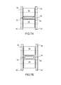
- the rollers 52 and 54 By choosing for the rollers 52 and 54, on the one hand and for the wheels 56 to 62 on the other hand, materials whose coefficients of respective thermal expansion are different, one can vary the spacing of the rollers 52 and 54, the dimensions of the space 64 and consequently the characteristic dimension of the restriction 34.
- a material whose coefficient of thermal expansion is greater than that of the wheels 56 to 62 For the rollers 52 and 54 a material whose coefficient of thermal expansion is greater than that of the wheels 56 to 62.
- the characteristic dimension of the restriction 34 is lower than at high temperature as shown in FIG. Figure 7A .
- the Figures 8A and 8B represent another example of means for varying a characteristic dimension of the restriction 34 adapted to the second embodiment shown in FIG. figure 6 .
- the restriction 34 may be partially obstructed by a needle 70.
- the needle is assembled at a first end 72 of a support 74 integral with the channel 30.
- the restriction 34 is, in turn, assembled at a second end 76
- a displacement of a nose 78 of the needle 70 which more or less obstructs the restriction 34 is obtained. function of fluid temperature variations as shown at high temperature on the figure 8A where the characteristic dimension of the restriction 34 is reduced compared to the Figure 8B , at lower temperature.
- FIGS. 9 to 12 represent another example of articulation comprising means for regulating the speed of its deployment.
- the channel 30 is integral with the cylindrical surface 24.
- a roller 80 rolls without sliding on the cylindrical surface 24.
- the roller 80 has a circular section and a diameter smaller than that of the cylindrical surface 24.
- the figure 9 to 12 represent the articulation in different positions from the stored position in figure 9 to the deployed position in figure 12 .
Landscapes
- Engineering & Computer Science (AREA)
- Remote Sensing (AREA)
- Aviation & Aerospace Engineering (AREA)
- Pivots And Pivotal Connections (AREA)
- Seats For Vehicles (AREA)
- Manipulator (AREA)
- Surgical Instruments (AREA)
Applications Claiming Priority (1)
| Application Number | Priority Date | Filing Date | Title |
|---|---|---|---|
| FR1005090A FR2969524B1 (fr) | 2010-12-23 | 2010-12-23 | Articulation auto-motorisee et ensemble articule auto-regules |
Publications (2)
| Publication Number | Publication Date |
|---|---|
| EP2468631A1 true EP2468631A1 (de) | 2012-06-27 |
| EP2468631B1 EP2468631B1 (de) | 2013-07-24 |
Family
ID=44318156
Family Applications (1)
| Application Number | Title | Priority Date | Filing Date |
|---|---|---|---|
| EP11194695.0A Active EP2468631B1 (de) | 2010-12-23 | 2011-12-20 | Mit einem eigenen Motorantrieb ausgestattetes Gelenk, und automatisch regulierte Gelenkanordnung |
Country Status (6)
| Country | Link |
|---|---|
| US (1) | US8992108B2 (de) |
| EP (1) | EP2468631B1 (de) |
| JP (1) | JP5877412B2 (de) |
| CN (1) | CN102582848B (de) |
| ES (1) | ES2428763T3 (de) |
| FR (1) | FR2969524B1 (de) |
Cited By (2)
| Publication number | Priority date | Publication date | Assignee | Title |
|---|---|---|---|---|
| FR2997385A1 (fr) * | 2012-10-26 | 2014-05-02 | Thales Sa | Systeme de motorisation pour articulation a pistes de roulement flexibles |
| CN107131204A (zh) * | 2017-06-29 | 2017-09-05 | 中国工程物理研究院总体工程研究所 | 一种用于保护罩的无销轴式铰链被动解脱机构 |
Families Citing this family (5)
| Publication number | Priority date | Publication date | Assignee | Title |
|---|---|---|---|---|
| FR2968234B1 (fr) * | 2010-12-07 | 2013-01-04 | Thales Sa | Systeme de motorisation a couple adapte pour structures spatiales deployables |
| FR2997384B1 (fr) * | 2012-10-26 | 2016-09-16 | Thales Sa | Systeme de motorisation pour articulation a moyens d'enroulement croises a roulement fiabilise |
| US9970517B2 (en) * | 2015-07-28 | 2018-05-15 | Northrop Grumman Systems Corporation | Satellite boom hinge actuator using drive chain with flexible and rigid characteristics |
| CN106184816B (zh) * | 2016-06-30 | 2017-07-04 | 清华大学深圳研究生院 | 一种航天器翻转机构的缓冲减速装置 |
| CN115258203B (zh) * | 2022-08-16 | 2024-01-26 | 重庆开拓卫星科技有限公司 | 一种绕轴展开的柔性太阳翼机构 |
Citations (6)
| Publication number | Priority date | Publication date | Assignee | Title |
|---|---|---|---|---|
| US4133502A (en) * | 1977-03-28 | 1979-01-09 | Rca Corporation | Plural panels deployed effectively as a single panel |
| FR2635077A1 (fr) | 1988-08-08 | 1990-02-09 | Aerospatiale | Articulation auto-motorisee, sans frottement, et ensemble articule tel qu'un panneau solaire de satellite equipe de telles articulations |
| EP0796785A2 (de) * | 1996-03-21 | 1997-09-24 | Construcciones Aeronauticas, S.A. | Geschwindigkeitsregler und mechanischer Motor für Anwendungen bei Satelliten in thermischem Vakuum |
| WO2001006145A2 (en) * | 1999-07-16 | 2001-01-25 | Swales Aerospace | Low shock anti-friction release device |
| EP1193406A2 (de) * | 2000-09-20 | 2002-04-03 | Sener, Ingenieria Y Sistemas, S.A. | Fernauslösemechanismus für Geräte mit geregelter Entfaltung und Auslösung |
| FR2902763A1 (fr) | 2006-06-23 | 2007-12-28 | Alcatel Sa | Articulation auto-motorisee pour ensemble articule tel qu'un panneau solaire de satellite |
Family Cites Families (9)
| Publication number | Priority date | Publication date | Assignee | Title |
|---|---|---|---|---|
| US3202061A (en) * | 1962-07-09 | 1965-08-24 | Lowell B Johnston | Fluid actuated displacement and positioning system |
| US3477662A (en) * | 1965-07-26 | 1969-11-11 | Trw Inc | Pneumatic tube deployment means,and solar cell therewith |
| AT340213B (de) * | 1976-01-23 | 1977-12-12 | Geislinger Dr Ing Leonard | Drehschwingungsdampfer bzw. schwingungsdampfende und drehelastische kupplung |
| JPS5746935Y2 (de) * | 1978-11-21 | 1982-10-15 | ||
| US5546632A (en) * | 1994-02-04 | 1996-08-20 | Orbital Sciences Corporation | Shear viscous damped hinge |
| DE19649741C2 (de) * | 1996-11-30 | 1999-07-15 | Daimler Benz Aerospace Ag | Gelenk zum Entfalten und Verriegeln einer Solarpaneele oder eines Reflektors |
| JP3820494B2 (ja) * | 1998-04-17 | 2006-09-13 | 株式会社竹中工務店 | アクチエータ内蔵型のヒンジ |
| JP2001039400A (ja) * | 1999-06-17 | 2001-02-13 | Daimlerchrysler Ag | 人工衛星太陽光発電機用拡開継手 |
| FR2968234B1 (fr) * | 2010-12-07 | 2013-01-04 | Thales Sa | Systeme de motorisation a couple adapte pour structures spatiales deployables |
-
2010
- 2010-12-23 FR FR1005090A patent/FR2969524B1/fr not_active Expired - Fee Related
-
2011
- 2011-12-20 US US13/332,032 patent/US8992108B2/en active Active
- 2011-12-20 EP EP11194695.0A patent/EP2468631B1/de active Active
- 2011-12-20 ES ES11194695T patent/ES2428763T3/es active Active
- 2011-12-23 CN CN201110463135.8A patent/CN102582848B/zh active Active
- 2011-12-26 JP JP2011283689A patent/JP5877412B2/ja active Active
Patent Citations (6)
| Publication number | Priority date | Publication date | Assignee | Title |
|---|---|---|---|---|
| US4133502A (en) * | 1977-03-28 | 1979-01-09 | Rca Corporation | Plural panels deployed effectively as a single panel |
| FR2635077A1 (fr) | 1988-08-08 | 1990-02-09 | Aerospatiale | Articulation auto-motorisee, sans frottement, et ensemble articule tel qu'un panneau solaire de satellite equipe de telles articulations |
| EP0796785A2 (de) * | 1996-03-21 | 1997-09-24 | Construcciones Aeronauticas, S.A. | Geschwindigkeitsregler und mechanischer Motor für Anwendungen bei Satelliten in thermischem Vakuum |
| WO2001006145A2 (en) * | 1999-07-16 | 2001-01-25 | Swales Aerospace | Low shock anti-friction release device |
| EP1193406A2 (de) * | 2000-09-20 | 2002-04-03 | Sener, Ingenieria Y Sistemas, S.A. | Fernauslösemechanismus für Geräte mit geregelter Entfaltung und Auslösung |
| FR2902763A1 (fr) | 2006-06-23 | 2007-12-28 | Alcatel Sa | Articulation auto-motorisee pour ensemble articule tel qu'un panneau solaire de satellite |
Cited By (4)
| Publication number | Priority date | Publication date | Assignee | Title |
|---|---|---|---|---|
| FR2997385A1 (fr) * | 2012-10-26 | 2014-05-02 | Thales Sa | Systeme de motorisation pour articulation a pistes de roulement flexibles |
| EP2724945A3 (de) * | 2012-10-26 | 2018-01-03 | Thales | Motorisierungssystem für Gelenk mit flexiblen Rollwegen |
| CN107131204A (zh) * | 2017-06-29 | 2017-09-05 | 中国工程物理研究院总体工程研究所 | 一种用于保护罩的无销轴式铰链被动解脱机构 |
| CN107131204B (zh) * | 2017-06-29 | 2023-03-14 | 中国工程物理研究院总体工程研究所 | 一种用于保护罩的无销轴式铰链被动解脱机构 |
Also Published As
| Publication number | Publication date |
|---|---|
| FR2969524A1 (fr) | 2012-06-29 |
| JP5877412B2 (ja) | 2016-03-08 |
| FR2969524B1 (fr) | 2013-09-06 |
| EP2468631B1 (de) | 2013-07-24 |
| JP2012132564A (ja) | 2012-07-12 |
| US20120321372A1 (en) | 2012-12-20 |
| CN102582848B (zh) | 2015-08-26 |
| US8992108B2 (en) | 2015-03-31 |
| CN102582848A (zh) | 2012-07-18 |
| ES2428763T3 (es) | 2013-11-11 |
Similar Documents
| Publication | Publication Date | Title |
|---|---|---|
| EP2468631B1 (de) | Mit einem eigenen Motorantrieb ausgestattetes Gelenk, und automatisch regulierte Gelenkanordnung | |
| EP2682655B1 (de) | Magnetventil mit flachem Kern und flacher Feder | |
| EP2463200B1 (de) | Motorisierungssystem mit angepasstem Drehmoment für entfaltbare Raumfahrtstrukturen | |
| FR3015358A1 (fr) | Roue spherique destinee a mouvoir un vehicule et vehicule mettant en œuvre la roue | |
| FR2902763A1 (fr) | Articulation auto-motorisee pour ensemble articule tel qu'un panneau solaire de satellite | |
| CA2763972A1 (fr) | Installation de convoyage comprenant au moins un couloir courbe | |
| EP2182156B1 (de) | Dämpfungsvorrichtung für Öffnungselement eines Militärfahrzeugs | |
| EP3491229A1 (de) | Belüftungsdurchflussregler für einen unter druck stehenden tank eines fahrzeugs | |
| FR3028842A1 (fr) | Structure deployable escamotable a metre-ruban | |
| EP3700811A1 (de) | Mechanismus zum öffnen/schliessen eines öffnungsblattes in bezug auf einen rahmen | |
| EP1914193A1 (de) | Scherenhebebühne | |
| EP2724945A2 (de) | Motorisierungssystem für Gelenk mit flexiblen Rollwegen | |
| FR2997384A1 (fr) | Systeme de motorisation pour articulation a moyens d'enroulement croises a roulement fiabilise | |
| EP3140562B1 (de) | Elektromechanischer stellantrieb mit kugelgewindetrieb für eine kupplung | |
| EP1266149A1 (de) | Hydraulischer dämpfer mit regelbarer dämpfungskennlinie | |
| FR2966857A1 (fr) | Dispositif de couverture de bassin | |
| WO2011026621A1 (fr) | Verin a cable et dispositif d'assistance aux personnes integrant un tel verin | |
| FR2593318A1 (fr) | Organe de memoire a disque magnetique | |
| FR3024495B1 (fr) | Dispositif de circulation d'air a debit ajustable pour turbomachine | |
| FR3024496A1 (fr) | Dispositif de circulation d'air a debit ajustable pour turbomachine d'aeronef | |
| FR2933760A1 (fr) | Dispositif d'actionnement de vanne a papillon | |
| FR3059752A1 (fr) | Moyen d'agrippement autobloquant d'un systeme de transmission continument variable | |
| FR3041724A1 (fr) | Dispositif limiteur de couple | |
| FR3019880A1 (fr) | Organe de liaison a limitation de couple ; volet, actionneur et appareil de climatisation comportant un tel organe de liaison | |
| EP2261588B1 (de) | Lagerungsvorrichtung eines Geschützturms |
Legal Events
| Date | Code | Title | Description |
|---|---|---|---|
| AK | Designated contracting states |
Kind code of ref document: A1 Designated state(s): AL AT BE BG CH CY CZ DE DK EE ES FI FR GB GR HR HU IE IS IT LI LT LU LV MC MK MT NL NO PL PT RO RS SE SI SK SM TR |
|
| AX | Request for extension of the european patent |
Extension state: BA ME |
|
| PUAI | Public reference made under article 153(3) epc to a published international application that has entered the european phase |
Free format text: ORIGINAL CODE: 0009012 |
|
| 17P | Request for examination filed |
Effective date: 20121214 |
|
| GRAP | Despatch of communication of intention to grant a patent |
Free format text: ORIGINAL CODE: EPIDOSNIGR1 |
|
| RIC1 | Information provided on ipc code assigned before grant |
Ipc: B64G 1/22 20060101AFI20130122BHEP |
|
| RIN1 | Information on inventor provided before grant (corrected) |
Inventor name: BAUDASSE, YANNICK Inventor name: VEZAIN, STEPHANE Inventor name: DUCARNE, JULILEN |
|
| GRAS | Grant fee paid |
Free format text: ORIGINAL CODE: EPIDOSNIGR3 |
|
| GRAA | (expected) grant |
Free format text: ORIGINAL CODE: 0009210 |
|
| AK | Designated contracting states |
Kind code of ref document: B1 Designated state(s): AL AT BE BG CH CY CZ DE DK EE ES FI FR GB GR HR HU IE IS IT LI LT LU LV MC MK MT NL NO PL PT RO RS SE SI SK SM TR |
|
| REG | Reference to a national code |
Ref country code: GB Ref legal event code: FG4D Free format text: NOT ENGLISH |
|
| REG | Reference to a national code |
Ref country code: CH Ref legal event code: EP |
|
| REG | Reference to a national code |
Ref country code: AT Ref legal event code: REF Ref document number: 623254 Country of ref document: AT Kind code of ref document: T Effective date: 20130815 |
|
| REG | Reference to a national code |
Ref country code: IE Ref legal event code: FG4D Free format text: LANGUAGE OF EP DOCUMENT: FRENCH |
|
| REG | Reference to a national code |
Ref country code: DE Ref legal event code: R096 Ref document number: 602011002446 Country of ref document: DE Effective date: 20130919 |
|
| REG | Reference to a national code |
Ref country code: ES Ref legal event code: FG2A Ref document number: 2428763 Country of ref document: ES Kind code of ref document: T3 Effective date: 20131111 |
|
| REG | Reference to a national code |
Ref country code: NL Ref legal event code: T3 |
|
| REG | Reference to a national code |
Ref country code: AT Ref legal event code: MK05 Ref document number: 623254 Country of ref document: AT Kind code of ref document: T Effective date: 20130724 |
|
| REG | Reference to a national code |
Ref country code: LT Ref legal event code: MG4D |
|
| PG25 | Lapsed in a contracting state [announced via postgrant information from national office to epo] |
Ref country code: AT Free format text: LAPSE BECAUSE OF FAILURE TO SUBMIT A TRANSLATION OF THE DESCRIPTION OR TO PAY THE FEE WITHIN THE PRESCRIBED TIME-LIMIT Effective date: 20130724 Ref country code: SE Free format text: LAPSE BECAUSE OF FAILURE TO SUBMIT A TRANSLATION OF THE DESCRIPTION OR TO PAY THE FEE WITHIN THE PRESCRIBED TIME-LIMIT Effective date: 20130724 Ref country code: HR Free format text: LAPSE BECAUSE OF FAILURE TO SUBMIT A TRANSLATION OF THE DESCRIPTION OR TO PAY THE FEE WITHIN THE PRESCRIBED TIME-LIMIT Effective date: 20130724 Ref country code: PT Free format text: LAPSE BECAUSE OF FAILURE TO SUBMIT A TRANSLATION OF THE DESCRIPTION OR TO PAY THE FEE WITHIN THE PRESCRIBED TIME-LIMIT Effective date: 20131125 Ref country code: CY Free format text: LAPSE BECAUSE OF FAILURE TO SUBMIT A TRANSLATION OF THE DESCRIPTION OR TO PAY THE FEE WITHIN THE PRESCRIBED TIME-LIMIT Effective date: 20130828 Ref country code: IS Free format text: LAPSE BECAUSE OF FAILURE TO SUBMIT A TRANSLATION OF THE DESCRIPTION OR TO PAY THE FEE WITHIN THE PRESCRIBED TIME-LIMIT Effective date: 20131124 Ref country code: NO Free format text: LAPSE BECAUSE OF FAILURE TO SUBMIT A TRANSLATION OF THE DESCRIPTION OR TO PAY THE FEE WITHIN THE PRESCRIBED TIME-LIMIT Effective date: 20131024 Ref country code: LT Free format text: LAPSE BECAUSE OF FAILURE TO SUBMIT A TRANSLATION OF THE DESCRIPTION OR TO PAY THE FEE WITHIN THE PRESCRIBED TIME-LIMIT Effective date: 20130724 |
|
| PG25 | Lapsed in a contracting state [announced via postgrant information from national office to epo] |
Ref country code: GR Free format text: LAPSE BECAUSE OF FAILURE TO SUBMIT A TRANSLATION OF THE DESCRIPTION OR TO PAY THE FEE WITHIN THE PRESCRIBED TIME-LIMIT Effective date: 20131025 Ref country code: PL Free format text: LAPSE BECAUSE OF FAILURE TO SUBMIT A TRANSLATION OF THE DESCRIPTION OR TO PAY THE FEE WITHIN THE PRESCRIBED TIME-LIMIT Effective date: 20130724 Ref country code: FI Free format text: LAPSE BECAUSE OF FAILURE TO SUBMIT A TRANSLATION OF THE DESCRIPTION OR TO PAY THE FEE WITHIN THE PRESCRIBED TIME-LIMIT Effective date: 20130724 Ref country code: SI Free format text: LAPSE BECAUSE OF FAILURE TO SUBMIT A TRANSLATION OF THE DESCRIPTION OR TO PAY THE FEE WITHIN THE PRESCRIBED TIME-LIMIT Effective date: 20130724 Ref country code: LV Free format text: LAPSE BECAUSE OF FAILURE TO SUBMIT A TRANSLATION OF THE DESCRIPTION OR TO PAY THE FEE WITHIN THE PRESCRIBED TIME-LIMIT Effective date: 20130724 |
|
| PG25 | Lapsed in a contracting state [announced via postgrant information from national office to epo] |
Ref country code: CY Free format text: LAPSE BECAUSE OF FAILURE TO SUBMIT A TRANSLATION OF THE DESCRIPTION OR TO PAY THE FEE WITHIN THE PRESCRIBED TIME-LIMIT Effective date: 20130724 |
|
| PG25 | Lapsed in a contracting state [announced via postgrant information from national office to epo] |
Ref country code: EE Free format text: LAPSE BECAUSE OF FAILURE TO SUBMIT A TRANSLATION OF THE DESCRIPTION OR TO PAY THE FEE WITHIN THE PRESCRIBED TIME-LIMIT Effective date: 20130724 Ref country code: CZ Free format text: LAPSE BECAUSE OF FAILURE TO SUBMIT A TRANSLATION OF THE DESCRIPTION OR TO PAY THE FEE WITHIN THE PRESCRIBED TIME-LIMIT Effective date: 20130724 Ref country code: SK Free format text: LAPSE BECAUSE OF FAILURE TO SUBMIT A TRANSLATION OF THE DESCRIPTION OR TO PAY THE FEE WITHIN THE PRESCRIBED TIME-LIMIT Effective date: 20130724 Ref country code: RO Free format text: LAPSE BECAUSE OF FAILURE TO SUBMIT A TRANSLATION OF THE DESCRIPTION OR TO PAY THE FEE WITHIN THE PRESCRIBED TIME-LIMIT Effective date: 20130724 Ref country code: DK Free format text: LAPSE BECAUSE OF FAILURE TO SUBMIT A TRANSLATION OF THE DESCRIPTION OR TO PAY THE FEE WITHIN THE PRESCRIBED TIME-LIMIT Effective date: 20130724 |
|
| PLBE | No opposition filed within time limit |
Free format text: ORIGINAL CODE: 0009261 |
|
| STAA | Information on the status of an ep patent application or granted ep patent |
Free format text: STATUS: NO OPPOSITION FILED WITHIN TIME LIMIT |
|
| BERE | Be: lapsed |
Owner name: THALES Effective date: 20131231 |
|
| 26N | No opposition filed |
Effective date: 20140425 |
|
| REG | Reference to a national code |
Ref country code: DE Ref legal event code: R097 Ref document number: 602011002446 Country of ref document: DE Effective date: 20140425 |
|
| PG25 | Lapsed in a contracting state [announced via postgrant information from national office to epo] |
Ref country code: LU Free format text: LAPSE BECAUSE OF FAILURE TO SUBMIT A TRANSLATION OF THE DESCRIPTION OR TO PAY THE FEE WITHIN THE PRESCRIBED TIME-LIMIT Effective date: 20131220 |
|
| REG | Reference to a national code |
Ref country code: IE Ref legal event code: MM4A |
|
| PG25 | Lapsed in a contracting state [announced via postgrant information from national office to epo] |
Ref country code: IE Free format text: LAPSE BECAUSE OF NON-PAYMENT OF DUE FEES Effective date: 20131220 Ref country code: BE Free format text: LAPSE BECAUSE OF NON-PAYMENT OF DUE FEES Effective date: 20131231 |
|
| PG25 | Lapsed in a contracting state [announced via postgrant information from national office to epo] |
Ref country code: MC Free format text: LAPSE BECAUSE OF FAILURE TO SUBMIT A TRANSLATION OF THE DESCRIPTION OR TO PAY THE FEE WITHIN THE PRESCRIBED TIME-LIMIT Effective date: 20130724 |
|
| PG25 | Lapsed in a contracting state [announced via postgrant information from national office to epo] |
Ref country code: SM Free format text: LAPSE BECAUSE OF FAILURE TO SUBMIT A TRANSLATION OF THE DESCRIPTION OR TO PAY THE FEE WITHIN THE PRESCRIBED TIME-LIMIT Effective date: 20130724 |
|
| PG25 | Lapsed in a contracting state [announced via postgrant information from national office to epo] |
Ref country code: TR Free format text: LAPSE BECAUSE OF FAILURE TO SUBMIT A TRANSLATION OF THE DESCRIPTION OR TO PAY THE FEE WITHIN THE PRESCRIBED TIME-LIMIT Effective date: 20130724 |
|
| PG25 | Lapsed in a contracting state [announced via postgrant information from national office to epo] |
Ref country code: RS Free format text: LAPSE BECAUSE OF FAILURE TO SUBMIT A TRANSLATION OF THE DESCRIPTION OR TO PAY THE FEE WITHIN THE PRESCRIBED TIME-LIMIT Effective date: 20131024 Ref country code: BG Free format text: LAPSE BECAUSE OF FAILURE TO SUBMIT A TRANSLATION OF THE DESCRIPTION OR TO PAY THE FEE WITHIN THE PRESCRIBED TIME-LIMIT Effective date: 20130724 Ref country code: MK Free format text: LAPSE BECAUSE OF FAILURE TO SUBMIT A TRANSLATION OF THE DESCRIPTION OR TO PAY THE FEE WITHIN THE PRESCRIBED TIME-LIMIT Effective date: 20130724 Ref country code: HU Free format text: LAPSE BECAUSE OF FAILURE TO SUBMIT A TRANSLATION OF THE DESCRIPTION OR TO PAY THE FEE WITHIN THE PRESCRIBED TIME-LIMIT; INVALID AB INITIO Effective date: 20111220 |
|
| REG | Reference to a national code |
Ref country code: CH Ref legal event code: PL |
|
| PG25 | Lapsed in a contracting state [announced via postgrant information from national office to epo] |
Ref country code: MT Free format text: LAPSE BECAUSE OF FAILURE TO SUBMIT A TRANSLATION OF THE DESCRIPTION OR TO PAY THE FEE WITHIN THE PRESCRIBED TIME-LIMIT Effective date: 20130724 |
|
| PG25 | Lapsed in a contracting state [announced via postgrant information from national office to epo] |
Ref country code: LI Free format text: LAPSE BECAUSE OF NON-PAYMENT OF DUE FEES Effective date: 20141231 Ref country code: CH Free format text: LAPSE BECAUSE OF NON-PAYMENT OF DUE FEES Effective date: 20141231 |
|
| REG | Reference to a national code |
Ref country code: FR Ref legal event code: PLFP Year of fee payment: 5 |
|
| REG | Reference to a national code |
Ref country code: FR Ref legal event code: PLFP Year of fee payment: 6 |
|
| REG | Reference to a national code |
Ref country code: FR Ref legal event code: PLFP Year of fee payment: 7 |
|
| PG25 | Lapsed in a contracting state [announced via postgrant information from national office to epo] |
Ref country code: AL Free format text: LAPSE BECAUSE OF FAILURE TO SUBMIT A TRANSLATION OF THE DESCRIPTION OR TO PAY THE FEE WITHIN THE PRESCRIBED TIME-LIMIT Effective date: 20130724 |
|
| PGFP | Annual fee paid to national office [announced via postgrant information from national office to epo] |
Ref country code: NL Payment date: 20231123 Year of fee payment: 13 |
|
| PGFP | Annual fee paid to national office [announced via postgrant information from national office to epo] |
Ref country code: GB Payment date: 20231116 Year of fee payment: 13 |
|
| PGFP | Annual fee paid to national office [announced via postgrant information from national office to epo] |
Ref country code: IT Payment date: 20231128 Year of fee payment: 13 Ref country code: FR Payment date: 20231122 Year of fee payment: 13 Ref country code: DE Payment date: 20231114 Year of fee payment: 13 |
|
| PGFP | Annual fee paid to national office [announced via postgrant information from national office to epo] |
Ref country code: ES Payment date: 20240116 Year of fee payment: 13 |