EP2468588A2 - Structure d'assemblage de balai d'essuie-glace - Google Patents
Structure d'assemblage de balai d'essuie-glace Download PDFInfo
- Publication number
- EP2468588A2 EP2468588A2 EP11182021A EP11182021A EP2468588A2 EP 2468588 A2 EP2468588 A2 EP 2468588A2 EP 11182021 A EP11182021 A EP 11182021A EP 11182021 A EP11182021 A EP 11182021A EP 2468588 A2 EP2468588 A2 EP 2468588A2
- Authority
- EP
- European Patent Office
- Prior art keywords
- support frame
- main arm
- space unit
- coupled
- replaceable
- Prior art date
- Legal status (The legal status is an assumption and is not a legal conclusion. Google has not performed a legal analysis and makes no representation as to the accuracy of the status listed.)
- Granted
Links
- 230000008878 coupling Effects 0.000 claims abstract description 48
- 238000010168 coupling process Methods 0.000 claims abstract description 48
- 238000005859 coupling reaction Methods 0.000 claims abstract description 48
- 230000003014 reinforcing effect Effects 0.000 claims description 12
- 239000000463 material Substances 0.000 claims description 6
- 229910000831 Steel Inorganic materials 0.000 claims description 4
- 239000010959 steel Substances 0.000 claims description 4
- 238000004519 manufacturing process Methods 0.000 abstract description 3
- 238000003780 insertion Methods 0.000 description 4
- 230000037431 insertion Effects 0.000 description 4
- 241000238631 Hexapoda Species 0.000 description 1
- 238000005260 corrosion Methods 0.000 description 1
- 230000007797 corrosion Effects 0.000 description 1
- 230000000694 effects Effects 0.000 description 1
- 238000001746 injection moulding Methods 0.000 description 1
- 238000000034 method Methods 0.000 description 1
- 238000000926 separation method Methods 0.000 description 1
- 239000000243 solution Substances 0.000 description 1
- 239000002699 waste material Substances 0.000 description 1
Images


Classifications
-
- B—PERFORMING OPERATIONS; TRANSPORTING
- B60—VEHICLES IN GENERAL
- B60S—SERVICING, CLEANING, REPAIRING, SUPPORTING, LIFTING, OR MANOEUVRING OF VEHICLES, NOT OTHERWISE PROVIDED FOR
- B60S1/00—Cleaning of vehicles
- B60S1/02—Cleaning windscreens, windows or optical devices
- B60S1/04—Wipers or the like, e.g. scrapers
- B60S1/32—Wipers or the like, e.g. scrapers characterised by constructional features of wiper blade arms or blades
- B60S1/38—Wiper blades
- B60S1/3801—Wiper blades characterised by a blade support harness consisting of several articulated elements
-
- B—PERFORMING OPERATIONS; TRANSPORTING
- B60—VEHICLES IN GENERAL
- B60S—SERVICING, CLEANING, REPAIRING, SUPPORTING, LIFTING, OR MANOEUVRING OF VEHICLES, NOT OTHERWISE PROVIDED FOR
- B60S1/00—Cleaning of vehicles
- B60S1/02—Cleaning windscreens, windows or optical devices
- B60S1/04—Wipers or the like, e.g. scrapers
- B60S1/32—Wipers or the like, e.g. scrapers characterised by constructional features of wiper blade arms or blades
- B60S1/40—Connections between blades and arms
- B60S1/4003—Multi-purpose connections for two or more kinds of arm ends
-
- B—PERFORMING OPERATIONS; TRANSPORTING
- B60—VEHICLES IN GENERAL
- B60S—SERVICING, CLEANING, REPAIRING, SUPPORTING, LIFTING, OR MANOEUVRING OF VEHICLES, NOT OTHERWISE PROVIDED FOR
- B60S1/00—Cleaning of vehicles
- B60S1/02—Cleaning windscreens, windows or optical devices
- B60S1/04—Wipers or the like, e.g. scrapers
- B60S1/32—Wipers or the like, e.g. scrapers characterised by constructional features of wiper blade arms or blades
- B60S1/40—Connections between blades and arms
- B60S1/4038—Connections between blades and arms for arms provided with a channel-shaped end
- B60S1/4045—Connections between blades and arms for arms provided with a channel-shaped end comprising a detachable intermediate element mounted on the channel-shaped end
- B60S1/4048—Connections between blades and arms for arms provided with a channel-shaped end comprising a detachable intermediate element mounted on the channel-shaped end the element being provided with retention means co-operating with the channel-shaped end of the arm
- B60S2001/4054—Connections between blades and arms for arms provided with a channel-shaped end comprising a detachable intermediate element mounted on the channel-shaped end the element being provided with retention means co-operating with the channel-shaped end of the arm the intermediate element engaging the back part of the arm
-
- B—PERFORMING OPERATIONS; TRANSPORTING
- B60—VEHICLES IN GENERAL
- B60S—SERVICING, CLEANING, REPAIRING, SUPPORTING, LIFTING, OR MANOEUVRING OF VEHICLES, NOT OTHERWISE PROVIDED FOR
- B60S1/00—Cleaning of vehicles
- B60S1/02—Cleaning windscreens, windows or optical devices
- B60S1/04—Wipers or the like, e.g. scrapers
- B60S1/32—Wipers or the like, e.g. scrapers characterised by constructional features of wiper blade arms or blades
- B60S1/40—Connections between blades and arms
- B60S2001/409—Connections between blades and arms characterised by the arm or connecting part mounted on the arm presenting a shaped opening for bearing the pivot axis
-
- B—PERFORMING OPERATIONS; TRANSPORTING
- B60—VEHICLES IN GENERAL
- B60S—SERVICING, CLEANING, REPAIRING, SUPPORTING, LIFTING, OR MANOEUVRING OF VEHICLES, NOT OTHERWISE PROVIDED FOR
- B60S1/00—Cleaning of vehicles
- B60S1/02—Cleaning windscreens, windows or optical devices
- B60S1/04—Wipers or the like, e.g. scrapers
- B60S1/32—Wipers or the like, e.g. scrapers characterised by constructional features of wiper blade arms or blades
- B60S1/40—Connections between blades and arms
- B60S2001/4093—Connections between blades and arms characterised by the mounting of the pivot on the main yoke of the blade
Definitions
- the present invention relates to a wiper blade assembly structure, and more particularly, to a wiper blade assembly structure which has a space unit formed in a certain area of a support frame, to which a main arm of a wiper is coupled, and allows a replaceable adaptor to be detachably attached to the space unit to thereby enable various types of main arms to be coupled to a single support frame together with the replaceable adaptor.
- a windshield wiper of automobiles is used to wipe off rain, snow or dirt or insects from a windshield for ensuring a driver's field of vision when it rains or snows while driving.
- the windshield wiper is an essential device for reducing occurrence of car accidents and securing safety of drivers while driving.
- the windshield wiper includes a main arm operating by a driving force supplied by a wiper motor, a support frame connected to the main arm and receiving the driving force therefrom and a wiper blade including a coupling groove coupled to the support frame.
- the wiper blade is closely adhered to the windshield and operates by the driving force transmitted from the main arm through the support frame to thereby remove dirt from the windshield.
- the wiper blade should operate by being closely adhered to the windshield to remove the dirt from the windshield. Accordingly, the main arm and the support frame are coupled to each other with the configuration to apply force so that the wiper blade is closely adhered to the windshield. Recently, additional devices are mounted in the automobile to increase the adherence of the wiper blade to the windshield to thereby prevent separation between the wiper blade and the windshield which may arise by air resistance or inertial force while driving.
- Such wiper blade operates by directly contacting the windshield and generally includes a soft rubber to protect the windshield.
- the wiper blade is closely adhered to the windshield, it is worn heavily by friction with the windshield, and is exposed to snow or rain and corrosion and crack may occur easily. Accordingly, the wiper blade should have such structure that a user may easily replace.
- the support frame varies depending on the specifications of the wiper main arm coupled to the support frame of the blade assembly structure, which causes inconvenience and unnecessary consumption of materials. That is, if the structure of the main arm varies depending on the type of automobiles, the wiper support frame coupled to the main arm should also be replaced accordingly. This causes inconvenience in use and raises costs due to waste of materials.
- the conventional wiper support frame is thick and includes a plastic material and weighs much.
- the present invention has been made to solve the problems and it is an object of the present invention to provide a wiper blade assembly structure which has a space unit formed in a certain area of a support frame, to which a main arm of a wiper is coupled, and allows a replaceable adaptor to be detachably attached to the space unit to thereby enable various types of main arms to be coupled to a single support frame together with the replaceable adaptor.
- a wiper blade assembly structure comprises a main arm which operates by a driving force supplied by a wiper motor; a support frame which is connected to the main arm and receives the driving force from the main arm and has a space unit formed in a certain size in an upper central part thereof and a lower coupling member formed in the space unit to be coupled to a replaceable adaptor; a replaceable adaptor which is detachably attached to the space unit of the support frame by a fixing means using the fixing pin and couples the main arm to the support frame; a blade fixer which is coupled to a lower part of the support frame; a blade which is coupled to the blade fixer; and the replaceable adaptor having a coupling part formed in a central part thereof to be detachably coupled to a front end coupling part of the main arm, and having a fixing pin inserting hole formed in a lower part thereof, into which the fixing pin of the support frame is inserted, and having a size to be inserted into an inside of the space unit
- the fixing means comprises at least one fixing pin to fix the replaceable adaptor in a vertical direction, and a hook member to fix the replaceable adaptor to the space unit of the support frame.
- the replaceable adaptor according to the present invention has a coupling part formed in a central part thereof to be detachably coupled to a front end coupling part of the main arm, and an upper coupling member corresponding to the lower coupling member formed in a lower side thereof, and has a size to be inserted into the inside of the space unit of the support frame.
- the lower coupling member of the support frame comprises at least one fixing pin to fie the replaceable adaptor in a vertical direction and a hook member which fixes the replaceable adaptor to the space unit of the support frame.
- the replaceable adaptor according to the present invention is replaced by other types of replaceable adaptors to be coupled to each main arm, depending on the type of the main arm.
- An insert reinforcing frame is installed in a internal lower side of the part where the replaceable adaptor of the support frame is installed and reinforces the strength of the support frame.
- the insert reinforcing frame comprises a steel material, and is formed in a longer length than the space unit of the support frame.
- the wiper blade assembly according to the present invention maintains consistent strength, and at the same time, connects various types of wiper main arms to a single blade assembly to thereby improve utilization and saves manufacturing costs since the wiper blade assembly does not need to vary depending on the type of the wiper main arm.
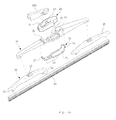
- FIG. 1 is a perspective view of a wiper blade assembly and a front end part of a main arm coupled to the wiper blade assembly according to the present invention.
- FIG. 2A is an exploded perspective view of the wiper blade assembly and the main arm in FIG. 1 .
- FIG. 2B is a front view of the wiper blade assembly and the main arm in FIG. 1 .
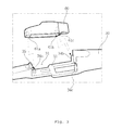
- FIG. 3 is an enlarged perspective view of a replaceable adaptor coupled to a space unit of a support frame according to the present invention.
- FIG. 4A is a perspective view of various types of replaceable adaptors coupled to the space unit of the support frame according to the present invention.
- FIG. 4B is a perspective view of a front end structure of the main arm coupled to each replaceable adaptor in FIG. 4A .
- FIG. 1 is a perspective view of a wiper blade assembly and a front end part of a main arm coupled to the wiper blade assembly according to the present invention.
- FIG. 2A is an exploded perspective view of the wiper blade assembly and the main arm in FIG. 1 .
- FIG. 2B is a front view of the wiper blade assembly and the main arm in FIG. 2A .
- FIG. 3 is an enlarged perspective view of a replaceable adaptor coupled to a space unit of a support frame according to the present invention.
- the wiper blade assembly structure includes a blade assembly 100 having a wiper blade 10 attached to a lower part thereof and a replaceable adaptor 60 coupled to an upper part thereof; and a main arm 200 whose front end coupling part is coupled to the replaceable adaptor 60 of the blade assembly 100.
- the wiper blade assembly 100 includes a support frame 30 which is connected to the main arm 200 to receive the driving force therefrom, has a space unit 31 (refer to FIG. 2A ) formed in a certain size in an upper central part thereof and a lower coupling member formed in a lower surface thereof to be coupled to a replaceable adaptor 60; the replaceable adaptor 60 which is detachably attached to the space unit 31 of the support frame 30 by a fixing means and couples the main arm 200 to the support frame 30; a blade fixer 20 which is coupled to a lower part of the support frame 30 and a blade 10 which is coupled to the blade fixer 30.
- the support frame 30 has the space unit 31 formed in a certain area of the upper part, e.g., in a central part thereof in a certain size, and the replaceable adaptor 60 is detachably attached to the space unit 31.
- the weight of the support frame 30 is reduced in proportion to the cut-off area.
- the insert reinforcing frame 50 preferably includes a thin steel material, which may reinforce the strength of the support frame 30 by using the thin strong steel while the thickness of the support frame 30 is thin.
- the insert reinforcing frame 50 is molded while being inserted into the support frame 30.
- the insert reinforcing frame 50 is provided in a lower part of an insertion space unit 31 into which the replaceable adaptor 60 is inserted, on the support frame, and is formed in a longer length than the space unit 31 to thereby reinforce the strength of the support frame 30.
- the insert reinforcing frame 50 has the space unit 51 formed in a certain part thereof, and a certain length of a central part 53 is flat to have the same configuration as that of the support frame 30, and opposite ends 55 and 57 are bent and project upwardly compared to the central part 53 as shown in FIG. 2A .
- the replaceable adaptor 60 has a coupling part formed in a central part thereof to be detachably coupled to a front end coupling part of the main arm, and an upper coupling member corresponding to the lower coupling member formed in a lower side thereof, and has a size to be inserted into the inside of the space unit of the support frame.
- the lower coupling member of the support frame 30 includes at least one of fixing pins 34a, 34b and 34c to fit and fixe the replaceable adaptor 60 in a vertical direction and a hook member 35 to fix the replaceable adaptor 60 to the support frame 30 concurrently with the replaceable adaptor 60 downwardly inserted into the space unit 31 of the support frame 30.
- the lower coupling member of the support frame 30 may be formed as a coupling member in a different type from the fixing pins 34a, 34b and 34c in one side wall of the space unit 31 of the support frame 30.
- the upper and lower coupling members may be formed to be vertically engaged with each other unlike the foregoing configuration.
- replaceable adaptor 60 should be replaced to other types of replaceable adaptors (refer to FIG. 4A ) to be coupled to each main arm, depending on the type of the main arm (refer to FIG. 4B ).
- the fixing pins 34a, 34b and 34c formed as an example of the lower coupling member in the support frame 30 are inserted into insertion grooves 61a, 61b and 61c formed in a lower side of the replaceable adaptor 60.
- the hook member 35 has an inclination surface 35a (refer to FIG. 2B ) formed in an upper part thereof, and is pushed back when the replaceable adaptor 60 moves downward, and projects forward concurrently with the completion of the insertion of the replaceable adaptor 60 to thereby fix the replaceable adaptor 60 inserted into the space unit 31 of the support frame 30.
- the hook member 35 is pulled back and the replaceable adaptor 60 is held upward. Then, the replaceable adaptor 60 is detached from the support frame 30.
- the fixing means of the replaceable adaptor 60 may have a different configuration from that described above. Not only the replaceable adaptor 60 with the foregoing configuration, but also other shapes of replaceable adaptors with different configurations may be coupled to the support frame 30. That is, if a coupling means is formed in a lower part of the replaceable adaptor with the different configuration corresponding to the fixing means of the replaceable adaptor according to the present exemplary embodiment, the replaceable adaptor may be coupled to the support frame 30.
- the space unit 31 of the support frame 30 has a configuration to accommodate various types of replaceable adaptors, e.g., replaceable adaptors 60a, 60b and 60c as shown in FIG. 4A , in addition to the replaceable adaptor 60 according to the present exemplary embodiment.
- the blade fixer 20 has the blade 10 attached to a lower part thereof.
- a conventional normal blade fixer having the blade 10 mounted in a lower part thereof is applicable and thus detailed description will be omitted.
- the replaceable adaptor 60 has a coupling part 61 formed in a central part thereof to be detachably coupled to a front end part of the main arm 20, and has fixing pin inserting holes 61a, 61b and 61c (refer to FIG. 3 ), formed in a lower part thereof, into which the fixing pins 34a, 34b and 34c of the support frame 30 are inserted and having a size to be inserted into the inside of the space unit 31 of the support frame 30.
- a front end coupling part 210 (refer to FIG. 2B ) of the main arm 200 is inserted into the coupling part 61 of the replaceable adaptor 60.
- a fixing shaft inserting groove 211 of the main arm 200 is coupled to a fixing shaft 63 (refer to FIG. 2A ) provided in the inside of the coupling part 61 of the replaceable adaptor 60, and the fixing shaft inserting groove 211 is rounded inwardly and surrounds the fixing shaft 63 provided in the replaceable adaptor 60.
- a hook member coupling part 65 formed in a side of the replaceable adaptor 60 is coupled to the hook member 35 and has an appropriate thickness according to the size of the hook member 35.
- the shape of the replaceable adaptor 60 according to the present invention is not limited to that according to the present exemplary embodiment, and may vary. Also, the configuration of the front end coupling part 210 of the main arm 200 coupled to the replaceable adaptor 60 may vary accordingly.
- the configuration of connecting the main arm 200 to the coupling part 61 provided in the replaceable adaptor 60 according to the present invention may be embodied by the conventional art, and detailed description will be omitted.
- the replaceable adaptor 60 is located in an upper part of the space unit 31 of the support frame 30 to couple the replaceable adaptor 60 to the space unit 31 formed in the support frame 30.
- the fixing pins 34a, 34b and 34c formed in a lower surface 33 of the space unit 31 of the support frame 30 are inserted into the fixing pin inserting holes 61a, 61b and 61c provided in the lower part of the replaceable adaptor 60.
- the hook member 25 is pulled back, and projects forward concurrently with the completion of the insertion of the replaceable adaptor 60 and the replaceable adaptor 60 is locked while being inserted.
- An upper step (not shown) of the hook member 35 in the above state is located in the hook member coupling part 65 refer to FIG. 2B ) of the replaceable adaptor 60.
- the inclination surface 35a is formed in an upper part of the hook member 35 and enables the replaceable adaptor 60 to be easily inserted into the space unit 31 of the support frame 30.
- FIGS. 4A and 4B illustrate various types of replaceable adaptors according to exemplary embodiments of the present invention and a configuration of the front end coupling part of the main arm coupled to the coupling part of the replaceable adaptors.
- FIG. 4A is a perspective view of the various types of the replaceable adaptors coupled to the space unit of the support frame according to the present invention.
- FIG. 4B illustrates a configuration of the front end coupling part of the main arm coupled to the replaceable adaptors in FIG. 4A .
- the replaceable adaptors 60, 60a, 60b and 60c in FIG. 4A have different shapes, and may be detachably attached to the same support frame 30. Accordingly, the shape of the front end coupling part of the main arms 200, 200a, 200b and 200c coupled to the replaceable adaptors 60, 60a, 60b and 60c varies.
- the wiper blade assembly structure according to the present invention has the space unit formed in the certain area of the support frame coupled to the main arm of the wiper, and has the replaceable adaptor detachably attached to the space unit to thereby couple various types of main arms to a single support frame.
- the wiper blade assembly according to the present invention connects various types of wiper main arms to a single blade assembly to thereby improve utilization of the wiper and saves manufacturing costs.
Landscapes
- Engineering & Computer Science (AREA)
- Mechanical Engineering (AREA)
- Ink Jet (AREA)
- Brushes (AREA)
- Cleaning In General (AREA)
Applications Claiming Priority (1)
| Application Number | Priority Date | Filing Date | Title |
|---|---|---|---|
| KR1020100132623A KR101238492B1 (ko) | 2010-12-22 | 2010-12-22 | 와이퍼 블레이드 조립체 구조 |
Publications (3)
| Publication Number | Publication Date |
|---|---|
| EP2468588A2 true EP2468588A2 (fr) | 2012-06-27 |
| EP2468588A3 EP2468588A3 (fr) | 2017-11-01 |
| EP2468588B1 EP2468588B1 (fr) | 2019-08-14 |
Family
ID=44674517
Family Applications (1)
| Application Number | Title | Priority Date | Filing Date |
|---|---|---|---|
| EP11182021.3A Active EP2468588B1 (fr) | 2010-12-22 | 2011-09-20 | Structure d'assemblage de balai d'essuie-glace |
Country Status (4)
| Country | Link |
|---|---|
| US (1) | US8978192B2 (fr) |
| EP (1) | EP2468588B1 (fr) |
| KR (1) | KR101238492B1 (fr) |
| CN (1) | CN102529894B (fr) |
Cited By (2)
| Publication number | Priority date | Publication date | Assignee | Title |
|---|---|---|---|---|
| DE102012108340A1 (de) * | 2011-09-07 | 2013-03-07 | Kcw Corporation | Wischerblattbaugruppe |
| FR3049916A1 (fr) * | 2016-04-12 | 2017-10-13 | Valeo Systemes Dessuyage | Capuchon equipant un connecteur pour un balai d'essuyage d'un vehicule automobile |
Families Citing this family (29)
| Publication number | Priority date | Publication date | Assignee | Title |
|---|---|---|---|---|
| US20130227809A1 (en) | 2012-02-24 | 2013-09-05 | Pylon Manufacturing Corp. | Wiper blade |
| USD706200S1 (en) | 2010-09-22 | 2014-06-03 | Pylon Manufacturing Corporation | Windshield wiper cover |
| US9457768B2 (en) | 2011-04-21 | 2016-10-04 | Pylon Manufacturing Corp. | Vortex damping wiper blade |
| US9174609B2 (en) | 2011-04-21 | 2015-11-03 | Pylon Manufacturing Corp. | Wiper blade with cover |
| MX345011B (es) | 2011-07-28 | 2017-01-11 | Pylon Mfg Corp | Adaptador, conector y conjunto de limpiaparabrisas. |
| MX347284B (es) | 2011-07-29 | 2017-04-21 | Pylon Mfg Corp | Conector de limpiaparabrisas. |
| US9108595B2 (en) | 2011-07-29 | 2015-08-18 | Pylon Manufacturing Corporation | Windshield wiper connector |
| US8806700B2 (en) | 2011-07-29 | 2014-08-19 | Pylon Manufacturing Corporation | Wiper blade connector |
| US9481343B2 (en) * | 2011-12-14 | 2016-11-01 | Federal-Mogul Corporation | Windscreen wiper device |
| US20130219649A1 (en) | 2012-02-24 | 2013-08-29 | Pylon Manufacturing Corp. | Wiper blade |
| US9145111B2 (en) * | 2012-09-10 | 2015-09-29 | Alberee Products, Inc. | Hybrid blade |
| US10829092B2 (en) | 2012-09-24 | 2020-11-10 | Pylon Manufacturing Corp. | Wiper blade with modular mounting base |
| US10166951B2 (en) | 2013-03-15 | 2019-01-01 | Pylon Manufacturing Corp. | Windshield wiper connector |
| CN103707853B (zh) * | 2014-01-13 | 2016-08-31 | 丹阳威利塑胶有限公司 | 一种汽车后窗雨刷器 |
| KR101511319B1 (ko) * | 2014-02-21 | 2015-04-14 | 에이디엠이십일 주식회사 | 와이퍼 블레이드 |
| US9505380B2 (en) | 2014-03-07 | 2016-11-29 | Pylon Manufacturing Corp. | Windshield wiper connector and assembly |
| US9539987B2 (en) | 2014-04-01 | 2017-01-10 | Trico Products Corporation | Wiper adapter and wiper assembly incorporating the same |
| USD777079S1 (en) | 2014-10-03 | 2017-01-24 | Pylon Manufacturing Corp. | Wiper blade frame |
| USD787308S1 (en) | 2014-10-03 | 2017-05-23 | Pylon Manufacturing Corp. | Wiper blade package |
| WO2017075066A1 (fr) | 2015-10-26 | 2017-05-04 | Pylon Manufacturing Corp. | Balai d'essuie-glace |
| CN109311450A (zh) | 2016-05-19 | 2019-02-05 | 电缆塔制造有限公司 | 挡风玻璃雨刮器连接器 |
| AU2017268008A1 (en) | 2016-05-19 | 2018-11-22 | Pylon Manufacturing Corp. | Windshield wiper connector |
| CN109311451B (zh) | 2016-05-19 | 2022-08-23 | 电缆塔制造有限公司 | 挡风玻璃雨刮器片 |
| WO2017201458A1 (fr) | 2016-05-19 | 2017-11-23 | Pylon Manufacturing Corp. | Raccord d'essuie-glace |
| US11040705B2 (en) | 2016-05-19 | 2021-06-22 | Pylon Manufacturing Corp. | Windshield wiper connector |
| WO2018081791A1 (fr) | 2016-10-31 | 2018-05-03 | Pylon Manufacturing Corp. | Balai d'essuie-glace pourvu d'une coiffe |
| KR102076111B1 (ko) * | 2018-08-06 | 2020-02-11 | 주식회사 캐프 | 와이퍼장치 |
| FR3091233B1 (fr) | 2018-12-27 | 2021-04-02 | Valeo Systemes Dessuyage | Adaptateur pour monture de balai d’essuyage de véhicule automobile |
| CA3074387A1 (fr) * | 2019-03-08 | 2020-09-08 | Levolor, Inc. | Ensemble de traverse basse pour revetement de structure architecturale et procedes d`assemblage associes |
Family Cites Families (16)
| Publication number | Priority date | Publication date | Assignee | Title |
|---|---|---|---|---|
| US3179969A (en) * | 1963-10-04 | 1965-04-27 | Tridon Mfg Ltd | Automobile windshield wiper backing members |
| US4118825A (en) * | 1977-03-28 | 1978-10-10 | Monroe Auto Equipment Company | Connector assembly for windshield wipers |
| US4324019A (en) * | 1980-05-13 | 1982-04-13 | The Anderson Company Of Indiana | Windshield wiper connecting pin adaptor |
| FR2574732B1 (fr) * | 1984-12-18 | 1987-12-18 | Champion Spark Plug Europ | Dispositif d'attache pour balais d'essuie-glace |
| JP2557021Y2 (ja) * | 1993-04-05 | 1997-12-08 | マルエヌ株式会社 | ワイパーブレードの連結具 |
| DE69522105T2 (de) * | 1995-09-11 | 2002-04-11 | Cooper Automotive S.A., Aubange | Wischblatt und Verfahren zu dessen Herstellung |
| JP2003011789A (ja) * | 2001-06-29 | 2003-01-15 | Ichikoh Ind Ltd | 車両用ワイパー |
| FR2854851A1 (fr) * | 2003-05-13 | 2004-11-19 | Sylvain Pasquet | Piece de liaison articulee entre bras et balai d'essuie glace. |
| JP4038798B2 (ja) | 2003-08-28 | 2008-01-30 | 自動車電機工業株式会社 | 車両用ワイパ |
| JP2005075240A (ja) * | 2003-09-02 | 2005-03-24 | Pia Kk | ワイパー装置におけるブレード取付け構造 |
| FR2879986B1 (fr) * | 2004-12-23 | 2008-07-11 | Valeo Systemes Dessuyage | Balai d'essuie-glace plat universel et connecteur amovible associe |
| KR100988344B1 (ko) | 2008-08-25 | 2010-10-18 | 주식회사 캐프 | 공기압력 완충부를 구비한 차량용 플랫 와이퍼 |
| KR100999126B1 (ko) | 2009-03-12 | 2010-12-07 | 주식회사 캐프 | 와이퍼 블레이드 조립체 |
| KR100937206B1 (ko) | 2009-06-02 | 2010-01-19 | 동양기전 주식회사 | 자동차 와이퍼 조립체 |
| JP3157246U (ja) | 2009-11-24 | 2010-02-04 | 復岡有限公司 | ワイパーブレード |
| CN102582584B (zh) * | 2011-01-14 | 2014-08-27 | 东莞鸿益雨刷有限公司 | 雨刷架及其制造方法 |
-
2010
- 2010-12-22 KR KR1020100132623A patent/KR101238492B1/ko active IP Right Grant
-
2011
- 2011-09-20 EP EP11182021.3A patent/EP2468588B1/fr active Active
- 2011-09-24 US US13/244,361 patent/US8978192B2/en active Active
- 2011-10-17 CN CN201110314079.1A patent/CN102529894B/zh active Active
Non-Patent Citations (1)
| Title |
|---|
| None |
Cited By (2)
| Publication number | Priority date | Publication date | Assignee | Title |
|---|---|---|---|---|
| DE102012108340A1 (de) * | 2011-09-07 | 2013-03-07 | Kcw Corporation | Wischerblattbaugruppe |
| FR3049916A1 (fr) * | 2016-04-12 | 2017-10-13 | Valeo Systemes Dessuyage | Capuchon equipant un connecteur pour un balai d'essuyage d'un vehicule automobile |
Also Published As
| Publication number | Publication date |
|---|---|
| US20120159733A1 (en) | 2012-06-28 |
| KR20120071046A (ko) | 2012-07-02 |
| EP2468588A3 (fr) | 2017-11-01 |
| KR101238492B1 (ko) | 2013-03-11 |
| EP2468588B1 (fr) | 2019-08-14 |
| CN102529894A (zh) | 2012-07-04 |
| CN102529894B (zh) | 2015-07-22 |
| US8978192B2 (en) | 2015-03-17 |
Similar Documents
| Publication | Publication Date | Title |
|---|---|---|
| EP2468588B1 (fr) | Structure d'assemblage de balai d'essuie-glace | |
| CA2843527C (fr) | Adaptateur, raccord et ensemble d'essuie-glace | |
| KR101591651B1 (ko) | 플랫 와이퍼 블레이드 조립체 및 그 결합방법 | |
| US20120180244A1 (en) | Multi-adapter for a vehicle wiper | |
| EP2569190B1 (fr) | Ensemble essuie-glace à balai profilé | |
| CA2810711C (fr) | Coupleur universel pour un ensemble essuie-glace a balai a lames | |
| US20070136975A1 (en) | Wiper arm and cover for a wiper arm | |
| KR100586056B1 (ko) | 와이퍼 암의 연결장치 | |
| EP2271526A1 (fr) | Balai d essuie-glace pour automobile | |
| US9067569B2 (en) | Wiper blade apparatus capable of assembling various mount types of wiper arms | |
| US8176595B2 (en) | Saddle bracket for wiper adapter | |
| JP6538653B2 (ja) | ウインドスクリーンワイパーデバイスのための接続デバイス | |
| KR101212283B1 (ko) | 엔드 캡 구조가 개선된 플랫 블레이드 타입 와이퍼 장치 | |
| KR100999126B1 (ko) | 와이퍼 블레이드 조립체 | |
| KR101156740B1 (ko) | 차량용 와이퍼 장치 | |
| KR20110034994A (ko) | 차량 와이퍼용 멀티 어댑터 | |
| US20060021179A1 (en) | Universal adapter for a windshield wiper | |
| JP2019051852A (ja) | ワイパブレード | |
| CN210554679U (zh) | 一种雨刷接头及适配该雨刷接头的雨刷 | |
| EP2730471A2 (fr) | Élément d'attache pour assembler différents types de montage de bras d'essuie-glace | |
| CN214775774U (zh) | 一种橡胶条可更换的雨刮器 | |
| CN109910824B (zh) | 刮水附件、刮水片和车辆 | |
| KR101220461B1 (ko) | 플랫 블레이드 타입 와이퍼용 커넥터 장치 | |
| KR200445232Y1 (ko) | 스포일러 부재 및 이를 구비한 와이퍼 블레이드 | |
| CN212098767U (zh) | 新型汽车雨刷 |
Legal Events
| Date | Code | Title | Description |
|---|---|---|---|
| 17P | Request for examination filed |
Effective date: 20110923 |
|
| AK | Designated contracting states |
Kind code of ref document: A2 Designated state(s): AL AT BE BG CH CY CZ DE DK EE ES FI FR GB GR HR HU IE IS IT LI LT LU LV MC MK MT NL NO PL PT RO RS SE SI SK SM TR |
|
| AX | Request for extension of the european patent |
Extension state: BA ME |
|
| PUAI | Public reference made under article 153(3) epc to a published international application that has entered the european phase |
Free format text: ORIGINAL CODE: 0009012 |
|
| PUAL | Search report despatched |
Free format text: ORIGINAL CODE: 0009013 |
|
| AK | Designated contracting states |
Kind code of ref document: A3 Designated state(s): AL AT BE BG CH CY CZ DE DK EE ES FI FR GB GR HR HU IE IS IT LI LT LU LV MC MK MT NL NO PL PT RO RS SE SI SK SM TR |
|
| AX | Request for extension of the european patent |
Extension state: BA ME |
|
| RIC1 | Information provided on ipc code assigned before grant |
Ipc: B60S 1/38 20060101AFI20170928BHEP Ipc: B60S 1/40 20060101ALI20170928BHEP |
|
| RAX | Requested extension states of the european patent have changed |
Extension state: ME Payment date: 20180502 Extension state: BA Payment date: 20180502 |
|
| STAA | Information on the status of an ep patent application or granted ep patent |
Free format text: STATUS: EXAMINATION IS IN PROGRESS |
|
| 17Q | First examination report despatched |
Effective date: 20180822 |
|
| GRAP | Despatch of communication of intention to grant a patent |
Free format text: ORIGINAL CODE: EPIDOSNIGR1 |
|
| STAA | Information on the status of an ep patent application or granted ep patent |
Free format text: STATUS: GRANT OF PATENT IS INTENDED |
|
| INTG | Intention to grant announced |
Effective date: 20190306 |
|
| GRAS | Grant fee paid |
Free format text: ORIGINAL CODE: EPIDOSNIGR3 |
|
| GRAA | (expected) grant |
Free format text: ORIGINAL CODE: 0009210 |
|
| STAA | Information on the status of an ep patent application or granted ep patent |
Free format text: STATUS: THE PATENT HAS BEEN GRANTED |
|
| AK | Designated contracting states |
Kind code of ref document: B1 Designated state(s): AL AT BE BG CH CY CZ DE DK EE ES FI FR GB GR HR HU IE IS IT LI LT LU LV MC MK MT NL NO PL PT RO RS SE SI SK SM TR |
|
| AX | Request for extension of the european patent |
Extension state: BA ME |
|
| REG | Reference to a national code |
Ref country code: GB Ref legal event code: FG4D |
|
| REG | Reference to a national code |
Ref country code: CH Ref legal event code: EP Ref country code: AT Ref legal event code: REF Ref document number: 1166660 Country of ref document: AT Kind code of ref document: T Effective date: 20190815 |
|
| REG | Reference to a national code |
Ref country code: DE Ref legal event code: R096 Ref document number: 602011061219 Country of ref document: DE |
|
| REG | Reference to a national code |
Ref country code: IE Ref legal event code: FG4D |
|
| REG | Reference to a national code |
Ref country code: NL Ref legal event code: MP Effective date: 20190814 |
|
| REG | Reference to a national code |
Ref country code: LT Ref legal event code: MG4D |
|
| PG25 | Lapsed in a contracting state [announced via postgrant information from national office to epo] |
Ref country code: NO Free format text: LAPSE BECAUSE OF FAILURE TO SUBMIT A TRANSLATION OF THE DESCRIPTION OR TO PAY THE FEE WITHIN THE PRESCRIBED TIME-LIMIT Effective date: 20191114 Ref country code: BG Free format text: LAPSE BECAUSE OF FAILURE TO SUBMIT A TRANSLATION OF THE DESCRIPTION OR TO PAY THE FEE WITHIN THE PRESCRIBED TIME-LIMIT Effective date: 20191114 Ref country code: NL Free format text: LAPSE BECAUSE OF FAILURE TO SUBMIT A TRANSLATION OF THE DESCRIPTION OR TO PAY THE FEE WITHIN THE PRESCRIBED TIME-LIMIT Effective date: 20190814 Ref country code: HR Free format text: LAPSE BECAUSE OF FAILURE TO SUBMIT A TRANSLATION OF THE DESCRIPTION OR TO PAY THE FEE WITHIN THE PRESCRIBED TIME-LIMIT Effective date: 20190814 Ref country code: SE Free format text: LAPSE BECAUSE OF FAILURE TO SUBMIT A TRANSLATION OF THE DESCRIPTION OR TO PAY THE FEE WITHIN THE PRESCRIBED TIME-LIMIT Effective date: 20190814 Ref country code: PT Free format text: LAPSE BECAUSE OF FAILURE TO SUBMIT A TRANSLATION OF THE DESCRIPTION OR TO PAY THE FEE WITHIN THE PRESCRIBED TIME-LIMIT Effective date: 20191216 Ref country code: FI Free format text: LAPSE BECAUSE OF FAILURE TO SUBMIT A TRANSLATION OF THE DESCRIPTION OR TO PAY THE FEE WITHIN THE PRESCRIBED TIME-LIMIT Effective date: 20190814 Ref country code: LT Free format text: LAPSE BECAUSE OF FAILURE TO SUBMIT A TRANSLATION OF THE DESCRIPTION OR TO PAY THE FEE WITHIN THE PRESCRIBED TIME-LIMIT Effective date: 20190814 |
|
| REG | Reference to a national code |
Ref country code: AT Ref legal event code: MK05 Ref document number: 1166660 Country of ref document: AT Kind code of ref document: T Effective date: 20190814 |
|
| PG25 | Lapsed in a contracting state [announced via postgrant information from national office to epo] |
Ref country code: ES Free format text: LAPSE BECAUSE OF FAILURE TO SUBMIT A TRANSLATION OF THE DESCRIPTION OR TO PAY THE FEE WITHIN THE PRESCRIBED TIME-LIMIT Effective date: 20190814 Ref country code: AL Free format text: LAPSE BECAUSE OF FAILURE TO SUBMIT A TRANSLATION OF THE DESCRIPTION OR TO PAY THE FEE WITHIN THE PRESCRIBED TIME-LIMIT Effective date: 20190814 Ref country code: LV Free format text: LAPSE BECAUSE OF FAILURE TO SUBMIT A TRANSLATION OF THE DESCRIPTION OR TO PAY THE FEE WITHIN THE PRESCRIBED TIME-LIMIT Effective date: 20190814 Ref country code: IS Free format text: LAPSE BECAUSE OF FAILURE TO SUBMIT A TRANSLATION OF THE DESCRIPTION OR TO PAY THE FEE WITHIN THE PRESCRIBED TIME-LIMIT Effective date: 20191214 Ref country code: RS Free format text: LAPSE BECAUSE OF FAILURE TO SUBMIT A TRANSLATION OF THE DESCRIPTION OR TO PAY THE FEE WITHIN THE PRESCRIBED TIME-LIMIT Effective date: 20190814 Ref country code: GR Free format text: LAPSE BECAUSE OF FAILURE TO SUBMIT A TRANSLATION OF THE DESCRIPTION OR TO PAY THE FEE WITHIN THE PRESCRIBED TIME-LIMIT Effective date: 20191115 |
|
| PG25 | Lapsed in a contracting state [announced via postgrant information from national office to epo] |
Ref country code: TR Free format text: LAPSE BECAUSE OF FAILURE TO SUBMIT A TRANSLATION OF THE DESCRIPTION OR TO PAY THE FEE WITHIN THE PRESCRIBED TIME-LIMIT Effective date: 20190814 |
|
| PG25 | Lapsed in a contracting state [announced via postgrant information from national office to epo] |
Ref country code: RO Free format text: LAPSE BECAUSE OF FAILURE TO SUBMIT A TRANSLATION OF THE DESCRIPTION OR TO PAY THE FEE WITHIN THE PRESCRIBED TIME-LIMIT Effective date: 20190814 Ref country code: PL Free format text: LAPSE BECAUSE OF FAILURE TO SUBMIT A TRANSLATION OF THE DESCRIPTION OR TO PAY THE FEE WITHIN THE PRESCRIBED TIME-LIMIT Effective date: 20190814 Ref country code: AT Free format text: LAPSE BECAUSE OF FAILURE TO SUBMIT A TRANSLATION OF THE DESCRIPTION OR TO PAY THE FEE WITHIN THE PRESCRIBED TIME-LIMIT Effective date: 20190814 Ref country code: EE Free format text: LAPSE BECAUSE OF FAILURE TO SUBMIT A TRANSLATION OF THE DESCRIPTION OR TO PAY THE FEE WITHIN THE PRESCRIBED TIME-LIMIT Effective date: 20190814 Ref country code: IT Free format text: LAPSE BECAUSE OF FAILURE TO SUBMIT A TRANSLATION OF THE DESCRIPTION OR TO PAY THE FEE WITHIN THE PRESCRIBED TIME-LIMIT Effective date: 20190814 Ref country code: DK Free format text: LAPSE BECAUSE OF FAILURE TO SUBMIT A TRANSLATION OF THE DESCRIPTION OR TO PAY THE FEE WITHIN THE PRESCRIBED TIME-LIMIT Effective date: 20190814 |
|
| PG25 | Lapsed in a contracting state [announced via postgrant information from national office to epo] |
Ref country code: MC Free format text: LAPSE BECAUSE OF FAILURE TO SUBMIT A TRANSLATION OF THE DESCRIPTION OR TO PAY THE FEE WITHIN THE PRESCRIBED TIME-LIMIT Effective date: 20190814 Ref country code: IS Free format text: LAPSE BECAUSE OF FAILURE TO SUBMIT A TRANSLATION OF THE DESCRIPTION OR TO PAY THE FEE WITHIN THE PRESCRIBED TIME-LIMIT Effective date: 20200224 Ref country code: SM Free format text: LAPSE BECAUSE OF FAILURE TO SUBMIT A TRANSLATION OF THE DESCRIPTION OR TO PAY THE FEE WITHIN THE PRESCRIBED TIME-LIMIT Effective date: 20190814 Ref country code: SK Free format text: LAPSE BECAUSE OF FAILURE TO SUBMIT A TRANSLATION OF THE DESCRIPTION OR TO PAY THE FEE WITHIN THE PRESCRIBED TIME-LIMIT Effective date: 20190814 Ref country code: CZ Free format text: LAPSE BECAUSE OF FAILURE TO SUBMIT A TRANSLATION OF THE DESCRIPTION OR TO PAY THE FEE WITHIN THE PRESCRIBED TIME-LIMIT Effective date: 20190814 |
|
| REG | Reference to a national code |
Ref country code: CH Ref legal event code: PL |
|
| REG | Reference to a national code |
Ref country code: DE Ref legal event code: R097 Ref document number: 602011061219 Country of ref document: DE |
|
| PLBE | No opposition filed within time limit |
Free format text: ORIGINAL CODE: 0009261 |
|
| STAA | Information on the status of an ep patent application or granted ep patent |
Free format text: STATUS: NO OPPOSITION FILED WITHIN TIME LIMIT |
|
| PG2D | Information on lapse in contracting state deleted |
Ref country code: IS |
|
| PG25 | Lapsed in a contracting state [announced via postgrant information from national office to epo] |
Ref country code: IE Free format text: LAPSE BECAUSE OF NON-PAYMENT OF DUE FEES Effective date: 20190920 Ref country code: LU Free format text: LAPSE BECAUSE OF NON-PAYMENT OF DUE FEES Effective date: 20190920 Ref country code: LI Free format text: LAPSE BECAUSE OF NON-PAYMENT OF DUE FEES Effective date: 20190930 Ref country code: CH Free format text: LAPSE BECAUSE OF NON-PAYMENT OF DUE FEES Effective date: 20190930 |
|
| 26N | No opposition filed |
Effective date: 20200603 |
|
| REG | Reference to a national code |
Ref country code: BE Ref legal event code: MM Effective date: 20190930 |
|
| PG25 | Lapsed in a contracting state [announced via postgrant information from national office to epo] |
Ref country code: BE Free format text: LAPSE BECAUSE OF NON-PAYMENT OF DUE FEES Effective date: 20190930 Ref country code: SI Free format text: LAPSE BECAUSE OF FAILURE TO SUBMIT A TRANSLATION OF THE DESCRIPTION OR TO PAY THE FEE WITHIN THE PRESCRIBED TIME-LIMIT Effective date: 20190814 |
|
| GBPC | Gb: european patent ceased through non-payment of renewal fee |
Effective date: 20191114 |
|
| PG25 | Lapsed in a contracting state [announced via postgrant information from national office to epo] |
Ref country code: GB Free format text: LAPSE BECAUSE OF NON-PAYMENT OF DUE FEES Effective date: 20191114 |
|
| PG25 | Lapsed in a contracting state [announced via postgrant information from national office to epo] |
Ref country code: CY Free format text: LAPSE BECAUSE OF FAILURE TO SUBMIT A TRANSLATION OF THE DESCRIPTION OR TO PAY THE FEE WITHIN THE PRESCRIBED TIME-LIMIT Effective date: 20190814 |
|
| PG25 | Lapsed in a contracting state [announced via postgrant information from national office to epo] |
Ref country code: MT Free format text: LAPSE BECAUSE OF FAILURE TO SUBMIT A TRANSLATION OF THE DESCRIPTION OR TO PAY THE FEE WITHIN THE PRESCRIBED TIME-LIMIT Effective date: 20190814 Ref country code: HU Free format text: LAPSE BECAUSE OF FAILURE TO SUBMIT A TRANSLATION OF THE DESCRIPTION OR TO PAY THE FEE WITHIN THE PRESCRIBED TIME-LIMIT; INVALID AB INITIO Effective date: 20110920 |
|
| PG25 | Lapsed in a contracting state [announced via postgrant information from national office to epo] |
Ref country code: MK Free format text: LAPSE BECAUSE OF FAILURE TO SUBMIT A TRANSLATION OF THE DESCRIPTION OR TO PAY THE FEE WITHIN THE PRESCRIBED TIME-LIMIT Effective date: 20190814 |
|
| P01 | Opt-out of the competence of the unified patent court (upc) registered |
Effective date: 20230530 |
|
| PGFP | Annual fee paid to national office [announced via postgrant information from national office to epo] |
Ref country code: FR Payment date: 20230918 Year of fee payment: 13 |
|
| PGFP | Annual fee paid to national office [announced via postgrant information from national office to epo] |
Ref country code: DE Payment date: 20231124 Year of fee payment: 13 |