EP2468153A1 - Kaffeemaschine und Kaffeemaschine / Kaffeekannen-Anordnung - Google Patents
Kaffeemaschine und Kaffeemaschine / Kaffeekannen-Anordnung Download PDFInfo
- Publication number
- EP2468153A1 EP2468153A1 EP11194442A EP11194442A EP2468153A1 EP 2468153 A1 EP2468153 A1 EP 2468153A1 EP 11194442 A EP11194442 A EP 11194442A EP 11194442 A EP11194442 A EP 11194442A EP 2468153 A1 EP2468153 A1 EP 2468153A1
- Authority
- EP
- European Patent Office
- Prior art keywords
- coffee
- housing
- coffee pot
- coffee machine
- handle
- Prior art date
- Legal status (The legal status is an assumption and is not a legal conclusion. Google has not performed a legal analysis and makes no representation as to the accuracy of the status listed.)
- Granted
Links
Images

Classifications
-
- A—HUMAN NECESSITIES
- A47—FURNITURE; DOMESTIC ARTICLES OR APPLIANCES; COFFEE MILLS; SPICE MILLS; SUCTION CLEANERS IN GENERAL
- A47J—KITCHEN EQUIPMENT; COFFEE MILLS; SPICE MILLS; APPARATUS FOR MAKING BEVERAGES
- A47J31/00—Apparatus for making beverages
- A47J31/44—Parts or details or accessories of beverage-making apparatus
- A47J31/4403—Constructional details
- A47J31/4407—Lids, covers or knobs
-
- A—HUMAN NECESSITIES
- A47—FURNITURE; DOMESTIC ARTICLES OR APPLIANCES; COFFEE MILLS; SPICE MILLS; SUCTION CLEANERS IN GENERAL
- A47J—KITCHEN EQUIPMENT; COFFEE MILLS; SPICE MILLS; APPARATUS FOR MAKING BEVERAGES
- A47J31/00—Apparatus for making beverages
- A47J31/44—Parts or details or accessories of beverage-making apparatus
- A47J31/4403—Constructional details
Definitions
- the present invention relates to a coffee machine, in particular to a receiving structure of a coffee machine for a coffee pot.
- the invention further relates to a coffee machine / coffee pot arrangement.
- Previously known coffee machines include, as in the Chinese patent application CN201452866 is shown, a housing and a housing arranged on the cover plate. This is connected via a fixed pivot axis with the housing so that the cover plate is movable relative to the housing and thus can be opened or closed.
- a coffee grounds container In the upper area within the housing is a coffee grounds container, above which there is a nozzle connected to a water tank. With this nozzle, the coffee grounds container can be filled with hot water to prepare coffee by mixing the water with the ground coffee.
- a receiving space for the associated coffee pot is formed. After the coffee pot has been inserted into the receiving space, a valve located in the bottom region of the coffee grounds container and projecting out of the housing is pushed upwards by the head of the coffee pot, so that the coffee can flow from the coffee grounds container into the can.
- the coffee pot supplied with a coffee maker is usually made of glass.
- the coffee pot is inserted with outwardly facing handle in the coffee machine, so that the handle is located in the edge region of the package. So it can come to damage or destruction of the handle, the axis of rotation of the can lid or even the glass jug because of the occurring during transport shocks or vibrations.
- This risk has been avoided by the fact that the packaging is larger and at the same time the handle is packed with additional or reinforced packaging. This inevitably involves increased costs, without however resolving the problems from the ground up.
- the object of the present invention is to propose a coffee machine with a receiving space for the handle of the associated coffee pot, with which simplifies the packaging of coffee maker and coffee pot and the risk of damage during transport can be avoided.
- a further object of the present invention is to propose a coffee machine / coffee pot arrangement in which the coffee machine has a receiving space for the handle of the associated coffee pot and with which simplifies the packaging of coffee maker and coffee pot and the risk of damage during transport can be avoided.
- a coffee machine comprising a housing in which a receiving space for a coffee pot is formed.
- a receiving space for a coffee pot is formed in the housing also connected to the receiving space receiving groove is provided for the handle of a coffee pot.
- the receiving groove is formed as a recess of the inner wall of the receiving space in the housing.
- the inner wall of the housing is a curved surface, wherein the depth direction of the groove corresponds to the radial direction of the curved surface.
- the longitudinal direction of the receiving groove corresponds to the height direction of the housing.
- the object is further achieved by a coffee machine / coffee pot arrangement, which consists of a coffee pot and a coffee machine.
- the coffee pot has a jug body and a handle protruding from the jug body.
- the coffee maker includes a housing in which a receiving space for the cup body of the coffee pot is formed. In this case, the handle of the coffee pot is received within the housing of the coffee maker.
- a receiving groove for the handle of the coffee pot is formed in an inner wall of the housing located in the receiving space.
- the inner wall of the housing is a curved surface, wherein the depth direction of the receiving groove corresponds to the radial direction of the curved surface.
- the longitudinal direction of the receiving groove corresponds to the height direction of the housing.
- the present invention offers the following advantages: Because the handle of the coffee pot can be fitted into the housing of the coffee machine, only relatively small-sized and less robust packaging means have to be used, which means a cost saving. Moreover, the handle of the coffee pot is fixed by the housing of the coffee machine in its position, so that the coffee pot is not damaged due to accidental movement during transport.
- FIG. 1 shows an embodiment of a coffee machine according to the invention and its associated coffee pot.
- the coffee machine 10 comprises an upright housing 11 and a cover plate 12 arranged on the upper side of the housing 11, while the coffee pot 20 has a can body 21 and a handle 22 projecting laterally from a side wall of the can body.
- the housing 11 has in its lower region a receiving space 15 for the can body 21 of the coffee pot.
- the inner wall 111 of the housing 11 located in the receiving space is a curved surface in which a receiving groove 112 is formed whose depth direction corresponds to the radial direction of the curved surface and whose longitudinal direction corresponds to the height direction of the housing 11.
- the receiving space 15, after the coffee pot 20 has been inserted into the housing 11, serve to receive the jug body 21 of the coffee pot and the receiving groove 112 for receiving the handle 22 of the coffee pot.
- the handle of the coffee pot is fixed by the housing of the coffee machine in its position, so that the coffee pot is not damaged due to accidental movement during transport.
- the coffee maker further includes an opening and closing unit formed between a cover plate 12 and a housing 11.
- This in turn comprises a fixedly attached to the housing 11, first pivot axis 131, a second pivot axis 132, which allows the cover 12 pivotal movement, and a first and second pivot axis 131, 132 connecting coupling rod 13.
- the opening and closing unit comprises a slider 14, which is accommodated on the one hand in the intermediate space 122 of the guide rails 121 and slides along the guide rails 121.
- the slider 14 is fixedly connected to the second pivot axis 132.
- the cover plate 12 can be opened with a small angle to the housing 11 and at the same time move downwards relative to the housing 11, so that the cover plate is at least partially below an upper edge of the housing 11.
- the area of the cover plate, which lies below the upper edge of the housing assumes an even greater proportion, the farther the cover plate is opened. In this way, the height by which the cover plate protrudes beyond the upper edge of the housing can be kept small over the entire opening process. In other words, a complete opening of the cover plate can be ensured, even if the coffee machine is in a vertically limited space.
- FIG. 4 shows a further embodiment of an opening and closing unit for a coffee machine, which differs from the embodiment according to FIG. 3 essentially in that no slide is provided here. Instead, the two ends of the second pivot axis 132 extend into the guide rails 121, so that the second pivot axis 132 can slide along the guide rails 121. At the same time, the cover plate 12 may also rotate about the second pivot axis 132. With this configuration, the same effects as in the opening and closing structure according to FIG. 3 can be achieved.
- the opening and closing unit can also be designed as a multi-joint linkage, which supports a continuous, direction-changing movement of the cover plate during opening, so that the cover plate is located for the most part below the upper edge of the housing. This also makes it possible to reduce the height of the cover plate above the upper edge of the housing when the cover plate is fully open.
Landscapes
- Engineering & Computer Science (AREA)
- Food Science & Technology (AREA)
- Apparatus For Making Beverages (AREA)
Abstract
Description
- Die vorliegende Erfindung bezieht sich auf eine Kaffeemaschine, insbesondere auf eine Aufnahmestruktur einer Kaffeemaschine für eine Kaffeekanne.
- Die Erfindung betrifft weiterhin eine Kaffeemaschine / Kaffeekannen-Anordnung.
- Bisher bekannte Kaffeemaschinen umfassen, wie in der chinesischen Offenlegungsschrift
CN201452866 gezeigt ist, ein Gehäuse und eine am Gehäuse angeordnete Abdeckplatte. Diese ist über eine feste Schwenkachse mit dem Gehäuse so verbunden, dass die Abdeckplatte relativ zum Gehäuse bewegbar ist und somit geöffnet oder geschlossen werden kann. Im oberen Bereich innerhalb des Gehäuses befindet sich ein Kaffeemehlbehälter, oberhalb dessen eine mit einem Wasserbehälter verbundene Düse vorhanden ist. Mit dieser Düse kann der Kaffeemehlbehälter mit Heißwasser befüllt werden, um durch Mischung des Wassers mit dem Kaffeemehl Kaffee zu bereiten. Im unteren Bereich des Gehäuses ist ein Aufnahmeraum für die zugehörige Kaffeekanne ausgebildet. Nachdem die Kaffeekanne in den Aufnahmeraum eingesetzt worden ist, wird ein im Bodenbereich des Kaffeemehlbehälters befindliches und aus dem Gehäuse herausragendes Ventil durch den Kopf der Kaffeekanne nach oben gedrückt, so dass der Kaffee aus dem Kaffeemehlbehälter in die Kanne einfließen kann. - Die bei einer Kaffeemaschine mitgelieferte Kaffeekanne besteht in der Regel aus Glas. Beim Verpacken wird die Kaffeekanne mit nach außen weisendem Handgriff in die Kaffeemaschine eingesetzt, so dass sich der Handgriff im Randbereich der Verpackung befindet. So kann es wegen der während des Transportes auftretenden Stöße bzw. Schwingungen zur Beschädigung oder Zerstörung des Handgriffs, der Drehachse des Kannendeckels oder sogar der Glaskanne kommen. Diese Gefahr wurde bisher dadurch vermieden, dass die Verpackung größer dimensioniert ist und zugleich der Handgriff mit zusätzlichen bzw. verstärkten Packmitteln verpackt wird. Damit sind unvermeidlich erhöhte Kosten verbunden, ohne dass jedoch die Probleme von Grund auf behoben würden.
- Zur Lösung der genannten Probleme ist es notwendig, bekannte Kaffeemaschinen zu verbessern.
- Die Aufgabe der vorliegenden Erfindung besteht darin, eine Kaffeemaschine mit einem Aufnahmeraum für den Handgriff der zugehörigen Kaffeekanne vorzuschlagen, mit der die Verpackung von Kaffeemaschine und Kaffeekanne vereinfacht und die Beschädigungsgefahr beim Transport vermieden werden kann.
- Eine weitere Aufgabe der vorliegenden Erfindung ist es, eine Kaffeemaschine /Kaffeekannen-Anordnung vorzuschlagen, bei dem die Kaffeemaschine einen Aufnahmeraum für den Handgriff der zugehörigen Kaffeekanne aufweist und mit dem die Verpackung von Kaffeemaschine und Kaffeekanne vereinfacht und die Beschädigungsgefahr beim Transport vermieden werden kann.
- Erfindungsgemäß wird die Aufgabe durch eine Kaffeemaschine gelöst, die ein Gehäuse umfasst, in dem ein Aufnahmeraum für eine Kaffeekanne ausgebildet ist. Im Gehäuse ist ferner eine mit dem Aufnahmeraum verbundene Aufnahmenut für den Handgriff einer Kaffeekanne vorgesehen.
- In einer weiteren Weiterbildung der vorliegenden Erfindung ist die Aufnahmenut als Vertiefung der Innenwand des Aufnahmeraums im Gehäuse ausgebildet.
- In einer weiteren Weiterbildung der vorliegenden Erfindung handelt es sich bei der Innenwand des Gehäuses um eine gekrümmte Fläche, wobei die Tiefenrichtung der Nut der radialen Richtung der gekrümmten Fläche entspricht.
- In einer weiteren Weiterbildung der vorliegenden Erfindung entspricht die Längsrichtung der Aufnahmenut der Höhenrichtung des Gehäuses.
- Erfindungsgemäß wird die Aufgabe weiterhin durch eine Kaffeemaschine / Kaffeekannen-Anordnung gelöst, die aus einer Kaffeekanne und einer Kaffeemaschine besteht. Die Kaffeekanne weist einen Kannenkörper und einen vom Kannenkörper hervorragenden Handgriff auf. Die Kaffeemaschine umfasst ein Gehäuse, in dem ein Aufnahmeraum für den Kannenkörper der Kaffeekanne ausgebildet ist. Dabei ist der Handgriff der Kaffeekanne innerhalb des Gehäuses der Kaffeemaschine aufgenommen.
- In einer weiteren Weiterbildung der vorliegenden Erfindung ist in einer sich im Aufnahmeraum befindenden Innenwand des Gehäuses eine Aufnahmenut für den Handgriff der Kaffeekanne ausgebildet.
- In einer weiteren Weiterbildung der vorliegenden Erfindung handelt es sich bei der Innenwand des Gehäuses um eine gekrümmte Fläche, wobei die Tiefenrichtung der Aufnahmenut der radialen Richtung der gekrümmten Fläche entspricht.
- In einer weiteren Weiterbildung der vorliegenden Erfindung entspricht die Längsrichtung der Aufnahmenut der Höhenrichtung des Gehäuses.
- Im Vergleich zum Stand der Technik bietet die vorliegende Erfindung nachfolgende Vorteile: Dadurch, dass sich der Handgriff der Kaffeekanne ins Gehäuse der Kaffeemaschine einpassen lässt, müssen nur verhältnismäßig klein dimensionierte und weniger robuste Packmittel eingesetzt werden, was eine Kosteneinsparung bedeutet. Überdies ist der Handgriff der Kaffeekanne durch das Gehäuse der Kaffeemaschine in seiner Lage fixiert, so dass die Kaffeekanne nicht wegen unbeabsichtigter Bewegungen während des Transportes beschädigt wird.
- Es zeigen
- ABB 1
- in räumlicher Darstellung eine Ausführungsform einer Kaffeemaschine /Kaffeekannen-Anordnung,
- ABB 2
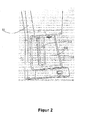
- in räumlicher Darstellung einen Teilbereich der Kaffeemaschine gemäß ABB 1 zur Aufnahme einer Kaffeekanne,
- ABB 3
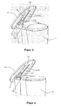
- in räumlicher Darstellung die Beweglichkeit einer Abdeckplatte relativ zu einem Gehäuse bei der Kaffeemaschine gemäß ABB 1, wobei eine Ausführungsform einer zwischen Abdeckplatte und Gehäuse befindlichen Öffnungs- und Schließstruktur mit dargestellt ist, und
- ABB 4
- in ähnlicher Darstellung wie ABB 3 eine weitere Ausführungsform der Öffnungs-und Schließstruktur.
- In ABB 1 ist eine Ausführungsform einer erfindungsgemäßen Kaffeemaschine und ihrer zugehörigen Kaffeekanne dargestellt. Hierbei umfasst die Kaffeemaschine 10 ein aufrecht stehendes Gehäuse 11 und eine an der Oberseite des Gehäuses 11 angeordnete Abdeckplatte 12, während die Kaffeekanne 20 einen Kannenkörper 21 und einen von einer Seitenwand des Kannenkörpers seitlich hervorragenden Handgriff 22 aufweist. Wie auch aus ABB 2 zu ersehen ist, verfügt das Gehäuse 11 in seinem unteren Bereich über einen Aufnahmeraum 15 für den Kannenkörper 21 der Kaffeekanne. Bei der sich im Aufnahmeraum befindenden Innenwand 111 des Gehäuses 11 handelt es sich um eine gekrümmte Fläche, in der eine Aufnahmenut 112 ausgebildet ist, deren Tiefenrichtung der radialen Richtung der gekrümmten Fläche und deren Längsrichtung der Höhenrichtung des Gehäuses 11 entspricht. So kann der Aufnahmeraum 15, nachdem die Kaffeekanne 20 ins Gehäuse 11 eingesetzt worden ist, zur Aufnahme des Kannenkörpers 21 der Kaffeekanne und die Aufnahmenut 112 zur Aufnahme des Handgriffs 22 der Kaffeekanne dienen. Dadurch, dass sich der Handgriff der Kaffeekanne ins Gehäuse der Kaffeemaschine einpassen lässt, müssen nur verhältnismäßig klein dimensionierte und weniger robuste Packmittel eingesetzt werden, was eine Kosteneinsparung bedeutet. Überdies ist der Handgriff der Kaffeekanne durch das Gehäuse der Kaffeemaschine in seiner Lage fixiert, so dass die Kaffeekanne nicht wegen unbeabsichtigter Bewegungen während des Transportes beschädigt wird.
- Gemäß der Ausführungsform in ABB 3 umfasst die Kaffeemaschine ferner eine zwischen Abdeckplatte 12 und Gehäuse 11 ausgebildete Öffnungs- und Schließeinheit. Diese umfasst wiederum eine fest am Gehäuse 11 angebrachte, erste Schwenkachse 131, eine zweite Schwenkachse 132, die der Abdeckplatte 12 eine Schwenkbewegung erlaubt, sowie eine die erste und zweite Schwenkachse 131, 132 verbindende Koppelstange 13. An der Innenwand der Abdeckplatte 12 sind weiterhin zwei voneinander beabstandet angeordnete Führungsschienen 121 vorhanden. Zusätzlich hierzu umfasst die Öffnungs-und Schließeinheit einen Schieber 14, der einerseits in dem Zwischenraum 122 der Führungsschienen 121 aufgenommen ist und entlang den Führungsschienen 121 gleitet. Andererseits ist der Schieber 14 fest mit der zweiten Schwenkachse 132 verbunden. Durch eine solche Anordnung kann die Abdeckplatte 12 mit einem kleinen Winkel zum Gehäuse 11 geöffnet werden und sich zugleich gegenüber dem Gehäuse 11 nach unten bewegen, so dass sich die Abdeckplatte zumindest teilweise unterhalb einer Oberkante des Gehäuses 11 befindet. Zudem nimmt der Bereich der Abdeckplatte, der unterhalb der Oberkante des Gehäuses liegt, einen umso größeren Anteil ein, je weiter die Abdeckplatte geöffnet wird. Auf diese Weise kann die Höhe, um die die Abdeckplatte über die Oberkante des Gehäuses herausragt, über den gesamten Öffnungsvorgang klein gehalten werden. Mit anderen Worten kann eine völlige Öffnung der Abdeckplatte gewährleistet werden, selbst wenn sich die Kaffeemaschine in einem vertikal begrenzten Raum befindet.
- ABB 4 zeigt eine weitere Ausführungsform einer Öffnungs- und Schließeinheit für eine Kaffeemaschine, welche sich von der Ausführungsform gemäß ABB 3 im Wesentlichen dadurch unterscheidet, dass hier kein Schieber vorgesehen ist. Stattdessen erstrecken sich die beiden Enden der zweiten Schwenkachse 132 bis in die Führungsschienen 121, so dass die zweite Schwenkachse 132 entlang den Führungsschienen 121 gleiten kann. Gleichzeitig dazu kann sich die Abdeckplatte 12 auch um die zweite Schwenkachse 132 drehen. Mit dieser Ausgestaltung können die gleichen Effekte wie bei der gemäß ABB 3 ausgeführten Öffnungs- und Schließstruktur erzielt werden.
- Es liegt den Fachleuchten auf diesem Gebiet nahe, dass auch die folgenden Varianten dieselbe technische Wirkung wie bei der in ABB 3 oder 4 offenbarten Ausführungsform erzielen: Es kann vorgesehen sein, dass die zweite Schwenkachse fest mit der Abdeckplatte verbunden ist, während sich die Führungsschienen am Gehäuse befinden, wobei die erste Schwenkachse dann als in den Führungsschienen verschiebbar ausgeführt ist. Darüber hinaus ist es denkbar, dass neben einer festen Verbindung zwischen erster Schwenkachse und Gehäuse auch die zweite Schwenkachse und die Abdeckplatte miteinander fest verbunden sind. Dies wirkt sich zwar nicht so gut aus wie die Ausführungsform gemäß ABB 3 oder 4, kann jedoch die Höhe der Abdeckplatte oberhalb der Oberkante des Gehäuses bei völlig geöffneter Abdeckplatte bis zu einem gewissen Grad reduzieren. Des Weiteren kann die Öffnungs- und Schließeinheit auch als Mehrgelenkgestänge ausgeführt sein, das eine kontinuierliche, richtungswechselnde Bewegung der Abdeckplatte während des Öffnens unterstützt, damit sich die Abdeckplatte zum größten Teil unterhalb der Oberkante des Gehäuses befindet. Auch dadurch lässt sich die Höhe der Abdeckplatte oberhalb der Oberkante des Gehäuses bei völlig geöffneter Abdeckplatte verringern.
- Bisher wurden Ausführungsformen der vorliegenden Erfindung dargestellt und beschrieben, die jedoch nicht jeweils nur auf eine separate Ausgestaltung beschränkt sind. Im Rahmen der vorliegenden Erfindung können vielmehr die in den einzelnen Ausführungsformen offenbarten Ausgestaltungen auf geeignete Weise miteinander zu anderen, den Fachleuten auf diesem Gebiet naheliegenden Ausführungsformen kombiniert werden.
- Das oben Beschriebene stellt keine Einschränkung der Erfindung dar, sondern dient lediglich der beispielhaften Darstellung möglicher Ausführungsformen der Erfindung. Trotz der vorangehenden Beschreibung und Erläuterung am Beispiel einer Filterkaffeemaschine kann die vorliegende Erfindung auch bei anderen Kaffeemaschinentypen Verwendung finden. Jede gleichwertige Ausführung oder Variation, welche von den Grundideen der Erfindung ausgeht, ist daher vom Schutzumfang der vorliegenden Erfindung umfasst.
Claims (8)
- Kaffeemaschine, umfassend ein Gehäuse, in dem ein Aufnahmeraum für eine Kaffeekanne ausgebildet ist, dadurch gekennzeichnet, dass im Gehäuse ferner eine mit dem Aufnahmeraum verbundene Aufnahmenut für den Handgriff der Kaffeekanne vorgesehen ist.
- Kaffeemaschine gemäß Anspruch 1, dadurch gekennzeichnet, dass die Aufnahmenut als Vertiefung der Innenwand des Aufnahmeraums im Gehäuse ausgebildet ist.
- Kaffeemaschine gemäß Anspruch 2, dadurch gekennzeichnet, dass es sich bei der Innenwand des Gehäuses um eine gekrümmte Fläche handelt, wobei die Tiefenrichtung der Nut der radialen Richtung der gekrümmten Fläche entspricht.
- Kaffeemaschine gemäß Anspruch 1, dadurch gekennzeichnet, dass die Längsrichtung der Aufnahmenut der Höhenrichtung des Gehäuses entspricht.
- Kaffeemaschine / Kaffeekannen-Anordnung, bestehend aus einer Kaffeekanne, die einen Kannenkörper und einen vom Kannenkörper hervorragenden Handgriff aufweist, und einer Kaffeemaschine mit einem Gehäuse, in dem ein Aufnahmeraum für den Kannenkörper der Kaffeekanne ausgebildet ist, dadurch gekennzeichnet, dass der Handgriff der Kaffeekanne innerhalb des Gehäuses der Kaffeemaschine aufgenommen ist.
- Kaffeemaschine / Kaffeekannen-Anordnung gemäß Anspruch 5, dadurch gekennzeichnet, dass in einer sich im Aufnahmeraum befindenden Innenwand des Gehäuses eine Aufnahmenut für den Handgriff der Kaffeekanne ausgebildet ist.
- Kaffeemaschine / Kaffeekannen-Anordnung gemäß Anspruch 6, dadurch gekennzeichnet, dass es sich bei der Innenwand des Gehäuses um eine gekrümmte Fläche handelt, wobei die Tiefenrichtung der Aufnahmenut der radialen Richtung der gekrümmten Fläche entspricht.
- Kaffeemaschine / Kaffeekannen-Anordnung gemäß Anspruch 6, dadurch gekennzeichnet, dass die Längsrichtung der Aufnahmenut der Höhenrichtung des Gehäuses entspricht.
Applications Claiming Priority (1)
| Application Number | Priority Date | Filing Date | Title |
|---|---|---|---|
| CN2010206807562U CN201977567U (zh) | 2010-12-24 | 2010-12-24 | 咖啡机及咖啡机和咖啡壶的组件 |
Publications (2)
| Publication Number | Publication Date |
|---|---|
| EP2468153A1 true EP2468153A1 (de) | 2012-06-27 |
| EP2468153B1 EP2468153B1 (de) | 2014-06-18 |
Family
ID=44605042
Family Applications (1)
| Application Number | Title | Priority Date | Filing Date |
|---|---|---|---|
| EP11194442.7A Active EP2468153B1 (de) | 2010-12-24 | 2011-12-20 | Kaffeemaschine |
Country Status (2)
| Country | Link |
|---|---|
| EP (1) | EP2468153B1 (de) |
| CN (1) | CN201977567U (de) |
Citations (5)
| Publication number | Priority date | Publication date | Assignee | Title |
|---|---|---|---|---|
| US6357342B1 (en) * | 2000-09-11 | 2002-03-19 | Simatelex Manufactory Co., Ltd. | Electric coffee maker |
| US20050145112A1 (en) * | 2004-01-06 | 2005-07-07 | Paul Scribner | Top load coffee maker with front access water reservoir |
| US20080282896A1 (en) * | 2007-05-17 | 2008-11-20 | Electrical & Electronics Ltd. | Beverage brewing apparatus with pump dispensing system |
| US20090120300A1 (en) * | 2007-11-09 | 2009-05-14 | Herbst Andrew F | Method, system and apparatus for housing and dispensing liquid |
| CN201452866U (zh) | 2009-02-06 | 2010-05-12 | 广东亿龙电器股份有限公司 | 一种咖啡机 |
-
2010
- 2010-12-24 CN CN2010206807562U patent/CN201977567U/zh not_active Expired - Lifetime
-
2011
- 2011-12-20 EP EP11194442.7A patent/EP2468153B1/de active Active
Patent Citations (5)
| Publication number | Priority date | Publication date | Assignee | Title |
|---|---|---|---|---|
| US6357342B1 (en) * | 2000-09-11 | 2002-03-19 | Simatelex Manufactory Co., Ltd. | Electric coffee maker |
| US20050145112A1 (en) * | 2004-01-06 | 2005-07-07 | Paul Scribner | Top load coffee maker with front access water reservoir |
| US20080282896A1 (en) * | 2007-05-17 | 2008-11-20 | Electrical & Electronics Ltd. | Beverage brewing apparatus with pump dispensing system |
| US20090120300A1 (en) * | 2007-11-09 | 2009-05-14 | Herbst Andrew F | Method, system and apparatus for housing and dispensing liquid |
| CN201452866U (zh) | 2009-02-06 | 2010-05-12 | 广东亿龙电器股份有限公司 | 一种咖啡机 |
Also Published As
| Publication number | Publication date |
|---|---|
| EP2468153B1 (de) | 2014-06-18 |
| CN201977567U (zh) | 2011-09-21 |
Similar Documents
| Publication | Publication Date | Title |
|---|---|---|
| EP0283569B1 (de) | Elektrisch betriebene Kaffeemaschine | |
| DE202011110593U1 (de) | Behälter mit übereinander klappbaren Seitenwänden | |
| DE102005012896B4 (de) | Fahrzeugsitz mit Kopfstütze | |
| EP3305141B1 (de) | Kaffeevollautomat | |
| DE3446916A1 (de) | Fahrzeugdach | |
| EP2468152B1 (de) | Kaffeemaschine | |
| EP2468153B1 (de) | Kaffeemaschine | |
| WO2010099978A1 (de) | Sanitäre einhand-mischbatterie | |
| WO2005052296A1 (de) | Vorrichtung zur aufnahme des gewichtes einer ein- oder zweiflügeligen tür für einen schaltschrank | |
| DE202012003408U1 (de) | Beschäftigungsvorrichtung für Schweine | |
| DE10210796B4 (de) | Schwenkbare Abtrennvorrichtung für einen Sauenstall sowie Kombinationen dieser Vorrichtungen zu einem Sauenstall für Gruppenhaltung | |
| EP3592679B1 (de) | Umfüllvorrichtung | |
| DE19833638C2 (de) | Handbetätigter Schüttgutspender | |
| EP2505055B1 (de) | Mischbehälter für Futtermischwagen | |
| DE2457885C (de) | Stanzmaschine | |
| DE839471C (de) | Zusammenlegbare Transportkiste von Rechtkantform | |
| DE2518447C3 (de) | Schwenkzapfenlager für den Fensterflügel eines Klappschiebefensters | |
| DE1579539A1 (de) | Insbesondere fuer Haushaltsbeduerfnisse geeignete Kaffeemaschine zur Herstellung von sogenanntem Espressokaffee | |
| DE2613757A1 (de) | Duesenaggregat zur abgabe eines fliessfaehigen feststoffes aus einem behaelter, insbesondere fuer heissgetraenke-automaten | |
| DE102005024219B3 (de) | Deckel mit Führungssäulen für einen Behälter | |
| DE202016103399U1 (de) | Aufbewahrungsbehälter für ein Kraftfahrzeug | |
| DE202020003413U1 (de) | Kaffeemaschine | |
| DE20216251U1 (de) | Schwenkbare Abtrennvorrichtung für einen Sauenstall sowie Kombinationen dieser Vorrichtungen zu einem Sauenstall für Gruppenhaltung | |
| DE102009019713A1 (de) | Box | |
| DE8108345U1 (de) | Tisch |
Legal Events
| Date | Code | Title | Description |
|---|---|---|---|
| AK | Designated contracting states |
Kind code of ref document: A1 Designated state(s): AL AT BE BG CH CY CZ DE DK EE ES FI FR GB GR HR HU IE IS IT LI LT LU LV MC MK MT NL NO PL PT RO RS SE SI SK SM TR |
|
| AX | Request for extension of the european patent |
Extension state: BA ME |
|
| PUAI | Public reference made under article 153(3) epc to a published international application that has entered the european phase |
Free format text: ORIGINAL CODE: 0009012 |
|
| RIN1 | Information on inventor provided before grant (corrected) |
Inventor name: JIANG, JI Inventor name: ZHANG, SHURONG Inventor name: ALMENDROS CARMONA, ISMAEL JESUS |
|
| RIN1 | Information on inventor provided before grant (corrected) |
Inventor name: ALMENDROS CARMONA, ISMAEL JESUS Inventor name: JIANG, JI Inventor name: ZHANG, SHURONG |
|
| 17P | Request for examination filed |
Effective date: 20130102 |
|
| 17Q | First examination report despatched |
Effective date: 20130523 |
|
| GRAP | Despatch of communication of intention to grant a patent |
Free format text: ORIGINAL CODE: EPIDOSNIGR1 |
|
| INTG | Intention to grant announced |
Effective date: 20140204 |
|
| RIN1 | Information on inventor provided before grant (corrected) |
Inventor name: JIANG, JI Inventor name: ALMENDROS CARMONA, ISMAEL, JESUS Inventor name: ZHANG, SHURONG |
|
| GRAS | Grant fee paid |
Free format text: ORIGINAL CODE: EPIDOSNIGR3 |
|
| GRAA | (expected) grant |
Free format text: ORIGINAL CODE: 0009210 |
|
| AK | Designated contracting states |
Kind code of ref document: B1 Designated state(s): AL AT BE BG CH CY CZ DE DK EE ES FI FR GB GR HR HU IE IS IT LI LT LU LV MC MK MT NL NO PL PT RO RS SE SI SK SM TR |
|
| REG | Reference to a national code |
Ref country code: GB Ref legal event code: FG4D Free format text: NOT ENGLISH |
|
| REG | Reference to a national code |
Ref country code: CH Ref legal event code: EP |
|
| REG | Reference to a national code |
Ref country code: AT Ref legal event code: REF Ref document number: 672850 Country of ref document: AT Kind code of ref document: T Effective date: 20140715 |
|
| REG | Reference to a national code |
Ref country code: IE Ref legal event code: FG4D Free format text: LANGUAGE OF EP DOCUMENT: GERMAN |
|
| REG | Reference to a national code |
Ref country code: DE Ref legal event code: R096 Ref document number: 502011003440 Country of ref document: DE Effective date: 20140731 |
|
| REG | Reference to a national code |
Ref country code: NL Ref legal event code: T3 |
|
| PG25 | Lapsed in a contracting state [announced via postgrant information from national office to epo] |
Ref country code: LT Free format text: LAPSE BECAUSE OF FAILURE TO SUBMIT A TRANSLATION OF THE DESCRIPTION OR TO PAY THE FEE WITHIN THE PRESCRIBED TIME-LIMIT Effective date: 20140618 Ref country code: FI Free format text: LAPSE BECAUSE OF FAILURE TO SUBMIT A TRANSLATION OF THE DESCRIPTION OR TO PAY THE FEE WITHIN THE PRESCRIBED TIME-LIMIT Effective date: 20140618 Ref country code: NO Free format text: LAPSE BECAUSE OF FAILURE TO SUBMIT A TRANSLATION OF THE DESCRIPTION OR TO PAY THE FEE WITHIN THE PRESCRIBED TIME-LIMIT Effective date: 20140918 Ref country code: CY Free format text: LAPSE BECAUSE OF FAILURE TO SUBMIT A TRANSLATION OF THE DESCRIPTION OR TO PAY THE FEE WITHIN THE PRESCRIBED TIME-LIMIT Effective date: 20140618 |
|
| REG | Reference to a national code |
Ref country code: LT Ref legal event code: MG4D |
|
| PG25 | Lapsed in a contracting state [announced via postgrant information from national office to epo] |
Ref country code: SE Free format text: LAPSE BECAUSE OF FAILURE TO SUBMIT A TRANSLATION OF THE DESCRIPTION OR TO PAY THE FEE WITHIN THE PRESCRIBED TIME-LIMIT Effective date: 20140618 Ref country code: LV Free format text: LAPSE BECAUSE OF FAILURE TO SUBMIT A TRANSLATION OF THE DESCRIPTION OR TO PAY THE FEE WITHIN THE PRESCRIBED TIME-LIMIT Effective date: 20140618 Ref country code: RS Free format text: LAPSE BECAUSE OF FAILURE TO SUBMIT A TRANSLATION OF THE DESCRIPTION OR TO PAY THE FEE WITHIN THE PRESCRIBED TIME-LIMIT Effective date: 20140618 Ref country code: HR Free format text: LAPSE BECAUSE OF FAILURE TO SUBMIT A TRANSLATION OF THE DESCRIPTION OR TO PAY THE FEE WITHIN THE PRESCRIBED TIME-LIMIT Effective date: 20140618 |
|
| PG25 | Lapsed in a contracting state [announced via postgrant information from national office to epo] |
Ref country code: RO Free format text: LAPSE BECAUSE OF FAILURE TO SUBMIT A TRANSLATION OF THE DESCRIPTION OR TO PAY THE FEE WITHIN THE PRESCRIBED TIME-LIMIT Effective date: 20140618 Ref country code: EE Free format text: LAPSE BECAUSE OF FAILURE TO SUBMIT A TRANSLATION OF THE DESCRIPTION OR TO PAY THE FEE WITHIN THE PRESCRIBED TIME-LIMIT Effective date: 20140618 Ref country code: SK Free format text: LAPSE BECAUSE OF FAILURE TO SUBMIT A TRANSLATION OF THE DESCRIPTION OR TO PAY THE FEE WITHIN THE PRESCRIBED TIME-LIMIT Effective date: 20140618 Ref country code: CZ Free format text: LAPSE BECAUSE OF FAILURE TO SUBMIT A TRANSLATION OF THE DESCRIPTION OR TO PAY THE FEE WITHIN THE PRESCRIBED TIME-LIMIT Effective date: 20140618 Ref country code: ES Free format text: LAPSE BECAUSE OF FAILURE TO SUBMIT A TRANSLATION OF THE DESCRIPTION OR TO PAY THE FEE WITHIN THE PRESCRIBED TIME-LIMIT Effective date: 20140618 Ref country code: PT Free format text: LAPSE BECAUSE OF FAILURE TO SUBMIT A TRANSLATION OF THE DESCRIPTION OR TO PAY THE FEE WITHIN THE PRESCRIBED TIME-LIMIT Effective date: 20141020 |
|
| PG25 | Lapsed in a contracting state [announced via postgrant information from national office to epo] |
Ref country code: IS Free format text: LAPSE BECAUSE OF FAILURE TO SUBMIT A TRANSLATION OF THE DESCRIPTION OR TO PAY THE FEE WITHIN THE PRESCRIBED TIME-LIMIT Effective date: 20141018 Ref country code: PL Free format text: LAPSE BECAUSE OF FAILURE TO SUBMIT A TRANSLATION OF THE DESCRIPTION OR TO PAY THE FEE WITHIN THE PRESCRIBED TIME-LIMIT Effective date: 20140618 |
|
| REG | Reference to a national code |
Ref country code: CH Ref legal event code: PFA Owner name: BSH HAUSGERAETE GMBH, DE Free format text: FORMER OWNER: BSH BOSCH UND SIEMENS HAUSGERAETE GMBH, DE |
|
| REG | Reference to a national code |
Ref country code: DE Ref legal event code: R097 Ref document number: 502011003440 Country of ref document: DE |
|
| RAP2 | Party data changed (patent owner data changed or rights of a patent transferred) |
Owner name: BSH HAUSGERAETE GMBH |
|
| PLBE | No opposition filed within time limit |
Free format text: ORIGINAL CODE: 0009261 |
|
| STAA | Information on the status of an ep patent application or granted ep patent |
Free format text: STATUS: NO OPPOSITION FILED WITHIN TIME LIMIT |
|
| PG25 | Lapsed in a contracting state [announced via postgrant information from national office to epo] |
Ref country code: IT Free format text: LAPSE BECAUSE OF FAILURE TO SUBMIT A TRANSLATION OF THE DESCRIPTION OR TO PAY THE FEE WITHIN THE PRESCRIBED TIME-LIMIT Effective date: 20140618 Ref country code: DK Free format text: LAPSE BECAUSE OF FAILURE TO SUBMIT A TRANSLATION OF THE DESCRIPTION OR TO PAY THE FEE WITHIN THE PRESCRIBED TIME-LIMIT Effective date: 20140618 |
|
| REG | Reference to a national code |
Ref country code: DE Ref legal event code: R081 Ref document number: 502011003440 Country of ref document: DE Owner name: BSH HAUSGERAETE GMBH, DE Free format text: FORMER OWNER: BSH BOSCH UND SIEMENS HAUSGERAETE GMBH, 81739 MUENCHEN, DE Effective date: 20150409 |
|
| 26N | No opposition filed |
Effective date: 20150319 |
|
| PG25 | Lapsed in a contracting state [announced via postgrant information from national office to epo] |
Ref country code: BE Free format text: LAPSE BECAUSE OF NON-PAYMENT OF DUE FEES Effective date: 20141231 |
|
| PG25 | Lapsed in a contracting state [announced via postgrant information from national office to epo] |
Ref country code: SI Free format text: LAPSE BECAUSE OF FAILURE TO SUBMIT A TRANSLATION OF THE DESCRIPTION OR TO PAY THE FEE WITHIN THE PRESCRIBED TIME-LIMIT Effective date: 20140618 Ref country code: LU Free format text: LAPSE BECAUSE OF FAILURE TO SUBMIT A TRANSLATION OF THE DESCRIPTION OR TO PAY THE FEE WITHIN THE PRESCRIBED TIME-LIMIT Effective date: 20141220 |
|
| REG | Reference to a national code |
Ref country code: CH Ref legal event code: PL |
|
| REG | Reference to a national code |
Ref country code: IE Ref legal event code: MM4A |
|
| PG25 | Lapsed in a contracting state [announced via postgrant information from national office to epo] |
Ref country code: IE Free format text: LAPSE BECAUSE OF NON-PAYMENT OF DUE FEES Effective date: 20141220 Ref country code: LI Free format text: LAPSE BECAUSE OF NON-PAYMENT OF DUE FEES Effective date: 20141231 Ref country code: CH Free format text: LAPSE BECAUSE OF NON-PAYMENT OF DUE FEES Effective date: 20141231 |
|
| REG | Reference to a national code |
Ref country code: FR Ref legal event code: CD Owner name: BSH HAUSGERATE GMBH, DE Effective date: 20151022 |
|
| REG | Reference to a national code |
Ref country code: FR Ref legal event code: PLFP Year of fee payment: 5 |
|
| PG25 | Lapsed in a contracting state [announced via postgrant information from national office to epo] |
Ref country code: SM Free format text: LAPSE BECAUSE OF FAILURE TO SUBMIT A TRANSLATION OF THE DESCRIPTION OR TO PAY THE FEE WITHIN THE PRESCRIBED TIME-LIMIT Effective date: 20140618 |
|
| PG25 | Lapsed in a contracting state [announced via postgrant information from national office to epo] |
Ref country code: MC Free format text: LAPSE BECAUSE OF FAILURE TO SUBMIT A TRANSLATION OF THE DESCRIPTION OR TO PAY THE FEE WITHIN THE PRESCRIBED TIME-LIMIT Effective date: 20140618 |
|
| PG25 | Lapsed in a contracting state [announced via postgrant information from national office to epo] |
Ref country code: BG Free format text: LAPSE BECAUSE OF FAILURE TO SUBMIT A TRANSLATION OF THE DESCRIPTION OR TO PAY THE FEE WITHIN THE PRESCRIBED TIME-LIMIT Effective date: 20140618 Ref country code: GR Free format text: LAPSE BECAUSE OF FAILURE TO SUBMIT A TRANSLATION OF THE DESCRIPTION OR TO PAY THE FEE WITHIN THE PRESCRIBED TIME-LIMIT Effective date: 20140618 |
|
| PG25 | Lapsed in a contracting state [announced via postgrant information from national office to epo] |
Ref country code: HU Free format text: LAPSE BECAUSE OF FAILURE TO SUBMIT A TRANSLATION OF THE DESCRIPTION OR TO PAY THE FEE WITHIN THE PRESCRIBED TIME-LIMIT; INVALID AB INITIO Effective date: 20111220 Ref country code: MT Free format text: LAPSE BECAUSE OF FAILURE TO SUBMIT A TRANSLATION OF THE DESCRIPTION OR TO PAY THE FEE WITHIN THE PRESCRIBED TIME-LIMIT Effective date: 20140618 Ref country code: TR Free format text: LAPSE BECAUSE OF FAILURE TO SUBMIT A TRANSLATION OF THE DESCRIPTION OR TO PAY THE FEE WITHIN THE PRESCRIBED TIME-LIMIT Effective date: 20140618 |
|
| GBPC | Gb: european patent ceased through non-payment of renewal fee |
Effective date: 20151220 |
|
| PG25 | Lapsed in a contracting state [announced via postgrant information from national office to epo] |
Ref country code: GB Free format text: LAPSE BECAUSE OF NON-PAYMENT OF DUE FEES Effective date: 20151220 |
|
| REG | Reference to a national code |
Ref country code: FR Ref legal event code: PLFP Year of fee payment: 6 |
|
| REG | Reference to a national code |
Ref country code: FR Ref legal event code: PLFP Year of fee payment: 7 |
|
| REG | Reference to a national code |
Ref country code: AT Ref legal event code: MM01 Ref document number: 672850 Country of ref document: AT Kind code of ref document: T Effective date: 20161220 |
|
| PG25 | Lapsed in a contracting state [announced via postgrant information from national office to epo] |
Ref country code: AT Free format text: LAPSE BECAUSE OF NON-PAYMENT OF DUE FEES Effective date: 20161220 |
|
| PG25 | Lapsed in a contracting state [announced via postgrant information from national office to epo] |
Ref country code: MK Free format text: LAPSE BECAUSE OF FAILURE TO SUBMIT A TRANSLATION OF THE DESCRIPTION OR TO PAY THE FEE WITHIN THE PRESCRIBED TIME-LIMIT Effective date: 20140618 |
|
| PG25 | Lapsed in a contracting state [announced via postgrant information from national office to epo] |
Ref country code: AL Free format text: LAPSE BECAUSE OF FAILURE TO SUBMIT A TRANSLATION OF THE DESCRIPTION OR TO PAY THE FEE WITHIN THE PRESCRIBED TIME-LIMIT Effective date: 20140618 |
|
| PGFP | Annual fee paid to national office [announced via postgrant information from national office to epo] |
Ref country code: NL Payment date: 20251217 Year of fee payment: 15 Ref country code: FR Payment date: 20251217 Year of fee payment: 15 |
|
| PGFP | Annual fee paid to national office [announced via postgrant information from national office to epo] |
Ref country code: DE Payment date: 20251231 Year of fee payment: 15 |