EP2467705B1 - Dispositif et procédé pour la détermination du point de rosée d'un gaz - Google Patents
Dispositif et procédé pour la détermination du point de rosée d'un gaz Download PDFInfo
- Publication number
- EP2467705B1 EP2467705B1 EP10712323.4A EP10712323A EP2467705B1 EP 2467705 B1 EP2467705 B1 EP 2467705B1 EP 10712323 A EP10712323 A EP 10712323A EP 2467705 B1 EP2467705 B1 EP 2467705B1
- Authority
- EP
- European Patent Office
- Prior art keywords
- temperature
- highly conductive
- conductive body
- thermally highly
- dew point
- Prior art date
- Legal status (The legal status is an assumption and is not a legal conclusion. Google has not performed a legal analysis and makes no representation as to the accuracy of the status listed.)
- Not-in-force
Links
Images




Classifications
-
- G—PHYSICS
- G01—MEASURING; TESTING
- G01N—INVESTIGATING OR ANALYSING MATERIALS BY DETERMINING THEIR CHEMICAL OR PHYSICAL PROPERTIES
- G01N25/00—Investigating or analyzing materials by the use of thermal means
- G01N25/56—Investigating or analyzing materials by the use of thermal means by investigating moisture content
- G01N25/66—Investigating or analyzing materials by the use of thermal means by investigating moisture content by investigating dew-point
- G01N25/68—Investigating or analyzing materials by the use of thermal means by investigating moisture content by investigating dew-point by varying the temperature of a condensing surface
Definitions
- the invention relates to a device for determining the dew point of a gas in a process space.
- a thermally highly conductive body is provided, which is provided with a first portion in the process space.
- a second section of the thermally highly conductive body is provided outside the process space.
- the invention relates to a method for determining the dew point of a gas in a process space.
- Generic devices are also referred to as a dew point sensor or condensation temperature sensor. From the WO 2007/042168 A1 For example, such a sensor is known. This has as a thermally highly conductive body on a heat pipe, which is also referred to as a heat pipe.
- Heat pipes are heat exchangers that achieve a high heat flux density, for example, by using the heat of vaporization of a substance. This means that large amounts of heat can be transported on small cross-sectional areas.
- Heat pipes consist, for example, of a hermetically sealed tube into which a working medium is filled. This working medium is to a lesser extent in the liquid, to a greater extent in the vapor state.
- the heat pipe is placed so as to be on one side in or on a warm area and on the other side in or on a cool area. The warm area is cool. Inside the heat pipe, the working fluid begins to evaporate in the warm area. hereby the pressure in the vapor space is locally increased, resulting in a small pressure difference within the heat pipe.
- the resulting vapor flows toward the cold area of the heat pipe.
- he condenses.
- the previously absorbed heat is released again.
- the now liquefied working medium then returns, for example by gravity or by capillary forces back to the warm side of the heat pipe.
- the heat pipe has a very low thermal resistance due to its construction.
- a part of the heat pipe should be placed in the process room, whereas another part is provided outside the process room.
- the area of the heat pipe in the process space is automatically cooled by the above-described function of the heat pipe.
- a condensation of the gas, which is present in the process room take place in this area of the heat pipe.
- the temperature on the heat pipe is constant over the entire length of the heat pipe and therefore only one temperature sensor is needed to measure the temperature.
- thermally conductive metal tube is provided with one side in a process space, and with the other side outside the process space.
- the thermally conductive metal tube becomes active on the side outside the process space cooled.
- three temperature sensors are provided, which are located in the process space, at the point of condensation of the thermally conductive metal tube and on the back of the thermally conductive metal tube. Upon active cooling of the metal tube, condensation occurs on the areas of the metal tube that are in the process space.
- the accuracy of the system is significantly influenced by the underlying the correction calculation data.
- a measuring body is connected via a connecting bridge with a Peltier element.
- This connecting bridge is poorly thermally conductive.
- thermocouples are provided on the Peltier element and on the measuring body.
- the Peltier element is operated in such a way that the measuring body is cooled.
- the temperature difference of the temperatures, which are determined by the thermocouples, the dew point temperature can be determined.
- this device can not be easily placed in exposed locations.
- the Peltier element is extremely heavily stressed by the continuous operation and the intended poorly heat-conducting layer.
- the Peltier element is basically limited in its temperature resistance, so that a permanent use of this system is problematic.
- Another system for determining the condensation temperature is off GB 2 207 514 A known. Again, an active cooling is provided, which is cooled over the one surface in the process space. The condensation temperature or the dew point can be determined via the temperatures determined on this surface.
- the invention is based on the object to provide an apparatus and a method whereby the dew point temperature of a gas in a process space can be determined effectively and reliably.
- the object is achieved by a device having the features of claim 1 and a method having the features of claim 10.
- a generic device is further developed in that in the region of the second portion of the highly thermally conductive body, a device for active temperature control is provided in thermally conductive contact with the thermally highly conductive body and that in the region of the first portion of the thermally highly conductive body, a first temperature sensor is provided for measuring the temperature of the thermally highly conductive body. Furthermore, a second temperature sensor for measuring the temperature of the thermally highly conductive body is provided in the region of the second portion of the thermally highly conductive body.
- the device for active tempering is designed such that heating and cooling of the highly thermally conductive Body over the device is possible.
- the thermally highly conductive body can be designed as a heat pipe or heat pipe.
- the invention is based on the finding that for a reliable determination of the dew point it is not sufficient to cool the thermally highly conductive body, so that a condensation area is formed in the process space at the first section of the body.
- the systems of the prior art often have the disadvantage that simply by providing cooling of the thermally highly conductive body, supersaturation of the condensation region can easily occur.
- a basic idea of the invention can therefore be seen in providing an active temperature control of the thermally highly conductive body.
- an active temperature control in the context of the invention, the possibility is to be understood to actively heat the thermally highly conductive body as well as to cool. This is achieved according to the invention by a device for active temperature control.
- Another basic idea of the invention is based on the knowledge that the theoretical assumption that there is a constant temperature along a thermally highly conductive body, in particular a heat pipe, is not always correct. Whether a constant temperature is present over the entire thermally highly conductive body is dependent on the exact environmental variables, in particular the temperature in the process space and the temperature outside the process space. Therefore, in the invention, the first temperature sensor in the region of the first portion of the thermally highly conductive body, ie in the process chamber, and the second temperature sensor in the region of the second portion of the thermally highly conductive body, ie outside the process space provided.
- the second temperature sensor is arranged in the region between the device for active temperature control and the thermally highly conductive body.
- the second temperature sensor may also be placed at a different location where it has thermal contact with the active temperature control device and the high thermal conductivity body. This makes it possible to use the temperature determined by the second temperature sensor for controlling the device for active temperature control.
- the second temperature sensor is embedded, for example, in a thermal paste, which produces a highly heat-conductive contact between the thermally highly conductive body and the device for active temperature control.
- a control and evaluation device for comparing the temperature profiles of the temperatures measured by the first and second temperature sensors and for determining the dew point temperature based on discontinuities in one and / or two courses.
- the control and evaluation device is preferably designed for cyclic and / or regular heating and cooling of the thermally highly conductive body.
- a cyclic and / or regular heating of the thermally highly conductive body can be prevented that it comes to a supersaturation of the condensation region.
- a subsequent re-cooling after heating can be used, for example, to verify the determined dew point temperature.
- it can be understood cyclically and / or regularly that the heating and cooling is repeated for example in the region of three minutes.
- reheating and cooling may then be carried out be detected when large unexpected temperature jumps at the first temperature sensor, which can be concluded from a change in the temperature in the process space.
- the device for active temperature control can be designed as desired, as long as it is possible over it to heat and cool the thermally highly conductive body.
- the device for active temperature control can also be divided into two parts into a heating device and a cooling device.
- the heating device may be designed, for example, as resistance heating.
- the device for active tempering can be implemented particularly effectively by means of a Peltier element.
- the device for active tempering has a heat sink, it is possible to use a powerful device for active tempering. As a result, the device for active tempering, for example a Peltier element, can rapidly supply or remove thermal energy to the thermally highly conductive body.
- an overtube is provided.
- different gases from water vapor to vapors can be provided, which have a high corrosion potential. Therefore, it has proven to be advantageous to provide at least partial areas of the first section of the thermally highly conductive body with an overtube.
- the overtube is mounted in good-conducting thermal contact with the thermally highly conductive body.
- the overtube can be nickel-plated, for example, so that it has a low susceptibility to corrosion.
- the first temperature sensor may be provided between the overtube and the thermally highly conductive body. As a result, a simple and secure placement of the first temperature sensor is possible. In addition, a reliable measurement of the temperature is achieved by this temperature sensor.
- a protective tube is provided in the process space around the thermally highly conductive body or around the thermally highly conductive body with overtube.
- a filter may be provided on the protective tube at an open end.
- a filter is additionally provided at an open end of the protective tube, on the one hand the calming of the air is improved, on the other hand it is prevented that particles which are present within the process space can deposit on the thermally highly conductive body or the overtube. These particles, which may be for example dirt particles, could influence the measurement of the temperatures and determination of the dew point.
- the thermally highly conductive body it is preferable for the thermally highly conductive body to project through a wall which delimits the process space.
- the overtube can also close to the wall, so that the thermally highly conductive body has no direct contact with the process space and the gases contained therein.
- the protective tube may be formed, so that the gases can pass only through a defined opening of the protective tube to the thermally highly conductive body or the overtube.
- an apparatus for active temperature control thermally extends a wall extending through a wall highly conductive body heated and cooled.
- This thermally highly conductive body can be designed as a heat pipe or heat pipe.
- the wall limits the process space.
- a first temperature of the thermally highly conductive body in the process space is determined via a first temperature sensor
- a second temperature of the thermally highly conductive body in the region of the device for active temperature control is determined via a second temperature sensor.
- an evaluation of the temperature profiles of the temperature determined by the first and / or the second temperature sensor takes place, via which the dew point temperature is determined.
- a fundamental idea of the method according to the invention is that it is not sufficient to merely cool the thermally highly conductive body, so that condensation takes place on the region or section of the thermally highly conductive body which is located in the process space.
- the heat pump effects depending on the temperatures in the process room and outside the process chamber, the portion of the heat pipe, which is located within the process chamber, are cooled down so much that it comes to a supersaturation. In this case, a reliable determination of the dew point is no longer possible. It is provided in the method according to the invention to be able to heat the thermally highly conductive body, so as to counteract a strong cooling. In this way, the desired temperature of the thermally highly conductive body can be adjusted on both sides of the wall.
- discontinuities in the temperature profile of the temperatures determined by the first and / or the second temperature sensor for determining the dew point temperature are evaluated in a step A during cooling. It has been found that during the cooling of the thermally highly conductive body when the condensation occurs in the first section changes in the temperature profile occur. This may be, for example, a change in the gradient the curve of the temperature profile, or discontinuities, such as small temperature jumps act.
- the active temperature control device In conjunction with the temperature determined by the second temperature sensor, which corresponds to the temperature applied to the thermally highly conductive body by the active temperature control device, it is possible to detect such fluctuations.
- discontinuities can be understood as meaning both discontinuities in the mathematical sense and general irregularities in a constant course.
- a step B the thermally highly conductive body is heated above the expected dew point temperature. Heating the thermally highly conductive body above the dew point temperature, in particular of the first section of the thermally highly conductive body, ensures that condensate which has deposited on the thermally highly conductive body is vaporized or evaporated, and the thermally highly conductive body is thus drained , This will prevent a measurement from starting that results in erroneous results because there is supersaturation.
- the device for active temperature control is controlled in order to obtain a temperature at the second temperature sensor, which is in the range of the dew point.
- the temperature may differ in particular by ⁇ 15 ° C from the dew point. This ensures that no excessive cooling or heating of the thermally highly conductive body in the process space can occur.
- the first portion of the thermally highly conductive body can be maintained at the dew point temperature, which is determined by the energy released during the condensation and the heat pump effects of the thermally highly conductive body or the heat pipe is maintained substantially independently. As a result, a change in the dew point can be detected.
- the steps B, A, C are executed cyclically, regularly or if necessary again in this order.
- the dew point is redetermined, this means that the condensed on the first portion of the thermally highly conductive body liquid is evaporated and a new measurement cycle is started by subsequent cooling.
- changes can be reliably detected.
- the phenomenon of supersaturation is counteracted. Cyclic, if necessary or regular within the meaning of the invention can be understood to mean that, for example, steps B, A, C are carried out again every 3 or 5 minutes.
- the re-execution of the steps can also be initiated manually by a user or follows a specific rule.
- the method steps can be carried out independently, for example via the first temperature sensor, by a controller.
- step B it is preferred that the thermally highly conductive body is heated less than when first performing step B. It is also advantageous if a drying of the thermally highly conductive body in the process space by discontinuities in the temperature profile, by the first and / or second temperature sensor detected temperatures, and that after the determination of the dry laying of the thermally highly conductive body, the heating is stopped.
- the location of the dew point is unknown. Therefore, as a precaution, the thermally highly conductive body is strongly heated, so that it is safely drained on the one hand and on the other hand in the course of the temperature gradients discontinuities for determining the dew point during subsequent cooling are clear.
- the dew point is usually already known, so that it is sufficient to heat the thermally highly conductive body so that it is drained. This depends on the dew point temperature. By less heating the thermally highly conductive body in step B, it is also possible to achieve faster results on cooling, and thus to accelerate the determination of the dew point.
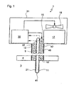
- a device according to the invention for determining the dew point of a gas in a process chamber 3 is shown, which may also be referred to as a dew point sensor 1 or as a condensation sensor.
- the dew point sensor 1 is located with a partial area in a process space 3. Another partial area is located on the other side of a wall 4, which closes off the process space 3.
- a gas with a moisture content In the process space 3 is a gas with a moisture content. By determining the dew point of this gas, the moisture content can be determined.
- the central element of the dew point sensor 1 is a thermally highly conductive body 9, which in this embodiment as a heat pipe 10, which also as a heat pipe is designated executed.
- the heat pipe 10 extends with a first section 11 into the process space 3.
- a second section 12 of the heat pipe 10 is located outside of the process space 3.
- the portion of the heat pipe 10, which projects into the process space 3, is provided with an over tube 41.
- This override 41 is coated, for example with nickel and serves to increase the corrosion resistance of the parts of the dew point sensor 1, which are located in the process chamber 3.
- the overtube 41 is hermetically sealed around the first portion 11 of the heat pipe 10, so that the heat pipe 10 has no direct contact with the process gases within the process space 3.
- the overtube 41 is placed in good heat-conducting contact with the heat pipe 10. Between the heat pipe 10 and the overtube 41, a first temperature sensor 21 is mounted. At the end of the second section 12 of the heat pipe 10 is a device for active temperature control 15, which is designed as a Peltier element 16. This Peltier element 16 is in good conductive contact with the heat pipe 10. Between the heat pipe 10 and the Peltier element 16, a second temperature sensor 22 is mounted.
- a heat sink which may also be referred to as a cooling block 17, is likewise located in good thermally conductive contact on the Peltier element 16. This serves to dissipate heat or resulting cold.
- a Peltier element 16 generates a high temperature on one side and a low temperature on the other side. Depending on the control of the Peltier element 16, the heat pipe 10 can be heated or cooled. In order to better dissipate the resulting heat or cold on the back of the Peltier element 16, the cooling block 17 is provided.
- a fan 18 serves to supply the cooling block 17 with fresh air.
- the cooling block 17 may be designed, for example, with cooling ribs.
- the heat pipe 10 extends from the process chamber 3 into a housing 31 of the dew point sensor 1.
- the Peltier element 16, the cooling block 17 and the fan 18 is arranged in the housing 31.
- the area between the process chamber 3 and the housing 31 may be referred to as a sensor shaft 42.
- the sensor shaft 42 itself has an insulation 48 which continues into the wall 4 of the process space 3 can be. It serves to ensure that the heat pipe 10 can not be supplied with energy or released from the heat pipe 10 in the region of the sensor shaft 42.
- a control and evaluation device 30 is arranged in the housing 31 .
- the first temperature sensor 21 which is located in the process space 3 in the region of the tip of the heat pipe 10, connected.
- the second temperature sensor 22 which is arranged between the Peltier element 16 and the rear end of the heat pipe 10, connected to the control and evaluation device 30.
- the control and evaluation device 30 possible to control the fan 18 and the Peltier element 16.
- the evaluation of the data of the two temperature sensors 21, 22 and the control of the fan 18 and the Peltier element 16 takes place. The evaluation of the data determined by the temperature sensors 21, 22 and the control of the Peltier element 16 will be described below with reference to FIG Fig. 5 described.
- the dew point sensor 1 may additionally be equipped with a display, a keyboard, an interface as well as digital and analog outputs such as limit switch contacts or parts thereof. For clarity, these additional features are not shown in the figures.
- a further embodiment of the dew point sensor 2 according to the invention is shown. This is analogous to that in Fig. 1 constructed dew point sensor 1 described.
- a protective tube 44 is additionally provided, which has a filter 45 at its open end 46. The other end is closed with the wall 4.
- the protective tube 44 with the filter 45 serves to prevent or minimize psychrometric effects.
- an additional cooling of the heat pipe 10 may occur.
- the condensation process can be influenced thereby.
- the protective tube 44 the heat pipe 10 is located with the overtube 41 in a flow-calmed area, so that the effects described above can be reduced. This allows a more reliable measurement of the dew point.
- a further embodiment of a dew point sensor 50 is shown.
- This dew point sensor 50 is substantially analogous to that in FIG Fig. 2 shown dew point sensor 2 constructed. He points as well as the dew point sensor 2 a protective tube 44 with a filter 45 on.
- a resistance heater 51 is provided in the dew point sensor 50 in addition to the Peltier element 16.
- the Peltier element 16 has a relatively low efficiency and therefore requires a relatively large amount of energy to heat the heat pipe 10. Therefore, the resistance heater 51 is provided so as to make the dew point sensor 50 more energy efficient.
- the Peltier element 16 is further used for cooling the heat pipe 10.
- the second temperature sensor 22 should preferably be mounted in thermal contact with the heat pipe 10, the Peltier element 16 and the resistance heater 51. But this is not absolutely necessary.
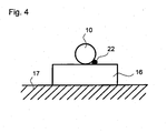
- Fig. 4 is a front view of a second portion of a dew point sensor 1, 2 according to the invention shown.
- the cooling block 17, which is a heat sink the Peltier element 16 is attached.
- the Peltier element 16 On the Peltier element 16, in turn, the heat pipe 10 is provided.
- the second temperature sensor 22 is located in the area adjacent to the heat pipe 10 on the Pelltierelement 16. It is essential here that it is in thermal contact with both the heat pipe 10 and the Peltier element 16. This can be done, for example, with a positioning as in Fig. 4 shown, take place next to the heat pipe 10. But it is also possible to provide the temperature sensor 22 between the Peltier element 16 and the heat pipe 10. In this case, for a better thermal transfer, a thermally conductive substance, for example a heat paste or a thermally conductive adhesive, between the heat pipe 10 and the Peltier element 16 may be provided so that a, preferably good, thermal contact is present.
- a thermally conductive substance for example a heat paste or a thermally conductive
- Fig. 5 is a diagram of the temperature profile of the temperatures detected by the two temperature sensors 21, 22 shown.
- the abscissa indicates the time and the ordinate the temperatures determined.
- the curve K 11 represents the temperatures determined by the sensor 21, which is located at the tip of the heat pipe 10 in the process space 3.
- the curve K 12 in turn represents the temperatures determined by the temperature sensor 22.
- the sensor 22 is located between the heat pipe 10 and Peltier element 16.
- heating of the heat pipe 10 via the Peltier element 16 is started.
- the heating process is stopped.
- the heat pipe 10 is heated at the Peltier element 16, for example, to a temperature of at most about 125 ° C.
- the end of the heat pipe 10 located in the process space 3 follows the rise of the temperature in the heat pipe 10 with a delay.
- the arranged in the process chamber 3 end of the heat pipe 10 does not reach the temperature applied to the Peltier element 16.
- the heating of the heat pipe 10 serves on the one hand to evaporate already lying on the heat pipe 10 condensate. On the other hand, in the method described here, the course of the temperatures during cooling is significantly evaluated.
- the heat pipe 10 is actively cooled via the Peltier element 16.
- a temperature decrease takes place at the tip of the heat pipe 10 in the process space 3.
- a change in the gradient of the slope of the curve K 11 of the temperature takes place.
- the slope substantially corresponds to the straight line g 11 .
- the gradient changes and corresponds substantially to the straight line g 12 .
- the slope of the curve K 11 changes and substantially corresponds to the straight line g 13 .
- the Peltier element 16 is driven such that only a small temperature difference of about 15 ° C between the end of the heat pipe 10, on which the Peltier element 16 is arranged, and the tip, which is located in the process chamber 3, is present.
- FIG. 2 shows a second diagram of the temperature profile of the temperatures measured by the two temperature sensors 21, 22.
- the curve K 21 represents the temperature measured by the temperature sensor 21 and the curve K 22 is the temperature detected by the temperature sensor 22.
- the diagram makes it clear that the dew point can also be determined during heating, or that it can be ascertained during heating, when the area of the heat pipe 10 which is located in the process space 3 is drained.
- the heating of the heat pipe 10 by the Peltier element 16 is started.
- the Peltier element 16 is operated at a constant power up to the point t 25 .
- the curve K 21 of the temperature which is measured by the first temperature sensor 21, a stronger slope or a stronger gradient, as from the time t 22 to t 23 . This is illustrated by the lines g 21 and g 22 .
- the gradient of the curve K 21 increases again. This is illustrated by line g 23 .
- the heating of the heat pipe 10 is terminated and the heat pipe 10 is actively cooled by the Peltier element 16.
- the analysis of the heating process also serves to approximately determine the dew point already during the first heating of the heat pipe 10, so that more precise process parameters can be set during the first cooling and thus a first measurement relative can be done exactly.
- the two diagrams from the Figures 5 and 6 represent the method according to the invention, each with different framework conditions.
- the dew point is in Fig. 5 at about 60 ° C whereas the dew point in Fig. 6 at about 75 ° C is.
- the temporal resolution of the two diagrams is different.
- the dew point temperature can be determined efficiently and reliably.
Landscapes
- Physics & Mathematics (AREA)
- Health & Medical Sciences (AREA)
- Life Sciences & Earth Sciences (AREA)
- Chemical & Material Sciences (AREA)
- Analytical Chemistry (AREA)
- Biochemistry (AREA)
- General Health & Medical Sciences (AREA)
- General Physics & Mathematics (AREA)
- Immunology (AREA)
- Pathology (AREA)
- Investigating Or Analyzing Materials Using Thermal Means (AREA)
Claims (13)
- Dispositif (1) pour déterminer le point de rosée d'un gaz dans un espace de traitement (3)
avec un corps (9) thermoconducteur, en particulier un tube échangeur de chaleur (10),
dans lequel peut être prévue une première section (11) du corps hautement thermoconducteur (9) dans l'espace de traitement (3) et
une deuxième section (12) du corps hautement thermoconducteur (9) en dehors de l'espace de traitement (3),
dans lequel un système destiné à un équilibrage actif de la température (15) en contact thermoconducteur avec le corps hautement thermoconducteur (9) est prévu dans la zone de la deuxième section (12) du corps hautement thermoconducteur (9),
dans lequel un premier capteur de température (21) pour mesurer la température du corps hautement thermoconducteur (9) est prévu dans la zone de la première section (11) du corps hautement thermoconducteur (9)
et
dans lequel un deuxième capteur de température (22) pour mesurer la température du corps hautement thermoconducteur (9) est prévu dans la zone de la deuxième section (12) du corps hautement thermoconducteur (9)
caractérisé en ce que le système destiné à un équilibrage actif de la température (15) est conçu pour un chauffage actif et un refroidissement actif du corps hautement thermoconducteur (9) et en ce qu'est prévu un système de pilotage et d'évaluation (30) destiné à comparer les profils de température des températures mesurées par le premier (11) et le deuxième capteur de température (12) et destiné à déterminer la température du point de rosée à l'aide des discontinuités dans un des profils. - Dispositif selon la revendication 1,
caractérisé en ce que le deuxième capteur de température (22) est disposé dans la zone située entre et/ou en contact thermique avec le système destiné à l'équilibrage actif de température (15) et le corps hautement thermoconducteur (9). - Dispositif selon la revendication 1 ou 2,
caractérisé en ce qu'est prévu un système de pilotage et d'évaluation (30) destiné à comparer les profils de température mesurées par le premier (11) et le deuxième capteur de température (12) et destiné à déterminer la température du point de rosée à l'aide des discontinuités dans un des profils. - Dispositif selon l'une quelconque des revendications 1 à 3,
caractérisé en ce que le système de pilotage et d'évaluation (30) est conçu pour le chauffage et le refroidissement cycliques et/ou réguliers du corps hautement thermoconducteur (9). - Dispositif selon l'une quelconque des revendications 1 à 4,
caractérisé en ce que les systèmes destinés à l'équilibrage actif de température (15) sont réalisés comme un élément Peltier (16). - Dispositif selon l'une quelconque des revendications 1 à 5,
caractérisé en ce que les systèmes destinés à l'équilibrage actif de température (15) comportent un corps de refroidissement (17). - Dispositif selon l'une quelconque des revendications 1 à 6,
caractérisé en ce qu'au moins dans le secteur partiel de la première section (11) du corps hautement thermoconducteur (9) est prévu un tube supérieur (41) et en ce que le premier capteur de température (11) est prévu entre le tube supérieur (41) et le corps hautement thermoconducteur (9). - Dispositif selon l'une quelconque des revendications 1 à 7,
caractérisé en ce que dans l'espace de traitement (3) un tube de protection (44) est prévu autour du corps hautement thermoconducteur (9) ou autour du corps hautement thermoconducteur (9) avec un tube supérieur (41) et en ce que le tube de protection (44) comporte un filtre (45) à une extrémité ouverte (46). - Dispositif selon l'une quelconque des revendications 1 à 8,
caractérisé en ce que le corps hautement thermoconducteur (9) est prévu, passant à travers une paroi (4) laquelle limite l'espace de traitement (3). - Procédé destiné à déterminer le point de rosée d'un gaz dans un espace de traitement (3), en particulier avec un dispositif (1) selon l'une quelconque des revendications 1 à 9,
dans lequel au moyen d'un système destiné à l'équilibrage actif de température (15) un corps hautement thermoconducteur (9) s'étendant à travers une paroi (4) limitant l'espace de traitement (3), en particulier un tube échangeur de chaleur (10), destiné à déterminer le point de rosée, est chauffé et refroidi de manière précise, dans lequel une première température du corps hautement thermoconducteur (9) est déterminée dans l'espace de traitement (3) par un premier capteur de température (21), dans lequel une deuxième température du corps hautement thermoconducteur (9) est déterminée dans la zone du système destiné à l'quilibrage actif de température par un deuxième capteur de température (22), en ce que dans une phase A pendant le refroidissement des discontinuités du profil de température des températures déterminées par le premier (21) et/ou le deuxième capteur de température (22) sont sélectionnées pour définir la température du point de rosée et en ce que dans une phase B le corps hautement thermoconducteur (9) est réchauffé au-dessus de la température du point de rosée à attendre. - Procédé selon la revendication 10,
caractérisé en ce que dans une phase C après détermination de la température du point de rosée, le système destiné à l'équilibrage actif de température (15) est réglé pour obtenir au deuxième capteur de température (22) une température qui se situe dans la gamme de températures du point de rosée, en particulier du point de rosée ± 15 °C. - Procédé selon la revendication 10 ou 11,
caractérisé en ce que les phases B, A, C sont à nouveau exécutées dans cet ordre de façon cyclique ou en cas de besoin. - Procédé selon l'une quelconque des revendications 10 à 12,
caractérisé en ce qu'en cas d'exécution renouvelée de la phase B, le corps hautement thermoconducteur (9) est plus faiblement chauffé que lors de la première exécution de la phase B, en ce qu'un assèchement du corps hautement thermoconducteur (9) est constaté dans l'espace de traitement (3) par des discontinuités du profil de température des températures déterminées par le premier (21) et/ou le deuxième capteur de température (22) et en ce que le réchauffement est terminé après constatation de l'assèchement du corps hautement thermoconducteur (9).
Applications Claiming Priority (1)
| Application Number | Priority Date | Filing Date | Title |
|---|---|---|---|
| PCT/EP2010/001554 WO2011110197A1 (fr) | 2010-03-11 | 2010-03-11 | Dispositif et procédé pour la détermination du point de rosée d'un gaz |
Publications (2)
| Publication Number | Publication Date |
|---|---|
| EP2467705A1 EP2467705A1 (fr) | 2012-06-27 |
| EP2467705B1 true EP2467705B1 (fr) | 2014-12-03 |
Family
ID=42629645
Family Applications (1)
| Application Number | Title | Priority Date | Filing Date |
|---|---|---|---|
| EP10712323.4A Not-in-force EP2467705B1 (fr) | 2010-03-11 | 2010-03-11 | Dispositif et procédé pour la détermination du point de rosée d'un gaz |
Country Status (2)
| Country | Link |
|---|---|
| EP (1) | EP2467705B1 (fr) |
| WO (1) | WO2011110197A1 (fr) |
Families Citing this family (2)
| Publication number | Priority date | Publication date | Assignee | Title |
|---|---|---|---|---|
| US10481078B2 (en) * | 2012-04-16 | 2019-11-19 | Espec Corp. | Hygrometer and temperature-humidity chamber provided with same |
| EP3413039B1 (fr) | 2017-06-07 | 2020-12-23 | Belimed AG | Dispositif de détermination du point de rosée d'un gaz dans une chambre de processus et dispositif de traitement thermique comprenant un tel dispositif de détermination du point de rosée |
Family Cites Families (6)
| Publication number | Priority date | Publication date | Assignee | Title |
|---|---|---|---|---|
| DE1234411B (de) | 1964-07-17 | 1967-02-16 | Siemens Ag | Verfahren zum Bestimmen der Kondensationstemperatur von Daempfen in Gasen |
| DE2634274A1 (de) * | 1976-07-30 | 1978-02-02 | Detlef Mann | Taupunkt-messgeraet |
| GB8701616D0 (en) | 1987-01-26 | 1987-03-04 | Michell Instr Ltd | Dewpoint meter |
| GB2207514A (en) | 1987-06-12 | 1989-02-01 | Flour Milling & Baking Res | Apparatus for measuring atmospheric humidity in ovens |
| IT1258073B (it) | 1992-04-29 | 1996-02-20 | Zanussi Elettromecc | Dispositivo di misura dell'umidita' per forni, in particolare forni dicottura di alimenti |
| DE102005048756A1 (de) | 2005-10-10 | 2007-04-12 | Vereta Gmbh | Vorrichtung zur Messung der Kondensationstemperatur eines Gases |
-
2010
- 2010-03-11 EP EP10712323.4A patent/EP2467705B1/fr not_active Not-in-force
- 2010-03-11 WO PCT/EP2010/001554 patent/WO2011110197A1/fr not_active Ceased
Also Published As
| Publication number | Publication date |
|---|---|
| EP2467705A1 (fr) | 2012-06-27 |
| WO2011110197A1 (fr) | 2011-09-15 |
Similar Documents
| Publication | Publication Date | Title |
|---|---|---|
| EP2341996B1 (fr) | Evaporateur rotatif | |
| DE102013013665B4 (de) | Laboratoriumsbrutschrank mit verbesserter Feuchtigkeitseinstellung | |
| DE102017104508B3 (de) | Verfahren zur Befeuchtung eines Inkubators und Inkubator | |
| DE69313507T2 (de) | Vorrichtung zur Messung der Feuchtigkeit, insbesondere in Nahrungsmittelöfen | |
| EP3431891A1 (fr) | Humidificateur et procédé de conditionnement d'air | |
| EP3048296A1 (fr) | Procede de degivrage d'une pale de rotor d'une eolienne | |
| DE102012216397A1 (de) | Kondensationstrockner mit Ermittlung der Beladung sowie Verfahren zu seinem Betrieb | |
| WO2012020074A1 (fr) | Procédé et dispositif pour déterminer la conductivité thermique et la conductibilité thermique d'un échantillon de mesure | |
| EP3809116B1 (fr) | Chambre d'essai et procédé de conditionnement de l'air | |
| EP3964761A1 (fr) | Procédé de dégivrage d'un composant exposé à l'air ambiant et dispositifs de mise en uvre du procédé | |
| WO2011110197A1 (fr) | Dispositif et procédé pour la détermination du point de rosée d'un gaz | |
| DE19803711A1 (de) | Destillationsanlage und -verfahren | |
| EP4212786A1 (fr) | Procédé de dégivrage d'une grille d'entrée d'air d'un évaporateur d'une pompe à chaleur à air, dispositif pour la mise en oeuvre du procédé et produit programme informatique | |
| DE102012208994A1 (de) | Vorrichtung zum Regeln der Raumtemperatur | |
| DE4204771B4 (de) | Verfahren und Anordnung zum Betrieb eines dampfbeheizten Trockners | |
| DE102015016246A1 (de) | Verfahren und Vorrichtung zum Messen eines Fluidvolumenstroms einer Haustechnikanlage | |
| DE1604292A1 (de) | Vorrichtung zur Regulierung der Feuchte in einer Klimakammer und Verfahren zu ihrem Betrieb | |
| EP4163556B1 (fr) | Procédé et dispositif pour empêcher la formation de glace dans un bac pour collecter le condensat d'un évaporateur d'une pompe à chaleur | |
| EP1938092B1 (fr) | Dispositif destine a mesurer la temperature de condensation d'un gaz | |
| DE102006016956A1 (de) | Vorrichtung zum Bestimmen thermischer Größen in einem Gargerät | |
| DE102023116363B4 (de) | Verfahren zur Bestimmung eines Siedepunkts eines flüssigen Stoffgemischs sowie Rotationsverdampfer mit einem Strömungssensor | |
| DE102008046472A1 (de) | Verfahren und Vorrichtung zur Erzeugung von Feuchtklimaten | |
| DE102021105123B3 (de) | Verfahren zum Betrieb eines Gargeräts sowie Gargerät | |
| EP4177561B1 (fr) | Échangeur de chaleur, pompe à chaleur et procédé de sécurisation forestière d'un échangeur de chaleur | |
| DE19911293C2 (de) | Verfahren und Vorrichtung zur Messung der Taupunkttemperatur |
Legal Events
| Date | Code | Title | Description |
|---|---|---|---|
| PUAI | Public reference made under article 153(3) epc to a published international application that has entered the european phase |
Free format text: ORIGINAL CODE: 0009012 |
|
| 17P | Request for examination filed |
Effective date: 20120301 |
|
| AK | Designated contracting states |
Kind code of ref document: A1 Designated state(s): AT BE BG CH CY CZ DE DK EE ES FI FR GB GR HR HU IE IS IT LI LT LU LV MC MK MT NL NO PL PT RO SE SI SK SM TR |
|
| 17Q | First examination report despatched |
Effective date: 20130412 |
|
| DAX | Request for extension of the european patent (deleted) | ||
| GRAP | Despatch of communication of intention to grant a patent |
Free format text: ORIGINAL CODE: EPIDOSNIGR1 |
|
| INTG | Intention to grant announced |
Effective date: 20140626 |
|
| RAP1 | Party data changed (applicant data changed or rights of an application transferred) |
Owner name: BARTEC BENKE GMBH |
|
| GRAS | Grant fee paid |
Free format text: ORIGINAL CODE: EPIDOSNIGR3 |
|
| GRAA | (expected) grant |
Free format text: ORIGINAL CODE: 0009210 |
|
| AK | Designated contracting states |
Kind code of ref document: B1 Designated state(s): AT BE BG CH CY CZ DE DK EE ES FI FR GB GR HR HU IE IS IT LI LT LU LV MC MK MT NL NO PL PT RO SE SI SK SM TR |
|
| REG | Reference to a national code |
Ref country code: GB Ref legal event code: FG4D Free format text: NOT ENGLISH |
|
| REG | Reference to a national code |
Ref country code: CH Ref legal event code: EP Ref country code: AT Ref legal event code: REF Ref document number: 699644 Country of ref document: AT Kind code of ref document: T Effective date: 20141215 |
|
| REG | Reference to a national code |
Ref country code: IE Ref legal event code: FG4D Free format text: LANGUAGE OF EP DOCUMENT: GERMAN |
|
| REG | Reference to a national code |
Ref country code: DE Ref legal event code: R096 Ref document number: 502010008398 Country of ref document: DE Effective date: 20150115 |
|
| REG | Reference to a national code |
Ref country code: NL Ref legal event code: T3 |
|
| PG25 | Lapsed in a contracting state [announced via postgrant information from national office to epo] |
Ref country code: ES Free format text: LAPSE BECAUSE OF FAILURE TO SUBMIT A TRANSLATION OF THE DESCRIPTION OR TO PAY THE FEE WITHIN THE PRESCRIBED TIME-LIMIT Effective date: 20141203 Ref country code: FI Free format text: LAPSE BECAUSE OF FAILURE TO SUBMIT A TRANSLATION OF THE DESCRIPTION OR TO PAY THE FEE WITHIN THE PRESCRIBED TIME-LIMIT Effective date: 20141203 Ref country code: LT Free format text: LAPSE BECAUSE OF FAILURE TO SUBMIT A TRANSLATION OF THE DESCRIPTION OR TO PAY THE FEE WITHIN THE PRESCRIBED TIME-LIMIT Effective date: 20141203 Ref country code: NO Free format text: LAPSE BECAUSE OF FAILURE TO SUBMIT A TRANSLATION OF THE DESCRIPTION OR TO PAY THE FEE WITHIN THE PRESCRIBED TIME-LIMIT Effective date: 20150303 |
|
| REG | Reference to a national code |
Ref country code: LT Ref legal event code: MG4D |
|
| PG25 | Lapsed in a contracting state [announced via postgrant information from national office to epo] |
Ref country code: GR Free format text: LAPSE BECAUSE OF FAILURE TO SUBMIT A TRANSLATION OF THE DESCRIPTION OR TO PAY THE FEE WITHIN THE PRESCRIBED TIME-LIMIT Effective date: 20150304 Ref country code: SE Free format text: LAPSE BECAUSE OF FAILURE TO SUBMIT A TRANSLATION OF THE DESCRIPTION OR TO PAY THE FEE WITHIN THE PRESCRIBED TIME-LIMIT Effective date: 20141203 Ref country code: CY Free format text: LAPSE BECAUSE OF FAILURE TO SUBMIT A TRANSLATION OF THE DESCRIPTION OR TO PAY THE FEE WITHIN THE PRESCRIBED TIME-LIMIT Effective date: 20141203 Ref country code: LV Free format text: LAPSE BECAUSE OF FAILURE TO SUBMIT A TRANSLATION OF THE DESCRIPTION OR TO PAY THE FEE WITHIN THE PRESCRIBED TIME-LIMIT Effective date: 20141203 Ref country code: HR Free format text: LAPSE BECAUSE OF FAILURE TO SUBMIT A TRANSLATION OF THE DESCRIPTION OR TO PAY THE FEE WITHIN THE PRESCRIBED TIME-LIMIT Effective date: 20141203 |
|
| PG25 | Lapsed in a contracting state [announced via postgrant information from national office to epo] |
Ref country code: SK Free format text: LAPSE BECAUSE OF FAILURE TO SUBMIT A TRANSLATION OF THE DESCRIPTION OR TO PAY THE FEE WITHIN THE PRESCRIBED TIME-LIMIT Effective date: 20141203 Ref country code: CZ Free format text: LAPSE BECAUSE OF FAILURE TO SUBMIT A TRANSLATION OF THE DESCRIPTION OR TO PAY THE FEE WITHIN THE PRESCRIBED TIME-LIMIT Effective date: 20141203 Ref country code: RO Free format text: LAPSE BECAUSE OF FAILURE TO SUBMIT A TRANSLATION OF THE DESCRIPTION OR TO PAY THE FEE WITHIN THE PRESCRIBED TIME-LIMIT Effective date: 20141203 Ref country code: PT Free format text: LAPSE BECAUSE OF FAILURE TO SUBMIT A TRANSLATION OF THE DESCRIPTION OR TO PAY THE FEE WITHIN THE PRESCRIBED TIME-LIMIT Effective date: 20150403 Ref country code: EE Free format text: LAPSE BECAUSE OF FAILURE TO SUBMIT A TRANSLATION OF THE DESCRIPTION OR TO PAY THE FEE WITHIN THE PRESCRIBED TIME-LIMIT Effective date: 20141203 |
|
| PG25 | Lapsed in a contracting state [announced via postgrant information from national office to epo] |
Ref country code: IS Free format text: LAPSE BECAUSE OF FAILURE TO SUBMIT A TRANSLATION OF THE DESCRIPTION OR TO PAY THE FEE WITHIN THE PRESCRIBED TIME-LIMIT Effective date: 20150403 Ref country code: PL Free format text: LAPSE BECAUSE OF FAILURE TO SUBMIT A TRANSLATION OF THE DESCRIPTION OR TO PAY THE FEE WITHIN THE PRESCRIBED TIME-LIMIT Effective date: 20141203 |
|
| REG | Reference to a national code |
Ref country code: DE Ref legal event code: R097 Ref document number: 502010008398 Country of ref document: DE |
|
| PLBE | No opposition filed within time limit |
Free format text: ORIGINAL CODE: 0009261 |
|
| STAA | Information on the status of an ep patent application or granted ep patent |
Free format text: STATUS: NO OPPOSITION FILED WITHIN TIME LIMIT |
|
| PG25 | Lapsed in a contracting state [announced via postgrant information from national office to epo] |
Ref country code: MC Free format text: LAPSE BECAUSE OF FAILURE TO SUBMIT A TRANSLATION OF THE DESCRIPTION OR TO PAY THE FEE WITHIN THE PRESCRIBED TIME-LIMIT Effective date: 20141203 Ref country code: LU Free format text: LAPSE BECAUSE OF FAILURE TO SUBMIT A TRANSLATION OF THE DESCRIPTION OR TO PAY THE FEE WITHIN THE PRESCRIBED TIME-LIMIT Effective date: 20150311 Ref country code: DK Free format text: LAPSE BECAUSE OF FAILURE TO SUBMIT A TRANSLATION OF THE DESCRIPTION OR TO PAY THE FEE WITHIN THE PRESCRIBED TIME-LIMIT Effective date: 20141203 |
|
| REG | Reference to a national code |
Ref country code: CH Ref legal event code: PL |
|
| 26N | No opposition filed |
Effective date: 20150904 |
|
| REG | Reference to a national code |
Ref country code: FR Ref legal event code: ST Effective date: 20151130 |
|
| REG | Reference to a national code |
Ref country code: IE Ref legal event code: MM4A |
|
| PG25 | Lapsed in a contracting state [announced via postgrant information from national office to epo] |
Ref country code: CH Free format text: LAPSE BECAUSE OF NON-PAYMENT OF DUE FEES Effective date: 20150331 Ref country code: IE Free format text: LAPSE BECAUSE OF NON-PAYMENT OF DUE FEES Effective date: 20150311 Ref country code: LI Free format text: LAPSE BECAUSE OF NON-PAYMENT OF DUE FEES Effective date: 20150331 |
|
| PG25 | Lapsed in a contracting state [announced via postgrant information from national office to epo] |
Ref country code: SI Free format text: LAPSE BECAUSE OF FAILURE TO SUBMIT A TRANSLATION OF THE DESCRIPTION OR TO PAY THE FEE WITHIN THE PRESCRIBED TIME-LIMIT Effective date: 20141203 Ref country code: FR Free format text: LAPSE BECAUSE OF NON-PAYMENT OF DUE FEES Effective date: 20150331 |
|
| REG | Reference to a national code |
Ref country code: AT Ref legal event code: MM01 Ref document number: 699644 Country of ref document: AT Kind code of ref document: T Effective date: 20150311 |
|
| PG25 | Lapsed in a contracting state [announced via postgrant information from national office to epo] |
Ref country code: AT Free format text: LAPSE BECAUSE OF NON-PAYMENT OF DUE FEES Effective date: 20150311 |
|
| PG25 | Lapsed in a contracting state [announced via postgrant information from national office to epo] |
Ref country code: MT Free format text: LAPSE BECAUSE OF FAILURE TO SUBMIT A TRANSLATION OF THE DESCRIPTION OR TO PAY THE FEE WITHIN THE PRESCRIBED TIME-LIMIT Effective date: 20141203 |
|
| PG25 | Lapsed in a contracting state [announced via postgrant information from national office to epo] |
Ref country code: BG Free format text: LAPSE BECAUSE OF FAILURE TO SUBMIT A TRANSLATION OF THE DESCRIPTION OR TO PAY THE FEE WITHIN THE PRESCRIBED TIME-LIMIT Effective date: 20141203 Ref country code: HU Free format text: LAPSE BECAUSE OF FAILURE TO SUBMIT A TRANSLATION OF THE DESCRIPTION OR TO PAY THE FEE WITHIN THE PRESCRIBED TIME-LIMIT; INVALID AB INITIO Effective date: 20100311 Ref country code: SM Free format text: LAPSE BECAUSE OF FAILURE TO SUBMIT A TRANSLATION OF THE DESCRIPTION OR TO PAY THE FEE WITHIN THE PRESCRIBED TIME-LIMIT Effective date: 20141203 |
|
| PG25 | Lapsed in a contracting state [announced via postgrant information from national office to epo] |
Ref country code: BE Free format text: LAPSE BECAUSE OF NON-PAYMENT OF DUE FEES Effective date: 20150331 |
|
| PG25 | Lapsed in a contracting state [announced via postgrant information from national office to epo] |
Ref country code: TR Free format text: LAPSE BECAUSE OF FAILURE TO SUBMIT A TRANSLATION OF THE DESCRIPTION OR TO PAY THE FEE WITHIN THE PRESCRIBED TIME-LIMIT Effective date: 20141203 |
|
| PG25 | Lapsed in a contracting state [announced via postgrant information from national office to epo] |
Ref country code: MK Free format text: LAPSE BECAUSE OF FAILURE TO SUBMIT A TRANSLATION OF THE DESCRIPTION OR TO PAY THE FEE WITHIN THE PRESCRIBED TIME-LIMIT Effective date: 20141203 |
|
| P01 | Opt-out of the competence of the unified patent court (upc) registered |
Effective date: 20230726 |
|
| PGFP | Annual fee paid to national office [announced via postgrant information from national office to epo] |
Ref country code: NL Payment date: 20240315 Year of fee payment: 15 |
|
| PGFP | Annual fee paid to national office [announced via postgrant information from national office to epo] |
Ref country code: GB Payment date: 20240307 Year of fee payment: 15 |
|
| PGFP | Annual fee paid to national office [announced via postgrant information from national office to epo] |
Ref country code: IT Payment date: 20240320 Year of fee payment: 15 |
|
| PGFP | Annual fee paid to national office [announced via postgrant information from national office to epo] |
Ref country code: DE Payment date: 20240528 Year of fee payment: 15 |
|
| REG | Reference to a national code |
Ref country code: DE Ref legal event code: R119 Ref document number: 502010008398 Country of ref document: DE |
|
| REG | Reference to a national code |
Ref country code: NL Ref legal event code: MM Effective date: 20250401 |
|
| GBPC | Gb: european patent ceased through non-payment of renewal fee |
Effective date: 20250311 |
|
| PG25 | Lapsed in a contracting state [announced via postgrant information from national office to epo] |
Ref country code: NL Free format text: LAPSE BECAUSE OF NON-PAYMENT OF DUE FEES Effective date: 20250401 |
|
| PG25 | Lapsed in a contracting state [announced via postgrant information from national office to epo] |
Ref country code: DE Free format text: LAPSE BECAUSE OF NON-PAYMENT OF DUE FEES Effective date: 20251001 |
|
| PG25 | Lapsed in a contracting state [announced via postgrant information from national office to epo] |
Ref country code: GB Free format text: LAPSE BECAUSE OF NON-PAYMENT OF DUE FEES Effective date: 20250311 |
|
| PG25 | Lapsed in a contracting state [announced via postgrant information from national office to epo] |
Ref country code: IT Free format text: LAPSE BECAUSE OF NON-PAYMENT OF DUE FEES Effective date: 20250311 |