EP2467504B1 - A method and computer program for forming an object - Google Patents
A method and computer program for forming an object Download PDFInfo
- Publication number
- EP2467504B1 EP2467504B1 EP10745599.0A EP10745599A EP2467504B1 EP 2467504 B1 EP2467504 B1 EP 2467504B1 EP 10745599 A EP10745599 A EP 10745599A EP 2467504 B1 EP2467504 B1 EP 2467504B1
- Authority
- EP
- European Patent Office
- Prior art keywords
- temperature
- molten
- molten alloy
- alloy
- heating
- Prior art date
- Legal status (The legal status is an assumption and is not a legal conclusion. Google has not performed a legal analysis and makes no representation as to the accuracy of the status listed.)
- Not-in-force
Links
Images
Classifications
-
- C—CHEMISTRY; METALLURGY
- C22—METALLURGY; FERROUS OR NON-FERROUS ALLOYS; TREATMENT OF ALLOYS OR NON-FERROUS METALS
- C22C—ALLOYS
- C22C1/00—Making non-ferrous alloys
- C22C1/04—Making non-ferrous alloys by powder metallurgy
- C22C1/0408—Light metal alloys
- C22C1/0416—Aluminium-based alloys
-
- B—PERFORMING OPERATIONS; TRANSPORTING
- B22—CASTING; POWDER METALLURGY
- B22F—WORKING METALLIC POWDER; MANUFACTURE OF ARTICLES FROM METALLIC POWDER; MAKING METALLIC POWDER; APPARATUS OR DEVICES SPECIALLY ADAPTED FOR METALLIC POWDER
- B22F10/00—Additive manufacturing of workpieces or articles from metallic powder
- B22F10/20—Direct sintering or melting
- B22F10/25—Direct deposition of metal particles, e.g. direct metal deposition [DMD] or laser engineered net shaping [LENS]
-
- B—PERFORMING OPERATIONS; TRANSPORTING
- B22—CASTING; POWDER METALLURGY
- B22F—WORKING METALLIC POWDER; MANUFACTURE OF ARTICLES FROM METALLIC POWDER; MAKING METALLIC POWDER; APPARATUS OR DEVICES SPECIALLY ADAPTED FOR METALLIC POWDER
- B22F10/00—Additive manufacturing of workpieces or articles from metallic powder
- B22F10/30—Process control
- B22F10/36—Process control of energy beam parameters
- B22F10/368—Temperature or temperature gradient, e.g. temperature of the melt pool
-
- B—PERFORMING OPERATIONS; TRANSPORTING
- B22—CASTING; POWDER METALLURGY
- B22F—WORKING METALLIC POWDER; MANUFACTURE OF ARTICLES FROM METALLIC POWDER; MAKING METALLIC POWDER; APPARATUS OR DEVICES SPECIALLY ADAPTED FOR METALLIC POWDER
- B22F12/00—Apparatus or devices specially adapted for additive manufacturing; Auxiliary means for additive manufacturing; Combinations of additive manufacturing apparatus or devices with other processing apparatus or devices
- B22F12/10—Auxiliary heating means
- B22F12/13—Auxiliary heating means to preheat the material
-
- B—PERFORMING OPERATIONS; TRANSPORTING
- B22—CASTING; POWDER METALLURGY
- B22F—WORKING METALLIC POWDER; MANUFACTURE OF ARTICLES FROM METALLIC POWDER; MAKING METALLIC POWDER; APPARATUS OR DEVICES SPECIALLY ADAPTED FOR METALLIC POWDER
- B22F12/00—Apparatus or devices specially adapted for additive manufacturing; Auxiliary means for additive manufacturing; Combinations of additive manufacturing apparatus or devices with other processing apparatus or devices
- B22F12/50—Means for feeding of material, e.g. heads
-
- C—CHEMISTRY; METALLURGY
- C22—METALLURGY; FERROUS OR NON-FERROUS ALLOYS; TREATMENT OF ALLOYS OR NON-FERROUS METALS
- C22C—ALLOYS
- C22C1/00—Making non-ferrous alloys
- C22C1/04—Making non-ferrous alloys by powder metallurgy
- C22C1/0483—Alloys based on the low melting point metals Zn, Pb, Sn, Cd, In or Ga
-
- C—CHEMISTRY; METALLURGY
- C22—METALLURGY; FERROUS OR NON-FERROUS ALLOYS; TREATMENT OF ALLOYS OR NON-FERROUS METALS
- C22C—ALLOYS
- C22C12/00—Alloys based on antimony or bismuth
-
- C—CHEMISTRY; METALLURGY
- C22—METALLURGY; FERROUS OR NON-FERROUS ALLOYS; TREATMENT OF ALLOYS OR NON-FERROUS METALS
- C22C—ALLOYS
- C22C21/00—Alloys based on aluminium
- C22C21/06—Alloys based on aluminium with magnesium as the next major constituent
-
- C—CHEMISTRY; METALLURGY
- C22—METALLURGY; FERROUS OR NON-FERROUS ALLOYS; TREATMENT OF ALLOYS OR NON-FERROUS METALS
- C22C—ALLOYS
- C22C23/00—Alloys based on magnesium
- C22C23/02—Alloys based on magnesium with aluminium as the next major constituent
-
- C—CHEMISTRY; METALLURGY
- C30—CRYSTAL GROWTH
- C30B—SINGLE-CRYSTAL GROWTH; UNIDIRECTIONAL SOLIDIFICATION OF EUTECTIC MATERIAL OR UNIDIRECTIONAL DEMIXING OF EUTECTOID MATERIAL; REFINING BY ZONE-MELTING OF MATERIAL; PRODUCTION OF A HOMOGENEOUS POLYCRYSTALLINE MATERIAL WITH DEFINED STRUCTURE; SINGLE CRYSTALS OR HOMOGENEOUS POLYCRYSTALLINE MATERIAL WITH DEFINED STRUCTURE; AFTER-TREATMENT OF SINGLE CRYSTALS OR A HOMOGENEOUS POLYCRYSTALLINE MATERIAL WITH DEFINED STRUCTURE; APPARATUS THEREFOR
- C30B21/00—Unidirectional solidification of eutectic materials
- C30B21/02—Unidirectional solidification of eutectic materials by normal casting or gradient freezing
-
- C—CHEMISTRY; METALLURGY
- C30—CRYSTAL GROWTH
- C30B—SINGLE-CRYSTAL GROWTH; UNIDIRECTIONAL SOLIDIFICATION OF EUTECTIC MATERIAL OR UNIDIRECTIONAL DEMIXING OF EUTECTOID MATERIAL; REFINING BY ZONE-MELTING OF MATERIAL; PRODUCTION OF A HOMOGENEOUS POLYCRYSTALLINE MATERIAL WITH DEFINED STRUCTURE; SINGLE CRYSTALS OR HOMOGENEOUS POLYCRYSTALLINE MATERIAL WITH DEFINED STRUCTURE; AFTER-TREATMENT OF SINGLE CRYSTALS OR A HOMOGENEOUS POLYCRYSTALLINE MATERIAL WITH DEFINED STRUCTURE; APPARATUS THEREFOR
- C30B29/00—Single crystals or homogeneous polycrystalline material with defined structure characterised by the material or by their shape
- C30B29/10—Inorganic compounds or compositions
- C30B29/52—Alloys
-
- B—PERFORMING OPERATIONS; TRANSPORTING
- B22—CASTING; POWDER METALLURGY
- B22F—WORKING METALLIC POWDER; MANUFACTURE OF ARTICLES FROM METALLIC POWDER; MAKING METALLIC POWDER; APPARATUS OR DEVICES SPECIALLY ADAPTED FOR METALLIC POWDER
- B22F10/00—Additive manufacturing of workpieces or articles from metallic powder
- B22F10/30—Process control
- B22F10/38—Process control to achieve specific product aspects, e.g. surface smoothness, density, porosity or hollow structures
-
- B—PERFORMING OPERATIONS; TRANSPORTING
- B22—CASTING; POWDER METALLURGY
- B22F—WORKING METALLIC POWDER; MANUFACTURE OF ARTICLES FROM METALLIC POWDER; MAKING METALLIC POWDER; APPARATUS OR DEVICES SPECIALLY ADAPTED FOR METALLIC POWDER
- B22F12/00—Apparatus or devices specially adapted for additive manufacturing; Auxiliary means for additive manufacturing; Combinations of additive manufacturing apparatus or devices with other processing apparatus or devices
- B22F12/10—Auxiliary heating means
- B22F12/17—Auxiliary heating means to heat the build chamber or platform
-
- B—PERFORMING OPERATIONS; TRANSPORTING
- B22—CASTING; POWDER METALLURGY
- B22F—WORKING METALLIC POWDER; MANUFACTURE OF ARTICLES FROM METALLIC POWDER; MAKING METALLIC POWDER; APPARATUS OR DEVICES SPECIALLY ADAPTED FOR METALLIC POWDER
- B22F12/00—Apparatus or devices specially adapted for additive manufacturing; Auxiliary means for additive manufacturing; Combinations of additive manufacturing apparatus or devices with other processing apparatus or devices
- B22F12/90—Means for process control, e.g. cameras or sensors
-
- B—PERFORMING OPERATIONS; TRANSPORTING
- B22—CASTING; POWDER METALLURGY
- B22F—WORKING METALLIC POWDER; MANUFACTURE OF ARTICLES FROM METALLIC POWDER; MAKING METALLIC POWDER; APPARATUS OR DEVICES SPECIALLY ADAPTED FOR METALLIC POWDER
- B22F2999/00—Aspects linked to processes or compositions used in powder metallurgy
-
- Y—GENERAL TAGGING OF NEW TECHNOLOGICAL DEVELOPMENTS; GENERAL TAGGING OF CROSS-SECTIONAL TECHNOLOGIES SPANNING OVER SEVERAL SECTIONS OF THE IPC; TECHNICAL SUBJECTS COVERED BY FORMER USPC CROSS-REFERENCE ART COLLECTIONS [XRACs] AND DIGESTS
- Y02—TECHNOLOGIES OR APPLICATIONS FOR MITIGATION OR ADAPTATION AGAINST CLIMATE CHANGE
- Y02P—CLIMATE CHANGE MITIGATION TECHNOLOGIES IN THE PRODUCTION OR PROCESSING OF GOODS
- Y02P10/00—Technologies related to metal processing
- Y02P10/25—Process efficiency
Definitions
- Embodiments of the present invention relate to a method, apparatus, computer readable storage medium and computer program for forming an object.
- Solid Freeform Fabrication is a group of manufacturing technologies that are capable of producing 3D solid parts by a consecutive layer-wise shaping and consolidation of material (e.g. in the form of powder). Part geometric data can be taken directly from a Computer Aided Design (CAD) model and processed to form an object without the need for any moulds or tools. Various materials and combinations of materials such as plastics, waxes, metals and ceramics can be processed according to the process used.
- CAD Computer Aided Design
- US4450136 describes a substantially homogeneous calcium/aluminum alloy having calcium/aluminum atomic ratio of from about 60/40 to 80/20.
- US6273969 describes an alloy comprising a first element A, a second element B, a third element C, and a fourth element D.
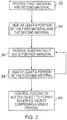
- a method for forming an object comprising: providing first substantially solid material comprising at least a first material having a first melting temperature and a second material having a second melting temperature; heating a portion of the first substantially solid material to form a first portion of substantially molten alloy, the molten alloy having a third solidifying temperature less than the first temperature and the second temperature; cooling said portion below said first and second temperatures; retaining in a molten state said position of molten alloy at a temperature below said first and second temperatures within confines defined by a remaining portion of said first solid material; providing further substantially solid material to at least a portion of the molten alloy, the further material melting at a fourth melting temperature; heating at least a portion of said further material to form a further portion of substantially molten alloy at least partially in contact with said first portion of molten alloy; cooling said further portion without solidification to a temperature less than said fourth temperature; retaining in a molten state said further portion of molten
- the substantially molten alloy has a temperature above which the alloyed material does not substantially warp.
- the method may further comprise repeating the steps of providing further material, heating the further material, cooling the further material and retaining the further material in a molten state to form an object.
- the object may be substantially molten and the method may further comprise controlling cooling of the object to form a solidified object comprising a controlled micro structure. Controlling the cooling of the object may form a solidified object comprising a single crystal.
- the method may further comprise controlling heating of the substantially molten alloy to maintain the temperature of the molten alloy above the solidifying temperature and below the first and second and fourth melting temperatures.
- the method may further comprise detecting the temperature of the molten alloy and controlling the heating of the molten alloy using the detected temperature to maintain the temperature of the molten alloy above the solidifying temperature and below the first and fourth melting temperatures.
- the method may further comprise heating the first material to a temperature below the first temperature prior to providing the first material and/or heating the second material to a temperature below the second temperature prior to providing the second material and/or heating the further material to a temperature below the fourth temperature.
- the first material and the second material may be provided as a layer and the further material may be provided as a layer.
- the layers may be formed by sequential deposition of non mixed materials and/or deposition of mixed materials.
- the first material, the second material and the further material may be provided as a powder.
- the substantially solid further material may comprise at least the first material and the second material.
- the first material and the second material may be provided in proportions that form a eutectic mixture and heating the first and second materials may form a substantially molten eutectic alloy.
- the first material and the second material may be provided in proportion such that heating the first and second materials forms a substantially molten hyper eutectic alloy or a substantially molten hypo eutectic alloy.
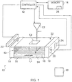
- Figure 1 illustrates apparatus 10 for forming an object, comprising: a depositor 20 comprising a first material having a melting point at a first temperature and a second material having a melting point at a second temperature, the depositor 20 being configured to deposit at least the first material and the second material; a heater 22 configured to heat at least a portion of the first and second materials above the first and second temperatures to form a substantially molten alloy, the molten alloy having a solidifying point at a third temperature, the third temperature being less than the first temperature and the second temperature; and wherein the depositor 20 is configured to provide substantially solid further material to at least a portion of the molten alloy, the further material having a melting point at a temperature greater than the third temperature.
- the implementation of the controller 12 can be in hardware alone (e.g. a circuit, a processor, etc), have certain aspects in software including firmware alone or can be a combination of hardware and software (including firmware).
- the controller 12 may be implemented using instructions that enable hardware functionality, for example, by using executable computer program instructions in a general-purpose or special-purpose processor that may be stored on a computer readable storage medium (disk, memory etc) to be executed by such a processor.
- the controller 12 is configured to read from and write to the memory 14.
- the controller may also comprise an output interface via which data and/or commands are output by the controller 12 and an input interface via which data and/or commands are input to the controller 12.
- the memory 14 may be any suitable memory and may be, for example, permanent built-in memory such as flash memory or it may be a removable memory such as a hard disk, secure digital (SD) card or a micro-drive.
- the memory 14 stores a computer program 28 comprising computer program instructions that control the operation of the apparatus 10 when loaded into the controller 12.
- the computer program instructions 28 provide the logic and routines that enables the apparatus 10 to perform at least some of the steps of the methods illustrated in Figs. 2 and 5 .
- the controller 12 by reading the memory 14 is able to load and execute the computer program 28.
- the computer program may arrive at the apparatus 10 via any suitable delivery mechanism 30.
- the delivery mechanism 30 may be, for example, a computer-readable storage medium, a computer program product, a memory device, a record medium such as a Blue-ray disc, a CD-ROM, a DVD, or any article of manufacture that tangibly embodies the computer program 28.
- the delivery mechanism may be a signal configured to reliably transfer the computer program 28.
- the apparatus 10 may propagate or transmit the computer program 28 as a computer data signal.
- memory 14 is illustrated as a single component it may be implemented as one or more separate components some or all of which may be integrated/removable and/or may provide permanent/semi-permanent/ dynamic/cached storage.
- references to 'computer-readable storage medium', 'computer program product', 'tangibly embodied computer program' etc. or a 'controller', 'computer', 'processor' etc. should be understood to encompass not only computers having different architectures such as single /multi- processor architectures and sequential/parallel architectures but also specialized circuits such as field-programmable gate arrays (FPGA), application specific circuits (ASIC), signal processing devices and other devices.
- References to computer program, instructions, code etc. should be understood to encompass software for a programmable processor or firmware such as, for example, the programmable content of a hardware device whether instructions for a processor, or configuration settings for a fixed-function device, gate array or programmable logic device etc.
- the support 16 has a substantially horizontal planar upper surface for supporting the substrate 18.
- the support 16 may have any suitable shape and may have, for example, a substantially rectangular cross section and a depth.
- the support 16 may comprise any suitable material that remains solid at relatively high temperatures (above seven hundred degrees Celsius for example) and may comprise a ceramic, for example.
- the support 16 may be referred to as a processing table.
- the substrate 18 is supported by the support 16 and is arranged to receive material from the depositor 20.
- the substrate 18 may have a similar shape to the support 16 and may have, for example, a substantially rectangular cross section and a depth.
- the substrate 18 may comprise any suitable material that remains solid at relatively high temperatures (above seven hundred degrees Celsius for example) and may comprise a ceramic, for example.
- the apparatus 10 may not include a substrate 18.
- objects may be formed by first depositing a plurality of (n) layers which are not alloyed/joined and then on layer (n+1), the apparatus 10 commences the method illustrated in fig. 2 and discussed in the following paragraphs.
- the support 16 is coupled to the walls 19 via a mechanism (not illustrated in the figure) that enables the support 16 to move vertically with respect to the walls 19. It should be appreciated from the above description that the support 16, the substrate 18 and the walls 19 form a container in which an object may be formed.
- the depositor 20 comprises a storage member for storing material to be deposited and one or more apertures for allowing stored material to be deposited.
- the controller 12 may be configured to control the movement of the depositor 20 over the substrate 18 so that the depositor 20 may deposit material over at least a portion of the substrate 18.
- the depositor 20 may be manually operated by a user of the apparatus 10.
- the depositor 20 may also be configured to level the surface of deposited material.
- the depositor may comprise a blade that spreads material across the surface.
- the detector 24 is configured to detect the temperature of material deposited on the substrate 18 and provide the detected temperature to the controller 12 for processing.
- the detector 24 may be an electronic thermometer or a thermocouple or a pyrometer or an infra-red thermal imaging camera for example.
- the detector 24 is illustrated as being positioned in one of the walls 19 of the apparatus 10. In other embodiments, the detector 24 may be located elsewhere (e.g. on the substrate 18, or above the material deposited) and in further embodiments, the apparatus 10 may comprise a plurality of detectors 24 that may be located in different positions on the apparatus 10 (e.g. on the walls 19 and on the substrate 18).
- the second heater 26 is configured to provide heat to material deposited on the substrate 18 and may also heat the support 16 and/or the substrate 18 and/or the walls 19.
- the second heater 26 may be any suitable heater for maintaining the temperature of material deposited on the substrate 18 at a desired temperature.
- the controller 12 is configured to process the detected temperature received from the detector 24 and control the second heater 26 using the detected temperature.
- the second heater 26 is illustrated as being positioned in one of the walls 19 of the apparatus 10. In other embodiments, the second heater 26 may be located elsewhere (e.g. on the substrate 18) and in further embodiments, the apparatus 10 may comprise a plurality of second heaters 26 that may be located in different positions on the apparatus 10 (e.g. on the walls 19 and on the substrate 18).
- the second heater 26 may be manually operated by a user of the apparatus 10. The second heater may supply heat by radiation (e.g. using an infra-red heater above the materials deposited).
- the apparatus 10 may not include a second heater 26.
- the material deposited on the substrate 18 may have a relatively low solidifying point temperature and may not require heating.
- the first heater 22 may be configured to provide the same functionality as the second heater 26 (i.e. to provide heat to material deposited on the substrate 18).
- the first heater 22 may provide an electron beam that can be scanned quickly across the deposited material to maintain the temperature of the deposited material without joining/alloying the material.
- the deposited material may be scanned with different speed/power etc to join/alloy deposited material where required
- the apparatus 10 is arranged so that the support 16 is vertically positioned near the top of the walls 19.
- the depositor 20 provides at least a first material and a second material on the substrate 18 and levels the first material and the second material to be substantially flush with the top of the walls 19 (additional material is swept from the apparatus 10 by the depositor 20).
- the apparatus 10 may not include a substrate 18 and may instead deposit a plurality of unalloyed layers of material initially, and then provide the first material and the second material on the plurality of layers.
- the first material is provided by the depositor 20 as a powder and the second material is provided by the depositor 20 as a powder.
- the first material and the second material may be pre-mixed and deposited together.
- the first material and the second material may be deposited sequentially so that the first material is deposited as a first layer and then the second material is deposited on the first layer to form a second layer.
- the first and second materials may in a different form to powder (e.g. bulk or wire form).
- step 32 may include depositing the first and second materials and additionally, third and fourth materials.
- the first and second materials are any materials that may be provided in proportions that form an alloy having a solidifying point temperature that is lower than the melting point temperature of the first material and the melting point temperature of the second material.
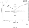
- Fig. 3 illustrates a graph having a horizontal (X) axis 42 for the proportions of the first material (labeled material A in the graph) and the second material (labeled material B in the graph) as a percentage of total alloyed material, a vertical (Y) axis 44 for the temperature of the first and second materials and a trace 46 that represents the solidifying point of the first and second material when they are alloyed in different proportions.
- Figure 3 is essentially a phase diagram and line 46 is effectively the solidus. Temperatures above the line 46 represent material that is substantially liquid while temperatures below line 46 are not substantially liquid and may included states such as semi-liquid or solid.
- the trace 46 commences at a first temperature that corresponds to the melting point/solidifying point of the first material only.
- the trace 46 has a negative gradient as the position along the X axis increases, until a particular material proportion (50% in this example) that forms a minima on the trace 46.
- the trace 46 then has a positive gradient as the position along the X axis increases and ends at a second temperature that corresponds to the melting point/solidifying point of the second material only.
- the trace 46 has a minima (i.e. a lowest melting point/solidifying point of the alloyed first and second materials) at a particular proportion (50% in this example) of the first and second materials.
- This minima is usually referred to as a 'eutectic point' and such a combination of materials is usually referred to as a eutectic alloy.
- the eutectic point has a lower melting point/solidifying point temperature than the melting point temperature of the first material and the melting point temperature of the second material.
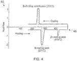
- the first material may be bismuth (ninety seven percent of the overall composition by weight) having a melting point at two hundred and seventy one degrees Celsius and the second material may be zinc (three percent of the overall composition) having a melting point at four hundred and nineteen degrees Celsius.
- Fig. 4 illustrates a schematic indicating the key points on a DSC graph of the melting points of these two materials and the eutectic alloy they subsequently form due to heating above four hundred and nineteen degrees Celsius.
- the schematic graph includes a horizontal (X) axis for temperature and a vertical (Y) axis for Heat Flow. The graph illustrates that upon heating, the bismuth melts at two hundred and seventy one degrees Celsius and that the zinc melts at four hundred and nineteen degrees Celsius. However, upon cooling, the eutectic bismuth-zinc alloy solidifies at two hundred and fifty three degrees Celsius.
- the first material may be aluminum (thirty two point three percent of the composition) having a melting point of six hundred and sixty degrees Celsius and the second material may be magnesium (sixty seven point seven percent of the composition) having a melting point of six hundred and forty nine degrees Celsius.
- the aluminum and magnesium form a eutectic aluminum-magnesium alloy with a solidifying point temperature of four hundred and thirty seven degrees Celsius.
- the solidifying point temperature of the alloyed first and second materials is lower than the melting point temperature of the first material and the melting point temperature of the second material.
- These compositions of the first and second material are usually referred to as hyper eutectic or hypo eutectic depending on whether each material in the composition is more or less than the specific eutectic alloy composition.
- the solidifying point temperature of the alloyed first and second materials is the solidus of the formed alloy.
- an alloy of aluminum (sixty five percent of the composition) and magnesium (thirty five percent of the composition) forms a hypo eutectic alloy with a melting point of four hundred and fifty one degrees Celsius. It should be appreciated that the solidifying point temperature of this hypo eutectic alloy is less than the melting point temperature of both aluminum and magnesium.
- the first material and the second material may be any materials that are provided in proportions that form an alloy having a solidifying point temperature that is lower than the melting point temperature of the first material and the melting point temperature of the second material.
- the controller 12 controls the first heater 22 to provide heat to at least a portion of the first and second materials deposited on the substrate 18.
- the first heater 22 heats the first and second materials above their respective melting point temperatures so that they melt and form a molten alloy.
- the alloy has a lower solidifying point temperature than the melting point temperatures of the first material and the second material.
- step 32 includes providing additional different material (e.g. a third material, a fourth material etc), it should be understood that at least some of the additional different material may have a melting point temperature that is lower than the solidifying point temperature of the alloyed first and second materials.
- the first material may be aluminum
- the second material may be magnesium
- a third material provided in step 32 may be Lithium. Lithium has a melting point temperature of one hundred and eighty degrees Celsius which is lower than the lowest solidifying point temperature (approximately four hundred and fifty degrees Celsius, depending upon the proportions of materials) of the formed aluminum, magnesium, lithium alloy.
- step 32 may have a relatively high melting point temperature and may not melt when heat is provided in step 34.
- the controller 12 controls the depositor 20 to provide substantially solid further material over the substrate 18 and thereby to at least a portion of the molten alloy.
- the support 16 is also moved vertically downwards so that the substantially solid further material is flush with the walls 19 of the apparatus 10.
- the further material has a melting point temperature that is greater than the solidifying point temperature of the molten alloy. Consequently, the substantially solid further material remains a solid when deposited on the substantially molten alloy.
- the substantially molten alloy may be liquid, semi-liquid, partially molten or partially solidified (e.g. the top surface of the molten alloy may form a solidified film).
- the alloyed material should not cool to a temperature below which thermally induced stresses will cause sufficient warpage to cause the object to fail (e.g. for the alloyed material to curl up significantly/disruptively). Consequently, the substantially molten alloy should remain above a temperature at which it may warp significantly/disruptively.
- the further material Prior to being deposited on the molten alloy, the further material may be heated to a temperature that is less than the melting point temperature of the further material. This may provide an advantage in that the addition of the further material to the molten alloy may not substantially cool the molten alloy.
- the further material may comprise the first material and/or the second material and may be a powder.
- the substantially solid further material may comprise different material/materials to the first and second materials and may be in a different form to powder (e.g. bulk or wire form).
- step 36 may include providing additional material(s) which is different to the further material. Where step 36 includes providing more than one material, the deposited material may be pre-mixed and provided in a layer or may be provided sequentially.
- the additional material(s) may have a melting point temperature that is lower than the solidifying point temperature of the molten alloy.
- the additional material(s) may have a relatively high melting point temperature and may remain solid during the formation of an object.
- Steps 36 and 38 are then repeated until a desired object is formed from the heated material.
- steps 32 to 38 may form a plurality of layers 52 of powdered material (usually referred to as a powder bed) and an object 54 on the substrate 18.
- the material surrounding the object 54 that has not been heated and melted remains as a powder.
- the apparatus 10 may additionally include a cooler (e.g. a fan) for cooling and solidifying the object 54. Once cooled and solidified, the object 54 may be removed from the substrate 18 (if attached to the substrate 18) and the remaining material in the plurality of layers 52 may be discarded or saved for forming a further object. In other embodiments, the object 54 may solidify at least in part during steps 32 to 38 and may not require cooling once the final layer of material is deposited.
- a cooler e.g. a fan
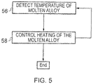
- the controller 12 may receive the detected temperature of the molten alloy during steps 32, 34, 36 and 38 from the detector 24 (step 56).
- the controller may receive detected temperature from the un-molten material.
- the controller 12 may then control the second heater 26 to provide heat to the molten alloy to maintain the temperature of the molten alloy above the solidifying point temperature of the molten alloy but less than the melting point temperature of the further material (step 58). Steps 56 and 58 may be repeated until the object 54 is formed and ready for cooling.
- the controller 12 may control the second heater 26 and the cooler so that the molten object 54 is directionally cooled and solidifies in a controlled direction from one end of the object to the other (e.g. from top to bottom).
- Directional cooling enables control of solidification/re-crystallization front, enables control over formation of grain structure, and control over grain structure may enable formation of desired grain structures (e.g. single crystal structures). Consequently, this form of directional cooling may enable the apparatus 10 to form objects 54 that comprise a single crystal (step 40). Controlled cooling of the part(s) may also allow the formation of other structures that are not single crystals.
- the formation of single crystal metals is known in the art of metallurgy and will consequently not be described in further detail here.
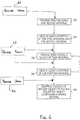
- Fig. 6 illustrates a flow diagram of another method for forming an object according to various embodiments of the present invention.
- the method illustrated in fig. 6 is similar to the method illustrated in fig. 2 and where the steps are the similar, the same reference numerals are used.
- the method illustrated in fig. 6 provides an exemplary embodiment of how an object may be formed having a desired grain structure.
- the method illustrated in fig. 6 differs from the method illustrated in fig. 2 in that the method further comprises providing a seed in contact with the substantially molten object such that the controlled microstructure of the solidifying object or solidified object follows that of the seed.
- the seed is a solid object with a predetermined/known microstructure and may have any suitable shape.
- the seed may be providing in step 60 prior to step 32 and consequently provides a platform onto which the material is attached.
- the seed may be provided to the substantially molten object during manufacture of the substantially molten object (step 62, between steps 34 & 36 or between steps 36 & 38) or after the manufacture of the substantially molten object (step 64, between steps 38 & 40).
- the controlled cooling starts from a single point on the substantially molten object.
- the controlled cooling ensures that solidification of the substantially molten object only emanates from the seed and that solidification does not emanate from points that are not a seed.
- the controlled microstructure of the solidifying object or solidified object follows that of the seeds.
- the controlled cooling starts from a plurality of points on the substantially molten object.
- the controlled cooling ensures that solidification of the substantially molten part only emanates from the plurality of seeds and that solidification does not emanate from points that are not a seed.
- Embodiments of the present invention provide several advantages.
- One such advantage is that since the molten alloy has a lower melting point temperature, the solidification of the object 54 is delayed and a substantial thickness of material may be deposited before the object/partially completed object solidifies. This may help to reduce warping of the material upon solidification and result in the formed object better resembling the model in the CAD file.
- the operation of the detector 24 and the second heater 26 may assist in maintaining the object in a molten form until the object is completed.
- embodiments of the present invention may reduce subsequent post-processing operations such as machining of the object to remove such support structures.
- the blocks illustrated in the Figs. 2 , 5 and 6 may represent steps in a method and/or sections of code in the computer program 28.
- the illustration of a particular order to the blocks does not necessarily imply that there is a required or preferred order for the blocks and the order and arrangement of the block may be varied. Furthermore, it may be possible for some steps to be omitted.
- the first material may be an element (e.g. aluminum) or an alloy.
- the first material may be pure or may contain impurities.
- the second material may be an element (e.g. magnesium) or an alloy.
- the second material may be pure or may contain impurities.
- the further material may be an element (e.g. magnesium), a combination of materials (e.g. aluminum powder and magnesium powder) or an alloy.
- the second material may be pure or may contain impurities.
- the first material, second material and the further material may include metals, polymer, ceramic and/or organic components.
- the apparatus 10 may form a substantially molten object by repeatedly depositing material and heating at least a portion of the material above the melting point of the material.
- the material may comprise any metallic material and may not necessarily comprise a eutectic alloy, a hyper eutectic alloy or a hypo eutectic alloy.
- the apparatus 10 may be configured to control cooling of the molten object (e.g. by using a cooler such as a fan and a further heater as described above) to form a solidified object comprising a desired grain structure (e.g. a single crystal).
- the solidified object may be formed from one or more seeds as described in the preceding paragraphs.
Landscapes
- Chemical & Material Sciences (AREA)
- Engineering & Computer Science (AREA)
- Materials Engineering (AREA)
- Manufacturing & Machinery (AREA)
- Mechanical Engineering (AREA)
- Metallurgy (AREA)
- Organic Chemistry (AREA)
- Crystallography & Structural Chemistry (AREA)
- Automation & Control Theory (AREA)
- Inorganic Chemistry (AREA)
- Crystals, And After-Treatments Of Crystals (AREA)
- Powder Metallurgy (AREA)
- Pressure Welding/Diffusion-Bonding (AREA)
- Materials For Medical Uses (AREA)
- Manufacture Of Alloys Or Alloy Compounds (AREA)
Applications Claiming Priority (3)
| Application Number | Priority Date | Filing Date | Title |
|---|---|---|---|
| US12/583,518 US8186414B2 (en) | 2009-08-21 | 2009-08-21 | Method for forming an object |
| GB0914621A GB2472846A (en) | 2009-08-21 | 2009-08-21 | Solid freeform fabrication |
| PCT/EP2010/062173 WO2011020912A2 (en) | 2009-08-21 | 2010-08-20 | A method, apparatus, computer readable storage medium and computer program for forming an object |
Publications (2)
| Publication Number | Publication Date |
|---|---|
| EP2467504A2 EP2467504A2 (en) | 2012-06-27 |
| EP2467504B1 true EP2467504B1 (en) | 2017-10-04 |
Family
ID=42710632
Family Applications (1)
| Application Number | Title | Priority Date | Filing Date |
|---|---|---|---|
| EP10745599.0A Not-in-force EP2467504B1 (en) | 2009-08-21 | 2010-08-20 | A method and computer program for forming an object |
Country Status (4)
| Country | Link |
|---|---|
| EP (1) | EP2467504B1 (ja) |
| JP (1) | JP2013502324A (ja) |
| CN (1) | CN102549178B (ja) |
| WO (1) | WO2011020912A2 (ja) |
Cited By (1)
| Publication number | Priority date | Publication date | Assignee | Title |
|---|---|---|---|---|
| US10821512B2 (en) | 2017-01-06 | 2020-11-03 | General Electric Company | Systems and methods for controlling microstructure of additively manufactured components |
Families Citing this family (7)
| Publication number | Priority date | Publication date | Assignee | Title |
|---|---|---|---|---|
| WO2014131444A1 (en) * | 2013-02-27 | 2014-09-04 | Slm Solutions Gmbh | Apparatus and method for producing work pieces having a tailored microstructure |
| JP6216881B2 (ja) * | 2013-11-14 | 2017-10-18 | ゼネラル・エレクトリック・カンパニイ | 単結晶合金部品の積層製造 |
| JP6344004B2 (ja) * | 2014-03-28 | 2018-06-20 | 国立大学法人大阪大学 | 単結晶の製造方法 |
| US9999924B2 (en) | 2014-08-22 | 2018-06-19 | Sigma Labs, Inc. | Method and system for monitoring additive manufacturing processes |
| US10443115B2 (en) * | 2015-08-20 | 2019-10-15 | General Electric Company | Apparatus and method for direct writing of single crystal super alloys and metals |
| US20180095450A1 (en) | 2016-09-30 | 2018-04-05 | Velo3D, Inc. | Three-dimensional objects and their formation |
| KR20220031745A (ko) | 2019-07-26 | 2022-03-11 | 벨로3디, 인크. | 3차원 물체 형상화에 대한 품질 보증 |
Citations (1)
| Publication number | Priority date | Publication date | Assignee | Title |
|---|---|---|---|---|
| US6391251B1 (en) * | 1999-07-07 | 2002-05-21 | Optomec Design Company | Forming structures from CAD solid models |
Family Cites Families (6)
| Publication number | Priority date | Publication date | Assignee | Title |
|---|---|---|---|---|
| US4450136A (en) * | 1982-03-09 | 1984-05-22 | Pfizer, Inc. | Calcium/aluminum alloys and process for their preparation |
| US5047113A (en) * | 1989-08-23 | 1991-09-10 | Aleksandar Ostrogorsky | Method for directional solidification of single crystals |
| JPH107496A (ja) * | 1996-06-25 | 1998-01-13 | Hitachi Cable Ltd | 窒化物結晶の製造方法およびその装置 |
| US6273969B1 (en) * | 1998-01-07 | 2001-08-14 | Rensselaer Polytechnic Institute | Alloys and methods for their preparation |
| US6872912B1 (en) * | 2004-07-12 | 2005-03-29 | Chromalloy Gas Turbine Corporation | Welding single crystal articles |
| US8691329B2 (en) * | 2007-01-31 | 2014-04-08 | General Electric Company | Laser net shape manufacturing using an adaptive toolpath deposition method |
-
2010
- 2010-08-20 WO PCT/EP2010/062173 patent/WO2011020912A2/en active Application Filing
- 2010-08-20 CN CN201080037199.5A patent/CN102549178B/zh not_active Expired - Fee Related
- 2010-08-20 JP JP2012525177A patent/JP2013502324A/ja active Pending
- 2010-08-20 EP EP10745599.0A patent/EP2467504B1/en not_active Not-in-force
Patent Citations (1)
| Publication number | Priority date | Publication date | Assignee | Title |
|---|---|---|---|---|
| US6391251B1 (en) * | 1999-07-07 | 2002-05-21 | Optomec Design Company | Forming structures from CAD solid models |
Cited By (1)
| Publication number | Priority date | Publication date | Assignee | Title |
|---|---|---|---|---|
| US10821512B2 (en) | 2017-01-06 | 2020-11-03 | General Electric Company | Systems and methods for controlling microstructure of additively manufactured components |
Also Published As
| Publication number | Publication date |
|---|---|
| CN102549178A (zh) | 2012-07-04 |
| CN102549178B (zh) | 2015-12-02 |
| WO2011020912A2 (en) | 2011-02-24 |
| EP2467504A2 (en) | 2012-06-27 |
| WO2011020912A3 (en) | 2011-05-19 |
| JP2013502324A (ja) | 2013-01-24 |
Similar Documents
| Publication | Publication Date | Title |
|---|---|---|
| US8347940B2 (en) | Method for forming an object | |
| EP2467504B1 (en) | A method and computer program for forming an object | |
| US10239156B2 (en) | Multi-density, multi-property turbine component | |
| EP3096905B1 (en) | A method of additive manufacturing utilizing an epitaxy process | |
| CN107107187B (zh) | 含铍制品的增材制造 | |
| Song et al. | Development of the molten pool and solidification characterization in single bead multilayer direct energy deposition | |
| Mumtaz et al. | A method to eliminate anchors/supports from directly laser melted metal powder bed processes | |
| JP6250056B2 (ja) | 熱シールドを有するシェルモールド | |
| US7784668B2 (en) | Repair method for propagating epitaxial crystalline structures by heating to within 0-100° f of the solidus | |
| US20050112015A1 (en) | Laser sintered titanium alloy and direct metal fabrication method of making the same | |
| US11260453B2 (en) | Method for additive production, component, and apparatus for additive production | |
| Khan et al. | Numerical investigation of heat current study across different platforms in SLM processed multi-layer AlSi10Mg | |
| CA3068408C (en) | An additive manufacturing technique for precipitation-hardened superalloy powdered material | |
| Bimber et al. | Ni-concentration dependence of directed energy deposited NiTi alloy microstructures | |
| CN107405681A (zh) | 用于制造涡轮机部件、坯件以及最终部件的方法 | |
| JP2018115388A (ja) | 金属物質でコーティングされた粒状物質から物体を製造する方法及び関連製品 | |
| JP5943963B2 (ja) | 三次元造形用材料、及び、三次元造形方法 | |
| GB2472846A (en) | Solid freeform fabrication | |
| Kang et al. | Cooling control for castings by adopting skeletal sand mold design | |
| CA3023469C (en) | Pretreatment, method for additive production of a component, and device | |
| JP5527655B2 (ja) | 化合物粒子が傾斜分散した傾斜機能材料の製造方法 | |
| Li et al. | Numerical and experimental investigation of molten metal droplet deposition applied to rapid prototyping | |
| Frederick | Control of grain structure in selective-electron beam melting of nickel-based superalloys | |
| Chowdhury et al. | Effects of Preheating on Thermal Behavior in Inconel 718 Processed by Additive Manufacturing | |
| JP2023031963A (ja) | 立体造形物の製造方法 |
Legal Events
| Date | Code | Title | Description |
|---|---|---|---|
| PUAI | Public reference made under article 153(3) epc to a published international application that has entered the european phase |
Free format text: ORIGINAL CODE: 0009012 |
|
| 17P | Request for examination filed |
Effective date: 20120320 |
|
| AK | Designated contracting states |
Kind code of ref document: A2 Designated state(s): AL AT BE BG CH CY CZ DE DK EE ES FI FR GB GR HR HU IE IS IT LI LT LU LV MC MK MT NL NO PL PT RO SE SI SK SM TR |
|
| DAX | Request for extension of the european patent (deleted) | ||
| 17Q | First examination report despatched |
Effective date: 20130605 |
|
| GRAP | Despatch of communication of intention to grant a patent |
Free format text: ORIGINAL CODE: EPIDOSNIGR1 |
|
| INTG | Intention to grant announced |
Effective date: 20170313 |
|
| GRAS | Grant fee paid |
Free format text: ORIGINAL CODE: EPIDOSNIGR3 |
|
| GRAA | (expected) grant |
Free format text: ORIGINAL CODE: 0009210 |
|
| AK | Designated contracting states |
Kind code of ref document: B1 Designated state(s): AL AT BE BG CH CY CZ DE DK EE ES FI FR GB GR HR HU IE IS IT LI LT LU LV MC MK MT NL NO PL PT RO SE SI SK SM TR |
|
| REG | Reference to a national code |
Ref country code: GB Ref legal event code: FG4D |
|
| REG | Reference to a national code |
Ref country code: CH Ref legal event code: EP |
|
| REG | Reference to a national code |
Ref country code: AT Ref legal event code: REF Ref document number: 934106 Country of ref document: AT Kind code of ref document: T Effective date: 20171015 |
|
| REG | Reference to a national code |
Ref country code: IE Ref legal event code: FG4D |
|
| REG | Reference to a national code |
Ref country code: DE Ref legal event code: R096 Ref document number: 602010045738 Country of ref document: DE |
|
| REG | Reference to a national code |
Ref country code: NL Ref legal event code: MP Effective date: 20171004 |
|
| REG | Reference to a national code |
Ref country code: LT Ref legal event code: MG4D |
|
| REG | Reference to a national code |
Ref country code: AT Ref legal event code: MK05 Ref document number: 934106 Country of ref document: AT Kind code of ref document: T Effective date: 20171004 |
|
| PG25 | Lapsed in a contracting state [announced via postgrant information from national office to epo] |
Ref country code: NL Free format text: LAPSE BECAUSE OF FAILURE TO SUBMIT A TRANSLATION OF THE DESCRIPTION OR TO PAY THE FEE WITHIN THE PRESCRIBED TIME-LIMIT Effective date: 20171004 |
|
| PG25 | Lapsed in a contracting state [announced via postgrant information from national office to epo] |
Ref country code: LT Free format text: LAPSE BECAUSE OF FAILURE TO SUBMIT A TRANSLATION OF THE DESCRIPTION OR TO PAY THE FEE WITHIN THE PRESCRIBED TIME-LIMIT Effective date: 20171004 Ref country code: NO Free format text: LAPSE BECAUSE OF FAILURE TO SUBMIT A TRANSLATION OF THE DESCRIPTION OR TO PAY THE FEE WITHIN THE PRESCRIBED TIME-LIMIT Effective date: 20180104 Ref country code: SE Free format text: LAPSE BECAUSE OF FAILURE TO SUBMIT A TRANSLATION OF THE DESCRIPTION OR TO PAY THE FEE WITHIN THE PRESCRIBED TIME-LIMIT Effective date: 20171004 Ref country code: ES Free format text: LAPSE BECAUSE OF FAILURE TO SUBMIT A TRANSLATION OF THE DESCRIPTION OR TO PAY THE FEE WITHIN THE PRESCRIBED TIME-LIMIT Effective date: 20171004 Ref country code: FI Free format text: LAPSE BECAUSE OF FAILURE TO SUBMIT A TRANSLATION OF THE DESCRIPTION OR TO PAY THE FEE WITHIN THE PRESCRIBED TIME-LIMIT Effective date: 20171004 |
|
| PG25 | Lapsed in a contracting state [announced via postgrant information from national office to epo] |
Ref country code: HR Free format text: LAPSE BECAUSE OF FAILURE TO SUBMIT A TRANSLATION OF THE DESCRIPTION OR TO PAY THE FEE WITHIN THE PRESCRIBED TIME-LIMIT Effective date: 20171004 Ref country code: IS Free format text: LAPSE BECAUSE OF FAILURE TO SUBMIT A TRANSLATION OF THE DESCRIPTION OR TO PAY THE FEE WITHIN THE PRESCRIBED TIME-LIMIT Effective date: 20180204 Ref country code: GR Free format text: LAPSE BECAUSE OF FAILURE TO SUBMIT A TRANSLATION OF THE DESCRIPTION OR TO PAY THE FEE WITHIN THE PRESCRIBED TIME-LIMIT Effective date: 20180105 Ref country code: AT Free format text: LAPSE BECAUSE OF FAILURE TO SUBMIT A TRANSLATION OF THE DESCRIPTION OR TO PAY THE FEE WITHIN THE PRESCRIBED TIME-LIMIT Effective date: 20171004 Ref country code: LV Free format text: LAPSE BECAUSE OF FAILURE TO SUBMIT A TRANSLATION OF THE DESCRIPTION OR TO PAY THE FEE WITHIN THE PRESCRIBED TIME-LIMIT Effective date: 20171004 Ref country code: BG Free format text: LAPSE BECAUSE OF FAILURE TO SUBMIT A TRANSLATION OF THE DESCRIPTION OR TO PAY THE FEE WITHIN THE PRESCRIBED TIME-LIMIT Effective date: 20180104 |
|
| REG | Reference to a national code |
Ref country code: DE Ref legal event code: R097 Ref document number: 602010045738 Country of ref document: DE |
|
| PG25 | Lapsed in a contracting state [announced via postgrant information from national office to epo] |
Ref country code: CZ Free format text: LAPSE BECAUSE OF FAILURE TO SUBMIT A TRANSLATION OF THE DESCRIPTION OR TO PAY THE FEE WITHIN THE PRESCRIBED TIME-LIMIT Effective date: 20171004 Ref country code: SK Free format text: LAPSE BECAUSE OF FAILURE TO SUBMIT A TRANSLATION OF THE DESCRIPTION OR TO PAY THE FEE WITHIN THE PRESCRIBED TIME-LIMIT Effective date: 20171004 Ref country code: DK Free format text: LAPSE BECAUSE OF FAILURE TO SUBMIT A TRANSLATION OF THE DESCRIPTION OR TO PAY THE FEE WITHIN THE PRESCRIBED TIME-LIMIT Effective date: 20171004 Ref country code: EE Free format text: LAPSE BECAUSE OF FAILURE TO SUBMIT A TRANSLATION OF THE DESCRIPTION OR TO PAY THE FEE WITHIN THE PRESCRIBED TIME-LIMIT Effective date: 20171004 |
|
| PLBE | No opposition filed within time limit |
Free format text: ORIGINAL CODE: 0009261 |
|
| STAA | Information on the status of an ep patent application or granted ep patent |
Free format text: STATUS: NO OPPOSITION FILED WITHIN TIME LIMIT |
|
| PG25 | Lapsed in a contracting state [announced via postgrant information from national office to epo] |
Ref country code: RO Free format text: LAPSE BECAUSE OF FAILURE TO SUBMIT A TRANSLATION OF THE DESCRIPTION OR TO PAY THE FEE WITHIN THE PRESCRIBED TIME-LIMIT Effective date: 20171004 Ref country code: PL Free format text: LAPSE BECAUSE OF FAILURE TO SUBMIT A TRANSLATION OF THE DESCRIPTION OR TO PAY THE FEE WITHIN THE PRESCRIBED TIME-LIMIT Effective date: 20171004 Ref country code: IT Free format text: LAPSE BECAUSE OF FAILURE TO SUBMIT A TRANSLATION OF THE DESCRIPTION OR TO PAY THE FEE WITHIN THE PRESCRIBED TIME-LIMIT Effective date: 20171004 Ref country code: SM Free format text: LAPSE BECAUSE OF FAILURE TO SUBMIT A TRANSLATION OF THE DESCRIPTION OR TO PAY THE FEE WITHIN THE PRESCRIBED TIME-LIMIT Effective date: 20171004 |
|
| 26N | No opposition filed |
Effective date: 20180705 |
|
| PG25 | Lapsed in a contracting state [announced via postgrant information from national office to epo] |
Ref country code: SI Free format text: LAPSE BECAUSE OF FAILURE TO SUBMIT A TRANSLATION OF THE DESCRIPTION OR TO PAY THE FEE WITHIN THE PRESCRIBED TIME-LIMIT Effective date: 20171004 |
|
| REG | Reference to a national code |
Ref country code: DE Ref legal event code: R119 Ref document number: 602010045738 Country of ref document: DE |
|
| PG25 | Lapsed in a contracting state [announced via postgrant information from national office to epo] |
Ref country code: MC Free format text: LAPSE BECAUSE OF FAILURE TO SUBMIT A TRANSLATION OF THE DESCRIPTION OR TO PAY THE FEE WITHIN THE PRESCRIBED TIME-LIMIT Effective date: 20171004 |
|
| REG | Reference to a national code |
Ref country code: CH Ref legal event code: PL |
|
| GBPC | Gb: european patent ceased through non-payment of renewal fee |
Effective date: 20180820 |
|
| PG25 | Lapsed in a contracting state [announced via postgrant information from national office to epo] |
Ref country code: LI Free format text: LAPSE BECAUSE OF NON-PAYMENT OF DUE FEES Effective date: 20180831 Ref country code: CH Free format text: LAPSE BECAUSE OF NON-PAYMENT OF DUE FEES Effective date: 20180831 Ref country code: LU Free format text: LAPSE BECAUSE OF NON-PAYMENT OF DUE FEES Effective date: 20180820 |
|
| REG | Reference to a national code |
Ref country code: BE Ref legal event code: MM Effective date: 20180831 |
|
| REG | Reference to a national code |
Ref country code: IE Ref legal event code: MM4A |
|
| PG25 | Lapsed in a contracting state [announced via postgrant information from national office to epo] |
Ref country code: IE Free format text: LAPSE BECAUSE OF NON-PAYMENT OF DUE FEES Effective date: 20180820 Ref country code: DE Free format text: LAPSE BECAUSE OF NON-PAYMENT OF DUE FEES Effective date: 20190301 |
|
| PG25 | Lapsed in a contracting state [announced via postgrant information from national office to epo] |
Ref country code: BE Free format text: LAPSE BECAUSE OF NON-PAYMENT OF DUE FEES Effective date: 20180831 Ref country code: FR Free format text: LAPSE BECAUSE OF NON-PAYMENT OF DUE FEES Effective date: 20180831 |
|
| PG25 | Lapsed in a contracting state [announced via postgrant information from national office to epo] |
Ref country code: GB Free format text: LAPSE BECAUSE OF NON-PAYMENT OF DUE FEES Effective date: 20180820 |
|
| PG25 | Lapsed in a contracting state [announced via postgrant information from national office to epo] |
Ref country code: MT Free format text: LAPSE BECAUSE OF NON-PAYMENT OF DUE FEES Effective date: 20180820 |
|
| PG25 | Lapsed in a contracting state [announced via postgrant information from national office to epo] |
Ref country code: TR Free format text: LAPSE BECAUSE OF FAILURE TO SUBMIT A TRANSLATION OF THE DESCRIPTION OR TO PAY THE FEE WITHIN THE PRESCRIBED TIME-LIMIT Effective date: 20171004 |
|
| PG25 | Lapsed in a contracting state [announced via postgrant information from national office to epo] |
Ref country code: PT Free format text: LAPSE BECAUSE OF FAILURE TO SUBMIT A TRANSLATION OF THE DESCRIPTION OR TO PAY THE FEE WITHIN THE PRESCRIBED TIME-LIMIT Effective date: 20171004 Ref country code: HU Free format text: LAPSE BECAUSE OF FAILURE TO SUBMIT A TRANSLATION OF THE DESCRIPTION OR TO PAY THE FEE WITHIN THE PRESCRIBED TIME-LIMIT; INVALID AB INITIO Effective date: 20100820 |
|
| PG25 | Lapsed in a contracting state [announced via postgrant information from national office to epo] |
Ref country code: MK Free format text: LAPSE BECAUSE OF NON-PAYMENT OF DUE FEES Effective date: 20171004 Ref country code: CY Free format text: LAPSE BECAUSE OF FAILURE TO SUBMIT A TRANSLATION OF THE DESCRIPTION OR TO PAY THE FEE WITHIN THE PRESCRIBED TIME-LIMIT Effective date: 20171004 |
|
| PG25 | Lapsed in a contracting state [announced via postgrant information from national office to epo] |
Ref country code: AL Free format text: LAPSE BECAUSE OF FAILURE TO SUBMIT A TRANSLATION OF THE DESCRIPTION OR TO PAY THE FEE WITHIN THE PRESCRIBED TIME-LIMIT Effective date: 20171004 |