EP2467283B1 - Scheibenwischvorrichtung - Google Patents
Scheibenwischvorrichtung Download PDFInfo
- Publication number
- EP2467283B1 EP2467283B1 EP10728716.1A EP10728716A EP2467283B1 EP 2467283 B1 EP2467283 B1 EP 2467283B1 EP 10728716 A EP10728716 A EP 10728716A EP 2467283 B1 EP2467283 B1 EP 2467283B1
- Authority
- EP
- European Patent Office
- Prior art keywords
- driving means
- drive means
- torque
- windshield wiper
- operating map
- Prior art date
- Legal status (The legal status is an assumption and is not a legal conclusion. Google has not performed a legal analysis and makes no representation as to the accuracy of the status listed.)
- Active
Links
Images


Classifications
-
- B—PERFORMING OPERATIONS; TRANSPORTING
- B60—VEHICLES IN GENERAL
- B60S—SERVICING, CLEANING, REPAIRING, SUPPORTING, LIFTING, OR MANOEUVRING OF VEHICLES, NOT OTHERWISE PROVIDED FOR
- B60S1/00—Cleaning of vehicles
- B60S1/02—Cleaning windscreens, windows or optical devices
- B60S1/04—Wipers or the like, e.g. scrapers
- B60S1/06—Wipers or the like, e.g. scrapers characterised by the drive
- B60S1/08—Wipers or the like, e.g. scrapers characterised by the drive electrically driven
-
- B—PERFORMING OPERATIONS; TRANSPORTING
- B60—VEHICLES IN GENERAL
- B60S—SERVICING, CLEANING, REPAIRING, SUPPORTING, LIFTING, OR MANOEUVRING OF VEHICLES, NOT OTHERWISE PROVIDED FOR
- B60S1/00—Cleaning of vehicles
- B60S1/02—Cleaning windscreens, windows or optical devices
- B60S1/04—Wipers or the like, e.g. scrapers
- B60S1/06—Wipers or the like, e.g. scrapers characterised by the drive
- B60S1/16—Means for transmitting drive
- B60S1/18—Means for transmitting drive mechanically
- B60S1/24—Means for transmitting drive mechanically by rotary cranks
Definitions
- the invention relates to a windshield wiper device according to the preamble of patent claim 1.
- the DE 101 44 985 A1 describes a method for controlling a windscreen wiping device by means of a drive device and a transmission with a gear ratio dependent on the position of the transmission, in which the torque output by the drive device via a drive shaft is determined at each time taking into account the gear ratio.
- the maximum torque delivered roughly follows a maximum required torque.
- the reduction of the output torque is effected by limiting an electric current. It is also known to limit the torque output by the drive device for certain positions of the windshield wiper device by reducing the supply voltage.
- the DE 10 2006 061 679 A1 describes a method for driving a wiper system in which a wiping frequency of a wiper arm is reduced, if a load torque acting on the wiper arm exceeds a predetermined load threshold.
- the DE 10 2007 022 213 A1 describes a method for operating an electric motor, in which the electric motor is controlled in dependence on a temperature of the motor so that the motor emits a constant torque and a maximum motor current is not exceeded.
- the object of the present invention is to provide an improved windshield wiper device. This object is achieved by a windshield wiper device having the features of claim 1.
- a windshield wiper device has a drive means and a control device for the drive means.
- an operating map is provided in which a to be delivered by the drive means maximum torque and a minimum speed of the drive means are stored.
- the controller can then monitor compliance with the maximum torque to be delivered and the minimum speed of the drive means and react appropriately in the event of exceeding the maximum torque to be delivered, for example, by immediately switching off the windscreen wiper device or by changing the direction of rotation of the drive means.
- Advantageously unwanted operating and load conditions are thereby avoided.
- the use of crank gears by the toggle effect theoretically possible infinitely high forces can no longer occur. This reduces the mechanical load on rods, bearings, crank plates, attachment points and other mechanical components of the windscreen wiper device.
- a maximum torque to be output by the drive means and a minimum rotational speed of the drive means are stored in the operating map for different angular positions of a shaft of the drive means.
- characterized in different positions of the windshield wiper device required different torques and speeds are taken into account.
- a further torque limit value is additionally stored in the operating map for different angular positions of a shaft of the drive means.
- the controller may then try to exceed the maximum torque to reduce the torque by reducing the speed, and only when the second torque limit is exceeded, the drive means completely off.
- a drive is arranged downstream of the drive means, which mediates a movement of the drive means to a wiper shaft, wherein the transmission has a transmission ratio which depends on the angular position of the shaft of the drive means.
- the operating map can take into account the angular dependence of the transmission ratio.
- the drive means is controlled by a pulse width modulated voltage signal and the controller is adapted to control a duty cycle of the pulse width modulated voltage signal such that a stored in the operating map minimum speed of the drive means sets and a torque output by the drive means does not exceed a stored in the operating map maximum torque ,
- this ensures that the windshield wiper device is operated only within an allowable parameter range.
- a device for determining a rotational speed of the drive means is provided.
- the control unit is designed to determine the output of the drive means torque based on the speed of the drive means and the duty cycle of the pulse width modulated voltage signal.
- this can be detected disturbances of the windshield wiper device.
- control device is designed to switch off the drive means or to reverse a drive direction of the drive means, if that Torque delivered by the drive means exceeds the maximum torque provided in the operating map.
- damage to the windshield wiper device can thereby be prevented.
- FIG. 1 shows a windshield wiper device 100 in a schematic representation.
- the windshield wiper device 100 has a wiper arm 160, to which a wiper blade 170 is attached, which serves for wiping a disk 190.
- the disc 190 may be, for example, a disc of a motor vehicle.
- the wiper arm 160 can be set in a pivoting movement via a wiper shaft 180.
- a drive means 110 brings for this purpose a drive shaft 115 in a rotational movement, which is transmitted via a gear 120 to the wiper shaft 180.
- the drive means 110 may be an electric motor, for example a reversing electric motor.
- the transmission 120 may be, for example, a crank mechanism. In this case, the transmission 120 has a transmission ratio, which depends on an angular position of the drive shaft 115.
- the gear 120 and the wiper arm 160 also have an elasticity, which may also depend on the angular position of the drive shaft 115.
- the drive means 110 is driven by a pulse width modulated voltage signal.
- the duty cycle of the pulse width modulated voltage signal defines an effective voltage value and thereby determines the angular velocity with which the drive means 110 drives the drive shaft 115.
- the control of the drive means 110 is effected by a control unit 130.
- the control unit 130 may be formed for example as a microcontroller or microcomputer.
- the control unit 130 may also be integrated with another control unit of a motor vehicle.
- the control unit 130 has access to an operating map 140.
- the operating map 140 may be designed, for example, as a table of values in a nonvolatile data memory.
- the operating map 140 may also be integrated in the control unit 130.
- controller 130 is connected to a tachometer 150, which is adapted to determine a number of revolutions or a rotational speed of the drive means 110 and the drive shaft 115, respectively.
- the tachometer 150 may also be designed as a location sensor, which determines a change in location of the drive shaft 115.
- a maximum torque to be output by the drive means 110 is stored.
- the maximum torque to be output by the drive means 110 in the operating map 140 is dependent on an angular position of the drive means 110 and the drive shaft 115 deposited.
- the control unit 130 controls the drive means 110 in such a way that the maximum torque stored in the operating map 140 is not exceeded. If there is an operating case in which the torque output by the drive means 110 would exceed the maximum torque provided in the operating map 140, then the control device 130 can react to it in a defined form. For example, the controller 130 may turn off the drive means 110 or reverse a direction of rotation of the drive means 110.
- the operating map 140 may also hold two torque limits for each angular position of the drive means 110 and the drive shaft 115. If the first torque limit value is exceeded, the control unit 130 attempts to reduce the output torque. If, however, the second limit value is also exceeded, the control unit 130 switches off the drive means 110. The following explains how the torque limits stored in the operating map 140 can be determined.
- the operating map 140 may also provide a desired rotational speed of the drive means 110 for each angular position of the drive means 110 or the drive shaft 115.
- the desired speed can be the same for all angular positions of the drive means 110 or the drive shaft 115 or depend on the angular positions of the drive means 110 or the drive shaft 115.
- the control unit 130 then controls the drive means 110 such that the respective desired speed is set.
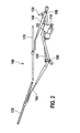
- FIG. 2 shows another exemplary view of the windshield wiper device 100.
- the transmission 120 comprises a gear rod 125.
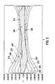
- FIG. 3 shows a schematic representation of a relationship between a rotation angle a of the drive means 110 and the drive shaft 115 and a force exerted by the link rod 125 of the transmission 120 force F. Because of the angular dependence of the gear ratio of the transmission 120 is the force exerted by the link rod 125 of the transmission 120 force F depending on the angle a of the drive means 110 and the drive shaft 115. In FIG. 3 is on the horizontal axis of the angle a of the drive shaft 115, plotted on the vertical axis, the rod force F of the link rod 125 of the transmission 120.
- a first rod force profile 210 shows the force F exerted by the link rod 125 of the transmission 120 in the event that the drive means 110 outputs a constant first torque, for example 40 Nm.
- a second bar force profile 220, a third bar force curve 230, a fourth bar force curve 240, a fifth bar force curve 250, a sixth bar force curve 260, a seventh bar force curve 270 and an eighth bar force curve 280 show the course of the bar force F for other constant dependent on the angle a of the drive shaft 115 Values of the torque output by the drive means 110.
- the second bar force profile 220 may correspond to a torque of 30 Nm
- the third bar force profile 230 to a torque of 20 Nm
- the fourth bar force curve to a torque of 10 Nm. In all cases, the course of the rod force F due to the angular dependence of the transmission ratio of the transmission 120 from the angle a of the drive shaft 115 is dependent.
- the desired operating cases on the window 190 of the motor vehicle are defined in a first step. These include, for example, the operating moments on wiper bearings of the windshield wiper device 100, which are required to wind the wiper arm 160 and the wiper blade 170 at the wind speeds occurring at maximum vehicle speed at each location or angle of the wiper arm 160 with the desired speeds and accelerations operate.
- the desired forces or force changes to be applied if the wiper blade 170 encounters an obstacle such as a snow wedge or the wiper blade 170 is frozen to the disc 190.
- the operating map thus obtained on the disk 190 can be translated in a second step by suitable calculation methods in an operating map 300 of the transmission 120, which indicates the maximum desired bar force F of the link rod 125 of the transmission 120 for each angle a of the drive shaft 115.
- the mechanical relationships between the gear 120 and the wiper blade 170 are taken into account.
- the resulting operating map 300 of the transmission 120 is in FIG. 3 shown.
- the hatched area of the operating map 300 indicates permissible values of the rod force F of the linkage 125 of the gearbox 120 for each angle a of the drive shaft 115.
- the permissible value ranges of the operating map 300 are limited by a first limit curve 310 and by a second limit curve 320.
- the positive values of the allowable rod force F limited by the first limit curve 310 may occur when the wiper blade 170 moves in a first direction, the negative values of the allowable rod force F limited by the second limit curve 320 when moving the wiper blade 170 in a second direction.
- each Torque of the drive means 110 can be determined for each angle a of the drive shaft 115 from the intersection of the first limit curve 310 with one of the bar force profiles 210, 220, 230, 240, 250, 260, 270, 280. This applies correspondingly to the second limit curve 220.
- a permissible maximum positive and negative torque of the drive means 110 can thus be determined for each angle ⁇ of the drive means 115 in a third step the operating map 140 of the drive means 110 is available.
- the thus obtained operating map 140 of the drive means 110 indicates for each angle a of the drive shaft 115 a maximum allowable positive and negative output from the drive means 110 torque.
- the control unit 130 uses the operation map 140 for controlling the drive means 110. This will be explained below.
- FIG. 4 shows a schematic representation of a graph in which a relationship between the applied on the horizontal axis, output by the drive means 110 torque M and the plotted on the vertical axis speed n of the drive means 110 is shown.
- an indirectly proportional linear relationship which is determined by the structure of the drive means 110 and represented by a characteristic curve 400.
- the drive means 110 runs at a maximum speed n, which corresponds to the intersection of the characteristic curve 400 with the vertical axis of the graph of FIG. 4 equivalent.
- Blockadefall the drive means gives no more rotational movement, but exerts a maximum torque M, which corresponds to the intersection of the characteristic curve 400 with the horizontal axis.
- the position of the characteristic 400 in the diagram of FIG. 4 is determined by the duty cycle of the pulse width modulated voltage signal with which the control unit 130 controls the drive means 110.
- a variation of the duty cycle leads to a parallel shift of the characteristic curve 400, in which the slope of the characteristic curve 400 remains unchanged.
- the controller 130 attempts to adjust the duty cycle of the pulse width modulated voltage signal so that the determined by means of the tachometer 150 actual speed of the drive means 110 of a predetermined desired Speed corresponds.
- the predetermined desired speed may be constant or dependent on the angle a of the drive shaft 115. In the latter case, the control unit 130 can take the desired speed from the operating map 140.
- the control unit 130 can determine the torque actually output by the drive means 110.
- the controller 130 compares this actual torque with the allowable torque range defined by the operating map 140 for the current angle a of the drive shaft 115. If the controller 130 determines that the allowable range has been exceeded, it takes appropriate action.
- the torque M output by the drive means 110 is initially limited by reducing the speed n.
- the torque associated with the first point 430 can likewise be stored in the operating map 140 or can be calculated from the maximum torque stored in the operating map 140, which corresponds to the second point 440.
- the permissible torque M output by the drive means 110 corresponds to the value at the fourth point 460, then correspondingly all the operating points in a second operating range 420 are permissible.
- the characteristic curve is bent when reaching a third point 450 and limited with a straight line to the torque of the fourth point 460.
- the torque M output by the drive means 110 is the values stored in the operating map 140 for no angle a of the drive shaft 115 permanently exceeds.
- an excessive load of the transmission 120, the wiper arm 160, the wiper blade 170, and other components of the windshield wiper device 100 can be prevented.
- the components of the windshield wiper device 100 can be formed with less mechanical reserves, resulting in a lower weight, a smaller footprint and lower manufacturing costs.
- the control unit 130 may respond in a predetermined manner. For example, the controller 130 may disable the drive means 110. Alternatively, the controller 130 may reverse the direction of rotation of the drive means 110. The controller 130 may also make another attempt to move the wiper blade 170 over the critical area by means of the drive means 110.
- the angle-dependent elasticity of the transmission 120 can be used to determine which of the wiper arms is blocked.
- the control unit determines a torque gradient from the current and previous torques output by the drive means 110 and monitors that it does not exceed the value stored in the operating map 140.
Landscapes
- Engineering & Computer Science (AREA)
- Mechanical Engineering (AREA)
- Control Of Direct Current Motors (AREA)
- Electric Propulsion And Braking For Vehicles (AREA)
Description
- Die Erfindung betrifft eine Scheibenwischvorrichtung gemäß dem Oberbegriff des Patentanspruchs 1.
- Zur Steuerung von Scheibenwischvorrichtungen sind zahlreiche Verfahren bekannt. Die
DE 101 44 985 A1 beschreibt ein Verfahren zur Steuerung einer Scheibenwischvörrichtung mittels einer Antriebseinrichtung und eines Getriebes mit einem von der Stellung des Getriebes abhängigen Übersetzungsverhältnis, bei dem das von der Antriebseinrichtung über eine Antriebswelle abgegebene Drehmoment zu jedem Zeitpunkt unter Berücksichtigung des Übersetzungsverhältnisses bestimmt wird. Dabei folgt das maximal abgegebene Drehmoment grob einem maximal benötigten Drehmoment. Die Reduktion des abgegebenen Drehmoments erfolgt durch eine Begrenzung eines elektrischen Stroms. Es ist auch bekannt, das von der Antriebseinrichtung abgegebene Drehmoment für bestimmte Stellungen der Scheibenwischvorrichtung durch eine Reduzierung der Versorgungsspannung zu begrenzen. Die Anwendbarkeit dieses Verfahrens ist dadurch beschränkt, dass die Versorgungsspannung lediglich auf rund 50 % ihres Maximalwerts abgesenkt werden kann und eine Reduzierung der Versorgungsspannung eine reduzierte Drehgeschwindigkeit und damit eine reduzierte Dynamik der Antriebseinrichtung mit sich bringt. Es existieren auch einfachere Verfahren, bei denen die Geschwindigkeit der Antriebseinrichtung im Bereich der Umkehrlagen reduziert wird. - Die
DE 10 2006 061 679 A1 beschreibt ein Verfahren zum Ansteuern einer Wischanlage bei dem eine Wischhäufigkeit eines Wischerarms reduziert wird, falls ein am Wischarm wirkendes Lastmoment eine vorgegebene Lastschwelle überschreitet. DieDE 10 2007 022 213 A1 beschreibt ein Verfahren zum Betreiben eines Elektromotors, bei dem der Elektromotor in Abhängigkeit einer Temperatur des Motors so angesteuert wird, dass der Motor ein konstantes Drehmoment abgibt und ein maximaler Motorstrom nicht überschritten wird. - Aufgabe der vorliegenden Erfindung ist es, eine verbesserte Scheibenwischvorrichtung bereitzustellen. Diese Aufgabe wird durch eine Scheibenwischvorrichtung mit den Merkmalen des Anspruchs 1 gelöst.
- Eine erfindungsgemäße Scheibenwischvorrichtung weist ein Antriebsmittel und ein Steuergerät für das Antriebsmittel auf. Dabei ist ein Betriebskennfeld vorgesehen, in dem ein von dem Antriebsmittel abzugebendes maximales Drehmoment und eine minimale Drehzahl des Antriebsmittels hinterlegt sind. Vorteilhafterweise kann das Steuergerät dann eine Einhaltung des maximal abzugebenden Drehmoments und der minimalen Drehzahl des Antriebsmittels überwachen und im Fall einer Überschreitung des maximal abzugebenden Drehmoments geeignet reagieren, beispielsweise durch sofortiges Abschalten der Scheibenwischvorrichtung oder durch einen Wechsel der Drehrichtung des Antriebsmittels. Vorteilhafterweise werden dadurch ungewollte Betriebs- und Belastungszustände vermieden. Beim Einsatz von Kurbelgetrieben durch den Kniehebeleffekt theoretisch mögliche unendlich hohe Kräfte können nicht mehr auftreten. Dadurch sinkt die mechanische Belastung von Stangen, Lagern, Kurbelplatten, Befestigungspunkten und anderen mechanischen Bauteilen der Scheibenwischvorrichtung. In der Folge wird die Verwendung dünnerer Wandstärken, kürzerer Lagerstellen, verkleinerter Drehgelenke und alternativer Wertstoffe mit geringerer Festigkeit ermöglicht. Dadurch lassen sich Gewicht, Bauraum und Kosten in hohem Umfang einsparen. Dies erlaubt den Einsatz der erfindungsgemäßen Scheibenwischvorrichtung auch in engen und zerklüfteten Kraftfahrzeugumgebungen. Durch das reduzierte Gewicht sinkt außerdem die mittlere Stromaufnahme der Scheibenwischvorrichtung, was einen direkten Beitrag zur Reduzierung des Schadstoffausstoßes des Kraftfahrzeugs liefert.
- Erfindungsgemäß sind im Betriebskennfeld für unterschiedliche Winkelstellungen einer Welle des Antriebsmittels jeweils ein von dem Antriebsmittel abzugebendes maximales Drehmoment und eine minimale Drehzahl des Antriebsmittels hinterlegt. Vorteilhafterweise können dadurch in unterschiedlichen Stellungen der Scheibenwischvorrichtung benötigte unterschiedliche Drehmomente und Drehzahlenberücksichtigt werden.
- In einer Weiterbildung ist im Betriebskennfeld für unterschiedliche Winkelstellungen einer Welle des Antriebsmittels zusätzlich jeweils ein weiterer Drehmoment-Grenzwert hinterlegt. Vorteilhafterweise kann das Steuergerät dann bei einer Überschreitung des maximalen Drehmoments versuchen, das Drehmoment durch eine Reduzierung der Drehzahl zu reduzieren, und erst, wenn auch der zweite Drehmoment-Grenzwert überschritten wird, das Antriebsmittel komplett abschalten.
- In einer Weiterbildung der Scheibenwischvorrichtung ist dem Antriebsmittel ein Getriebe nachgeordnet, das eine Bewegung des Antriebsmittels auf eine Wischerwelle vermittelt, wobei das Getriebe ein Übersetzungsverhältnis aufweist, das von der Winkelstellung der Welle des Antriebsmittels abhängt. Vorteilhafterweise kann das Betriebskennfeld die Winkelabhängigkeit des Übersetzungsverhältnisses berücksichtigen.
- Zweckmäßigerweise ist das Antriebsmittel durch ein pulsweitenmoduliertes Spannungssignal ansteuerbar und das Steuergerät dazu ausgebildet, ein Tastverhältnis des pulsweitenmodulierten Spannungssignals derart zu regeln, dass sich eine im Betriebskennfeld hinterlegte minimale Drehzahl des Antriebsmittels einstellt und ein von dem Antriebsmittel abgegebenes Drehmoment ein im Betriebskennfeld hinterlegtes maximales Drehmoment nicht übersteigt. Vorteilhafterweise kann dadurch sichergestellt werden, dass die Scheibenwischvorrichtung nur innerhalb eines erlaubten Parameterbereichs betrieben wird.
- Bevorzugt ist eine Vorrichtung zum Bestimmen einer Drehzahl des Antriebsmittels vorgesehen. Dabei ist das Steuergerät ausgebildet, anhand der Drehzahl des Antriebsmittels und des Tastverhältnisses des pulsweitenmodulierten Spannungssignals das von dem Antriebsmittel abgegebene Drehmoment zu ermitteln. Vorteilhafterweise können dadurch Störungen der Scheibenwischvorrichtung erkannt werden.
- Besonders bevorzugt ist das Steuergerät ausgebildet, das Antriebsmittel abzuschalten oder eine Antriebsrichtung des Antriebsmittels umzukehren, falls das von dem Antriebsmittel abgegebene Drehmoment das im Betriebskennfeld vorgesehene maximale Drehmoment übersteigt. Vorteilhafterweise kann dadurch eine Beschädigung der Scheibenwischvorrichtung verhindert werden.
- Die Erfindung wird nun anhand der beigefügten Figuren näher erläutert. Dabei werden für gleiche oder gleich wirkende Elemente einheitliche Bezugszeichen verwendet. Es zeigen:
-
Figur 1 ein schematisches Blockschaltbild einer Scheibenwischvorrichtung; -
Figur 2 eine weitere Ansicht der Scheibenwischvorrichtung; -
Figur 3 ein Betriebskennfeld einer Scheibenwischvorrichtung; und -
Figur 4 eine Regelcharakteristik eines Antriebsmittels der Scheibenwischvorrichtung. -
Figur 1 zeigt eine Scheibenwischvorrichtung 100 in schematisierter Darstellung. Die Scheibenwischvorrichtung 100 weist einen Wischerarm 160 auf, an dem ein Wischblatt 170 befestigt ist, das zum Wischen einer Scheibe 190 dient. Die Scheibe 190 kann beispielsweise eine Scheibe eines Kraftfahrzeugs sein. Der Wischerarm 160 kann über eine Wischerwelle 180 in eine schwenkende Bewegung versetzt werden. Ein Antriebsmittel 110 bringt hierzu eine Antriebswelle 115 in eine Drehbewegung, die über ein Getriebe 120 auf die Wischerwelle 180 übertragen wird. Das Antriebsmittel 110 kann ein Elektromotor, beispielsweise ein reversierender Elektromotor, sein. Das Getriebe 120 kann beispielsweise ein Kurbelgetriebe sein. In diesem Fall weist das Getriebe 120 ein Übersetzungsverhältnis auf, das von einer Winkelstellung der Antriebswelle 115 abhängt. Das Getriebe 120 und der Wischerarm 160 weisen außerdem eine Elastizität auf, die ebenfalls von der Winkelstellung der Antriebswelle 115 abhängen kann. - Das Antriebsmittel 110 wird mit einem pulsweitenmodulierten Spannungssignal angesteuert. Das Tastverhältnis des pulsweitenmodulierten Spannungssignals legt dabei einen effektiven Spannungswert fest und bestimmt dadurch die Winkelgeschwindigkeit, mit der das Antriebsmittel 110 die Antriebswelle 115 antreibt. Die Ansteuerung des Antriebsmittels 110 erfolgt durch ein Steuergerät 130. Das Steuergerät 130 kann beispielsweise als Mikrocontroller oder Mikrocomputer ausgebildet sein. Das Steuergerät 130 kann auch mit einem anderen Steuergerät eines Kraftfahrzeugs integriert sein. Das Steuergerät 130 hat Zugriff auf ein Betriebskennfeld 140. Das Betriebskennfeld 140 kann beispielsweise als Wertetabelle in einem nichtflüchtigen Datenspeicher ausgebildet sein. Das Betriebskennfeld 140 kann auch im Steuergerät 130 integriert sein. Außerdem ist das Steuergerät 130 mit einem Drehzahlmesser 150 verbunden, der dazu ausgebildet ist, eine Anzahl von Umdrehungen oder eine Drehzahl des Antriebsmittels 110 bzw. der Antriebswelle 115 zu ermitteln. Der Drehzahlmesser 150 kann auch als Ortssensor ausgebildet sein, der eine Ortsänderung der Antriebswelle 115 ermittelt.
- Im Betriebskennfeld 140 ist ein maximales vom Antriebsmittel 110 abzugebendes Drehmoment hinterlegt. Bevorzugt ist das vom Antriebsmittel 110 abzugebende maximale Drehmoment im Betriebskennfeld 140 abhängig von einer Winkelstellung des Antriebsmittels 110 bzw. der Antriebswelle 115 hinterlegt. Das Steuergerät 130 steuert das Antriebsmittel 110 derart an, dass das im Betriebskennfeld 140 hinterlegte maximale Drehmoment nicht überschritten wird. Kommt es zu einem Betriebsfall, bei dem das vom Antriebsmittel 110 abgegebene Drehmoment das im Betriebskennfeld 140 vorgesehene maximale Drehmoment überschreiten würde, so kann das Steuergerät 130 in festgelegter Form darauf reagieren. Beispielsweise kann das Steuergerät 130 das Antriebsmittel 110 abschalten oder eine Drehrichtung des Antriebsmittels 110 umkehren.
- Das Betriebskennfeld 140 kann auch für jede Winkelstellung des Antriebsmittels 110 bzw. der Antriebswelle 115 zwei Drehmomentgrenzwerte vorhalten. Kommt es zu einer Überschreitung des ersten Drehmomentgrenzwerts, so versucht das Steuergerät 130, das abgegebene Drehmoment zu reduzieren. Wird dennoch auch der zweite Grenzwert überschritten, so schaltet das Steuergerät 130 das Antriebsmittel 110 ab. Nachfolgend wird erläutert, wie die im Betriebskennfeld 140 hinterlegten Drehmomentgrenzwerte festgelegt werden können.
- Das Betriebskennfeld 140 kann auch für jede Winkelstellung des Antriebsmittels 110 bzw. der Antriebswelle 115 eine gewünschte Drehzahl des Antriebsmittels 110 vorhalten. Die gewünschte Drehzahl kann für alle Winkelstellungen des Antriebsmittels 110 bzw. der Antriebswelle 115 gleich sein oder von der Winkelstellungen des Antriebsmittels 110 bzw. der Antriebswelle 115 abhängen. Das Steuergerät 130 steuert das Antriebsmittel 110 dann derart an, dass sich die jeweilige gewünschte Drehzahl einstellt.
-
Figur 2 zeigt eine weitere exemplarische Ansicht der Scheibenwischvorrichtung 100. Insbesondere zeigtFigur 2 , dass das Getriebe 120 eine Getriebestange 125 aufweist. -
Figur 3 zeigt in schematischer Darstellung einen Zusammenhang zwischen einem Drehwinkel a des Antriebsmittels 110 bzw. der Antriebswelle 115 und einer von der Gelenkstange 125 des Getriebes 120 ausgeübten Kraft F. Wegen der Winkelabhängigkeit des Übersetzungsverhältnisses des Getriebes 120 ist die von der Gelenkstange 125 des Getriebes 120 ausgeübte Kraft F abhängig vom Winkel a des Antriebsmittels 110 bzw. der Antriebswelle 115. InFigur 3 ist auf der horizontalen Achse der Winkel a der Antriebswelle 115, auf der vertikalen Achse die Stangenkraft F der Gelenkstange 125 des Getriebes 120 aufgetragen. Ein erster Stangenkraftverlauf 210 zeigt die von der Gelenkstange 125 des Getriebes 120 ausgeübte Kraft F für den Fall, dass das Antriebsmittel 110 ein konstantes erstes Drehmoment, beispielsweise 40 Nm, abgibt. Ein zweiter Stangenkraftverlauf 220, ein dritter Stangenkraftverlauf 230, ein vierter Stangenkraftverlauf 240, ein fünfter Stangenkraftverlauf 250, ein sechster Stangenkraftverlauf 260, ein siebter Stangenkraftverlauf 270 und ein achter Stangenkraftverlauf 280 zeigen den vom Winkel a der Antriebswelle 115 abhängigen Verlauf der Stangenkraft F für andere konstante Werte des vom Antriebsmittel 110 abgegebenen Drehmoments. Beispielsweise können der zweite Stangenkraftverlauf 220 einem Drehmoment von 30 Nm, der dritte Stangenkraftverlauf 230 einem Drehmoment von 20 Nm und der vierte Stangenkraftverlauf einem Drehmoment von 10 Nm entsprechen. In allen Fällen ist der Verlauf der Stangenkraft F wegen der Winkelabhängigkeit des Übersetzungsverhältnisses des Getriebes 120 vom Winkel a der Antriebswelle 115 abhängig. - Zum Erzeugen der im Betriebskennfeld 140 hinterlegten Wertetabelle werden in einem ersten Schritt die gewollten Betriebsfälle an der Scheibe 190 des Kraftfahrzeugs definiert. Hierzu gehören beispielsweise die Betriebsmomente an Wischerlagern der Scheibenwischvorrichtung 100, die erforderlich sind, um den Wischerarm 160 und das Wischblatt 170 bei den bei maximaler Fahrgeschwindigkeit des Kraftfahrzeugs auftretenden Windlasten an jedem Ort beziehungsweise jedem Winkel der Wischbewegung des Wischerarms 160 mit den gewünschten Geschwindigkeiten und Beschleunigungen zu betreiben. Außerdem können die gewollten Kräfte oder Kraftänderungen festgelegt werden, die ausgeübt werden sollen, falls das Wischblatt 170 auf ein Hindernis wie beispielsweise einen Schneekeil trifft oder das Wischblatt 170 an der Scheibe 190 festgefroren ist.
- Das so gewonnene Betriebskennfeld an der Scheibe 190 kann in einem zweiten Schritt durch geeignete Berechnungsverfahren in ein Betriebskennfeld 300 des Getriebes 120 übersetzt werden, das für jeden Winkel a der Antriebswelle 115 die maximale gewollte Stangenkraft F der Gelenkstange 125 des Getriebes 120 angibt. Bei der Übersetzung des Betriebskennfelds an der Scheibe 190 in das Betriebskennfeld des Getriebes 120 werden die mechanischen Zusammenhänge zwischen dem Getriebe 120 und dem Wischblatt 170 berücksichtigt.
- Das entstehende Betriebskennfeld 300 des Getriebes 120 ist in
Figur 3 dargestellt. Der schraffierte Bereich des Betriebskennfelds 300 gibt für jeden Winkel a der Antriebswelle 115 zulässige Werte der Stangenkraft F der Gelenkstange 125 des Getriebes 120 an. Die zulässigen Wertebereiche des Betriebskennfelds 300 werden durch eine erste Grenzkurve 310 und durch eine zweite Grenzkurve 320 begrenzt. Die durch die erste Grenzkurve 310 begrenzten positiven Werte der zulässigen Stangenkraft F können bei einer Bewegung des Wischblatts 170 in eine erste Richtung, die durch die zweite Grenzkurve 320 begrenzten negativen Werte der zulässigen Stangenkraft F beim Bewegen des Wischblatts 170 in eine zweite Richtung auftreten. - Wegen der Winkelabhängigkeit des Übersetzungsverhältnisses des Getriebes 120 und der winkelabhängigen Elastizität des Getriebes 120 sind zum Erzeugen der zulässigen Werte der Stangenkraft F auf der ersten Grenzkurve 310 bei unterschiedlichen Winkeln a der Antriebswelle 115 unterschiedlichen vom Antriebsmittel 110 abgegebene Drehmomente notwendig. Das jeweils benötigte Drehmoment des Antriebsmittel 110 kann für jeden Winkel a der Antriebswelle 115 aus dem Schnittpunkt der ersten Grenzkurve 310 mit einem der Stangenkraftverläufe 210, 220, 230, 240, 250, 260, 270, 280 ermittelt werden. Dies gilt entsprechend für die zweite Grenzkurve 220. Aus den Schnittpunkten der Grenzkurven 310, 320 mit den Stangenkraftverläufen 210 bis 280 kann also in einem dritten Schritt für jeden Winkel a der Antriebswelle 115 ein zulässiges maximales positives und negatives Drehmoment des Antriebsmittels 110 ermittelt werden, wodurch das Betriebskennfeld 140 des Antriebsmittels 110 erhältlich ist. Das so erhaltene Betriebskennfeld 140 des Antriebsmittels 110 gibt für jeden Winkel a der Antriebswelle 115 ein maximal zulässiges positives und negatives vom Antriebsmittel 110 abgegebenes Drehmoment an. Das Steuergerät 130 nutzt das Betriebskennfeld 140 zur Steuerung des Antriebsmittels 110. Dies wird nachfolgend erläutert.
-
Figur 4 zeigt in schematischer Darstellung einen Graphen, in dem ein Zusammenhang zwischen dem auf der horizontalen Achse aufgetragenen, vom Antriebsmittel 110 abgegebenen Drehmoment M und der auf der vertikalen Achse aufgetragenen Drehzahl n des Antriebsmittels 110 gezeigt ist. Zwischen beiden Größen besteht ein indirekt proportionaler linearer Zusammenhang, der durch den Aufbau des Antriebsmittels 110 festgelegt und durch eine Kennlinie 400 dargestellt ist. In unbelastetem Zustand läuft das Antriebsmittel 110 mit einer maximalen Drehzahl n, die dem Schnittpunkt der Kennlinie 400 mit der vertikalen Achse des Graphen derFigur 4 entspricht. Im Blockadefall gibt das Antriebsmittel überhaupt keine Drehbewegung mehr ab, übt jedoch ein maximales Drehmoment M aus, das dem Schnittpunkt der Kennlinie 400 mit der horizontalen Achse entspricht. - Die Lage der Kennlinie 400 im Diagramm der
Figur 4 wird durch das Tastverhältnis des pulsweitenmodulierten Spannungssignals bestimmt, mit dem das Steuergerät 130 das Antriebsmittel 110 ansteuert. Eine Variation des Tastverhältnisses führt zu einer parallelen Verschiebung der Kennlinie 400, bei der die Steigung der Kennlinie 400 unverändert bleibt. - Das Steuergerät 130 versucht, das Tastverhältnis des pulsweitenmodulierten Spannungssignals so einzuregeln, dass die mit Hilfe des Drehzahlmessers 150 ermittelte tatsächliche Drehzahl des Antriebsmittels 110 einer vorgegebenen gewünschten Drehzahl entspricht. Die vorgegebene gewünschte Drehzahl kann dabei konstant oder vom Winkel a der Antriebswelle 115 abhängig sein. In letzterem Fall kann das Steuergerät 130 die gewünschte Drehzahl dem Betriebskennfeld 140 entnehmen.
- Aus dem durch den Regelkreis aufgefundenen Tastverhältnis, der ermittelten Drehzahl des Antriebsmittels 110 und einer Kenntnis der Kennlinie 400 des Antriebsmittels 110 kann das Steuergerät 130 das vom Antriebsmittel 110 tatsächlich abgegebene Drehmoment bestimmen. Das Steuergerät 130 vergleicht dieses tatsächliche Drehmoment mit dem durch das Betriebskennfeld 140 festgelegten zulässigen Bereich des Drehmoments für den aktuellen Winkel a der Antriebswelle 115. Stellt das Steuergerät 130 fest, dass der zulässige Bereich überschritten wurde, so ergreift es geeignete Massnahmen.
- Entspricht das im Betriebskennfeld 140 festgelegte maximale vom Antriebsmittel 110 abgegebene Drehmoment beispielsweise dem zweiten Punkt 440 im Diagramm der
Figur 4 , so sind alle Betriebspunkte innerhalb des ersten Betriebsbereichs 410 zulässig. Erreicht der Betriebspunkt des Antriebsmittels 110 die Drehzahl n und das Drehmoment M, die dem ersten Punkt 430 inFigur 4 entsprechen, so wird das vom Antriebsmittel 110 abgegebene Drehmoment M zunächst durch Reduktion der Drehzahl n begrenzt. Anschaulich kann dies so verstanden werden, dass die Kennlinie des Antriebsmittels 110 im ersten Punkt 430 abgeknickt und mit einer Geraden auf das zulässige Drehmoment M im zweiten Punkt 440 begrenzt wird. Das dem ersten Punkt 430 zugehörige Drehmoment kann dabei ebenfalls im Betriebskennfeld 140 hinterlegt sein oder aus dem im Betriebskennfeld 140 hinterlegten maximalen Drehmoment, das dem zweiten Punkt 440 entspricht, errechnet werden. - Entspricht das zulässige vom Antriebsmittel 110 abgegebene Drehmoment M dem Wert am vierten Punkt 460, so sind entsprechend alle Betriebspunkte in einem zweiten Betriebsbereich 420 zulässig. Dabei wird die Kennlinie bei Erreichen eines dritten Punkts 450 abgeknickt und mit einer Geraden auf das Drehmoment des vierten Punkts 460 begrenzt.
- Durch dieses Verfahren wird sichergestellt, dass das vom Antriebsmittel 110 abgegebene Drehmoment M die im Betriebskennfeld 140 hinterlegten Werte für keinen Winkel a der Antriebswelle 115 dauerhaft überschreitet. Dadurch kann eine übermäßige Belastung des Getriebes 120, des Wischerarms 160, des Wischblatts 170 und anderer Bauteile der Scheibenwischvorrichtung 100 verhindert werden. In der Folge können die Komponenten der Scheibenwischvorrichtung 100 mit weniger mechanischen Reserven ausgebildet werden, wodurch sich ein geringeres Gewicht, ein geringerer Platzbedarf und geringere Herstellungskosten ergeben.
- Im Fall einer Blockade des Wischblatts 170, beispielsweise durch einen Schneekeil auf der Scheibe 190 oder durch ein Festfrieren des Wischblatts 170 auf der Scheibe 190, gelingt es dem Steuergerät 130 nicht, das Tastverhältnis des pulsweitenmodulierten Spannungssignal derart einzuregeln, dass sich die gewünschte Drehzahl n des Antriebsmittels 110 einstellt und das vom Antriebsmittel 110 abgegebene Drehmoment M den im Betriebskennfeld 140 hinterlegten Wert nicht überschreitet. In diesem Fall kann das Steuergerät 130 auf vorherbestimmte Weise reagieren. Beispielsweise kann das Steuergerät 130 das Antriebsmittel 110 abschalten. Alternativ kann das Steuergerät 130 die Drehrichtung des Antriebsmittels 110 umkehren. Das Steuergerät 130 kann auch einen weiteren Versuch durchführen, das Wischblatt 170 mittels des Antriebsmittels 110 über den kritischen Bereich hinweg zu bewegen.
- Falls die Scheibenwischvorrichtung 100 mit zwei Wischarmen aufweist, kann, wenn der zulässige Betriebsbereich 410, 420 verlassen wird, aufgrund der winkelabhängigen Elastizität des Getriebes 120 ermittelt werden, welcher der Wischarme blockiert ist.
- Zusätzlich zu den im Betriebskennfeld 140 hinterlegten maximal zulässigen Drehmomenten des Antriebsmittels 110 können auch maximal zulässige zeitliche Drehmomentgradienten vorgesehen sein. Die maximal zulässigen Drehmomentgradienten können ebenfalls von der Winkelstellung des Antriebsmittels 110 bzw. der Antriebswelle 115 abhängen. In diesem Fall ermittelt das Steuergerät aus den jeweils gegenwärtigen und vorhergegangenen vom Antriebsmittel 110 abgegebenen Drehmomenten einen Drehmomentgradient und überwacht, dass dieser den im Betriebskennfeld 140 hinterlegten Wert nicht überschreitet.
Claims (6)
- Scheibenwischvorrichtung (100)
mit einem Antriebsmittel (110) und einem Steuergerät (130) für das Antriebsmittel (110),
dadurch gekennzeichnet, dass
ein Betriebskennfeld (140) vorgesehen ist, in dem für unterschiedliche Winkelstellungen einer Welle (115) des Antriebsmittels (110) jeweils ein von dem Antriebsmittel (110) abzugebendes maximales Drehmoment und eine minimale Drehzahl des Antriebsmittels (110) hinterlegt sind. - Scheibenwischvorrichtung (100) nach Anspruch 1,
dadurch gekennzeichnet, dass
im Betriebskennfeld (140) für unterschiedliche Winkelstellungen einer Welle (115) des Antriebsmittels (110) zusätzlich jeweils ein weiterer Drehmoment-Grenzwert hinterlegt ist. - Scheibenwischvorrichtung (100) nach einem der Ansprüche 1 oder 2,
dadurch gekennzeichnet, dass
dem Antriebsmittel (110) ein Getriebe (120) nachgeordnet ist, das eine Bewegung des Antriebsmittels (110) auf eine Wischerwelle (180) vermittelt, wobei das Getriebe (120) ein Übersetzungsverhältnis aufweist, das von der Winkelstellung der Welle (115) des Antriebsmittels (110) abhängt. - Scheibenwischvorrichtung (100) nach einem der vorhergehenden Ansprüche,
dadurch gekennzeichnet, dass
das Antriebsmittel (110) durch ein pulsweitenmoduliertes Spannungssignal ansteuerbar ist,
und das Steuergerät (130) dazu ausgebildet ist, ein Tastverhältnis des pulsweitenmodulierten Spannungssignals derart zu regeln, dass sich eine im Betriebskennfeld (140) hinterlegte minimale Drehzahl des Antriebsmittels (110) einstellt und ein von dem Antriebsmittel (110) abgegebenes Drehmoment ein im Betriebskennfeld (140) hinterlegtes maximales Drehmoment nicht übersteigt. - Scheibenwischvorrichtung (100) nach einem der vorhergehenden Ansprüche,
dadurch gekennzeichnet, dass
eine Vorrichtung (150) zum Bestimmen einer Drehzahl des Antriebsmittels (110) vorgesehen ist,
und das Steuergerät (130) ausgebildet ist, anhand der Drehzahl des Antriebsmittels (110) und des Tastverhältnisses des pulsweitenmodulierten Spannungssignals das von dem Antriebsmittel (110) abgegebene Drehmoment zu ermitteln. - Scheibenwischvorrichtung (100) nach Anspruch 5,
dadurch gekennzeichnet, dass
das Steuergerät (130) ausgebildet ist, das Antriebsmittel (110) abzuschalten oder eine Antriebsrichtung des Antriebsmittels (110) umzukehren, falls das von dem Antriebsmittel (110) abgegebene Drehmoment das im Betriebskennfeld (140) vorgesehene maximale Drehmoment übersteigt.
Applications Claiming Priority (3)
| Application Number | Priority Date | Filing Date | Title |
|---|---|---|---|
| DE102009037922 | 2009-08-19 | ||
| DE102009045183A DE102009045183A1 (de) | 2009-08-19 | 2009-11-25 | Scheibenwischvorrichtung |
| PCT/EP2010/059777 WO2011020649A1 (de) | 2009-08-19 | 2010-07-08 | Scheibenwischvorrichtung |
Publications (2)
| Publication Number | Publication Date |
|---|---|
| EP2467283A1 EP2467283A1 (de) | 2012-06-27 |
| EP2467283B1 true EP2467283B1 (de) | 2014-09-10 |
Family
ID=43495534
Family Applications (1)
| Application Number | Title | Priority Date | Filing Date |
|---|---|---|---|
| EP10728716.1A Active EP2467283B1 (de) | 2009-08-19 | 2010-07-08 | Scheibenwischvorrichtung |
Country Status (6)
| Country | Link |
|---|---|
| US (1) | US9707931B2 (de) |
| EP (1) | EP2467283B1 (de) |
| CN (1) | CN102470824B (de) |
| BR (1) | BR112012003610A2 (de) |
| DE (1) | DE102009045183A1 (de) |
| WO (1) | WO2011020649A1 (de) |
Families Citing this family (6)
| Publication number | Priority date | Publication date | Assignee | Title |
|---|---|---|---|---|
| DE102010040138A1 (de) * | 2010-09-02 | 2012-03-08 | Robert Bosch Gmbh | Verfahren zum Reduzieren des Motor-Drehmoments für Wischantriebe |
| US9031390B2 (en) * | 2012-03-26 | 2015-05-12 | Asmo Co., Ltd. | Wiper device |
| US10023152B2 (en) | 2016-06-29 | 2018-07-17 | Ford Global Technologies, Llc | Method of preventing a windshield wiper from freezing to a windshield and related circuit |
| JP6816576B2 (ja) * | 2017-03-13 | 2021-01-20 | 株式会社デンソー | ワイパ装置 |
| US11420594B2 (en) | 2017-08-28 | 2022-08-23 | Rosemount Aerospace Inc. | Configurable variable sweep variable speed wiper system |
| DE102018204454A1 (de) * | 2018-03-22 | 2019-09-26 | Volkswagen Aktiengesellschaft | Antriebseinheit für ein Scheibenwischersystem |
Family Cites Families (11)
| Publication number | Priority date | Publication date | Assignee | Title |
|---|---|---|---|---|
| US4663575A (en) * | 1986-02-21 | 1987-05-05 | United Technologies Automotive, Inc. | Speed control for a window wiper system |
| DE4330112C2 (de) * | 1993-09-06 | 1998-01-29 | Bayerische Motoren Werke Ag | Schaltanordnung zur Steuerung der Geschwindigkeit eines Scheibenwischers in Kraftfahrzeugen |
| US5526460A (en) * | 1994-04-25 | 1996-06-11 | Black & Decker Inc. | Impact wrench having speed control circuit |
| BE1011560A3 (nl) * | 1997-11-21 | 1999-10-05 | Picanol Nv | Weefmachine en werkwijze voor het sturen en/of het starten en/of het stoppen van een aandrijfmotor. |
| FR2824204B1 (fr) * | 2001-04-30 | 2003-06-13 | Valeo Systemes Dessuyage | Procede de regulation electronique d'un moteur electrique |
| DE10144985B4 (de) * | 2001-09-12 | 2012-10-31 | Robert Bosch Gmbh | Verfahren zur Steuerung einer Scheibenwischvorrichtung sowie eine Scheibenwischvorrichtung für ein Kraftfahrzeug |
| CN2774001Y (zh) | 2005-01-25 | 2006-04-19 | 武汉大学 | 一种雨刮电机自动无级调速控制器 |
| DE602005013089D1 (de) * | 2005-10-07 | 2009-04-16 | Emotron Ab | Lastüberwachung |
| DE102006061679B4 (de) * | 2006-12-28 | 2019-06-19 | Robert Bosch Gmbh | Vorrichtung und Verfahren zur Ansteuerung einer Antriebseinheit einer Wischanlage |
| DE102007022213A1 (de) | 2007-05-11 | 2008-11-13 | Robert Bosch Gmbh | Verfahren und Vorrichtung zur Begrenzung des Motorstroms |
| US8175790B2 (en) * | 2009-02-05 | 2012-05-08 | Caterpillar Inc. | Engine droop governor and method |
-
2009
- 2009-11-25 DE DE102009045183A patent/DE102009045183A1/de not_active Withdrawn
-
2010
- 2010-07-08 EP EP10728716.1A patent/EP2467283B1/de active Active
- 2010-07-08 US US13/391,406 patent/US9707931B2/en active Active
- 2010-07-08 WO PCT/EP2010/059777 patent/WO2011020649A1/de not_active Ceased
- 2010-07-08 BR BR112012003610A patent/BR112012003610A2/pt not_active IP Right Cessation
- 2010-07-08 CN CN201080036534.XA patent/CN102470824B/zh active Active
Also Published As
| Publication number | Publication date |
|---|---|
| US20120227205A1 (en) | 2012-09-13 |
| US9707931B2 (en) | 2017-07-18 |
| WO2011020649A1 (de) | 2011-02-24 |
| CN102470824A (zh) | 2012-05-23 |
| DE102009045183A1 (de) | 2011-02-24 |
| BR112012003610A2 (pt) | 2016-02-23 |
| CN102470824B (zh) | 2015-07-22 |
| EP2467283A1 (de) | 2012-06-27 |
Similar Documents
| Publication | Publication Date | Title |
|---|---|---|
| EP2504204B1 (de) | Steuervorrichtung und steuerverfahren für die antriebseinheit einer scheibenwischanlage | |
| EP2467283B1 (de) | Scheibenwischvorrichtung | |
| EP2516218B1 (de) | Wischersteuerung | |
| EP1458598B1 (de) | Scheibenwischanlage mit zwei gegenläufigen wischern | |
| EP2117888B1 (de) | Vorrichtung und verfahren zur ansteuerung einer antriebseinheit einer wischanlage | |
| DE102009044819B4 (de) | Wischersystem und Wischersteuerungsverfahren | |
| DE102004037617A1 (de) | Mit einem Übertragungsverhältnis-Einstellmechanismus ausgerüstete Lenkvorrichtung zur Verwendung in einem Kraftfahrzeug | |
| WO1999006251A1 (de) | Scheibenwischvorrichtung | |
| EP1286870B1 (de) | Scheibenwischvorrichtung, insbesondere für ein kraftfahrzeug | |
| WO2008049536A1 (de) | Verfahren zum steuern der bewegung eines wischarmes einer wischanlage für fahrzeugscheiben | |
| DE112018002733B4 (de) | Schaltbereich-Steuervorrichtung | |
| EP2760129A1 (de) | Stellvorrichtung für ein bewegbares Fahrzeugteil | |
| EP0921968B1 (de) | Scheibenwischvorrichtung | |
| EP2321158B1 (de) | Vorrichtung und verfahren zur steuerung eines elektromotors | |
| EP1832776A2 (de) | Verfahren und Vorrichtung zum Steuern und/oder Regeln einer automatisierten Kupplung | |
| EP2917799B1 (de) | Verfahren zur steuerung eines drehschraubers sowie drehschrauber | |
| DE102006051352B4 (de) | Verfahren zum Betreiben einer Windenergieanlage | |
| EP2019063B1 (de) | Verfahren und Vorrichtung zum Optimieren von Querbearbeitungsvorgängen | |
| DE60107113T2 (de) | Verfahren zur steuerung eines wischermotors | |
| EP1727270B1 (de) | Stellenantrieb mit einem Elektromotor und einer Reglereinrichtung zur Regelung der Drehzahl des Elektromotors | |
| DE102005045921B4 (de) | Verfahren zum Wischen einer Scheibe sowie Scheibenwischvorrichtung, insbesondere für ein Kraftfahrzeug | |
| DE102009014767A1 (de) | Scheibenwischvorrichtung für ein Fahrzeug sowie Verfahren zur Steuerung derselben | |
| EP2819895B1 (de) | Scheibenwischerantrieb | |
| EP0485747B1 (de) | Antriebseinheit für Storen sowie Store mit einer solchen Antriebseinheit | |
| DE10049187A1 (de) | Wischvorrichtung sowie Verfahren zum Betreiben der Wischvorrichtung |
Legal Events
| Date | Code | Title | Description |
|---|---|---|---|
| PUAI | Public reference made under article 153(3) epc to a published international application that has entered the european phase |
Free format text: ORIGINAL CODE: 0009012 |
|
| 17P | Request for examination filed |
Effective date: 20120319 |
|
| AK | Designated contracting states |
Kind code of ref document: A1 Designated state(s): AL AT BE BG CH CY CZ DE DK EE ES FI FR GB GR HR HU IE IS IT LI LT LU LV MC MK MT NL NO PL PT RO SE SI SK SM TR |
|
| DAX | Request for extension of the european patent (deleted) | ||
| 17Q | First examination report despatched |
Effective date: 20130814 |
|
| GRAP | Despatch of communication of intention to grant a patent |
Free format text: ORIGINAL CODE: EPIDOSNIGR1 |
|
| INTG | Intention to grant announced |
Effective date: 20140414 |
|
| GRAS | Grant fee paid |
Free format text: ORIGINAL CODE: EPIDOSNIGR3 |
|
| GRAA | (expected) grant |
Free format text: ORIGINAL CODE: 0009210 |
|
| AK | Designated contracting states |
Kind code of ref document: B1 Designated state(s): AL AT BE BG CH CY CZ DE DK EE ES FI FR GB GR HR HU IE IS IT LI LT LU LV MC MK MT NL NO PL PT RO SE SI SK SM TR |
|
| REG | Reference to a national code |
Ref country code: GB Ref legal event code: FG4D Free format text: NOT ENGLISH |
|
| REG | Reference to a national code |
Ref country code: CH Ref legal event code: EP |
|
| REG | Reference to a national code |
Ref country code: IE Ref legal event code: FG4D Free format text: LANGUAGE OF EP DOCUMENT: GERMAN |
|
| REG | Reference to a national code |
Ref country code: AT Ref legal event code: REF Ref document number: 686518 Country of ref document: AT Kind code of ref document: T Effective date: 20141015 |
|
| REG | Reference to a national code |
Ref country code: DE Ref legal event code: R096 Ref document number: 502010007862 Country of ref document: DE Effective date: 20141023 |
|
| PG25 | Lapsed in a contracting state [announced via postgrant information from national office to epo] |
Ref country code: SE Free format text: LAPSE BECAUSE OF FAILURE TO SUBMIT A TRANSLATION OF THE DESCRIPTION OR TO PAY THE FEE WITHIN THE PRESCRIBED TIME-LIMIT Effective date: 20140910 Ref country code: FI Free format text: LAPSE BECAUSE OF FAILURE TO SUBMIT A TRANSLATION OF THE DESCRIPTION OR TO PAY THE FEE WITHIN THE PRESCRIBED TIME-LIMIT Effective date: 20140910 Ref country code: ES Free format text: LAPSE BECAUSE OF FAILURE TO SUBMIT A TRANSLATION OF THE DESCRIPTION OR TO PAY THE FEE WITHIN THE PRESCRIBED TIME-LIMIT Effective date: 20140910 Ref country code: LT Free format text: LAPSE BECAUSE OF FAILURE TO SUBMIT A TRANSLATION OF THE DESCRIPTION OR TO PAY THE FEE WITHIN THE PRESCRIBED TIME-LIMIT Effective date: 20140910 Ref country code: GR Free format text: LAPSE BECAUSE OF FAILURE TO SUBMIT A TRANSLATION OF THE DESCRIPTION OR TO PAY THE FEE WITHIN THE PRESCRIBED TIME-LIMIT Effective date: 20141211 Ref country code: NO Free format text: LAPSE BECAUSE OF FAILURE TO SUBMIT A TRANSLATION OF THE DESCRIPTION OR TO PAY THE FEE WITHIN THE PRESCRIBED TIME-LIMIT Effective date: 20141210 |
|
| REG | Reference to a national code |
Ref country code: NL Ref legal event code: VDEP Effective date: 20140910 |
|
| REG | Reference to a national code |
Ref country code: LT Ref legal event code: MG4D |
|
| PG25 | Lapsed in a contracting state [announced via postgrant information from national office to epo] |
Ref country code: CY Free format text: LAPSE BECAUSE OF FAILURE TO SUBMIT A TRANSLATION OF THE DESCRIPTION OR TO PAY THE FEE WITHIN THE PRESCRIBED TIME-LIMIT Effective date: 20140910 Ref country code: LV Free format text: LAPSE BECAUSE OF FAILURE TO SUBMIT A TRANSLATION OF THE DESCRIPTION OR TO PAY THE FEE WITHIN THE PRESCRIBED TIME-LIMIT Effective date: 20140910 Ref country code: HR Free format text: LAPSE BECAUSE OF FAILURE TO SUBMIT A TRANSLATION OF THE DESCRIPTION OR TO PAY THE FEE WITHIN THE PRESCRIBED TIME-LIMIT Effective date: 20140910 |
|
| PG25 | Lapsed in a contracting state [announced via postgrant information from national office to epo] |
Ref country code: NL Free format text: LAPSE BECAUSE OF FAILURE TO SUBMIT A TRANSLATION OF THE DESCRIPTION OR TO PAY THE FEE WITHIN THE PRESCRIBED TIME-LIMIT Effective date: 20140910 |
|
| PG25 | Lapsed in a contracting state [announced via postgrant information from national office to epo] |
Ref country code: SK Free format text: LAPSE BECAUSE OF FAILURE TO SUBMIT A TRANSLATION OF THE DESCRIPTION OR TO PAY THE FEE WITHIN THE PRESCRIBED TIME-LIMIT Effective date: 20140910 Ref country code: IS Free format text: LAPSE BECAUSE OF FAILURE TO SUBMIT A TRANSLATION OF THE DESCRIPTION OR TO PAY THE FEE WITHIN THE PRESCRIBED TIME-LIMIT Effective date: 20150110 Ref country code: RO Free format text: LAPSE BECAUSE OF FAILURE TO SUBMIT A TRANSLATION OF THE DESCRIPTION OR TO PAY THE FEE WITHIN THE PRESCRIBED TIME-LIMIT Effective date: 20140910 Ref country code: EE Free format text: LAPSE BECAUSE OF FAILURE TO SUBMIT A TRANSLATION OF THE DESCRIPTION OR TO PAY THE FEE WITHIN THE PRESCRIBED TIME-LIMIT Effective date: 20140910 Ref country code: PT Free format text: LAPSE BECAUSE OF FAILURE TO SUBMIT A TRANSLATION OF THE DESCRIPTION OR TO PAY THE FEE WITHIN THE PRESCRIBED TIME-LIMIT Effective date: 20150112 |
|
| PG25 | Lapsed in a contracting state [announced via postgrant information from national office to epo] |
Ref country code: PL Free format text: LAPSE BECAUSE OF FAILURE TO SUBMIT A TRANSLATION OF THE DESCRIPTION OR TO PAY THE FEE WITHIN THE PRESCRIBED TIME-LIMIT Effective date: 20140910 |
|
| REG | Reference to a national code |
Ref country code: DE Ref legal event code: R097 Ref document number: 502010007862 Country of ref document: DE |
|
| PLBE | No opposition filed within time limit |
Free format text: ORIGINAL CODE: 0009261 |
|
| STAA | Information on the status of an ep patent application or granted ep patent |
Free format text: STATUS: NO OPPOSITION FILED WITHIN TIME LIMIT |
|
| PG25 | Lapsed in a contracting state [announced via postgrant information from national office to epo] |
Ref country code: DK Free format text: LAPSE BECAUSE OF FAILURE TO SUBMIT A TRANSLATION OF THE DESCRIPTION OR TO PAY THE FEE WITHIN THE PRESCRIBED TIME-LIMIT Effective date: 20140910 |
|
| 26N | No opposition filed |
Effective date: 20150611 |
|
| PG25 | Lapsed in a contracting state [announced via postgrant information from national office to epo] |
Ref country code: SI Free format text: LAPSE BECAUSE OF FAILURE TO SUBMIT A TRANSLATION OF THE DESCRIPTION OR TO PAY THE FEE WITHIN THE PRESCRIBED TIME-LIMIT Effective date: 20140910 |
|
| PG25 | Lapsed in a contracting state [announced via postgrant information from national office to epo] |
Ref country code: MC Free format text: LAPSE BECAUSE OF FAILURE TO SUBMIT A TRANSLATION OF THE DESCRIPTION OR TO PAY THE FEE WITHIN THE PRESCRIBED TIME-LIMIT Effective date: 20140910 |
|
| REG | Reference to a national code |
Ref country code: CH Ref legal event code: PL |
|
| PG25 | Lapsed in a contracting state [announced via postgrant information from national office to epo] |
Ref country code: LU Free format text: LAPSE BECAUSE OF FAILURE TO SUBMIT A TRANSLATION OF THE DESCRIPTION OR TO PAY THE FEE WITHIN THE PRESCRIBED TIME-LIMIT Effective date: 20150708 |
|
| REG | Reference to a national code |
Ref country code: IE Ref legal event code: MM4A |
|
| PG25 | Lapsed in a contracting state [announced via postgrant information from national office to epo] |
Ref country code: LI Free format text: LAPSE BECAUSE OF NON-PAYMENT OF DUE FEES Effective date: 20150731 Ref country code: CH Free format text: LAPSE BECAUSE OF NON-PAYMENT OF DUE FEES Effective date: 20150731 |
|
| REG | Reference to a national code |
Ref country code: FR Ref legal event code: PLFP Year of fee payment: 7 |
|
| PG25 | Lapsed in a contracting state [announced via postgrant information from national office to epo] |
Ref country code: IE Free format text: LAPSE BECAUSE OF NON-PAYMENT OF DUE FEES Effective date: 20150708 |
|
| REG | Reference to a national code |
Ref country code: AT Ref legal event code: MM01 Ref document number: 686518 Country of ref document: AT Kind code of ref document: T Effective date: 20150708 |
|
| PGFP | Annual fee paid to national office [announced via postgrant information from national office to epo] |
Ref country code: GB Payment date: 20160722 Year of fee payment: 7 Ref country code: IT Payment date: 20160721 Year of fee payment: 7 |
|
| PG25 | Lapsed in a contracting state [announced via postgrant information from national office to epo] |
Ref country code: AT Free format text: LAPSE BECAUSE OF NON-PAYMENT OF DUE FEES Effective date: 20150708 |
|
| PGFP | Annual fee paid to national office [announced via postgrant information from national office to epo] |
Ref country code: CZ Payment date: 20160707 Year of fee payment: 7 Ref country code: FR Payment date: 20160722 Year of fee payment: 7 |
|
| PG25 | Lapsed in a contracting state [announced via postgrant information from national office to epo] |
Ref country code: MT Free format text: LAPSE BECAUSE OF FAILURE TO SUBMIT A TRANSLATION OF THE DESCRIPTION OR TO PAY THE FEE WITHIN THE PRESCRIBED TIME-LIMIT Effective date: 20140910 |
|
| PG25 | Lapsed in a contracting state [announced via postgrant information from national office to epo] |
Ref country code: HU Free format text: LAPSE BECAUSE OF FAILURE TO SUBMIT A TRANSLATION OF THE DESCRIPTION OR TO PAY THE FEE WITHIN THE PRESCRIBED TIME-LIMIT; INVALID AB INITIO Effective date: 20100708 Ref country code: SM Free format text: LAPSE BECAUSE OF FAILURE TO SUBMIT A TRANSLATION OF THE DESCRIPTION OR TO PAY THE FEE WITHIN THE PRESCRIBED TIME-LIMIT Effective date: 20140910 Ref country code: BG Free format text: LAPSE BECAUSE OF FAILURE TO SUBMIT A TRANSLATION OF THE DESCRIPTION OR TO PAY THE FEE WITHIN THE PRESCRIBED TIME-LIMIT Effective date: 20140910 |
|
| PG25 | Lapsed in a contracting state [announced via postgrant information from national office to epo] |
Ref country code: BE Free format text: LAPSE BECAUSE OF NON-PAYMENT OF DUE FEES Effective date: 20150731 |
|
| PG25 | Lapsed in a contracting state [announced via postgrant information from national office to epo] |
Ref country code: TR Free format text: LAPSE BECAUSE OF FAILURE TO SUBMIT A TRANSLATION OF THE DESCRIPTION OR TO PAY THE FEE WITHIN THE PRESCRIBED TIME-LIMIT Effective date: 20140910 |
|
| PG25 | Lapsed in a contracting state [announced via postgrant information from national office to epo] |
Ref country code: CZ Free format text: LAPSE BECAUSE OF NON-PAYMENT OF DUE FEES Effective date: 20170708 |
|
| GBPC | Gb: european patent ceased through non-payment of renewal fee |
Effective date: 20170708 |
|
| REG | Reference to a national code |
Ref country code: FR Ref legal event code: ST Effective date: 20180330 |
|
| PG25 | Lapsed in a contracting state [announced via postgrant information from national office to epo] |
Ref country code: GB Free format text: LAPSE BECAUSE OF NON-PAYMENT OF DUE FEES Effective date: 20170708 |
|
| PG25 | Lapsed in a contracting state [announced via postgrant information from national office to epo] |
Ref country code: FR Free format text: LAPSE BECAUSE OF NON-PAYMENT OF DUE FEES Effective date: 20170731 |
|
| PG25 | Lapsed in a contracting state [announced via postgrant information from national office to epo] |
Ref country code: MK Free format text: LAPSE BECAUSE OF FAILURE TO SUBMIT A TRANSLATION OF THE DESCRIPTION OR TO PAY THE FEE WITHIN THE PRESCRIBED TIME-LIMIT Effective date: 20140910 |
|
| PG25 | Lapsed in a contracting state [announced via postgrant information from national office to epo] |
Ref country code: IT Free format text: LAPSE BECAUSE OF NON-PAYMENT OF DUE FEES Effective date: 20170708 |
|
| PG25 | Lapsed in a contracting state [announced via postgrant information from national office to epo] |
Ref country code: AL Free format text: LAPSE BECAUSE OF FAILURE TO SUBMIT A TRANSLATION OF THE DESCRIPTION OR TO PAY THE FEE WITHIN THE PRESCRIBED TIME-LIMIT Effective date: 20140910 |
|
| PGFP | Annual fee paid to national office [announced via postgrant information from national office to epo] |
Ref country code: DE Payment date: 20250924 Year of fee payment: 16 |