EP2467238B1 - Handwerkzeugmaschinenschalteinheit - Google Patents
Handwerkzeugmaschinenschalteinheit Download PDFInfo
- Publication number
- EP2467238B1 EP2467238B1 EP10732339.6A EP10732339A EP2467238B1 EP 2467238 B1 EP2467238 B1 EP 2467238B1 EP 10732339 A EP10732339 A EP 10732339A EP 2467238 B1 EP2467238 B1 EP 2467238B1
- Authority
- EP
- European Patent Office
- Prior art keywords
- unit
- machine tool
- portable machine
- switching
- shaft
- Prior art date
- Legal status (The legal status is an assumption and is not a legal conclusion. Google has not performed a legal analysis and makes no representation as to the accuracy of the status listed.)
- Active
Links
Images


Classifications
-
- B—PERFORMING OPERATIONS; TRANSPORTING
- B25—HAND TOOLS; PORTABLE POWER-DRIVEN TOOLS; MANIPULATORS
- B25D—PERCUSSIVE TOOLS
- B25D16/00—Portable percussive machines with superimposed rotation, the rotational movement of the output shaft of a motor being modified to generate axial impacts on the tool bit
- B25D16/003—Clutches specially adapted therefor
-
- B—PERFORMING OPERATIONS; TRANSPORTING
- B25—HAND TOOLS; PORTABLE POWER-DRIVEN TOOLS; MANIPULATORS
- B25F—COMBINATION OR MULTI-PURPOSE TOOLS NOT OTHERWISE PROVIDED FOR; DETAILS OR COMPONENTS OF PORTABLE POWER-DRIVEN TOOLS NOT PARTICULARLY RELATED TO THE OPERATIONS PERFORMED AND NOT OTHERWISE PROVIDED FOR
- B25F5/00—Details or components of portable power-driven tools not particularly related to the operations performed and not otherwise provided for
- B25F5/001—Gearings, speed selectors, clutches or the like specially adapted for rotary tools
-
- B—PERFORMING OPERATIONS; TRANSPORTING
- B25—HAND TOOLS; PORTABLE POWER-DRIVEN TOOLS; MANIPULATORS
- B25D—PERCUSSIVE TOOLS
- B25D2250/00—General details of portable percussive tools; Components used in portable percussive tools
- B25D2250/255—Switches
-
- B—PERFORMING OPERATIONS; TRANSPORTING
- B25—HAND TOOLS; PORTABLE POWER-DRIVEN TOOLS; MANIPULATORS
- B25D—PERCUSSIVE TOOLS
- B25D2250/00—General details of portable percussive tools; Components used in portable percussive tools
- B25D2250/371—Use of springs
Definitions
- the invention is based on a handheld power tool switching unit according to the preamble of claim 1.
- a hand tool with such a power tool machine switching unit with a rotary knob unit which comprises a gear formed by a rotatably driven coupling unit for coupling with a gear formed by a rack switching element.
- the hand power tool switching unit has an energy storage element formed by a spring bar, which is provided for storing a switching energy in the case of preselection.
- the energy storage element is arranged between the first rack and a shift fork, which engages in a coupling of a draw key transmission of the power tool.
- a hand tool machine switching unit with a rotary knob which has a rotatably driven coupling unit for coupling with at least one switching element, and at least one energy storage element, which is used to store a switching energy in the case of Pre-selection is provided and is integrated in the rotary toggle unit, wherein the energy storage element has at least one leg spring, which extends at least 180 ° about at least one rotationally drivable shaft of the rotary toggle unit.
- the invention is based on a handheld power tool switching unit having a rotary toggle unit, which has a rotationally drivable coupling unit for coupling to at least one switching element, and having at least one energy storage element which is provided for storing a switching energy in the case of preselection.
- the term "rotationally drivable coupling unit of the rotary toggle unit” should be understood to mean, in particular, a unit which is in at least one operating mode at least partially and preferably completely by at least one axis for switching a transmission gear, in particular by an operator and / or the energy storage element, is rotationally driven and thereby performs a rotational movement about the axis, wherein the coupling unit is provided in particular for direct contacting of the switching element.
- the coupling unit also forms part of a transmission which is intended to convert a rotational movement into a different type of movement, in particular into a translatory switching movement.
- a “preselection” is to be understood in particular that an operator can select a gear in a selection process, and the transmission, in particular time-delayed, in particular at least partially automatically, in particular when a tooth-on-tooth position is excavated, in a switching operation is switched.
- An “energy storage element” is to be understood in particular as an element which is specifically intended to store energy and, in particular, kinetic energy during a selection process, in another form of energy, such as in a pressure energy, a chemical energy and preferably in a mechanical energy the selection process in a switching process again.
- the energy storage element is arranged in the power flow between two elements of the rotary knob, and preferably between a handle element of the rotary knob and the coupling unit and / or in particular at least partially disposed within a handle element of the rotary knob.
- the energy storage element can be formed by various elements that appear appropriate to those skilled in the art, such as a gas pressure accumulator, a hydraulic pressure accumulator, etc., but at least of a mechanical spring element, which is designed to be elastically deflected in a selection process.
- the energy storage element has at least one leg spring or is designed as a leg spring.
- a "leg spring” should be understood to mean, in particular, a spring which has at least one limb which is provided in the circumferential direction a rotational movement, in particular about a screw axis of a coil spring to be deflected or deflected in a selection process.
- a corresponding spring can be integrated to save space and in particular a large elastic deflection and thus a large switching path after a selection process can be easily realized, in particular because the leg spring at least 180 ° and more preferably by more than 360 ° at least a rotatably driven shaft of the rotary knob unit extends.
- At least one of the shafts has a recess extending in the circumferential direction of the shaft over an angular range greater than 30 ° and preferably greater than 60 °, whereby an advantageously simple coupling of the energy storage element reaches the shaft can be, and particularly preferably in an embodiment of the energy storage element as a leg spring.
- At least one of the shafts is formed integrally with an output element of the rotary toggle unit.
- an output element should in particular be understood to mean an element of the coupling unit which is directly coupled to an adjacent switching element, i. is contacted, and / or an element which is intended to be contacted directly by an operator in a selection process, in particular a handle element of the rotary knob unit.
- the energy storage element has at least one spring element pretensioned in a switching position, unwanted movements and, in particular, vibration excitations can advantageously be prevented and, in particular, the coupling unit and a handle unit can be precisely aligned with each other in a definite position be positioned.
- a "shift position" in particular a position in which a gear is engaged.
- an operating frequency of a hand tool machine comprising the hand tool machine switching device is smaller than a natural frequency of the spring element.
- the coupling unit has at least one eccentric element and can have various elements that appear appropriate to the person skilled in the art, such as, for example, a toothed wheel, whereby a structurally simple transmission can be achieved for converting a rotational movement into an axial switching movement. Furthermore, an advantageous vibration decoupling of the energy storage element can be achieved in at least individual directions.
- An eccentric element is preferably arranged in a reversing position in a hand-held power tool with a striking unit, as in a percussion drill, a rotary and / or chisel hammer, in at least one switching position along an impulse axis along which an impulse acts on an insertion tool inserted in the hand-held power tool. whereby the energy storage unit can be decoupled particularly advantageous along the pulse axis of vibrations.
- the hand power tool switching unit has at least one mechanical stop for driving the coupling unit, reliable movement of the coupling unit can be ensured, even if a drive force rises above a certain amount, such as jamming.
- the stop is preferably designed in such a way that the energy storage element can be at least partially bridged, i. that at least a part of the energy storage element is excluded from the power flow when the stop is applied.
- the portable power tool switching unit according to the invention according to claim 1 presents an alternative to the known Salesforcezlugmaschinen switching units and can be used in various, the expert appears useful hand tool, but particularly advantageous in hand tool machines having a sliding gear, in particular due to the space-saving integration option and / or the easily realizable large switching path after a selection process. It should under a “sliding gear” in particular a gear can be understood, in which a gear, in particular a spur gear, is moved in a switching operation.
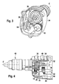
- FIG. 1 shows a section of a hand tool, namely a percussion drill, with a shift gear formed by a sliding gear 32 ( FIGS. 1 to 8 ).
- the sliding gear 32 is arranged in a gear housing 34 of the power tool and has a Doppelstirnrad 36 with two fixedly connected spur gears, which have different diameters and rotatably on a work spindle 38 and are mounted together displaceable in the direction of a Z-axis ( FIGS. 3, 4 and 7 ).
- the work spindle 38 is formed as a splined shaft and is directly connected rotationally fixed with a tool chuck 40 of the power tool.
- By a displacement of the double spur gear 36 in the direction of the Z-axis of the spur gears of the same can be coupled to an intermediate shaft 42 rotatably mounted gears 44, 46 ( FIGS. 3, 4 and 6 ).
- the handheld power tool has a handheld power tool switching unit with a rotary toggle unit 10, which has a rotationally drivable coupling unit 12 designed as an eccentric unit for coupling to a switching element 14 designed as an adjusting slide ( FIGS. 1, 2, 4 and 8 to 21).
- the coupling unit 12 has an output element 28 formed by an eccentric pin, which engages in a slot 70 of the switching element 14 ( FIGS. 4 and 8th ).
- the switching element 14 is formed by a bending plate part and engages with an integrally formed arm 48 between the two spur gears of the Doppelstirnrads 36.
- the hand tool machine switching unit comprises a formed by a leg spring energy storage element 16 which is provided for storing a switching energy in the case of preselection and in the rotary knob unit 10 is integrated.
- the coupling unit 12, the Energy storage element 16 and a handle unit 60 of the rotary knob unit 10 are parts of a common assembly.
- the rotary knob unit 10 is inserted into a recess 50 of the gear housing 34 in a plug-in direction 56 and is secured against the plug-in direction 56 via a latching connection 52 in a holding plate 54 arranged in the gear housing 34 ( Figures 2 . 3 and 5 ).
- the holding plate 54 has a U-shaped receiving area 58 into which the rotary toggle unit 10 is latched.
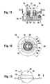
- the energy storage element 16 or the leg spring is arranged in the power flow between a first rotationally drivable shaft 18 of the coupling unit 12 and a second rotationally driven shaft 20 of the handle unit 60 of the rotary knob unit 10, wherein the leg spring to several 360 ° about the rotatably driven shafts 18, 20 extends ( Figures 10 . 11 . 12 . 15 to 21 ).
- the first formed as a hollow shaft shaft 18 of the coupling unit 12 is disposed in the second, also designed as a hollow shaft shaft 20 of the handle unit 60 and is rotatably supported by a molded journal 72 in a bearing bush 74 of the handle unit 60.
- the shafts 18, 20 each have a recess 22, 24 extending in the circumferential direction of the shafts 18, 20 over an angular range 26 of about 110 ° (see, in particular FIG. 12 ).
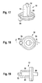
- the shaft 18 is formed integrally with the output element 28 designed as an eccentric pin and with the bearing journal 72 (cf., in particular, 17 to 21).
- the shaft 20 is integrally formed with an output element 30 of the handle unit 60, with a gripping surface forming a handle element (see, in particular FIG. 11 ).
- the leg spring is designed as a helical spring with a plurality of turns and has at one in the direction of a screw axis 62 of the leg spring, which substantially coincides with a rotational axis 64 of the rotary knob unit 10, first end a first radially inwardly projecting leg 66 and at one in the direction of the Schaubachse 62 second end of a second radially inwardly projecting leg 68 ( Figures 2 . 10 . 11, 12 . 15 and 16 ).
- the legs 66, 68 protrude in the radial direction inwardly through the recess 24 of the shaft 20 in the recess 22 of the shaft 18 and are biased to the recesses 22, 24 delimiting edges of the shafts 18, 20 at ( FIG. 12 ).
- the handle unit 60 Is rotated by an operator, the handle unit 60 from a first rotational position 82 or 84 for switching from one gear to another gear in a second rotational position 84 and 82 about the axis of rotation 64 by 180 ° and lies between the gears to be switched no tooth-on Tooth position, the eccentric pin of the coupling unit 12 is rotated in switching positions 76 and 78 and displaced by means of engaging in the slot 70 eccentric pin on a bearing axis 86 slidably mounted switching element 14 and switched to be switched gear ( FIGS. 1, 2 . 14 and 18 ).
- leg 66 or 68 interacts with stops 88, 90 of the handheld power tool switching unit after an angle of rotation of 110 ° of the angular range 26, parts of the leg spring being bridged in the force flow.
- the eccentric pin In the switching positions 76, 78, the eccentric pin is in gear shifts respectively along a pulse axis Z, along which an impulse of an unspecified striking mechanism of the power tool in operation acts on a tool inserted into the power tool insert, in a reversal position, whereby the leg spring along the Pulse axis Z is decoupled from vibrations.
- the leg spring is preloaded in the switch positions.
- the handle unit 60 is secured with an integrated, resiliently mounted locking pin 80 in the rotational positions 82, 84 in the circumferential direction by this is engaged in the switching positions 76, 78 in recesses of the gear housing 34.
Landscapes
- Engineering & Computer Science (AREA)
- Mechanical Engineering (AREA)
- Percussive Tools And Related Accessories (AREA)
- Transmission Devices (AREA)
- Soil Working Implements (AREA)
- Connection Of Motors, Electrical Generators, Mechanical Devices, And The Like (AREA)
- Structure Of Transmissions (AREA)
Description
- Die Erfindung geht aus von einer Handwerkzeugmaschinenschalteinheit nach dem Oberbegriff des Anspruchs 1.
- Aus der
EP 1 259 357 B1 ist eine Handwerkzeugmaschine mit einer solchen Handwerkzeugmaschinenschalteinheit mit einer Drehknebeleinheit bekannt, die eine von einem Zahnrad gebildete, drehend antreibbare Koppeleinheit zur Kopplung mit einem von einer Zahnstange gebildeten Schaltelement aufweist. Die Handwerkzeugmaschinenschalteinheit weist ein von einem Federstab gebildetes Energiespeicherelement auf, das zur Speicherung einer Schaltenergie im Falle einer Vorselektion vorgesehen ist. Das Energiespeicherelement ist zwischen der ersten Zahnstange und einer Schaltgabel angeordnet, die in eine Kupplung eines Ziehkeilgetriebes der Handwerkzeugmaschine eingreift. - Aus
EP 2 181 812 A2 , Stand der Technik gemäß Artikel 54(3) EPÜ, ist eine Handwerkzeugmaschinenschalteinheit mit einer Drehknebeleinheit bekannt die eine drehend antreibbare Koppeleinheit zur Kopplung mit wenigstens ei- nem Schaltelement aufweist, und mit wenigstens einem Energiespeicher- element, das zur Speicherung einer Schaltenergie im Falle einer Vorse- lektion vorgesehen ist und in der Drehknebeleinheit integriert ist, wobei das Energiespeicherelement zumindest eine Schenkelfeder aufweist, die sich um wenigstens 180° um zumindest eine drehend antreibbare Welle der Drehknebeleinheit erstreckt. - Die Erfindung geht aus von einer Handwerkzeugmaschinenschalteinheit mit einer Drehknebeleinheit, die eine drehend antreibbare Koppeleinheit zur Kopplung mit wenigstens einem Schaltelement aufweist, und mit wenigstens einem Energiespeicherelement, das zur Speicherung einer Schaltenergie im Falle einer Vorselektion vorgesehen ist.
- Es wird vorgesehen, dass das Energiespeicherelement in der Drehknebeleinheit integriert ist. Dabei soll unter "drehend antreibbaren Koppeleinheit der Drehknebeleinheit" insbesondere eine Einheit verstanden werden, die in zumindest einem Betriebsmodus zumindest teilweise und vorzugsweise vollständig um wenigstens eine Achse zum Schalten eines Getriebeganges, insbesondere von einem Bediener und/oder dem Energiespeicherelement, drehend angetrieben wird und dabei eine Drehbewegung um die Achse ausführt, wobei die Koppeleinheit insbesondere zur unmittelbaren Kontaktierung des Schaltelements vorgesehen ist. Vorzugsweise bildet die Koppeleinheit insbesondere auch einen Teil eines Getriebes, das dazu vorgesehen ist, eine Drehbewegung in eine andersartige Bewegung, insbesondere in eine translatorische Schaltbewegung, zu wandeln. Unter "vorgesehen" soll speziell ausgestattet und/oder ausgelegt verstanden werden. Unter einer "Vorselektion" soll insbesondere verstanden werden, dass ein Bediener einen Getriebegang in einem Auswahlvorgang auswählen kann, und der Getriebegang, insbesondere zeitversetzt, insbesondere zumindest teilweise selbsttätig, und zwar insbesondere, wenn eine Zahn-auf-Zahnstellung ausgehoben ist, in einem Schaltvorgang geschaltet wird. Unter einem "Energiespeicherelement" soll insbesondere ein Element verstanden werden, das gezielt dazu vorgesehen ist, Energie, insbesondere Bewegungsenergie während eines Auswahlvorgangs, in einer anderen Energieform, wie in einer Druckenergie, einer chemischen Energie und vorzugsweise in einer mechanischen Spannenergie, zu speichern und nach dem Auswahlvorgang bei einem Schaltvorgang wieder abzugeben. Ferner soll unter "integriert" insbesondere verstanden werden, dass das Energiespeicherelement im Kraftfluss zwischen zwei Elementen der Drehknebeleinheit angeordnet ist, und zwar vorzugsweise zwischen einem Griffelement der Drehknebeleinheit und der Koppeleinheit und/oder insbesondere zumindest teilweise innerhalb eines Griffelements der Drehknebeleinheit angeordnet ist. Durch eine entsprechende Ausgestaltung kann eine einfache, kompakte Bauweise erreicht werden. Ferner können Bauteile und Gewicht eingespart und der Montageaufwand reduziert werden.
- Das Energiespeicherelement kann von verschiedenen, dem Fachmann als sinnvoll erscheinenden Elementen gebildet sein, wie von einem Gasdruckspeicher, einem hydraulischen Druckspeicher usw., jedoch Zumindest von einem mechanischen Federelement, das dazu ausgelegt ist, be einem Auswahlvorgang elastisch ausgelenkt zu werden. Das Energiespeicherelement weist dabei zumindest eine Schenkelfeder auf oder ist als Schenkelfeder ausgebildet. Dabei soll unter einer "Schenkelfeder" insbesondere eine Feder verstanden werden, die zumindest einen Schenkel aufweist, der dazu vorgesehen ist, in Umfangsrichtung einer Drehbewegung, insbesondere um eine Schraubachse einer Schraubenfeder, ausgelenkt zu werden bzw. bei einem Auswahlvorgang ausgelenkt wird. Eine entsprechende Feder kann besonders Platz sparend integriert werden und insbesondere kann eine große elastische Auslenkung und damit ein großer Schaltweg nach einem Auswahlvorgang einfach realisiert werden, und zwar insbesondere, weil sich die Schenkelfeder um wenigstens 180° und besonders vorzugsweise um mehr als 360° um zumindest eine drehend antreibbare Welle der Drehknebeleinheit erstreckt.
- Ist das Energiespeicherelement im Kraftfluss zwischen einer ersten drehend antreibbaren Welle der Drehknebeleinheit und einer zweiten drehend antreibbaren Welle der Drehknebeleinheit angeordnet, kann wiederum vorteilhaft Bauraum eingespart werden, und zwar insbesondere, wenn die erste Welle zumindest teilweise in der zweiten Welle angeordnet ist, wodurch zudem eine vorteilhafte Lagerung erreicht werden kann.
- In einer weiteren Ausgestaltung der Erfindung wird vorgeschlagen, dass zumindest eine der Wellen eine Ausnehmung aufweist, die sich in Umfangsrichtung der Welle über einen Winkelbereich größer als 30° und vorzugsweise größer als 60° erstreckt, wodurch eine vorteilhaft einfache Kopplung des Energiespeicherelements mit der Welle erreicht werden kann, und zwar besonders bevorzugt bei einer Ausgestaltung des Energiespeicherelements als Schenkelfeder.
- Ferner wird vorgeschlagen, dass zumindest eine der Wellen einstückig mit einem Ausgangselement der Drehknebeleinheit ausgebildet ist. Dabei soll unter einem Ausgangselement insbesondere ein Element der Koppeleinheit verstanden werden, das direkt mit einem angrenzenden Schaltelement gekoppelt, d.h. kontaktiert ist, und/oder ein Element, das dazu vorgesehen ist, von einem Bediener bei einem Auswahlvorgang direkt kontaktiert zu werden, wie insbesondere ein Griffelement der Drehknebeleinheit. Durch eine entsprechende Ausgestaltung können zusätzliche Bauteile, Gewicht, Montageaufwand und Kosten eingespart werden.
- Weist das Energiespeicherelement wenigstens ein in einer Schaltstellung vorgespanntes Federelement auf, können unerwünschte Bewegungen und insbesondere Schwingungsanregungen vorteilhaft verhindert werden und es können insbesondere die Koppeleinheit und eine Griffeinheit zueinander präzise in einer eindeutigen Stellung positioniert werden. Dabei soll unter einer "Schaltstellung" insbesondere eine Stellung verstanden werden, bei der ein Getriebegang geschaltet ist. Vorzugsweise ist dabei eine Betriebsfrequenz einer die Handwerkzeugmaschinenschaltvorrichtung umfassenden Handwerkzeugmaschine kleiner als eine Eigenfrequenz des Federelements.
- Die Koppeleinheit weist Zumindest ein Exzenterelement auf und kann verschiedene, dem Fachmann als sinnvoll erscheinende Elemente aufweisen, wie beispielsweise auch ein Zahnrad , wodurch ein konstruktiv einfaches Getriebe zur Wandlung einer Drehbewegung in eine axiale Schaltbewegung erreicht werden kann. Ferner kann in zumindest einzelne Richtungen eine vorteilhafte Schwingungsentkopplung des Energiespeicherelements erreicht werden. Vorzugsweise ist ein Exzenterelement bei einer Handwerkzeugmaschine mit einer Schlageinheit, wie bei einer Schlagbohrmaschine, einem Bohr- und/oder Meißelhammer, in zumindest einer Schaltstellung entlang einer Impulsachse, entlang welcher ein Impuls auf ein in die Handwerkzeugmaschine eingesetztes Einsatzwerkzeug wirkt, in einer Umkehrstellung angeordnet, wodurch die Energiespeichereinheit besonders vorteilhaft entlang der Impulsachse von Schwingungen entkoppelt werden kann.
- Weist die Handwerkzeugmaschinenschalteinheit wenigstens einen mechanischen Anschlag zum Antrieb der Koppeleinheit auf, kann eine sichere Bewegung der Koppeleinheit gewährleistet werden, auch wenn eine Antriebskraft über einen bestimmten Betrag ansteigt, wie beispielsweise bei einem Verklemmen. Der Anschlag ist dabei vorzugsweise in der Weise ausgestaltet, dass das Energiespeicherelement zumindest teilweise überbrückt werden kann, d.h. dass zumindest ein Teil des Energiespeicherelements vom Kraftfluss bei Anlage des Anschlags ausgenommen wird.
- Die erfindungsgemäße Handwerkzeugmaschinenschalteinheit gemäß Anspruch 1 stellt eine Alternative zur bekannten Handwerkzlugmaschinen schalteinheiten vor und kann bei verschiedenen, dem Fachmann als sinnvoll erscheinenden Handwerkzeugmaschinen eingesetzt werden, jedoch besonders vorteilhaft bei Handwerkzeugmaschinen, die ein Schieberadgetriebe aufweisen, und zwar insbesondere aufgrund der Platz sparenden Integrationsmöglichkeit und/oder des einfach realisierbaren großen Schaltwegs nach einem Auswahlvorgang. Dabei soll unter einem "Schieberadgetriebe" insbesondere ein Getriebe verstanden werden, bei dem ein Zahnrad, insbesondere ein Stirnzahnrad, bei einem Schaltvorgang verschoben wird.
- Weitere Vorteile ergeben sich aus der folgenden Zeichnungsbeschreibung. In der Zeichnung ist ein Ausführungsbeispiel der Erfindung dargestellt. Die Zeichnung, die Beschreibung und die Ansprüche enthalten zahlreiche Merkmale in Kombination. Der Fachmann wird die Merkmale zweckmäßigerweise auch einzeln betrachten und zu sinnvollen weiteren Kombinationen zusammenfassen.
- Es zeigen:
- Fig. 1
- einen Ausschnitt einer Handwerkzeugmaschine,
- Fig. 2
- einen Schnitt entlang der Linie II-II in
Figur 1 , - Fig. 3
- eine räumliche Ansicht in ein Getriebegehäuse der Handwerkzeugmaschine,
- Fig. 4
- eine Seitenansicht der Handwerkzeugmaschine mit teilweise ausgeblendetem Getriebegehäuse,
- Fig. 5
- eine Halteplatte in einer Einzeldarstellung,
- Fig. 6
- eine Zwischenwelle mit Zahnrädern in einer Einzeldarstellung,
- Fig. 7
- ein Doppelstirnrad in einer Einzeldarstellung,
- Fig. 8
- einen Verstellschieber in einer Einzeldarstellung,
- Fig. 9
- eine Drehknebeleinheit der Handwerkzeugmaschine in einer Seitenansicht,
- Fig. 10
- eine Explosionsdarstellung der Drehknebeleinheit,
- Fig. 11
- eine Schnittdarstellung der Drehknebeleinheit entlang der Linie II-II in
Figur 1 , - Fig. 12
- einen Schnitt entlang der Linie XII-XII in
Figur 11 , - Fig. 13
- eine Draufsicht der Drehknebeleinheit mit dem Verstellschieber und einer Lagerachse,
- Fig. 14
- die Einheit aus
Figur 13 in einer um eine Z-Achse um 90° gedrehten Stellung, - Fig. 15
- ein von einer Schenkelfeder gebildetes Energiespeicherelement in einer Seitenansicht,
- Fig. 16
- die Schenkelfeder in einer Draufsicht
- Fig. 17
- eine Koppeleinheit der Drehknebeleinheit in einer räumlichen Darstellung,
- Fig. 18
- die Koppeleinheit in einer ersten Draufsicht,
- Fig. 19
- die Koppeleinheit in einer ersten Seitenansicht,
- Fig. 20
- die Koppeleinheit in einer zweiten Draufsicht und
- Fig. 21
- die Koppeleinheit in einer zweiten Seitenansicht.
-
Figur 1 zeigt einen Ausschnitt einer Handwerkzeugmaschine, und zwar einer Schlagbohrmaschine, mit einem von einem Schieberadgetriebe 32 gebildeten Schaltgetriebe (Figuren 1 bis 8 ). Das Schieberadgetriebe 32 ist in einem Getriebegehäuse 34 der Handwerkzeugmaschine angeordnet und weist ein Doppelstirnrad 36 mit zwei fest miteinander verbundenen Stirnrädern auf, die unterschiedliche Durchmesser aufweisen und auf einer Arbeitsspindel 38 drehfest und in Richtung einer Z-Achse gemeinsam verschiebbar gelagert sind (Figuren 3, 4 und7 ). Die Arbeitsspindel 38 ist als Keilwelle ausgebildet und ist unmittelbar drehfest mit einem Werkzeugfutter 40 der Handwerkzeugmaschine verbunden. Durch eine Verschiebung des Doppelstirnrads 36 in Richtung der Z-Achse können die Stirnräder desselben mit auf einer Zwischenwelle 42 drehfest gelagerten Zahnrädern 44, 46 gekoppelt werden (Figuren 3, 4 und6 ). - Zur Durchführung eines Schaltvorgangs weist die Handwerkzeugmaschine eine Handwerkzeugmaschinenschalteinheit mit einer Drehknebeleinheit 10 auf, die eine drehend antreibbare, als Exzentereinheit ausgebildete Koppeleinheit 12 zur Kopplung mit einem als Verstellschieber ausgebildeten Schaltelement 14 aufweist (
Figuren 1, 2, 4 sowie 8 bis 21). Die Koppeleinheit 12 weist ein von einem Exzenterzapfen gebildetes Ausgangselement 28 auf, das in ein Langloch 70 des Schaltelements 14 eingreift (Figuren 4 und8 ). Das Schaltelement 14 ist von einem Biegeblechteil gebildet und greift mit einem angeformten Arm 48 zwischen die beiden Stirnräder des Doppelstirnrads 36. Ferner weist die Handwerkzeugmaschinenschalteinheit ein von einer Schenkelfeder gebildetes Energiespeicherelement 16 auf, das zur Speicherung einer Schaltenergie im Falle einer Vorselektion vorgesehen ist und das in der Drehknebeleinheit 10 integriert ist. Die Koppeleinheit 12, das Energiespeicherelement 16 und eine Griffeinheit 60 der Drehknebeleinheit 10 sind Teile einer gemeinsamen Baugruppe. - Die Drehknebeleinheit 10 ist in eine Ausnehmung 50 des Getriebegehäuses 34 in eine Einsteckrichtung 56 eingesteckt und ist über eine Rastverbindung 52 in einer im Getriebegehäuse 34 angeordneten Halteplatte 54 entgegen der Einsteckrichtung 56 gesichert (
Figuren 2 ,3 und5 ). Die Halteplatte 54 weist hierfür einen U-förmigen Aufnahmebereich 58 auf, in den die Drehknebeleinheit 10 eingerastet ist. - Das Energiespeicherelement 16 bzw. die Schenkelfeder ist im Kraftfluss zwischen einer ersten drehend antreibbaren Welle 18 der Koppeleinheit 12 und einer zweiten drehend antreibbaren Welle 20 der Griffeinheit 60 der Drehknebeleinheit 10 angeordnet, wobei sich die Schenkelfeder um mehrere 360° um die drehend antreibbaren Wellen 18, 20 erstreckt (
Figuren 10 ,11 ,12 ,15 bis 21 ). Die erste als Hohlwelle ausgebildete Welle 18 der Koppeleinheit 12 ist in der zweiten, ebenfalls als Hohlwelle ausgebildeten Welle 20 der Griffeinheit 60 angeordnet und ist mittels eines angeformten Lagerzapfens 72 in einer Lagerbuchse 74 der Griffeinheit 60 drehbar gelagert. Die Wellen 18, 20 weisen jeweils eine Ausnehmung 22, 24 auf, die sich in Umfangsrichtung der Wellen 18, 20 über einen Winkelbereich 26 von ca. 110° erstrecken (vgl. insbesondereFigur 12 ). Die Welle 18 ist einstückig mit dem als Exzenterzapfen ausgebildeten Ausgangselement 28 und mit dem Lagerzapfen 72 ausgebildet (vgl. insbesondere 17 bis 21). Die Welle 20 ist einstückig mit einem Ausgangselement 30 der Griffeinheit 60 ausgebildet, und zwar mit einem eine Grifffläche bildenden Griffelement (vgl. insbesondereFigur 11 ). - Die Schenkelfeder ist als Schraubenfeder mit mehreren Windungen ausgeführt und weist an einem in Richtung einer Schraubachse 62 der Schenkelfeder, die im Wesentlichen mit einer Drehachse 64 der Drehknebeleinheit 10 übereinstimmt, ersten Ende einen ersten radial nach innen ragenden Schenkel 66 und an einem in Richtung der Schaubachse 62 zweiten Ende einen zweiten radial nach innen ragenden Schenkel 68 auf (
Figuren 2 ,10 ,11, 12 ,15 und 16 ). Im montierten Zustand ragen die Schenkel 66, 68 in radialer Richtung nach innen durch die Ausnehmung 24 der Welle 20 in die Ausnehmung 22 der Welle 18 und liegen vorgespannt an die Ausnehmungen 22, 24 begrenzenden Ränder der Wellen 18, 20 an (Figur 12 ). - Wird von einem Bediener die Griffeinheit 60 von einer ersten Drehstellung 82 oder 84 zum Schalten von einem Getriebegang in einen anderen Getriebegang in eine zweite Drehstellung 84 bzw. 82 um die Drehachse 64 um 180° gedreht und liegt zwischen den zu schaltenden Stirnrädern keine Zahn-auf-Zahnstellung vor, wird der Exzenterzapfen der Koppeleinheit 12 in Schaltstellungen 76 bzw. 78 gedreht und mittels des in das Langloch 70 eingreifenden Exzenterzapfens das auf einer Lagerachse 86 verschiebbar gelagerte Schaltelement 14 verschoben und der zu schaltende Getriebegang geschaltet (
Figuren 1, 2 ,14 und18 ). Übersteigt eine erforderliche Schaltkraft eine von der Schenkelfeder aufbringbare Kraft, wirkt der Schenkel 66 bzw. 68 nach einem Verdrehwinkel von 110° des Winkelbereichs 26 mit Anschlägen 88, 90 der Handwerkzeugmaschinenschalteinheit zusammen, wobei Teile der Schenkelfeder im Kraftfluss überbrückt werden. - In den Schaltstellungen 76, 78 befindet sich der Exzenterzapfen bei geschalteten Getriebegängen jeweils entlang einer Impulsachse Z, entlang welcher im Betrieb ein Impuls eines nicht näher darstellten Schlagwerks der Handwerkzeugmaschine auf ein in die Handwerkzeugmaschine eingesetztes Einsatzwerkzeug wirkt, in einer Umkehrstellung, wodurch die Schenkelfeder entlang der Impulsachse Z von Schwingungen entkoppelt ist. Die Schenkelfeder ist in den Schaltstellungen vorgespannt. Die Griffeinheit 60 ist mit einem integrierten, federnd gelagerten Rastbolzen 80 in den Drehstellungen 82, 84 in Umfangsrichtung gesichert, indem dieser in den Schaltstellungen 76, 78 in Ausnehmungen des Getriebegehäuses 34 eingerastet ist.
- Wird von einem Bediener die Griffeinheit 60 von der Drehstellung 82 oder 84 zum Schalten von einem Getriebegang in einen anderen Getriebegang in die andere Drehstellung 84 bzw. 82 um die Drehachse 64 um 180° gedreht und liegt zwischen den zu schaltenden Stirnrädern eine Zahn-auf-Zahnstellung vor, werden die Griffeinheit 60 und die Koppeleinheit 12 und somit auch die Wellen 18, 20 gegeneinander verdreht und die Schenkelfeder wird weiter vorgespannt. Löst sich die Zahn-auf-Zahnstellung auf, wird mittels der in der Schenkelfeder gespeicherten Spannenergie der vorgewählte Getriebegang geschaltet, indem mittels der Spannenergie der Schenkelfeder die Koppeleinheit 12 bzw. der Exzenterzapfen in seine Schaltstellung 76 bzw. 78 gedreht, das Schaltelement 14 verschoben und der entsprechende Getriebegang geschaltet wird.
Claims (9)
- Handwerkzeugmaschinenschalteinheit mit einer Drehknebeleinheit (10), die eine drehend antreibbare Koppeleinheit (12) zur Kopplung mit wenigstens einem Schaltelement (14) aufweist, und mit wenigstens einem Energiespeicherelement (16), das zur Speicherung einer Schaltenergie im Falle einer Vorselektion vorgesehen ist und in der Drehknebeleinheit (10) integriert ist, dadurch gekennzeichnet, dass das Energiespeicherelement (16) zumindest eine Schenkelfeder aufweist, die sich um wenigstens 180° um zumindest eine drehend antreibbare Welle (18, 20) der Drehknebeleinheit (10) erstreckt, und die Koppeleinheit (12) zumindest eine Exzentereinheit (28) aufweist.
- Handwerkzeugmaschinenschalteinheit nach einem der vorhergehenden Ansprüche, dadurch gekennzeichnet, dass das Energiespeicherelement (16) im Kraftfluss zwischen einer ersten drehend antreibbaren Welle (18) der Drehknebeleinheit (10) und einer zweiten drehend antreibbaren Welle (20) der Drehknebeleinheit (10) angeordnet ist.
- Handwerkzeugmaschinenschalteinheit nach Anspruch 2, dadurch gekennzeichnet, dass die erste Welle (18) zumindest teilweise in der zweiten Welle (20) angeordnet ist.
- Handwerkzeugmaschinenschalteinheit nach Anspruch 2 oder 3, dadurch gekennzeichnet, dass zumindest eine der Wellen (18, 20) eine Ausnehmung (22, 24) aufweist, die sich in Umfangsrichtung der Welle (18, 20) über einen Winkelbereich (26) größer als 30° erstreckt.
- Handwerkzeugmaschinenschalteinheit nach einem der Anspruch 2 bis 4, dadurch gekennzeichnet, dass zumindest eine der Wellen (18, 20) einstückig mit einem Ausgangselement (28, 30) der Drehknebeleinheit (10) ausgebildet ist.
- Handwerkzeugmaschinenschalteinheit nach einem der vorhergehenden Ansprüche, dadurch gekennzeichnet, dass das Energiespeicherelement (16) wenigstens ein in einer Schaltstellung (76, 78) vorgespanntes Federelement aufweist.
- Handwerkzeugmaschinenschalteinheit nach einem der vorhergehenden Ansprüche, gekennzeichnet durch wenigstens einen mechanischen Anschlag (88, 90) zum Antrieb der Koppeleinheit (12).
- Handwerkzeugmaschine mit einer Handwerkzeugmaschinenschalteinheit nach einem der vorhergehenden Ansprüche.
- Handwerkzeugmaschine nach Anspruch 8, gekennzeichnet durch ein Schieberadgetriebe (32).
Applications Claiming Priority (2)
| Application Number | Priority Date | Filing Date | Title |
|---|---|---|---|
| DE102009028622A DE102009028622A1 (de) | 2009-08-18 | 2009-08-18 | Handwerkzeugmaschinenschalteinheit |
| PCT/EP2010/059601 WO2011020644A1 (de) | 2009-08-18 | 2010-07-06 | Handwerkzeugmaschinenschalteinheit |
Publications (2)
| Publication Number | Publication Date |
|---|---|
| EP2467238A1 EP2467238A1 (de) | 2012-06-27 |
| EP2467238B1 true EP2467238B1 (de) | 2013-05-01 |
Family
ID=42536346
Family Applications (1)
| Application Number | Title | Priority Date | Filing Date |
|---|---|---|---|
| EP10732339.6A Active EP2467238B1 (de) | 2009-08-18 | 2010-07-06 | Handwerkzeugmaschinenschalteinheit |
Country Status (6)
| Country | Link |
|---|---|
| US (1) | US9643309B2 (de) |
| EP (1) | EP2467238B1 (de) |
| CN (1) | CN102481688B (de) |
| DE (1) | DE102009028622A1 (de) |
| RU (1) | RU2550462C2 (de) |
| WO (1) | WO2011020644A1 (de) |
Families Citing this family (11)
| Publication number | Priority date | Publication date | Assignee | Title |
|---|---|---|---|---|
| CN101758486B (zh) * | 2010-01-21 | 2011-09-28 | 浙江海王电器有限公司 | 轻型单钮多功能电锤 |
| CN201848770U (zh) * | 2010-09-20 | 2011-06-01 | 胡继宁 | 具有安全换挡装置的手持式电动工具 |
| DE102012202278A1 (de) | 2012-02-15 | 2013-08-22 | Hilti Aktiengesellschaft | Handwerkzeugmaschine |
| CN102837296A (zh) * | 2012-10-02 | 2012-12-26 | 浙江奔宇工具有限公司 | 电锤的拨档装置 |
| WO2016196899A1 (en) | 2015-06-05 | 2016-12-08 | Ingersoll-Rand Company | Power tool housings |
| WO2016196918A1 (en) | 2015-06-05 | 2016-12-08 | Ingersoll-Rand Company | Power tool user interfaces |
| WO2016196979A1 (en) | 2015-06-05 | 2016-12-08 | Ingersoll-Rand Company | Impact tools with ring gear alignment features |
| WO2016196891A1 (en) * | 2015-06-05 | 2016-12-08 | Ingersoll-Rand Company | Power tool user interfaces |
| WO2016196984A1 (en) | 2015-06-05 | 2016-12-08 | Ingersoll-Rand Company | Power tools with user-selectable operational modes |
| US11261964B2 (en) * | 2018-05-17 | 2022-03-01 | Black & Decker Inc. | Compliant shifting mechanism and multi-speed power tool having same |
| DE102020213232A1 (de) * | 2020-10-20 | 2022-04-21 | Robert Bosch Gesellschaft mit beschränkter Haftung | Handwerkzeugmaschine mit mindestens einer Betätigungseinheit |
Family Cites Families (11)
| Publication number | Priority date | Publication date | Assignee | Title |
|---|---|---|---|---|
| DE4000822A1 (de) | 1990-01-13 | 1991-07-18 | Bosch Gmbh Robert | Elektrisch betriebene handwerkzeugmaschine |
| BG51906A1 (en) * | 1992-02-11 | 1993-11-15 | Ganchev | Device for commutation the revolutions of a hand electrical two-speed drilling machine |
| WO1996015863A1 (en) | 1994-11-22 | 1996-05-30 | United Technologies Corporation | Cleaning method for turbine airfoils by ultrasonics |
| GB9621202D0 (en) * | 1996-10-11 | 1996-11-27 | Black & Decker Inc | Mode change switch |
| RU2174895C2 (ru) * | 1999-12-01 | 2001-10-20 | Колган Юрий Никитович | Ручная машина |
| DE10007665A1 (de) * | 2000-02-19 | 2001-09-06 | Scintilla Ag | Werkzeugmaschine |
| DE102004058175B4 (de) | 2004-12-02 | 2019-10-31 | Robert Bosch Gmbh | Handwerkzeugmaschine mit anatomisch verbessertem Schaltelement |
| JP4812471B2 (ja) * | 2006-03-09 | 2011-11-09 | 株式会社マキタ | 作業工具 |
| DE102007009986A1 (de) * | 2007-03-02 | 2008-09-04 | Robert Bosch Gmbh | Handwerkzeugmaschine |
| US8251156B2 (en) * | 2008-10-30 | 2012-08-28 | Black & Decker Inc. | Compliant shifting mechanism for right angle drill |
| DE102008054786A1 (de) * | 2008-12-17 | 2010-07-01 | Hilti Aktiengesellschaft | Drehschalter |
-
2009
- 2009-08-18 DE DE102009028622A patent/DE102009028622A1/de not_active Withdrawn
-
2010
- 2010-07-06 RU RU2012110120/02A patent/RU2550462C2/ru active
- 2010-07-06 US US13/390,467 patent/US9643309B2/en active Active
- 2010-07-06 EP EP10732339.6A patent/EP2467238B1/de active Active
- 2010-07-06 WO PCT/EP2010/059601 patent/WO2011020644A1/de not_active Ceased
- 2010-07-06 CN CN201080036610.7A patent/CN102481688B/zh active Active
Also Published As
| Publication number | Publication date |
|---|---|
| DE102009028622A1 (de) | 2011-02-24 |
| WO2011020644A1 (de) | 2011-02-24 |
| EP2467238A1 (de) | 2012-06-27 |
| US20120234568A1 (en) | 2012-09-20 |
| US9643309B2 (en) | 2017-05-09 |
| RU2012110120A (ru) | 2013-09-27 |
| RU2550462C2 (ru) | 2015-05-10 |
| CN102481688A (zh) | 2012-05-30 |
| CN102481688B (zh) | 2015-01-28 |
Similar Documents
| Publication | Publication Date | Title |
|---|---|---|
| EP2467238B1 (de) | Handwerkzeugmaschinenschalteinheit | |
| DE102009054930B4 (de) | Bohrmaschine | |
| EP2129496B1 (de) | Handwerkzeugmaschine | |
| DE102009054927B4 (de) | Handwerkzeugmaschine, insbesondere Akkuhandwerkzeugmaschine | |
| DE102011078082B4 (de) | Handwerkzeugmaschine, insbesondere Bohr- oder Schraubgerät | |
| EP0373106B1 (de) | Handwerkzeug mit Schaltgetriebe | |
| DE202009000793U1 (de) | Angetriebenes Werkzeug | |
| WO2010023027A1 (de) | Werkzeugmaschinengetriebevorrichtung | |
| EP2342050B1 (de) | Handwerkzeugmaschine mit einem schaltbaren getriebe | |
| EP1259357B1 (de) | Werkzeugmaschine | |
| DE10312980A1 (de) | Elektrohandwerkzeugmaschine | |
| DE102012202278A1 (de) | Handwerkzeugmaschine | |
| WO2012156120A1 (de) | Werkzeugaufnahme | |
| EP2655018A1 (de) | Handwerkzeugmaschine | |
| DE102011075858A1 (de) | Werkzeugaufnahme | |
| DE102007010180A1 (de) | Handwerkzeugmaschine | |
| DE102004055236A1 (de) | Handwerkzeugmaschine mit wählbaren Betriebarten | |
| DE102010064369B4 (de) | Handwerkzeugmaschinenspannvorrichtung | |
| DE102010064371B4 (de) | Handwerkzeugmaschinenspannvorrichtung mit Schaltelement | |
| DE102016224577A1 (de) | Handwerkzeugmaschine | |
| EP2104594B1 (de) | Handwerkzeugmaschine | |
| WO2016150659A1 (de) | Handwerkzeugmaschine | |
| DE102007010183A1 (de) | Handwerkzeugmaschine | |
| EP1127644B1 (de) | Elektrohandwerkzeug | |
| EP2121247A1 (de) | Handwerkzeugmaschinenschaltvorrichtung |
Legal Events
| Date | Code | Title | Description |
|---|---|---|---|
| PUAI | Public reference made under article 153(3) epc to a published international application that has entered the european phase |
Free format text: ORIGINAL CODE: 0009012 |
|
| 17P | Request for examination filed |
Effective date: 20120319 |
|
| AK | Designated contracting states |
Kind code of ref document: A1 Designated state(s): AL AT BE BG CH CY CZ DE DK EE ES FI FR GB GR HR HU IE IS IT LI LT LU LV MC MK MT NL NO PL PT RO SE SI SK SM TR |
|
| DAX | Request for extension of the european patent (deleted) | ||
| GRAP | Despatch of communication of intention to grant a patent |
Free format text: ORIGINAL CODE: EPIDOSNIGR1 |
|
| GRAS | Grant fee paid |
Free format text: ORIGINAL CODE: EPIDOSNIGR3 |
|
| GRAA | (expected) grant |
Free format text: ORIGINAL CODE: 0009210 |
|
| AK | Designated contracting states |
Kind code of ref document: B1 Designated state(s): AL AT BE BG CH CY CZ DE DK EE ES FI FR GB GR HR HU IE IS IT LI LT LU LV MC MK MT NL NO PL PT RO SE SI SK SM TR |
|
| REG | Reference to a national code |
Ref country code: GB Ref legal event code: FG4D Free format text: NOT ENGLISH |
|
| REG | Reference to a national code |
Ref country code: CH Ref legal event code: EP Ref country code: AT Ref legal event code: REF Ref document number: 609597 Country of ref document: AT Kind code of ref document: T Effective date: 20130515 |
|
| REG | Reference to a national code |
Ref country code: IE Ref legal event code: FG4D Free format text: LANGUAGE OF EP DOCUMENT: GERMAN |
|
| REG | Reference to a national code |
Ref country code: DE Ref legal event code: R096 Ref document number: 502010003201 Country of ref document: DE Effective date: 20130627 |
|
| REG | Reference to a national code |
Ref country code: NL Ref legal event code: VDEP Effective date: 20130501 |
|
| REG | Reference to a national code |
Ref country code: LT Ref legal event code: MG4D |
|
| PG25 | Lapsed in a contracting state [announced via postgrant information from national office to epo] |
Ref country code: SE Free format text: LAPSE BECAUSE OF FAILURE TO SUBMIT A TRANSLATION OF THE DESCRIPTION OR TO PAY THE FEE WITHIN THE PRESCRIBED TIME-LIMIT Effective date: 20130501 Ref country code: IS Free format text: LAPSE BECAUSE OF FAILURE TO SUBMIT A TRANSLATION OF THE DESCRIPTION OR TO PAY THE FEE WITHIN THE PRESCRIBED TIME-LIMIT Effective date: 20130901 Ref country code: LT Free format text: LAPSE BECAUSE OF FAILURE TO SUBMIT A TRANSLATION OF THE DESCRIPTION OR TO PAY THE FEE WITHIN THE PRESCRIBED TIME-LIMIT Effective date: 20130501 Ref country code: ES Free format text: LAPSE BECAUSE OF FAILURE TO SUBMIT A TRANSLATION OF THE DESCRIPTION OR TO PAY THE FEE WITHIN THE PRESCRIBED TIME-LIMIT Effective date: 20130812 Ref country code: FI Free format text: LAPSE BECAUSE OF FAILURE TO SUBMIT A TRANSLATION OF THE DESCRIPTION OR TO PAY THE FEE WITHIN THE PRESCRIBED TIME-LIMIT Effective date: 20130501 Ref country code: SI Free format text: LAPSE BECAUSE OF FAILURE TO SUBMIT A TRANSLATION OF THE DESCRIPTION OR TO PAY THE FEE WITHIN THE PRESCRIBED TIME-LIMIT Effective date: 20130501 Ref country code: PT Free format text: LAPSE BECAUSE OF FAILURE TO SUBMIT A TRANSLATION OF THE DESCRIPTION OR TO PAY THE FEE WITHIN THE PRESCRIBED TIME-LIMIT Effective date: 20130902 Ref country code: GR Free format text: LAPSE BECAUSE OF FAILURE TO SUBMIT A TRANSLATION OF THE DESCRIPTION OR TO PAY THE FEE WITHIN THE PRESCRIBED TIME-LIMIT Effective date: 20130802 Ref country code: NO Free format text: LAPSE BECAUSE OF FAILURE TO SUBMIT A TRANSLATION OF THE DESCRIPTION OR TO PAY THE FEE WITHIN THE PRESCRIBED TIME-LIMIT Effective date: 20130801 |
|
| PG25 | Lapsed in a contracting state [announced via postgrant information from national office to epo] |
Ref country code: HR Free format text: LAPSE BECAUSE OF FAILURE TO SUBMIT A TRANSLATION OF THE DESCRIPTION OR TO PAY THE FEE WITHIN THE PRESCRIBED TIME-LIMIT Effective date: 20130501 Ref country code: CY Free format text: LAPSE BECAUSE OF FAILURE TO SUBMIT A TRANSLATION OF THE DESCRIPTION OR TO PAY THE FEE WITHIN THE PRESCRIBED TIME-LIMIT Effective date: 20130501 Ref country code: BG Free format text: LAPSE BECAUSE OF FAILURE TO SUBMIT A TRANSLATION OF THE DESCRIPTION OR TO PAY THE FEE WITHIN THE PRESCRIBED TIME-LIMIT Effective date: 20130801 Ref country code: PL Free format text: LAPSE BECAUSE OF FAILURE TO SUBMIT A TRANSLATION OF THE DESCRIPTION OR TO PAY THE FEE WITHIN THE PRESCRIBED TIME-LIMIT Effective date: 20130501 |
|
| PG25 | Lapsed in a contracting state [announced via postgrant information from national office to epo] |
Ref country code: LV Free format text: LAPSE BECAUSE OF FAILURE TO SUBMIT A TRANSLATION OF THE DESCRIPTION OR TO PAY THE FEE WITHIN THE PRESCRIBED TIME-LIMIT Effective date: 20130501 |
|
| BERE | Be: lapsed |
Owner name: ROBERT BOSCH G.M.B.H. Effective date: 20130731 |
|
| PG25 | Lapsed in a contracting state [announced via postgrant information from national office to epo] |
Ref country code: EE Free format text: LAPSE BECAUSE OF FAILURE TO SUBMIT A TRANSLATION OF THE DESCRIPTION OR TO PAY THE FEE WITHIN THE PRESCRIBED TIME-LIMIT Effective date: 20130501 Ref country code: CZ Free format text: LAPSE BECAUSE OF FAILURE TO SUBMIT A TRANSLATION OF THE DESCRIPTION OR TO PAY THE FEE WITHIN THE PRESCRIBED TIME-LIMIT Effective date: 20130501 Ref country code: SK Free format text: LAPSE BECAUSE OF FAILURE TO SUBMIT A TRANSLATION OF THE DESCRIPTION OR TO PAY THE FEE WITHIN THE PRESCRIBED TIME-LIMIT Effective date: 20130501 Ref country code: DK Free format text: LAPSE BECAUSE OF FAILURE TO SUBMIT A TRANSLATION OF THE DESCRIPTION OR TO PAY THE FEE WITHIN THE PRESCRIBED TIME-LIMIT Effective date: 20130501 |
|
| PG25 | Lapsed in a contracting state [announced via postgrant information from national office to epo] |
Ref country code: RO Free format text: LAPSE BECAUSE OF FAILURE TO SUBMIT A TRANSLATION OF THE DESCRIPTION OR TO PAY THE FEE WITHIN THE PRESCRIBED TIME-LIMIT Effective date: 20130501 Ref country code: MC Free format text: LAPSE BECAUSE OF FAILURE TO SUBMIT A TRANSLATION OF THE DESCRIPTION OR TO PAY THE FEE WITHIN THE PRESCRIBED TIME-LIMIT Effective date: 20130501 Ref country code: NL Free format text: LAPSE BECAUSE OF FAILURE TO SUBMIT A TRANSLATION OF THE DESCRIPTION OR TO PAY THE FEE WITHIN THE PRESCRIBED TIME-LIMIT Effective date: 20130501 Ref country code: IT Free format text: LAPSE BECAUSE OF FAILURE TO SUBMIT A TRANSLATION OF THE DESCRIPTION OR TO PAY THE FEE WITHIN THE PRESCRIBED TIME-LIMIT Effective date: 20130501 |
|
| PLBE | No opposition filed within time limit |
Free format text: ORIGINAL CODE: 0009261 |
|
| STAA | Information on the status of an ep patent application or granted ep patent |
Free format text: STATUS: NO OPPOSITION FILED WITHIN TIME LIMIT |
|
| 26N | No opposition filed |
Effective date: 20140204 |
|
| REG | Reference to a national code |
Ref country code: IE Ref legal event code: MM4A |
|
| REG | Reference to a national code |
Ref country code: FR Ref legal event code: ST Effective date: 20140331 |
|
| PG25 | Lapsed in a contracting state [announced via postgrant information from national office to epo] |
Ref country code: BE Free format text: LAPSE BECAUSE OF NON-PAYMENT OF DUE FEES Effective date: 20130731 |
|
| REG | Reference to a national code |
Ref country code: DE Ref legal event code: R097 Ref document number: 502010003201 Country of ref document: DE Effective date: 20140204 |
|
| PG25 | Lapsed in a contracting state [announced via postgrant information from national office to epo] |
Ref country code: FR Free format text: LAPSE BECAUSE OF NON-PAYMENT OF DUE FEES Effective date: 20130731 |
|
| PG25 | Lapsed in a contracting state [announced via postgrant information from national office to epo] |
Ref country code: IE Free format text: LAPSE BECAUSE OF NON-PAYMENT OF DUE FEES Effective date: 20130706 |
|
| PG25 | Lapsed in a contracting state [announced via postgrant information from national office to epo] |
Ref country code: SM Free format text: LAPSE BECAUSE OF FAILURE TO SUBMIT A TRANSLATION OF THE DESCRIPTION OR TO PAY THE FEE WITHIN THE PRESCRIBED TIME-LIMIT Effective date: 20130501 |
|
| PG25 | Lapsed in a contracting state [announced via postgrant information from national office to epo] |
Ref country code: MT Free format text: LAPSE BECAUSE OF FAILURE TO SUBMIT A TRANSLATION OF THE DESCRIPTION OR TO PAY THE FEE WITHIN THE PRESCRIBED TIME-LIMIT Effective date: 20130501 Ref country code: TR Free format text: LAPSE BECAUSE OF FAILURE TO SUBMIT A TRANSLATION OF THE DESCRIPTION OR TO PAY THE FEE WITHIN THE PRESCRIBED TIME-LIMIT Effective date: 20130501 |
|
| PG25 | Lapsed in a contracting state [announced via postgrant information from national office to epo] |
Ref country code: MK Free format text: LAPSE BECAUSE OF FAILURE TO SUBMIT A TRANSLATION OF THE DESCRIPTION OR TO PAY THE FEE WITHIN THE PRESCRIBED TIME-LIMIT Effective date: 20130501 Ref country code: LU Free format text: LAPSE BECAUSE OF NON-PAYMENT OF DUE FEES Effective date: 20130706 Ref country code: HU Free format text: LAPSE BECAUSE OF FAILURE TO SUBMIT A TRANSLATION OF THE DESCRIPTION OR TO PAY THE FEE WITHIN THE PRESCRIBED TIME-LIMIT; INVALID AB INITIO Effective date: 20100706 |
|
| REG | Reference to a national code |
Ref country code: AT Ref legal event code: MM01 Ref document number: 609597 Country of ref document: AT Kind code of ref document: T Effective date: 20150706 |
|
| PG25 | Lapsed in a contracting state [announced via postgrant information from national office to epo] |
Ref country code: AT Free format text: LAPSE BECAUSE OF NON-PAYMENT OF DUE FEES Effective date: 20150706 |
|
| PG25 | Lapsed in a contracting state [announced via postgrant information from national office to epo] |
Ref country code: AL Free format text: LAPSE BECAUSE OF FAILURE TO SUBMIT A TRANSLATION OF THE DESCRIPTION OR TO PAY THE FEE WITHIN THE PRESCRIBED TIME-LIMIT Effective date: 20130501 |
|
| PGFP | Annual fee paid to national office [announced via postgrant information from national office to epo] |
Ref country code: GB Payment date: 20230724 Year of fee payment: 14 Ref country code: CH Payment date: 20230801 Year of fee payment: 14 |
|
| REG | Reference to a national code |
Ref country code: CH Ref legal event code: PL |
|
| GBPC | Gb: european patent ceased through non-payment of renewal fee |
Effective date: 20240706 |
|
| PG25 | Lapsed in a contracting state [announced via postgrant information from national office to epo] |
Ref country code: CH Free format text: LAPSE BECAUSE OF NON-PAYMENT OF DUE FEES Effective date: 20240731 |
|
| PG25 | Lapsed in a contracting state [announced via postgrant information from national office to epo] |
Ref country code: GB Free format text: LAPSE BECAUSE OF NON-PAYMENT OF DUE FEES Effective date: 20240706 |
|
| PGFP | Annual fee paid to national office [announced via postgrant information from national office to epo] |
Ref country code: DE Payment date: 20250924 Year of fee payment: 16 |