EP2467238B1 - Unité de commande pour machine-outil à main - Google Patents
Unité de commande pour machine-outil à main Download PDFInfo
- Publication number
- EP2467238B1 EP2467238B1 EP10732339.6A EP10732339A EP2467238B1 EP 2467238 B1 EP2467238 B1 EP 2467238B1 EP 10732339 A EP10732339 A EP 10732339A EP 2467238 B1 EP2467238 B1 EP 2467238B1
- Authority
- EP
- European Patent Office
- Prior art keywords
- unit
- machine tool
- portable machine
- switching
- shaft
- Prior art date
- Legal status (The legal status is an assumption and is not a legal conclusion. Google has not performed a legal analysis and makes no representation as to the accuracy of the status listed.)
- Active
Links
- 230000008878 coupling Effects 0.000 claims description 35
- 238000010168 coupling process Methods 0.000 claims description 35
- 238000005859 coupling reaction Methods 0.000 claims description 35
- 230000004907 flux Effects 0.000 claims 1
- 238000004146 energy storage Methods 0.000 description 23
- 210000002414 leg Anatomy 0.000 description 23
- 238000000034 method Methods 0.000 description 9
- 230000005540 biological transmission Effects 0.000 description 7
- 238000009527 percussion Methods 0.000 description 2
- 238000005452 bending Methods 0.000 description 1
- 238000006073 displacement reaction Methods 0.000 description 1
- 230000005284 excitation Effects 0.000 description 1
- 210000003414 extremity Anatomy 0.000 description 1
- 210000003746 feather Anatomy 0.000 description 1
- 238000003780 insertion Methods 0.000 description 1
- 230000037431 insertion Effects 0.000 description 1
- 238000009434 installation Methods 0.000 description 1
- 230000010354 integration Effects 0.000 description 1
- 210000000689 upper leg Anatomy 0.000 description 1
Images


Classifications
-
- B—PERFORMING OPERATIONS; TRANSPORTING
- B25—HAND TOOLS; PORTABLE POWER-DRIVEN TOOLS; MANIPULATORS
- B25D—PERCUSSIVE TOOLS
- B25D16/00—Portable percussive machines with superimposed rotation, the rotational movement of the output shaft of a motor being modified to generate axial impacts on the tool bit
- B25D16/003—Clutches specially adapted therefor
-
- B—PERFORMING OPERATIONS; TRANSPORTING
- B25—HAND TOOLS; PORTABLE POWER-DRIVEN TOOLS; MANIPULATORS
- B25F—COMBINATION OR MULTI-PURPOSE TOOLS NOT OTHERWISE PROVIDED FOR; DETAILS OR COMPONENTS OF PORTABLE POWER-DRIVEN TOOLS NOT PARTICULARLY RELATED TO THE OPERATIONS PERFORMED AND NOT OTHERWISE PROVIDED FOR
- B25F5/00—Details or components of portable power-driven tools not particularly related to the operations performed and not otherwise provided for
- B25F5/001—Gearings, speed selectors, clutches or the like specially adapted for rotary tools
-
- B—PERFORMING OPERATIONS; TRANSPORTING
- B25—HAND TOOLS; PORTABLE POWER-DRIVEN TOOLS; MANIPULATORS
- B25D—PERCUSSIVE TOOLS
- B25D2250/00—General details of portable percussive tools; Components used in portable percussive tools
- B25D2250/255—Switches
-
- B—PERFORMING OPERATIONS; TRANSPORTING
- B25—HAND TOOLS; PORTABLE POWER-DRIVEN TOOLS; MANIPULATORS
- B25D—PERCUSSIVE TOOLS
- B25D2250/00—General details of portable percussive tools; Components used in portable percussive tools
- B25D2250/371—Use of springs
Definitions
- the invention is based on a handheld power tool switching unit according to the preamble of claim 1.
- a hand tool with such a power tool machine switching unit with a rotary knob unit which comprises a gear formed by a rotatably driven coupling unit for coupling with a gear formed by a rack switching element.
- the hand power tool switching unit has an energy storage element formed by a spring bar, which is provided for storing a switching energy in the case of preselection.
- the energy storage element is arranged between the first rack and a shift fork, which engages in a coupling of a draw key transmission of the power tool.
- a hand tool machine switching unit with a rotary knob which has a rotatably driven coupling unit for coupling with at least one switching element, and at least one energy storage element, which is used to store a switching energy in the case of Pre-selection is provided and is integrated in the rotary toggle unit, wherein the energy storage element has at least one leg spring, which extends at least 180 ° about at least one rotationally drivable shaft of the rotary toggle unit.
- the invention is based on a handheld power tool switching unit having a rotary toggle unit, which has a rotationally drivable coupling unit for coupling to at least one switching element, and having at least one energy storage element which is provided for storing a switching energy in the case of preselection.
- the term "rotationally drivable coupling unit of the rotary toggle unit” should be understood to mean, in particular, a unit which is in at least one operating mode at least partially and preferably completely by at least one axis for switching a transmission gear, in particular by an operator and / or the energy storage element, is rotationally driven and thereby performs a rotational movement about the axis, wherein the coupling unit is provided in particular for direct contacting of the switching element.
- the coupling unit also forms part of a transmission which is intended to convert a rotational movement into a different type of movement, in particular into a translatory switching movement.
- a “preselection” is to be understood in particular that an operator can select a gear in a selection process, and the transmission, in particular time-delayed, in particular at least partially automatically, in particular when a tooth-on-tooth position is excavated, in a switching operation is switched.
- An “energy storage element” is to be understood in particular as an element which is specifically intended to store energy and, in particular, kinetic energy during a selection process, in another form of energy, such as in a pressure energy, a chemical energy and preferably in a mechanical energy the selection process in a switching process again.
- the energy storage element is arranged in the power flow between two elements of the rotary knob, and preferably between a handle element of the rotary knob and the coupling unit and / or in particular at least partially disposed within a handle element of the rotary knob.
- the energy storage element can be formed by various elements that appear appropriate to those skilled in the art, such as a gas pressure accumulator, a hydraulic pressure accumulator, etc., but at least of a mechanical spring element, which is designed to be elastically deflected in a selection process.
- the energy storage element has at least one leg spring or is designed as a leg spring.
- a "leg spring” should be understood to mean, in particular, a spring which has at least one limb which is provided in the circumferential direction a rotational movement, in particular about a screw axis of a coil spring to be deflected or deflected in a selection process.
- a corresponding spring can be integrated to save space and in particular a large elastic deflection and thus a large switching path after a selection process can be easily realized, in particular because the leg spring at least 180 ° and more preferably by more than 360 ° at least a rotatably driven shaft of the rotary knob unit extends.
- At least one of the shafts has a recess extending in the circumferential direction of the shaft over an angular range greater than 30 ° and preferably greater than 60 °, whereby an advantageously simple coupling of the energy storage element reaches the shaft can be, and particularly preferably in an embodiment of the energy storage element as a leg spring.
- At least one of the shafts is formed integrally with an output element of the rotary toggle unit.
- an output element should in particular be understood to mean an element of the coupling unit which is directly coupled to an adjacent switching element, i. is contacted, and / or an element which is intended to be contacted directly by an operator in a selection process, in particular a handle element of the rotary knob unit.
- the energy storage element has at least one spring element pretensioned in a switching position, unwanted movements and, in particular, vibration excitations can advantageously be prevented and, in particular, the coupling unit and a handle unit can be precisely aligned with each other in a definite position be positioned.
- a "shift position" in particular a position in which a gear is engaged.
- an operating frequency of a hand tool machine comprising the hand tool machine switching device is smaller than a natural frequency of the spring element.
- the coupling unit has at least one eccentric element and can have various elements that appear appropriate to the person skilled in the art, such as, for example, a toothed wheel, whereby a structurally simple transmission can be achieved for converting a rotational movement into an axial switching movement. Furthermore, an advantageous vibration decoupling of the energy storage element can be achieved in at least individual directions.
- An eccentric element is preferably arranged in a reversing position in a hand-held power tool with a striking unit, as in a percussion drill, a rotary and / or chisel hammer, in at least one switching position along an impulse axis along which an impulse acts on an insertion tool inserted in the hand-held power tool. whereby the energy storage unit can be decoupled particularly advantageous along the pulse axis of vibrations.
- the hand power tool switching unit has at least one mechanical stop for driving the coupling unit, reliable movement of the coupling unit can be ensured, even if a drive force rises above a certain amount, such as jamming.
- the stop is preferably designed in such a way that the energy storage element can be at least partially bridged, i. that at least a part of the energy storage element is excluded from the power flow when the stop is applied.
- the portable power tool switching unit according to the invention according to claim 1 presents an alternative to the known Salesforcezlugmaschinen switching units and can be used in various, the expert appears useful hand tool, but particularly advantageous in hand tool machines having a sliding gear, in particular due to the space-saving integration option and / or the easily realizable large switching path after a selection process. It should under a “sliding gear” in particular a gear can be understood, in which a gear, in particular a spur gear, is moved in a switching operation.
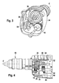
- FIG. 1 shows a section of a hand tool, namely a percussion drill, with a shift gear formed by a sliding gear 32 ( FIGS. 1 to 8 ).
- the sliding gear 32 is arranged in a gear housing 34 of the power tool and has a Doppelstirnrad 36 with two fixedly connected spur gears, which have different diameters and rotatably on a work spindle 38 and are mounted together displaceable in the direction of a Z-axis ( FIGS. 3, 4 and 7 ).
- the work spindle 38 is formed as a splined shaft and is directly connected rotationally fixed with a tool chuck 40 of the power tool.
- By a displacement of the double spur gear 36 in the direction of the Z-axis of the spur gears of the same can be coupled to an intermediate shaft 42 rotatably mounted gears 44, 46 ( FIGS. 3, 4 and 6 ).
- the handheld power tool has a handheld power tool switching unit with a rotary toggle unit 10, which has a rotationally drivable coupling unit 12 designed as an eccentric unit for coupling to a switching element 14 designed as an adjusting slide ( FIGS. 1, 2, 4 and 8 to 21).
- the coupling unit 12 has an output element 28 formed by an eccentric pin, which engages in a slot 70 of the switching element 14 ( FIGS. 4 and 8th ).
- the switching element 14 is formed by a bending plate part and engages with an integrally formed arm 48 between the two spur gears of the Doppelstirnrads 36.
- the hand tool machine switching unit comprises a formed by a leg spring energy storage element 16 which is provided for storing a switching energy in the case of preselection and in the rotary knob unit 10 is integrated.
- the coupling unit 12, the Energy storage element 16 and a handle unit 60 of the rotary knob unit 10 are parts of a common assembly.
- the rotary knob unit 10 is inserted into a recess 50 of the gear housing 34 in a plug-in direction 56 and is secured against the plug-in direction 56 via a latching connection 52 in a holding plate 54 arranged in the gear housing 34 ( Figures 2 . 3 and 5 ).
- the holding plate 54 has a U-shaped receiving area 58 into which the rotary toggle unit 10 is latched.
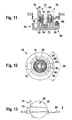
- the energy storage element 16 or the leg spring is arranged in the power flow between a first rotationally drivable shaft 18 of the coupling unit 12 and a second rotationally driven shaft 20 of the handle unit 60 of the rotary knob unit 10, wherein the leg spring to several 360 ° about the rotatably driven shafts 18, 20 extends ( Figures 10 . 11 . 12 . 15 to 21 ).
- the first formed as a hollow shaft shaft 18 of the coupling unit 12 is disposed in the second, also designed as a hollow shaft shaft 20 of the handle unit 60 and is rotatably supported by a molded journal 72 in a bearing bush 74 of the handle unit 60.
- the shafts 18, 20 each have a recess 22, 24 extending in the circumferential direction of the shafts 18, 20 over an angular range 26 of about 110 ° (see, in particular FIG. 12 ).
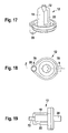
- the shaft 18 is formed integrally with the output element 28 designed as an eccentric pin and with the bearing journal 72 (cf., in particular, 17 to 21).
- the shaft 20 is integrally formed with an output element 30 of the handle unit 60, with a gripping surface forming a handle element (see, in particular FIG. 11 ).
- the leg spring is designed as a helical spring with a plurality of turns and has at one in the direction of a screw axis 62 of the leg spring, which substantially coincides with a rotational axis 64 of the rotary knob unit 10, first end a first radially inwardly projecting leg 66 and at one in the direction of the Schaubachse 62 second end of a second radially inwardly projecting leg 68 ( Figures 2 . 10 . 11, 12 . 15 and 16 ).
- the legs 66, 68 protrude in the radial direction inwardly through the recess 24 of the shaft 20 in the recess 22 of the shaft 18 and are biased to the recesses 22, 24 delimiting edges of the shafts 18, 20 at ( FIG. 12 ).
- the handle unit 60 Is rotated by an operator, the handle unit 60 from a first rotational position 82 or 84 for switching from one gear to another gear in a second rotational position 84 and 82 about the axis of rotation 64 by 180 ° and lies between the gears to be switched no tooth-on Tooth position, the eccentric pin of the coupling unit 12 is rotated in switching positions 76 and 78 and displaced by means of engaging in the slot 70 eccentric pin on a bearing axis 86 slidably mounted switching element 14 and switched to be switched gear ( FIGS. 1, 2 . 14 and 18 ).
- leg 66 or 68 interacts with stops 88, 90 of the handheld power tool switching unit after an angle of rotation of 110 ° of the angular range 26, parts of the leg spring being bridged in the force flow.
- the eccentric pin In the switching positions 76, 78, the eccentric pin is in gear shifts respectively along a pulse axis Z, along which an impulse of an unspecified striking mechanism of the power tool in operation acts on a tool inserted into the power tool insert, in a reversal position, whereby the leg spring along the Pulse axis Z is decoupled from vibrations.
- the leg spring is preloaded in the switch positions.
- the handle unit 60 is secured with an integrated, resiliently mounted locking pin 80 in the rotational positions 82, 84 in the circumferential direction by this is engaged in the switching positions 76, 78 in recesses of the gear housing 34.
Claims (9)
- Unité de commande de machine-outil à main comprenant une unité de bouton tournant (10) qui présente une unité d'accouplement (12) pouvant être entraînée en rotation pour l'accouplement à au moins un élément de commutation (14), et au moins un élément accumulateur d'énergie (16) qui est prévu pour accumuler une énergie de commutation dans le cas d'une présélection et qui est intégré dans l'unité de bouton tournant (10), caractérisée en ce que l'élément accumulateur d'énergie (16) présente au moins un ressort à branches qui s'étend sur au moins 180° autour d'au moins un axe (18, 20) de l'unité de bouton tournant (10) pouvant être entraîné en rotation, et l'unité de couplage (12) présente au moins une unité excentrique (28).
- Unité de commande de machine-outil à main selon la revendication 1, caractérisée en ce que l'élément accumulateur d'énergie (16) est disposé dans le flux de force entre un premier axe (18) de l'unité de bouton tournant (10) pouvant être entraîné en rotation et un deuxième axe (20) de l'unité de bouton tournant (10) pouvant être entraîné en rotation.
- Unité de commande de machine-outil à main selon la revendication 2, caractérisée en ce que le premier axe (18) est disposé au moins en partie dans le deuxième axe (20).
- Unité de commande de machine-outil à main selon la revendication 2 ou 3, caractérisée en ce qu'au moins l'un des axes (18, 20) présente un évidement (22, 24) qui s'étend dans la direction périphérique des axes (18, 20) sur une plage angulaire (26) supérieure à 30°.
- Unité de commande de machine-outil à main selon l'une quelconque des revendications 2 à 4, caractérisée en ce qu'au moins l'un des axes (18, 20) est réalisé d'une seule pièce avec un élément de sortie (28, 30) de l'unité de bouton tournant (10).
- Unité de commande de machine-outil à main selon l'une quelconque des revendications précédentes, caractérisée en ce que l'élément accumulateur d'énergie (16) présente au moins un élément de ressort précontraint dans une position de commutation (76, 78).
- Unité de commande de machine-outil à main selon l'une quelconque des revendications précédentes, caractérisée par au moins une butée mécanique (88, 90) pour l'entraînement de l'unité d'accouplement (12).
- Machine-outil à main comprenant une unité de commande de machine-outil à main selon l'une quelconque des revendications précédentes.
- Machine-outil à main selon la revendication 8, caractérisée par une transmission à pignon baladeur (32).
Applications Claiming Priority (2)
| Application Number | Priority Date | Filing Date | Title |
|---|---|---|---|
| DE102009028622A DE102009028622A1 (de) | 2009-08-18 | 2009-08-18 | Handwerkzeugmaschinenschalteinheit |
| PCT/EP2010/059601 WO2011020644A1 (fr) | 2009-08-18 | 2010-07-06 | Unité de commande pour machine-outil à main |
Publications (2)
| Publication Number | Publication Date |
|---|---|
| EP2467238A1 EP2467238A1 (fr) | 2012-06-27 |
| EP2467238B1 true EP2467238B1 (fr) | 2013-05-01 |
Family
ID=42536346
Family Applications (1)
| Application Number | Title | Priority Date | Filing Date |
|---|---|---|---|
| EP10732339.6A Active EP2467238B1 (fr) | 2009-08-18 | 2010-07-06 | Unité de commande pour machine-outil à main |
Country Status (6)
| Country | Link |
|---|---|
| US (1) | US9643309B2 (fr) |
| EP (1) | EP2467238B1 (fr) |
| CN (1) | CN102481688B (fr) |
| DE (1) | DE102009028622A1 (fr) |
| RU (1) | RU2550462C2 (fr) |
| WO (1) | WO2011020644A1 (fr) |
Families Citing this family (9)
| Publication number | Priority date | Publication date | Assignee | Title |
|---|---|---|---|---|
| CN101758486B (zh) * | 2010-01-21 | 2011-09-28 | 浙江海王电器有限公司 | 轻型单钮多功能电锤 |
| CN201848770U (zh) * | 2010-09-20 | 2011-06-01 | 胡继宁 | 具有安全换挡装置的手持式电动工具 |
| DE102012202278A1 (de) * | 2012-02-15 | 2013-08-22 | Hilti Aktiengesellschaft | Handwerkzeugmaschine |
| CN102837296A (zh) * | 2012-10-02 | 2012-12-26 | 浙江奔宇工具有限公司 | 电锤的拨档装置 |
| US10668614B2 (en) | 2015-06-05 | 2020-06-02 | Ingersoll-Rand Industrial U.S., Inc. | Impact tools with ring gear alignment features |
| US10418879B2 (en) * | 2015-06-05 | 2019-09-17 | Ingersoll-Rand Company | Power tool user interfaces |
| WO2016196918A1 (fr) | 2015-06-05 | 2016-12-08 | Ingersoll-Rand Company | Interfaces utilisateur d'outil électrique |
| US11260517B2 (en) | 2015-06-05 | 2022-03-01 | Ingersoll-Rand Industrial U.S., Inc. | Power tool housings |
| US11491616B2 (en) | 2015-06-05 | 2022-11-08 | Ingersoll-Rand Industrial U.S., Inc. | Power tools with user-selectable operational modes |
Family Cites Families (11)
| Publication number | Priority date | Publication date | Assignee | Title |
|---|---|---|---|---|
| DE4000822A1 (de) * | 1990-01-13 | 1991-07-18 | Bosch Gmbh Robert | Elektrisch betriebene handwerkzeugmaschine |
| BG51906A1 (en) * | 1992-02-11 | 1993-11-15 | Ganchev | Device for commutation the revolutions of a hand electrical two-speed drilling machine |
| WO1996015863A1 (fr) | 1994-11-22 | 1996-05-30 | United Technologies Corporation | Procede de nettoyage d'aubes de turbines aux ultrasons |
| GB9621202D0 (en) * | 1996-10-11 | 1996-11-27 | Black & Decker Inc | Mode change switch |
| RU2174895C2 (ru) | 1999-12-01 | 2001-10-20 | Колган Юрий Никитович | Ручная машина |
| DE10007665A1 (de) * | 2000-02-19 | 2001-09-06 | Scintilla Ag | Werkzeugmaschine |
| DE102004058175B4 (de) | 2004-12-02 | 2019-10-31 | Robert Bosch Gmbh | Handwerkzeugmaschine mit anatomisch verbessertem Schaltelement |
| JP4812471B2 (ja) * | 2006-03-09 | 2011-11-09 | 株式会社マキタ | 作業工具 |
| DE102007009986A1 (de) | 2007-03-02 | 2008-09-04 | Robert Bosch Gmbh | Handwerkzeugmaschine |
| US8251156B2 (en) | 2008-10-30 | 2012-08-28 | Black & Decker Inc. | Compliant shifting mechanism for right angle drill |
| DE102008054786A1 (de) * | 2008-12-17 | 2010-07-01 | Hilti Aktiengesellschaft | Drehschalter |
-
2009
- 2009-08-18 DE DE102009028622A patent/DE102009028622A1/de not_active Withdrawn
-
2010
- 2010-07-06 RU RU2012110120/02A patent/RU2550462C2/ru active
- 2010-07-06 CN CN201080036610.7A patent/CN102481688B/zh active Active
- 2010-07-06 US US13/390,467 patent/US9643309B2/en active Active
- 2010-07-06 EP EP10732339.6A patent/EP2467238B1/fr active Active
- 2010-07-06 WO PCT/EP2010/059601 patent/WO2011020644A1/fr active Application Filing
Also Published As
| Publication number | Publication date |
|---|---|
| CN102481688B (zh) | 2015-01-28 |
| US20120234568A1 (en) | 2012-09-20 |
| DE102009028622A1 (de) | 2011-02-24 |
| RU2012110120A (ru) | 2013-09-27 |
| CN102481688A (zh) | 2012-05-30 |
| EP2467238A1 (fr) | 2012-06-27 |
| US9643309B2 (en) | 2017-05-09 |
| RU2550462C2 (ru) | 2015-05-10 |
| WO2011020644A1 (fr) | 2011-02-24 |
Similar Documents
| Publication | Publication Date | Title |
|---|---|---|
| EP2467238B1 (fr) | Unité de commande pour machine-outil à main | |
| EP2129496B1 (fr) | Machine-outil portative | |
| DE102009054930B4 (de) | Bohrmaschine | |
| DE102011078082B4 (de) | Handwerkzeugmaschine, insbesondere Bohr- oder Schraubgerät | |
| DE202009000793U1 (de) | Angetriebenes Werkzeug | |
| EP0373106B1 (fr) | Outil à main avec boîte d'engrenage | |
| WO2010023027A1 (fr) | Dispositif d’engrenage de machine-outil | |
| EP2342050B1 (fr) | Machine-outil manuelle équipée d'une transmission débrayable | |
| DE10312980A1 (de) | Elektrohandwerkzeugmaschine | |
| WO2012156120A1 (fr) | Logement d'outil | |
| EP1259357B1 (fr) | Machine-outil | |
| DE102012202278A1 (de) | Handwerkzeugmaschine | |
| WO2012084669A1 (fr) | Machine-outil à main | |
| DE102011075858A1 (de) | Werkzeugaufnahme | |
| DE102007010180A1 (de) | Handwerkzeugmaschine | |
| DE102004055236A1 (de) | Handwerkzeugmaschine mit wählbaren Betriebarten | |
| DE102010064369B4 (de) | Handwerkzeugmaschinenspannvorrichtung | |
| DE102010064371B4 (de) | Handwerkzeugmaschinenspannvorrichtung mit Schaltelement | |
| EP2104594B1 (fr) | Machine-outil portative | |
| DE102016224577A1 (de) | Handwerkzeugmaschine | |
| WO2008107231A1 (fr) | Machine-outil portative | |
| EP1127644B1 (fr) | Outil électrique à main | |
| WO2008077660A1 (fr) | Dispositif de commutation pour machine-outil à main | |
| WO2016150659A1 (fr) | Machine-outil portative | |
| DE102010064366A1 (de) | Handwerkzeugmaschinenspannvorrichtung |
Legal Events
| Date | Code | Title | Description |
|---|---|---|---|
| PUAI | Public reference made under article 153(3) epc to a published international application that has entered the european phase |
Free format text: ORIGINAL CODE: 0009012 |
|
| 17P | Request for examination filed |
Effective date: 20120319 |
|
| AK | Designated contracting states |
Kind code of ref document: A1 Designated state(s): AL AT BE BG CH CY CZ DE DK EE ES FI FR GB GR HR HU IE IS IT LI LT LU LV MC MK MT NL NO PL PT RO SE SI SK SM TR |
|
| DAX | Request for extension of the european patent (deleted) | ||
| GRAP | Despatch of communication of intention to grant a patent |
Free format text: ORIGINAL CODE: EPIDOSNIGR1 |
|
| GRAS | Grant fee paid |
Free format text: ORIGINAL CODE: EPIDOSNIGR3 |
|
| GRAA | (expected) grant |
Free format text: ORIGINAL CODE: 0009210 |
|
| AK | Designated contracting states |
Kind code of ref document: B1 Designated state(s): AL AT BE BG CH CY CZ DE DK EE ES FI FR GB GR HR HU IE IS IT LI LT LU LV MC MK MT NL NO PL PT RO SE SI SK SM TR |
|
| REG | Reference to a national code |
Ref country code: GB Ref legal event code: FG4D Free format text: NOT ENGLISH |
|
| REG | Reference to a national code |
Ref country code: CH Ref legal event code: EP Ref country code: AT Ref legal event code: REF Ref document number: 609597 Country of ref document: AT Kind code of ref document: T Effective date: 20130515 |
|
| REG | Reference to a national code |
Ref country code: IE Ref legal event code: FG4D Free format text: LANGUAGE OF EP DOCUMENT: GERMAN |
|
| REG | Reference to a national code |
Ref country code: DE Ref legal event code: R096 Ref document number: 502010003201 Country of ref document: DE Effective date: 20130627 |
|
| REG | Reference to a national code |
Ref country code: NL Ref legal event code: VDEP Effective date: 20130501 |
|
| REG | Reference to a national code |
Ref country code: LT Ref legal event code: MG4D |
|
| PG25 | Lapsed in a contracting state [announced via postgrant information from national office to epo] |
Ref country code: SE Free format text: LAPSE BECAUSE OF FAILURE TO SUBMIT A TRANSLATION OF THE DESCRIPTION OR TO PAY THE FEE WITHIN THE PRESCRIBED TIME-LIMIT Effective date: 20130501 Ref country code: IS Free format text: LAPSE BECAUSE OF FAILURE TO SUBMIT A TRANSLATION OF THE DESCRIPTION OR TO PAY THE FEE WITHIN THE PRESCRIBED TIME-LIMIT Effective date: 20130901 Ref country code: LT Free format text: LAPSE BECAUSE OF FAILURE TO SUBMIT A TRANSLATION OF THE DESCRIPTION OR TO PAY THE FEE WITHIN THE PRESCRIBED TIME-LIMIT Effective date: 20130501 Ref country code: ES Free format text: LAPSE BECAUSE OF FAILURE TO SUBMIT A TRANSLATION OF THE DESCRIPTION OR TO PAY THE FEE WITHIN THE PRESCRIBED TIME-LIMIT Effective date: 20130812 Ref country code: FI Free format text: LAPSE BECAUSE OF FAILURE TO SUBMIT A TRANSLATION OF THE DESCRIPTION OR TO PAY THE FEE WITHIN THE PRESCRIBED TIME-LIMIT Effective date: 20130501 Ref country code: SI Free format text: LAPSE BECAUSE OF FAILURE TO SUBMIT A TRANSLATION OF THE DESCRIPTION OR TO PAY THE FEE WITHIN THE PRESCRIBED TIME-LIMIT Effective date: 20130501 Ref country code: PT Free format text: LAPSE BECAUSE OF FAILURE TO SUBMIT A TRANSLATION OF THE DESCRIPTION OR TO PAY THE FEE WITHIN THE PRESCRIBED TIME-LIMIT Effective date: 20130902 Ref country code: GR Free format text: LAPSE BECAUSE OF FAILURE TO SUBMIT A TRANSLATION OF THE DESCRIPTION OR TO PAY THE FEE WITHIN THE PRESCRIBED TIME-LIMIT Effective date: 20130802 Ref country code: NO Free format text: LAPSE BECAUSE OF FAILURE TO SUBMIT A TRANSLATION OF THE DESCRIPTION OR TO PAY THE FEE WITHIN THE PRESCRIBED TIME-LIMIT Effective date: 20130801 |
|
| PG25 | Lapsed in a contracting state [announced via postgrant information from national office to epo] |
Ref country code: HR Free format text: LAPSE BECAUSE OF FAILURE TO SUBMIT A TRANSLATION OF THE DESCRIPTION OR TO PAY THE FEE WITHIN THE PRESCRIBED TIME-LIMIT Effective date: 20130501 Ref country code: CY Free format text: LAPSE BECAUSE OF FAILURE TO SUBMIT A TRANSLATION OF THE DESCRIPTION OR TO PAY THE FEE WITHIN THE PRESCRIBED TIME-LIMIT Effective date: 20130501 Ref country code: BG Free format text: LAPSE BECAUSE OF FAILURE TO SUBMIT A TRANSLATION OF THE DESCRIPTION OR TO PAY THE FEE WITHIN THE PRESCRIBED TIME-LIMIT Effective date: 20130801 Ref country code: PL Free format text: LAPSE BECAUSE OF FAILURE TO SUBMIT A TRANSLATION OF THE DESCRIPTION OR TO PAY THE FEE WITHIN THE PRESCRIBED TIME-LIMIT Effective date: 20130501 |
|
| PG25 | Lapsed in a contracting state [announced via postgrant information from national office to epo] |
Ref country code: LV Free format text: LAPSE BECAUSE OF FAILURE TO SUBMIT A TRANSLATION OF THE DESCRIPTION OR TO PAY THE FEE WITHIN THE PRESCRIBED TIME-LIMIT Effective date: 20130501 |
|
| BERE | Be: lapsed |
Owner name: ROBERT BOSCH G.M.B.H. Effective date: 20130731 |
|
| PG25 | Lapsed in a contracting state [announced via postgrant information from national office to epo] |
Ref country code: EE Free format text: LAPSE BECAUSE OF FAILURE TO SUBMIT A TRANSLATION OF THE DESCRIPTION OR TO PAY THE FEE WITHIN THE PRESCRIBED TIME-LIMIT Effective date: 20130501 Ref country code: CZ Free format text: LAPSE BECAUSE OF FAILURE TO SUBMIT A TRANSLATION OF THE DESCRIPTION OR TO PAY THE FEE WITHIN THE PRESCRIBED TIME-LIMIT Effective date: 20130501 Ref country code: SK Free format text: LAPSE BECAUSE OF FAILURE TO SUBMIT A TRANSLATION OF THE DESCRIPTION OR TO PAY THE FEE WITHIN THE PRESCRIBED TIME-LIMIT Effective date: 20130501 Ref country code: DK Free format text: LAPSE BECAUSE OF FAILURE TO SUBMIT A TRANSLATION OF THE DESCRIPTION OR TO PAY THE FEE WITHIN THE PRESCRIBED TIME-LIMIT Effective date: 20130501 |
|
| PG25 | Lapsed in a contracting state [announced via postgrant information from national office to epo] |
Ref country code: RO Free format text: LAPSE BECAUSE OF FAILURE TO SUBMIT A TRANSLATION OF THE DESCRIPTION OR TO PAY THE FEE WITHIN THE PRESCRIBED TIME-LIMIT Effective date: 20130501 Ref country code: MC Free format text: LAPSE BECAUSE OF FAILURE TO SUBMIT A TRANSLATION OF THE DESCRIPTION OR TO PAY THE FEE WITHIN THE PRESCRIBED TIME-LIMIT Effective date: 20130501 Ref country code: NL Free format text: LAPSE BECAUSE OF FAILURE TO SUBMIT A TRANSLATION OF THE DESCRIPTION OR TO PAY THE FEE WITHIN THE PRESCRIBED TIME-LIMIT Effective date: 20130501 Ref country code: IT Free format text: LAPSE BECAUSE OF FAILURE TO SUBMIT A TRANSLATION OF THE DESCRIPTION OR TO PAY THE FEE WITHIN THE PRESCRIBED TIME-LIMIT Effective date: 20130501 |
|
| PLBE | No opposition filed within time limit |
Free format text: ORIGINAL CODE: 0009261 |
|
| STAA | Information on the status of an ep patent application or granted ep patent |
Free format text: STATUS: NO OPPOSITION FILED WITHIN TIME LIMIT |
|
| 26N | No opposition filed |
Effective date: 20140204 |
|
| REG | Reference to a national code |
Ref country code: IE Ref legal event code: MM4A |
|
| REG | Reference to a national code |
Ref country code: FR Ref legal event code: ST Effective date: 20140331 |
|
| PG25 | Lapsed in a contracting state [announced via postgrant information from national office to epo] |
Ref country code: BE Free format text: LAPSE BECAUSE OF NON-PAYMENT OF DUE FEES Effective date: 20130731 |
|
| REG | Reference to a national code |
Ref country code: DE Ref legal event code: R097 Ref document number: 502010003201 Country of ref document: DE Effective date: 20140204 |
|
| PG25 | Lapsed in a contracting state [announced via postgrant information from national office to epo] |
Ref country code: FR Free format text: LAPSE BECAUSE OF NON-PAYMENT OF DUE FEES Effective date: 20130731 |
|
| PG25 | Lapsed in a contracting state [announced via postgrant information from national office to epo] |
Ref country code: IE Free format text: LAPSE BECAUSE OF NON-PAYMENT OF DUE FEES Effective date: 20130706 |
|
| PG25 | Lapsed in a contracting state [announced via postgrant information from national office to epo] |
Ref country code: SM Free format text: LAPSE BECAUSE OF FAILURE TO SUBMIT A TRANSLATION OF THE DESCRIPTION OR TO PAY THE FEE WITHIN THE PRESCRIBED TIME-LIMIT Effective date: 20130501 |
|
| PG25 | Lapsed in a contracting state [announced via postgrant information from national office to epo] |
Ref country code: MT Free format text: LAPSE BECAUSE OF FAILURE TO SUBMIT A TRANSLATION OF THE DESCRIPTION OR TO PAY THE FEE WITHIN THE PRESCRIBED TIME-LIMIT Effective date: 20130501 Ref country code: TR Free format text: LAPSE BECAUSE OF FAILURE TO SUBMIT A TRANSLATION OF THE DESCRIPTION OR TO PAY THE FEE WITHIN THE PRESCRIBED TIME-LIMIT Effective date: 20130501 |
|
| PG25 | Lapsed in a contracting state [announced via postgrant information from national office to epo] |
Ref country code: MK Free format text: LAPSE BECAUSE OF FAILURE TO SUBMIT A TRANSLATION OF THE DESCRIPTION OR TO PAY THE FEE WITHIN THE PRESCRIBED TIME-LIMIT Effective date: 20130501 Ref country code: LU Free format text: LAPSE BECAUSE OF NON-PAYMENT OF DUE FEES Effective date: 20130706 Ref country code: HU Free format text: LAPSE BECAUSE OF FAILURE TO SUBMIT A TRANSLATION OF THE DESCRIPTION OR TO PAY THE FEE WITHIN THE PRESCRIBED TIME-LIMIT; INVALID AB INITIO Effective date: 20100706 |
|
| REG | Reference to a national code |
Ref country code: AT Ref legal event code: MM01 Ref document number: 609597 Country of ref document: AT Kind code of ref document: T Effective date: 20150706 |
|
| PG25 | Lapsed in a contracting state [announced via postgrant information from national office to epo] |
Ref country code: AT Free format text: LAPSE BECAUSE OF NON-PAYMENT OF DUE FEES Effective date: 20150706 |
|
| PG25 | Lapsed in a contracting state [announced via postgrant information from national office to epo] |
Ref country code: AL Free format text: LAPSE BECAUSE OF FAILURE TO SUBMIT A TRANSLATION OF THE DESCRIPTION OR TO PAY THE FEE WITHIN THE PRESCRIBED TIME-LIMIT Effective date: 20130501 |
|
| PGFP | Annual fee paid to national office [announced via postgrant information from national office to epo] |
Ref country code: GB Payment date: 20230724 Year of fee payment: 14 Ref country code: CH Payment date: 20230801 Year of fee payment: 14 |
|
| PGFP | Annual fee paid to national office [announced via postgrant information from national office to epo] |
Ref country code: DE Payment date: 20230922 Year of fee payment: 14 |