EP2467017B1 - Vorrichtung zur abgabe von flüchtigen substanzen, insbesondere von duftstoffen und/oder insektiziden - Google Patents
Vorrichtung zur abgabe von flüchtigen substanzen, insbesondere von duftstoffen und/oder insektiziden Download PDFInfo
- Publication number
- EP2467017B1 EP2467017B1 EP09777976.3A EP09777976A EP2467017B1 EP 2467017 B1 EP2467017 B1 EP 2467017B1 EP 09777976 A EP09777976 A EP 09777976A EP 2467017 B1 EP2467017 B1 EP 2467017B1
- Authority
- EP
- European Patent Office
- Prior art keywords
- storage medium
- receiving
- receiving device
- support
- air
- Prior art date
- Legal status (The legal status is an assumption and is not a legal conclusion. Google has not performed a legal analysis and makes no representation as to the accuracy of the status listed.)
- Not-in-force
Links
- 239000000126 substance Substances 0.000 title claims description 38
- 239000003205 fragrance Substances 0.000 title claims description 10
- 239000002917 insecticide Substances 0.000 title claims description 10
- 238000003032 molecular docking Methods 0.000 claims description 68
- 239000012528 membrane Substances 0.000 claims description 29
- 238000003780 insertion Methods 0.000 claims description 19
- 230000037431 insertion Effects 0.000 claims description 19
- 230000001105 regulatory effect Effects 0.000 claims description 9
- 239000007788 liquid Substances 0.000 claims description 5
- 230000009977 dual effect Effects 0.000 claims description 2
- 239000011888 foil Substances 0.000 claims description 2
- 239000003570 air Substances 0.000 description 105
- 239000000463 material Substances 0.000 description 7
- 230000009849 deactivation Effects 0.000 description 6
- 239000012080 ambient air Substances 0.000 description 4
- 238000009792 diffusion process Methods 0.000 description 4
- 230000000694 effects Effects 0.000 description 4
- 238000004146 energy storage Methods 0.000 description 4
- 230000008020 evaporation Effects 0.000 description 4
- 238000001704 evaporation Methods 0.000 description 4
- 238000005286 illumination Methods 0.000 description 3
- 230000004913 activation Effects 0.000 description 2
- 239000004480 active ingredient Substances 0.000 description 2
- 230000008901 benefit Effects 0.000 description 2
- 239000011521 glass Substances 0.000 description 2
- 238000000034 method Methods 0.000 description 2
- 229920003023 plastic Polymers 0.000 description 2
- XAGFODPZIPBFFR-UHFFFAOYSA-N aluminium Chemical compound [Al] XAGFODPZIPBFFR-UHFFFAOYSA-N 0.000 description 1
- 229910052782 aluminium Inorganic materials 0.000 description 1
- 238000010276 construction Methods 0.000 description 1
- 230000001419 dependent effect Effects 0.000 description 1
- 239000003814 drug Substances 0.000 description 1
- 229940079593 drug Drugs 0.000 description 1
- 230000001747 exhibiting effect Effects 0.000 description 1
- 239000002657 fibrous material Substances 0.000 description 1
- 238000010438 heat treatment Methods 0.000 description 1
- 230000004941 influx Effects 0.000 description 1
- 230000001795 light effect Effects 0.000 description 1
- 230000014759 maintenance of location Effects 0.000 description 1
- 230000008569 process Effects 0.000 description 1
- 238000004886 process control Methods 0.000 description 1
- 239000004753 textile Substances 0.000 description 1
- 230000007704 transition Effects 0.000 description 1
- 239000012780 transparent material Substances 0.000 description 1
Images


Classifications
-
- A—HUMAN NECESSITIES
- A01—AGRICULTURE; FORESTRY; ANIMAL HUSBANDRY; HUNTING; TRAPPING; FISHING
- A01M—CATCHING, TRAPPING OR SCARING OF ANIMALS; APPARATUS FOR THE DESTRUCTION OF NOXIOUS ANIMALS OR NOXIOUS PLANTS
- A01M1/00—Stationary means for catching or killing insects
- A01M1/20—Poisoning, narcotising, or burning insects
- A01M1/2022—Poisoning or narcotising insects by vaporising an insecticide
- A01M1/2027—Poisoning or narcotising insects by vaporising an insecticide without heating
- A01M1/2033—Poisoning or narcotising insects by vaporising an insecticide without heating using a fan
-
- A—HUMAN NECESSITIES
- A61—MEDICAL OR VETERINARY SCIENCE; HYGIENE
- A61L—METHODS OR APPARATUS FOR STERILISING MATERIALS OR OBJECTS IN GENERAL; DISINFECTION, STERILISATION OR DEODORISATION OF AIR; CHEMICAL ASPECTS OF BANDAGES, DRESSINGS, ABSORBENT PADS OR SURGICAL ARTICLES; MATERIALS FOR BANDAGES, DRESSINGS, ABSORBENT PADS OR SURGICAL ARTICLES
- A61L9/00—Disinfection, sterilisation or deodorisation of air
- A61L9/015—Disinfection, sterilisation or deodorisation of air using gaseous or vaporous substances, e.g. ozone
- A61L9/04—Disinfection, sterilisation or deodorisation of air using gaseous or vaporous substances, e.g. ozone using substances evaporated in the air without heating
- A61L9/12—Apparatus, e.g. holders, therefor
- A61L9/122—Apparatus, e.g. holders, therefor comprising a fan
-
- Y—GENERAL TAGGING OF NEW TECHNOLOGICAL DEVELOPMENTS; GENERAL TAGGING OF CROSS-SECTIONAL TECHNOLOGIES SPANNING OVER SEVERAL SECTIONS OF THE IPC; TECHNICAL SUBJECTS COVERED BY FORMER USPC CROSS-REFERENCE ART COLLECTIONS [XRACs] AND DIGESTS
- Y10—TECHNICAL SUBJECTS COVERED BY FORMER USPC
- Y10S—TECHNICAL SUBJECTS COVERED BY FORMER USPC CROSS-REFERENCE ART COLLECTIONS [XRACs] AND DIGESTS
- Y10S261/00—Gas and liquid contact apparatus
- Y10S261/88—Aroma dispensers
Definitions
- the invention relates to a device for dispensing volatile substances, in particular fragrances and / or insecticides, according to the preamble of claim 1, see eg document GB-A-2 298 793 ,
- Such devices for delivery of volatile substances are well known, for example in connection with a heater having evaporators, in which a liquid-wick sucked to increase the evaporation rate in a recess or bulge of a heating block of the evaporation device protrudes.
- a device for dispensing volatile substances comprises at least one storage medium containing at least one substance to be dispensed, wherein at least one means for generating at least one air stream is provided which comprises at least one air stream that at least a storage medium is directed to increase the release rate of the substance to be dispensed to the environment from the uninfluenced state.
- the at least one air flow generated by the means for generating at least one air stream flows around and / or against the storage medium in a defined area.
- the release rate or "evaporation rate" of such storage media can be increased, in which at least one liquid and / or at least one gel diffuses from the storage medium into the environment via a type of membrane. Because the flow of such a storage medium by means of a defined air flow, the substance delivery or the diffusion of the substances to be dispensed through the membrane is accelerated, which in turn significantly increases the product efficiency.
- fragrances and / or insecticides are active ingredients that can be evaporated or volatilized into the environment, for example fragrances and / or insecticides.
- the at least one means for generating at least one air stream is preferably formed by a fan and / or blower and / or fan assembly having, for example, at least one impeller and / or a propeller-like impeller.
- a fan and / or blower and / or fan assembly having, for example, at least one impeller and / or a propeller-like impeller.
- all other suitable means for generating at least one air flow can also be used.
- the invention will be described for reasons of clarity, always in conjunction with the term fan assembly as a concrete means for generating at least one air stream, without this being to be understood as a restriction to a fan assembly. Rather, the term fan arrangement is to be understood here in a comprehensive sense.
- the at least one means (9) for generating at least one air stream is part of a docking station with which the at least one storage medium in a defined docking area indirectly via a holding and / or receiving the at least one storage medium, ie a holding device described in more detail below. and or Recording device, by means of which the at least one storage medium is held, and / or directly releasably connectable.
- Such a docking station thus has a function comparable to a charger for, for example, electrical devices, such as telephones or the like, into which or to which the respective storage medium is simply docked. It is preferably provided that, for example in connection with a set, a plurality of different holding and / or receiving devices holding and / or receiving at least one storage medium and subsequently described in greater detail, and / or depending on the desired concrete Application and use requirements can be docked.
- the holding and / or receiving devices may differ in shape and / or pattern of air inlet openings.
- the holding and / or receiving devices can also differ with regard to the number and the manner of the storage media accommodated therein.
- this docking station has a one-part or multi-part housing in which the at least one means (9) for generating at least one air flow is accommodated.
- the at least one means (9) for generating at least one air flow is accommodated.
- contact protection is provided on the one hand and, on the other hand, a defined air flow can be set via, for example, defined air outlet opening geometries.
- the housing has at least one air outlet opening enabling this air outlet.
- this air outlet opening can also function as an air inlet opening, but it is particularly advantageous for good functionality to provide the at least one air inlet opening separately and independently of the at least one air outlet opening at a suitable location on the housing.
- the fan arrangement in particular its impeller and / or impeller, is assigned directly to the at least one air outlet opening, for example in connection with an upper housing side having the at least one air outlet opening directly below it in the housing, while the at least one Air inlet opening preferably spaced it is arranged in the more lateral housing portion, for example on a side wall and / or in the transition region between a side wall and a housing top.
- the at least one air flow generated by the fan arrangement is preferably directed more or less directly onto the at least one air outlet opening, whereby in turn the desired flow conditions can be set in a simple and reliable manner.
- an indirect air supply from the fan arrangement to the at least one air outlet opening would also be conceivable, for example via a flow channel or the like.
- the docking station is designed as a stand-alone unit with a contact surface and / or a connection surface for the at least one storage medium or the optionally retaining and / or receiving component in order to be able to deposit this on a surface.
- the connection surface is preferably formed by an upwardly facing side surface (surface) of the docking station, from which the at least one docked storage medium or the component accommodating the at least one storage medium projects in a defined spatial direction, preferably in the vertical axis direction, tower-like or box-like or block-like.
- the housing of the docking station has at least one air outlet opening on a housing side facing the at least one storage medium, in particular has at least one air outlet slot as air outlet opening.
- the at least one Luftaustassö réelle and / or the at least one storage medium are arranged and / or associated with one another such that the at least one air stream flows and / or flows around the at least one storage medium to a defined extent.
- this is a specific embodiment in which the at least one air stream flows around and / or flows around the storage medium along a defined inflow surface of the storage medium.
- a defined inflow surface can be formed, for example, by the membrane region already described above.
- the at least one storage medium is received in or held on a holding and / or receiving device which can be connected, in particular releasably connected, to the docking station in a docking area, preferably from can be placed on top and / or docked.
- the term holding and / or receiving device is here to be understood in a comprehensive sense and should include any possibility of holding the at least one storage medium and not only the, albeit preferred, recording the at least one storage medium in a receiving space and thus inside the Holding and / or receiving device.
- the novel technical concept of a docking station to fruition for example, in a first step, the at least one storage medium in the holding and / or Recording device is used and then the so-equipped holding and / or receiving device is preferably docked from more or less above at the docking station.
- the insertion of the at least one storage medium is likewise preferably carried out from above, that is to say at an end of the holding and / or receiving device facing away from the docking area, into which the at least one storage medium is preferably inserted from above.
- the at least one storage medium can also be inserted into the holding and / or receiving device only after docking of the holding and / or receiving device to the docking station.
- the releasable connection of the docking station with the holding and / or receiving device by means of at least one mechanical latching and / or support and / or plug connection, in which case a positive and / or frictional connection is preferred.
- at least one docking station-side latching and / or supporting and / or plug-in element is arranged in the docked connected state of the holding and / or receiving device and docking station with at least one retaining and / or receiving device locking device. and / or support and / or plug counter element cooperates so that the holding and / or receiving device is held with a defined holding force in and / or at the docking station or the docking area of the docking station. This can be done, for example, specifically via mutually associated latching projections or latching lugs on the one hand and latching recesses on the other.
- the holding and / or receiving device in at least one defined outer wall region at least one air inlet opening, via which at least one at least one docking station side air outlet opening effluent air flow from the outside of the holding and / or receiving device forth in this and / or optionally flow out can.
- air inlet openings thus preferably form lateral air inlet openings, which is advantageous in particular with such structures of storage medium and holding and / or receiving device in which a membrane region of a storage medium is arranged in the immediate vicinity of the respectively provided holding and / or receiving device-side air inlet openings, that is this is facing.
- the at least one air inlet opening forms a defined opening pattern and / or releases at least 20%, preferably at least 30%, most preferably at least 40% of the associated storage medium surface in order to achieve sufficient and technically meaningful flow conditions.
- a particularly effective enrichment of the air flow with the substances to be dispensed takes place in the event that several, preferably spaced apart air outlet openings, which are formed in particular by Lucasaustassschlitze at the docking arranged in the docking around the holding and / or receiving device around and / or hold each - and / or receiving device side air inlet openings containing holding and / or receiving device wall areas are assigned.
- the assignment takes place in particular in such a way that the air streams emerging from the docking station-side air outlet openings flow in a defined, essentially rectilinear flow path to the air inlet openings.
- the holding and / or receiving device has a block-like or box-like outer contour with air inlet openings located on opposite outer wall sides, wherein, in addition, in the docking area on opposite sides of the holding and / or receiving device, associated with the wall sides having the air inlet openings , at least one docking station-side air outlet opening, which is preferably formed by at least one Beerauslassschlitz is arranged.
- the docking station has a U-shaped outer contour with U-legs, which surround the holding and / or receiving device with the U-legs at least in regions in a form-fitting manner, in particular at the air inlet elements assigned to each other. and air outlet opening facing away, opposite outer wall sides engage around at least partially positively.
- the at least one air inlet opening of the holding and / or receiving device is designed such that the at least one air flow flows around the at least one storage medium from below along a defined path and / or is formed in that it is fluidly connected to at least one holding and / or receiving device-side flow channel, by means of which the at least one air flow is guided to the receiving space.
- This variant of the invention may in principle be provided as an alternative to the previously described lateral air inlet openings of the holding and / or receiving device, which are associated with the exposed, that is not covered, air outlet openings of the docking station.
- this variant of the invention is particularly preferably provided in addition to the at least one holding and / or receiving device side air inlet opening, which is associated with at least one exposed and not from the holding and / or receiving device covered docking station-side air outlet.
- a particularly effective substance enrichment of the flow air can be achieved, for example, in connection with a membrane region of a storage medium is ensured, which flows a high amount of air over or along this membrane area and causes a very high substance release or substance diffusion into the environment becomes.
- At least one outflow opening is provided thereon.
- This can be formed, for example, by at least one access opening of the receiving space, via which the at least one storage medium can be inserted into the receiving space.
- this at least one outflow opening in a dual function but also by the inflow of the at least one air flow into the receiving space enabling, at least one lateral air inlet opening may be formed.
- the membrane region of a storage medium via which the substance to be dispensed or to be evaporated is released from the storage medium and which Membrane area is flowed by the at least one stream of air and / or flows around, can be formed in different ways or by different materials, such as by a diffusion film. Also fiber materials or textile materials can be used.
- a structure of the storage medium according to the invention provides that the storage medium is formed by a container in which the at least one substance to be dispensed or to be volatilized, for example in the form of a liquid and / or a gel, is accommodated, wherein a defined container wall area is designed as a membrane area.
- This membrane region is preferably covered and / or sealed with a removable cover, for example with a release liner or the like.
- This release liner may be formed of, for example, an aluminum material or the like. This cover is removed immediately before the insertion of the storage medium into the device, so that the substance delivery takes place only to the desired extent in the device itself and not before, if the storage medium is not yet in the desired manner in use.
- the at least one storage medium has a platelet-shaped and / or rectangular shape, wherein preferably a membrane region of the storage medium is formed at least in regions by at least one of the two large-area side surfaces.
- a membrane region of the storage medium is formed at least in regions by at least one of the two large-area side surfaces.
- such a platelet-shaped and / or rectangular storage medium is inserted into the holding and / or receiving device via an access opening holding and / or receiving space-side, preferably inserted and / or positioned by means of a type of guide-block arrangement.
- the holding and / or receiving space has at least one insertion slot with spaced opposite guide grooves, in which the platelet-shaped and / or rectangular storage medium with marginal edge opposite edge areas engages and guided in the predetermined storage medium position can be transferred and / or supported there and / or preserved.
- the holding and / or receiving device or its receiving space may be designed such that only a single storage medium can be inserted into it or these.
- a receiving space in which a plurality, in particular two substantially identically formed and / or spaced from each other transversely to the insertion insertion slots are provided.
- identical or different substances can be volatilized, for example two different and harmonizing fragrances or even a fragrance and an insecticide or even two insecticides, to name but a few examples.
- the remaining insertion slots are then not equipped in this case with storage media.
- the storage medium inserted in the insertion slot is supported in the defined insertion position by means of a stop and / or receiving device-side and / or docking station-side stop element.
- a stop and / or receiving device-side and / or docking station-side stop element for example, in the receiving space of the holding and / or receiving device, for example, at the insertion opening opposite slot end, corresponding stop lugs are provided.
- the at least one means for generating at least one air stream preferably formed by a fan arrangement is preferably operated electrically, preferably by means of at least one energy store, for example a battery or a rechargeable battery.
- the power supply but can of course also be done via an electrical power grid. In the latter case then leads away from the device, for example, from the docking a cable that is connectable by means of a power outlet.
- the plug unit can also be attached directly to the device, for example at the docking station, so that in this case can be dispensed with a cable.
- this preferably has a receptacle for the energy storage, which receptacle is preferably closed by means of at least one cover, for example, a flap or a lid.
- This cover can be hinged either pivotable or even completely removable.
- the receiving compartments form a mounting space between them, in which the at least one fan arrangement, optionally together with further components of the device, is received and / or is mounted.
- the further components may be, for example, further electrical components, such as a printed circuit board and / or a chip and / or a lighting device or the like.
- the at least one energy store that this, relative to the operating position of the device, horizontally and / or vertically aligned inside the docking station.
- a substantially horizontal orientation of the energy storage results in a generally flat, more disc-shaped structure of the docking station, then projects from the example, a previously described holding and / or receiving device for the at least one storage medium with parked on a footprint docking essentially upwards , in particular towers like a tower.
- a fork-like, in particular U-shaped receptacle can be formed on the housing of the docking station, which at least partially surrounds and / or supports the at least one storage medium or the optionally accommodating holding and / or receiving device , in particular at least partially positive fit and / or encompasses and / or supports in a system connection.
- the device according to the invention offers only a single operating mode or only a single operating mode, for example such that when the device is activated, a certain amount of air is generated by the at least one fan arrangement and this is transmitted, for example the docking station-side air outlet openings to the receiving device side air intake openings, for example, flows without the air quantity, the air velocity and the inflow and outflow of the air inlet and outlet openings are variable.
- At least one control and / or regulating device by means of which the at least one fan arrangement is controlled as a function of defined operating parameters, in particular for adjusting the speed and / or the quantity of at least one airflow guided to the at least one storage medium ,
- the at least one fan arrangement can be controlled such that, for example, the speed of a fan wheel is reduced or increased in order to carry out a corresponding adjustment of the air quantity or to set it for the currently selected operating mode.
- At least one closure element for example a flap or the like, by means of which the opening cross-section of the at least one air outlet opening is blocked or released to a defined extent as a function of predetermined operating parameters.
- a closure element can be designed, for example, manually adjustable.
- control via a control and / or regulating device as a function of defined operating parameters, such as, for example, the speed and / or the amount of the air flow, wherein such an adjustment preferably takes place by means of corresponding actuators.
- control and / or regulating device has a memory device in which at least one, preferably a plurality of different preprogrammed operating modes and / or operating cycles is or are stored.
- different programs can be run depending on the user request and, for example, different substance delivery quantities can be set, for example, depending on the time of day and / or depending on the season and / or application.
- a process control in which, for example, in a basic mode the at least one fan arrangement is deactivated and the at least one substance to be dispensed from the fan arrangement evaporates from the storage medium or is discharged from it without airflow support.
- Next is at least one provided additional operating mode in which the at least one fan assembly can then be activated for a defined period of time and, accordingly, a substance discharge supporting air flow can be generated.
- additional operating mode in which the at least one fan assembly can then be activated for a defined period of time and, accordingly, a substance discharge supporting air flow can be generated.
- different program guides or process guides may be provided, such as an operating mode in which the at least one fan assembly is permanently activated.
- At least one additional operating mode may be provided, in which the at least one fan arrangement is activated for a defined period of time and then deactivated for a defined period of time.
- the individual activity and deactivation phases repeat periodically or cyclically.
- these be different in terms of the activity and / or deactivation phases and / or the operating mode, in particular the rotational speed, of the at least one fan arrangement.
- a single switch element may be provided by means of which, for example, in a first switch position, the at least one fan assembly is not actuated, while in a second switch position, the fan assembly for a defined period of time, for example for 15 min. is activated and deactivated for a further, subsequent period of time, for example 15 min. again.
- These activity and / or deactivation phases are then repeated under program control until the switch element is returned to a different position.
- still another switch element position may be provided, in which the at least one fan assembly is operated for example for a long time, for example for 30 min., While the deactivating phase is then chosen shorter, for example, at 15 min. can lie.
- the device has at least one, preferably accessible from the outside switching element by means of which or the respective desired operating state and / or operating mode selectable and / or the device, in particular the at least one fan arrangement can be actuated and / or switched on or off.
- a plurality of switches can in principle be provided, for example a first switch to switch the device on or off and a second switch to select, for example, the respective desired operating state and / or operating mode.
- the operating modes do not have an operating mode in which the fan arrangement is switched off, since this operating state has already been reached by switching the device off with the first switch.
- At least one lighting device can be provided, for example at least one light-emitting diode or the like, by means of which the respective operating state and / or operating mode can be displayed and / or the device, in particular the docking station and / or the at least one storage medium and / or at least one that at least one Storage medium receiving component can be illuminated and / or illuminated.
- This is particularly advantageous when the holding and / or receiving device, which receives the at least one storage medium, at least partially formed of a transparent material, for example of a glass and / or plastic material, since then in certain defined areas of the Holding and / or recording device at the same time a specific lighting effect can be generated.
- the at least one lighting device is covered in the docked state of the holding and / or receiving device.
- the device is designed as a set with a plurality of different holding and / or receiving devices that are compatible with the docking station, so that preferably only a single docking station component this set is that can then be individually equipped and configured with different holding and / or recording devices.
- at least one storage medium can be a set component.
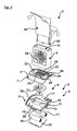
- FIG. 1 different views of a first exemplary embodiment of the invention are shown. That's how it shows Fig. 1a a schematic, perspective front view, the Fig. 1b a front view, the Fig. 1 c a side view and the Fig. 1d a plan view of the device 1 in the assembled state.
- This device 1 has as a base part of a docking station 2, which here as a standalone unit with a footprint 3 and a Pad 4 is designed for a here only receiving device 5 designated holding and / or receiving device.
- the docking station 2 itself is formed by an example of an approximately circular disc geometry exhibiting housing 6, which, as shown in the perspective view of Fig. 1e can be seen, in turn, is formed by an upper housing part 7 and a lower housing part 8.
- the upper housing part 7 and the lower housing part 8 can be detachably connected to one another, for example, by a clip and / or latching connection which is not shown in detail, whereby they can be formed on the housing upper part 7 and on the housing lower part 8 at the edge.
- a clip and / or latching connection which is not shown in detail, whereby they can be formed on the housing upper part 7 and on the housing lower part 8 at the edge.
- an electrically actuated fan assembly 9 is arranged, which has an impeller 10 to produce in a manner to be described in more detail an air flow.
- the fan assembly 9 itself is connected to a control and / or regulating device 11, which in the illustration of Fig.
- FIG. 1b is merely exemplified and schematically represented by a printed circuit board coupled by means of which in dependence on a position of a manual switch 12 (see Fig. 1a, 1b ) in a side wall portion 13 of the housing 6 of the docking station 2, a certain operating mode can be selected.
- a certain operating mode can be selected.
- three different operating modes or operating states can be selected, which are identified by different markings 14a, 14b and 14c (FIG. Fig. 1b are characterized in such a way that when a switch positioning in the region of the mark 14 a, the fan assembly 9 is turned off, for example.
- the fan assembly 9 In a standing on the mark 14b hand switch position then, for example, the fan assembly 9 with a defined speed for a defined time, for example 15 min, be activated. Subsequently, the fan assembly 9 then for a defined time, for example, also 15 min. be disabled. After this deactivation phase, the fan assembly 9 is then reactivated and the cycle begins again.
- the operating mode In the case of a manual switch position in the region of the marking 14c, the operating mode then changes again and, for example, the duration of the activation and / or deactivation phases is changed relative to that or of the switch position 14b, for example such that the respective activation phase lasts longer, for Example 30 min., While the deactivation phase remains the same, for example, in the example case at 15 min .. In principle, it could also be provided in the switch position 14c that the fan arrangement 9 is permanently activated. This could possibly also be realized with an additional switch position, not shown here. The previous remarks are intended merely to illustrate the possibilities of variation by way of
- an additional, separate hand switch 15 may be provided by means of which the device 1 on or off, so that only the respective operating mode is selected with the handset 15.
- 9 batteries 16, 17 are provided for electrical actuation of the fan assembly, which are accessible in over the footprint 3 of the docking station 2 accessible receiving compartments 18, 19 in the lower housing part 8.
- a removable and releasably latchable cover 20 is provided on the footprint 3 of the housing base 8 and thus of the housing 6, which releases the receiving compartments 18, 19 in the removed state of the lid 20.
- Fig. 1j to 1 m It is shown how the lid 20 is removed and the batteries 16, 17 can be removed from the exception compartments 18, 19.
- the receiving compartments 18, 19 are from the top of the housing base 8 and form on opposite sides of the housing base 8 horizontally lying, projection-like elevations, which form between them a mounting space 21, in which in the assembled state, the fan assembly 9, where appropriate, together with the other electronic components of a control and / or regulating device 11 are added.
- the upper housing part 7 has a connection surface 4 for the receiving device 5, which is docked in a docking area 22.
- a docking area 22 In this docking area 22, as shown in particular from Fig. 1e it can be seen, two spaced and approximately opposite latching projections 23, 24 are provided, the latching elements form and, as in particular from Fig. 6a it can be seen, so engage in the receiving device 5, that the Receiving device with a predetermined holding force releasably held on the docking station 2 and / or is supported.
- the number and / or the shape of the respectively provided air inlet and / or air outlet openings is chosen only by way of example.
- other shapes with respect to the slot geometry for example, or a different number of openings or slots are also conceivable at any time.
- one or more air inlet slots 99 are also provided on the housing 6, via which, in particular from the Fig. 1f and Fig. 1e it can be seen, ambient air 100 is sucked into the housing interior.
- the air inlet slots 99 are spaced apart in the present example case formed in the upper corner region of the housing 6, but in principle can also be arranged at other locations, for example in the side wall portion 13 of the upper housing part. 7
- the fan assembly 9 together with the fan wheel 10 is also received and arranged in the housing 6 so that by means of this the air flow 47 is directed directly to the Luftauslassschlitze 25, 26 and 29 respectively.
- the receiving device further comprises a receiving space 31 with two insertion slots 32, 33, in each of which a plate-shaped and rectangular shaped container 34, 35 can be inserted as a storage medium for a substance to be volatilized.
- the two insertion slots 32, 33 are spaced apart transversely to the insertion direction and each have opposite guide grooves 36, 37, in which the plate and rectangular container with edge edge opposite edge plate areas 38, 39 engages and guided in the example in the Fig. 1d in the plan view shown end position is transferable.
- the container has a trough-shaped receptacle 40 for a material to be volatilized, for example a fragrance and / or an insecticide, which may be formed for example by a liquid or a gel.
- a material to be volatilized for example a fragrance and / or an insecticide
- this trough-shaped receptacle on a flat, cuboid outer contour.
- the trough-shaped receptacle 40 is, as in particular from Fig. 5b emerges, covered by a membrane film 41, which in the Fig. 5b is provided with a dot pattern.
- the membrane membrane 41 By means of this membrane membrane 41 forming a membrane region, the liquid or gel absorbed therein in the trough-shaped receptacle 40 can diffuse out into the environment. So that this happens only when the container 34 or 35 is inserted into the receiving device 5, the membrane film 41 is sealed or sealed by means of a cover 42, which, for example, in the Fig. 5b and also in the Fig. 1 e is shown immediately before the insertion of the containers 34, 35 is detected on a projection 43, optionally folded along a bend portion 44 and is then removed from the membrane sheet 41.
- the containers 34, 35 are then inserted into the respectively assigned insertion slots 32, 33 such that the membrane film 41 faces the lateral air inlet slots 27, 28.
- the device 1 is actuated and the fan assembly 9 driven at a defined speed, so ambient air 100 is sucked through the air inlet slots 99 into the housing, then in the housing 6 of the docking station 2, an air flow 47 is generated, which, in particular the Fig. 1f and 1g can be seen, via the exposed Lucasauslassschlitze 25, 26 exits and flows through the side air inlet slots 27, 28 of the receiving device 5 in the receiving space 31 of the receiving device 5.
- this air flow 47 then flows along the surface of the membrane film 41 of the containers 34, 35 upwards, wherein the air stream 47 enriches with the substance diffusing through the membrane film 41.
- This with the to be volatilized or substance to be dispensed enriched air flow then flows, as in the Fig. 1f and 1g is shown only extremely schematically, via an access opening 46 of the receiving space 31 into the environment.
- the delivery rate and / or delivery amount of the substance to the environment is increased by the air flow 47 guided over the membrane foil 41, so that the effectiveness of the device can be substantially increased with regard to, for example, an active ingredient release. Due to the basically given possibility of speed variation and / or the selection of different operating modes or operating cycles, moreover, the speed of the air flow and also the amount of air flow and thus the diffusion speed of the substance through the membrane film 41 could be influenced.
- the internal air outlet slots 29 may optionally be provided.
- a further air flow 54 can flow into this in the receiving space 31 of the receiving device 5 and thus also from below an additional air supply to the respective membrane films 41 of the containers 34, 35 achieved become.
- the receiving device 5 for example, as shown only schematically in the Fig. 6b is shown at the bottom receiving device side air inlet slots 48, 49 on.
- Fig. 6a As this particular in the Fig. 6a is shown schematically and dashed lines, provided in the docking area 22 inside Vietnameseauslassschlitze 29, 30 have a length such that it flows in lying on opposite sides of the receiving device 5 flow channels 51, 52 and from there via at least one internal, lateral flow opening 53 in the Area of the containers 34, 35, in particular in the region of the membrane films 41st can flow in or overflow.
- the receiving device may also be formed as in the Fig. 6c represented, namely with a bottom side, preferably of the same material and integrally formed with the receiving device 5 cover plate 55, which prevents an influx into the receiving space 31.
- the cover plate 55 then simultaneously forms the stop element, which supports the inserted into the insertion slots 31, 32 containers 34, 35 in the desired position.
- Fig. 6a Here's a section along the AA line Fig. 6b represents while the Fig. 6b and 6c different alternative embodiments of the receiving device 5 in the direction of arrow B of Fig. 6a demonstrate.
- Fig. 6b and 6c different alternative embodiments of the receiving device 5 in the direction of arrow B of Fig. 6a demonstrate.
- these can be in the Fig. 6 shown embodiments to all embodiments of recording devices of this invention idea transmitted.
- a light-emitting diode 56 is arranged in the area of the connection surface 4 or in the docking area 22 covered by the reception device 5, which can indicate, for example, the operating state (ON / OFF) of the device 1 or the fan arrangement 9.
- the receiving device is made for example of a transparent plastic and / or glass material, by means of such a light emitting diode 56, of which only one example is shown here, but also alternatively or additionally an advantageous light effect by, for example, illumination of Receiving device 5 or illumination of the receiving space 31 and illumination of the containers 34, 35 can be achieved.
- FIG. 2 an alternative embodiment is shown, which differs from that of Fig. 1 merely insofar as the receiving device 5 has a different pattern of the lateral air inlet slots 27, 28.
- the lower housing part 8 trough- or bowl-shaped, while the upper housing part 7 here plate or is disc-shaped, that is, that the geometry of these two housing parts 7, 8 with respect to that of the embodiment of Fig. 1 is reversed.
- the housing-side air inlet slots 99 are here only in the region of the side wall of the housing lower part 8 extremely exemplary and shown schematically. Otherwise, the structure corresponds to that of the Fig. 1 , so that reference is made in this regard to avoid unnecessary repetition of the above statements, which applies in particular to the functioning of the device.
- the docking station 2 configured with a curved, convex upper housing part 7, which is connectable to a trough-shaped housing lower part 8. Otherwise, here again corresponds to the structure and operation of those or those, as in connection with the Fig. 1 has been described.
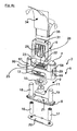
- FIG. 4 Finally, another alternative embodiment is shown, which differs from the embodiment according to the Fig. 1 especially distinguished by another embodiment of the docking station 2.
- the docking station 2 does not have here, as in the previous embodiments of Fig. 1 to 3 horizontally lying batteries or storage compartments, but, based on the in the Fig. 4a and 4b shown operating or mounting position, vertical receiving compartments 18, 19, in which the batteries 16, 17 are taken upright or vertically.
- FIG. 4c it can be seen arranged in the arranged between the two storage compartments 18, 19 for the batteries 16, 17 area a mounting space 21 in which the fan assembly 9 is mounted and received (again, where appropriate, with additional electronic components and components, such as a control and / or regulating device 11).
- the receiving compartments 18, 19 are here part of the lower housing part 8, on which the upper housing part 7 is placed, wherein the upper housing part 7 here has a U-shaped outer contour, with left and right U-legs 57, 58, in which the receiving compartments 18, 19 are included.
- the pad 4 for the receiving device 5 and thus the docking area 22 are recessed and lowered relative to the free U-leg ends, so that in the in the Fig. 4a and in the Fig. 4b shown, mounted or docked state of the receiving device 5, the two U-legs 57, 58 engage around the receiving device 5 on the opposite narrow sides substantially positively and support.
- an additional fixation of the receiving device 5 via the locking projections 23, 24 take place, of which only the locking projection 23 in the Fig. 4c is shown and apparent. Otherwise, the structure and functioning of those of Fig. 1 ,
- the housing-side air inlet slots 99 are also again shown here merely by way of example and in an extremely schematic manner and lie, for example, in the region of the U-legs 57, 58.
Landscapes
- Life Sciences & Earth Sciences (AREA)
- Pest Control & Pesticides (AREA)
- Health & Medical Sciences (AREA)
- General Health & Medical Sciences (AREA)
- Toxicology (AREA)
- Engineering & Computer Science (AREA)
- Insects & Arthropods (AREA)
- Wood Science & Technology (AREA)
- Zoology (AREA)
- Environmental Sciences (AREA)
- Epidemiology (AREA)
- Animal Behavior & Ethology (AREA)
- Public Health (AREA)
- Veterinary Medicine (AREA)
- Catching Or Destruction (AREA)
Applications Claiming Priority (1)
| Application Number | Priority Date | Filing Date | Title |
|---|---|---|---|
| PCT/EP2009/006011 WO2011020480A1 (de) | 2009-08-19 | 2009-08-19 | Vorrichtung zur abgabe von flüchtigen substanzen, insbesondere von duftstoffen und/oder insektiziden |
Publications (2)
| Publication Number | Publication Date |
|---|---|
| EP2467017A1 EP2467017A1 (de) | 2012-06-27 |
| EP2467017B1 true EP2467017B1 (de) | 2013-05-29 |
Family
ID=42181946
Family Applications (1)
| Application Number | Title | Priority Date | Filing Date |
|---|---|---|---|
| EP09777976.3A Not-in-force EP2467017B1 (de) | 2009-08-19 | 2009-08-19 | Vorrichtung zur abgabe von flüchtigen substanzen, insbesondere von duftstoffen und/oder insektiziden |
Country Status (4)
| Country | Link |
|---|---|
| US (1) | US8925905B2 (es) |
| EP (1) | EP2467017B1 (es) |
| ES (1) | ES2425113T3 (es) |
| WO (2) | WO2011020480A1 (es) |
Cited By (4)
| Publication number | Priority date | Publication date | Assignee | Title |
|---|---|---|---|---|
| US10764963B2 (en) | 2016-10-07 | 2020-09-01 | S. C. Johnson & Son, Inc. | Volatile material dispenser |
| CN112483947A (zh) * | 2020-12-17 | 2021-03-12 | 义乌市季隆贸易有限公司 | 一种带有灭蚊功能的室内智能照明灯 |
| US11484022B2 (en) | 2019-10-15 | 2022-11-01 | S. C. Johnson & Son, Inc. | Insect trap device |
| US12290060B2 (en) | 2019-10-15 | 2025-05-06 | S. C. Johnson & Son, Inc. | Insect trap device |
Families Citing this family (14)
| Publication number | Priority date | Publication date | Assignee | Title |
|---|---|---|---|---|
| TW201427582A (zh) * | 2012-12-28 | 2014-07-01 | Hon Hai Prec Ind Co Ltd | 擴充底座散熱裝置 |
| US10112203B2 (en) * | 2013-04-17 | 2018-10-30 | S.C. Johnson & Son, Inc. | Portable volatile material dispenser and method of simulating a flame in same |
| US9327046B2 (en) | 2013-06-13 | 2016-05-03 | The Procter & Gamble Company | Device for evaporating volatile compositions |
| AU2016202404B2 (en) * | 2015-04-29 | 2020-08-06 | Scentsy, Inc. | Diffuser and related methods |
| JP6537898B2 (ja) * | 2015-06-04 | 2019-07-03 | フマキラー株式会社 | 薬剤放散装置 |
| CN105999348B (zh) * | 2016-06-03 | 2018-10-19 | 杭州气味王国科技有限公司 | 一种气味释放装置 |
| USD816201S1 (en) | 2016-09-30 | 2018-04-24 | Kraco Enterprises, Llc. | Air freshener |
| US10265431B2 (en) | 2017-06-08 | 2019-04-23 | Henkel IP & Holding GmbH | Volatile diffuser pods and related systems |
| US10895266B2 (en) * | 2017-09-07 | 2021-01-19 | Regal Beloit America, Inc. | Centrifugal blower assembly and method for assembling the same |
| US11413938B2 (en) | 2019-02-08 | 2022-08-16 | Henkel Ag & Co. Kgaa | Volatile substance distribution system with base unit and removable capsule and airflow coupling therebetween |
| US12564185B2 (en) | 2023-02-03 | 2026-03-03 | SIS Development, Inc. | Automatic optimizing pest control substance delivery system |
| WO2025183833A1 (en) * | 2024-02-26 | 2025-09-04 | Zeya, Inc. | Forced-air scent dispersal device with replaceable scented card |
| USD1112688S1 (en) | 2024-09-13 | 2026-02-10 | Zeya, Inc. | External housing and mounting bracket for forced-air scent dispersal device |
| WO2025220044A1 (en) * | 2024-04-18 | 2025-10-23 | Raghunathan, Vijayalakshmi | Reed sticks assisted displacement device for dispensing precise and micro volume of fragrance oil droplets |
Family Cites Families (7)
| Publication number | Priority date | Publication date | Assignee | Title |
|---|---|---|---|---|
| US2629149A (en) * | 1949-10-22 | 1953-02-24 | David W Yaffe | Deodorizing device |
| GB2298793A (en) * | 1995-03-04 | 1996-09-18 | Westminster Lab Ltd | Vapour dispensers |
| JP2968505B2 (ja) * | 1998-01-14 | 1999-10-25 | 亮一 赤星 | 芳香器 |
| US7132084B1 (en) * | 2001-06-07 | 2006-11-07 | Pende, Inc. | Candle warmer |
| WO2007109504A2 (en) * | 2006-03-16 | 2007-09-27 | Momentum Industries, Llc | Device for distributing volatile fluids in air |
| ES2340644B1 (es) * | 2007-08-07 | 2011-05-26 | Zobele España, S.A. | Dispositivo evaporador de sustancias volatiles sensible al movimiento. |
| US8746505B2 (en) * | 2007-10-29 | 2014-06-10 | S.C. Johnson & Son, Inc. | Multi-sensory product combining reeds, volatile actives diffusion, form-within-a-form construction, and light show capabilities |
-
2009
- 2009-08-19 WO PCT/EP2009/006011 patent/WO2011020480A1/de not_active Ceased
- 2009-08-19 EP EP09777976.3A patent/EP2467017B1/de not_active Not-in-force
- 2009-08-19 US US13/390,794 patent/US8925905B2/en active Active
- 2009-08-19 ES ES09777976T patent/ES2425113T3/es active Active
-
2010
- 2010-01-22 WO PCT/EP2010/000389 patent/WO2011020519A1/de not_active Ceased
Cited By (6)
| Publication number | Priority date | Publication date | Assignee | Title |
|---|---|---|---|---|
| US10764963B2 (en) | 2016-10-07 | 2020-09-01 | S. C. Johnson & Son, Inc. | Volatile material dispenser |
| US11484022B2 (en) | 2019-10-15 | 2022-11-01 | S. C. Johnson & Son, Inc. | Insect trap device |
| US12102078B2 (en) | 2019-10-15 | 2024-10-01 | S. C. Johnson & Son, Inc. | Insect trap device |
| US12290060B2 (en) | 2019-10-15 | 2025-05-06 | S. C. Johnson & Son, Inc. | Insect trap device |
| CN112483947A (zh) * | 2020-12-17 | 2021-03-12 | 义乌市季隆贸易有限公司 | 一种带有灭蚊功能的室内智能照明灯 |
| CN112483947B (zh) * | 2020-12-17 | 2021-11-30 | 江苏日月照明电器有限公司 | 一种带有灭蚊功能的室内智能照明灯 |
Also Published As
| Publication number | Publication date |
|---|---|
| US8925905B2 (en) | 2015-01-06 |
| WO2011020480A1 (de) | 2011-02-24 |
| EP2467017A1 (de) | 2012-06-27 |
| WO2011020519A1 (de) | 2011-02-24 |
| US20120298774A1 (en) | 2012-11-29 |
| ES2425113T3 (es) | 2013-10-11 |
Similar Documents
| Publication | Publication Date | Title |
|---|---|---|
| EP2467017B1 (de) | Vorrichtung zur abgabe von flüchtigen substanzen, insbesondere von duftstoffen und/oder insektiziden | |
| EP0814656B1 (de) | Verdampfervorrichtung | |
| DE3785842T2 (de) | Selbstaendige luftverbesserungsvorrichtung und patrone dafuer. | |
| DE60003134T2 (de) | Gerät zur kontrollierbaren Übertragung einer Flüssigkeit und Anordnung zur Abgabe von übertragenen Flüssigkeiten | |
| US4214146A (en) | Electrically heated vaporizer device for dispensing a thermally volatilizable substance | |
| DE69004733T2 (de) | Luftauffrischer. | |
| DE60317072T2 (de) | Verdampfer | |
| DE69904439T2 (de) | Verdunster für flüchtige substanzen ohne remanenz | |
| DE69606025T2 (de) | Chemischer apparat | |
| EP1108358B1 (de) | Vorrichtung zum Verdampfen von flüchtigen Substanzen, insbesondere von Insektiziden und/oder Duftstoffen | |
| DE2733253C2 (de) | Vorrichtung zum Freisetzen eines verdunstungsfähigen Wirkstoffes | |
| AU741564B2 (en) | Volatile carrier for use with a heating device | |
| EP0722742A2 (de) | Behälter zur Aufnahme von Wirkstoffen wie Duftstoffen, Insektiziden oder dergleichen | |
| EP2431134A2 (de) | Handgeführtes Arbeitsgerät mit einem elektrischen Antriebsmotor | |
| DE3872165T2 (de) | Verdampfer. | |
| EP0197971B1 (de) | Verdampfervorrichtung für in feste trägermaterialien eingelagerte wirkstoffe, wie pyrethrum | |
| EP1468223A1 (de) | Luftbefeuchter | |
| WO2017215728A1 (de) | Vorrichtung zur abgabe, insbesondere zum verdampfen von flüchtigen substanzen, insbesondere von duft- und/oder wirkstoffen | |
| WO2008040304A1 (de) | Vorrichtung zur applikation eines aerosols | |
| DE60212893T2 (de) | Spender von Luftschwebestoffen | |
| DE8502409U1 (de) | Vorrichtung zum Verdampfen von in Zellstoff oder anderen Trägermaterialien eingelagerten Wirkstoffen, wie zum Beispiel Pyrethrum | |
| EP2873427B1 (de) | Raumbeduftungsgerät | |
| DE29815783U1 (de) | Raumbeduftungssystem | |
| EP3620182B1 (de) | Dunstabzugshaube mit beduftungseinheit umfassend einen duftstoffquellenhalter | |
| WO2009071666A1 (de) | Vorrichtung zur raumbeduftung |
Legal Events
| Date | Code | Title | Description |
|---|---|---|---|
| PUAI | Public reference made under article 153(3) epc to a published international application that has entered the european phase |
Free format text: ORIGINAL CODE: 0009012 |
|
| 17P | Request for examination filed |
Effective date: 20120309 |
|
| AK | Designated contracting states |
Kind code of ref document: A1 Designated state(s): AT BE BG CH CY CZ DE DK EE ES FI FR GB GR HR HU IE IS IT LI LT LU LV MC MK MT NL NO PL PT RO SE SI SK SM TR |
|
| DAX | Request for extension of the european patent (deleted) | ||
| GRAP | Despatch of communication of intention to grant a patent |
Free format text: ORIGINAL CODE: EPIDOSNIGR1 |
|
| GRAS | Grant fee paid |
Free format text: ORIGINAL CODE: EPIDOSNIGR3 |
|
| GRAA | (expected) grant |
Free format text: ORIGINAL CODE: 0009210 |
|
| AK | Designated contracting states |
Kind code of ref document: B1 Designated state(s): AT BE BG CH CY CZ DE DK EE ES FI FR GB GR HR HU IE IS IT LI LT LU LV MC MK MT NL NO PL PT RO SE SI SK SM TR |
|
| REG | Reference to a national code |
Ref country code: GB Ref legal event code: FG4D Free format text: NOT ENGLISH |
|
| REG | Reference to a national code |
Ref country code: CH Ref legal event code: EP |
|
| REG | Reference to a national code |
Ref country code: AT Ref legal event code: REF Ref document number: 613787 Country of ref document: AT Kind code of ref document: T Effective date: 20130615 |
|
| REG | Reference to a national code |
Ref country code: IE Ref legal event code: FG4D Free format text: LANGUAGE OF EP DOCUMENT: GERMAN |
|
| REG | Reference to a national code |
Ref country code: DE Ref legal event code: R096 Ref document number: 502009007241 Country of ref document: DE Effective date: 20130725 |
|
| REG | Reference to a national code |
Ref country code: NL Ref legal event code: T3 |
|
| REG | Reference to a national code |
Ref country code: ES Ref legal event code: FG2A Ref document number: 2425113 Country of ref document: ES Kind code of ref document: T3 Effective date: 20131011 |
|
| REG | Reference to a national code |
Ref country code: LT Ref legal event code: MG4D |
|
| PG25 | Lapsed in a contracting state [announced via postgrant information from national office to epo] |
Ref country code: SI Free format text: LAPSE BECAUSE OF FAILURE TO SUBMIT A TRANSLATION OF THE DESCRIPTION OR TO PAY THE FEE WITHIN THE PRESCRIBED TIME-LIMIT Effective date: 20130529 Ref country code: LT Free format text: LAPSE BECAUSE OF FAILURE TO SUBMIT A TRANSLATION OF THE DESCRIPTION OR TO PAY THE FEE WITHIN THE PRESCRIBED TIME-LIMIT Effective date: 20130529 Ref country code: NO Free format text: LAPSE BECAUSE OF FAILURE TO SUBMIT A TRANSLATION OF THE DESCRIPTION OR TO PAY THE FEE WITHIN THE PRESCRIBED TIME-LIMIT Effective date: 20130829 Ref country code: FI Free format text: LAPSE BECAUSE OF FAILURE TO SUBMIT A TRANSLATION OF THE DESCRIPTION OR TO PAY THE FEE WITHIN THE PRESCRIBED TIME-LIMIT Effective date: 20130529 Ref country code: SE Free format text: LAPSE BECAUSE OF FAILURE TO SUBMIT A TRANSLATION OF THE DESCRIPTION OR TO PAY THE FEE WITHIN THE PRESCRIBED TIME-LIMIT Effective date: 20130529 Ref country code: GR Free format text: LAPSE BECAUSE OF FAILURE TO SUBMIT A TRANSLATION OF THE DESCRIPTION OR TO PAY THE FEE WITHIN THE PRESCRIBED TIME-LIMIT Effective date: 20130830 Ref country code: IS Free format text: LAPSE BECAUSE OF FAILURE TO SUBMIT A TRANSLATION OF THE DESCRIPTION OR TO PAY THE FEE WITHIN THE PRESCRIBED TIME-LIMIT Effective date: 20130929 Ref country code: PT Free format text: LAPSE BECAUSE OF FAILURE TO SUBMIT A TRANSLATION OF THE DESCRIPTION OR TO PAY THE FEE WITHIN THE PRESCRIBED TIME-LIMIT Effective date: 20130930 |
|
| PG25 | Lapsed in a contracting state [announced via postgrant information from national office to epo] |
Ref country code: HR Free format text: LAPSE BECAUSE OF FAILURE TO SUBMIT A TRANSLATION OF THE DESCRIPTION OR TO PAY THE FEE WITHIN THE PRESCRIBED TIME-LIMIT Effective date: 20130529 Ref country code: BG Free format text: LAPSE BECAUSE OF FAILURE TO SUBMIT A TRANSLATION OF THE DESCRIPTION OR TO PAY THE FEE WITHIN THE PRESCRIBED TIME-LIMIT Effective date: 20130829 Ref country code: PL Free format text: LAPSE BECAUSE OF FAILURE TO SUBMIT A TRANSLATION OF THE DESCRIPTION OR TO PAY THE FEE WITHIN THE PRESCRIBED TIME-LIMIT Effective date: 20130529 |
|
| PG25 | Lapsed in a contracting state [announced via postgrant information from national office to epo] |
Ref country code: LV Free format text: LAPSE BECAUSE OF FAILURE TO SUBMIT A TRANSLATION OF THE DESCRIPTION OR TO PAY THE FEE WITHIN THE PRESCRIBED TIME-LIMIT Effective date: 20130529 |
|
| PG25 | Lapsed in a contracting state [announced via postgrant information from national office to epo] |
Ref country code: CZ Free format text: LAPSE BECAUSE OF FAILURE TO SUBMIT A TRANSLATION OF THE DESCRIPTION OR TO PAY THE FEE WITHIN THE PRESCRIBED TIME-LIMIT Effective date: 20130529 Ref country code: DK Free format text: LAPSE BECAUSE OF FAILURE TO SUBMIT A TRANSLATION OF THE DESCRIPTION OR TO PAY THE FEE WITHIN THE PRESCRIBED TIME-LIMIT Effective date: 20130529 Ref country code: SK Free format text: LAPSE BECAUSE OF FAILURE TO SUBMIT A TRANSLATION OF THE DESCRIPTION OR TO PAY THE FEE WITHIN THE PRESCRIBED TIME-LIMIT Effective date: 20130529 Ref country code: EE Free format text: LAPSE BECAUSE OF FAILURE TO SUBMIT A TRANSLATION OF THE DESCRIPTION OR TO PAY THE FEE WITHIN THE PRESCRIBED TIME-LIMIT Effective date: 20130529 |
|
| BERE | Be: lapsed |
Owner name: CTR, LDA Effective date: 20130831 |
|
| PG25 | Lapsed in a contracting state [announced via postgrant information from national office to epo] |
Ref country code: RO Free format text: LAPSE BECAUSE OF FAILURE TO SUBMIT A TRANSLATION OF THE DESCRIPTION OR TO PAY THE FEE WITHIN THE PRESCRIBED TIME-LIMIT Effective date: 20130529 |
|
| REG | Reference to a national code |
Ref country code: CH Ref legal event code: PL |
|
| PLBE | No opposition filed within time limit |
Free format text: ORIGINAL CODE: 0009261 |
|
| STAA | Information on the status of an ep patent application or granted ep patent |
Free format text: STATUS: NO OPPOSITION FILED WITHIN TIME LIMIT |
|
| PG25 | Lapsed in a contracting state [announced via postgrant information from national office to epo] |
Ref country code: CH Free format text: LAPSE BECAUSE OF NON-PAYMENT OF DUE FEES Effective date: 20130831 Ref country code: MC Free format text: LAPSE BECAUSE OF FAILURE TO SUBMIT A TRANSLATION OF THE DESCRIPTION OR TO PAY THE FEE WITHIN THE PRESCRIBED TIME-LIMIT Effective date: 20130529 Ref country code: LI Free format text: LAPSE BECAUSE OF NON-PAYMENT OF DUE FEES Effective date: 20130831 |
|
| 26N | No opposition filed |
Effective date: 20140303 |
|
| REG | Reference to a national code |
Ref country code: IE Ref legal event code: MM4A |
|
| PG25 | Lapsed in a contracting state [announced via postgrant information from national office to epo] |
Ref country code: BE Free format text: LAPSE BECAUSE OF NON-PAYMENT OF DUE FEES Effective date: 20130831 |
|
| REG | Reference to a national code |
Ref country code: DE Ref legal event code: R097 Ref document number: 502009007241 Country of ref document: DE Effective date: 20140303 |
|
| PG25 | Lapsed in a contracting state [announced via postgrant information from national office to epo] |
Ref country code: IE Free format text: LAPSE BECAUSE OF NON-PAYMENT OF DUE FEES Effective date: 20130819 |
|
| PG25 | Lapsed in a contracting state [announced via postgrant information from national office to epo] |
Ref country code: SM Free format text: LAPSE BECAUSE OF FAILURE TO SUBMIT A TRANSLATION OF THE DESCRIPTION OR TO PAY THE FEE WITHIN THE PRESCRIBED TIME-LIMIT Effective date: 20130529 |
|
| PG25 | Lapsed in a contracting state [announced via postgrant information from national office to epo] |
Ref country code: CY Free format text: LAPSE BECAUSE OF FAILURE TO SUBMIT A TRANSLATION OF THE DESCRIPTION OR TO PAY THE FEE WITHIN THE PRESCRIBED TIME-LIMIT Effective date: 20130529 Ref country code: TR Free format text: LAPSE BECAUSE OF FAILURE TO SUBMIT A TRANSLATION OF THE DESCRIPTION OR TO PAY THE FEE WITHIN THE PRESCRIBED TIME-LIMIT Effective date: 20130529 Ref country code: MT Free format text: LAPSE BECAUSE OF FAILURE TO SUBMIT A TRANSLATION OF THE DESCRIPTION OR TO PAY THE FEE WITHIN THE PRESCRIBED TIME-LIMIT Effective date: 20130529 |
|
| PG25 | Lapsed in a contracting state [announced via postgrant information from national office to epo] |
Ref country code: LU Free format text: LAPSE BECAUSE OF NON-PAYMENT OF DUE FEES Effective date: 20130819 Ref country code: HU Free format text: LAPSE BECAUSE OF FAILURE TO SUBMIT A TRANSLATION OF THE DESCRIPTION OR TO PAY THE FEE WITHIN THE PRESCRIBED TIME-LIMIT; INVALID AB INITIO Effective date: 20090819 Ref country code: MK Free format text: LAPSE BECAUSE OF FAILURE TO SUBMIT A TRANSLATION OF THE DESCRIPTION OR TO PAY THE FEE WITHIN THE PRESCRIBED TIME-LIMIT Effective date: 20130529 |
|
| REG | Reference to a national code |
Ref country code: AT Ref legal event code: MM01 Ref document number: 613787 Country of ref document: AT Kind code of ref document: T Effective date: 20140819 |
|
| PG25 | Lapsed in a contracting state [announced via postgrant information from national office to epo] |
Ref country code: AT Free format text: LAPSE BECAUSE OF NON-PAYMENT OF DUE FEES Effective date: 20140819 |
|
| REG | Reference to a national code |
Ref country code: FR Ref legal event code: PLFP Year of fee payment: 8 |
|
| PGFP | Annual fee paid to national office [announced via postgrant information from national office to epo] |
Ref country code: NL Payment date: 20160826 Year of fee payment: 8 |
|
| PGFP | Annual fee paid to national office [announced via postgrant information from national office to epo] |
Ref country code: IT Payment date: 20160824 Year of fee payment: 8 Ref country code: GB Payment date: 20160817 Year of fee payment: 8 |
|
| PGFP | Annual fee paid to national office [announced via postgrant information from national office to epo] |
Ref country code: FR Payment date: 20160831 Year of fee payment: 8 |
|
| PGFP | Annual fee paid to national office [announced via postgrant information from national office to epo] |
Ref country code: ES Payment date: 20160808 Year of fee payment: 8 |
|
| PGFP | Annual fee paid to national office [announced via postgrant information from national office to epo] |
Ref country code: DE Payment date: 20161027 Year of fee payment: 8 |
|
| REG | Reference to a national code |
Ref country code: DE Ref legal event code: R119 Ref document number: 502009007241 Country of ref document: DE |
|
| REG | Reference to a national code |
Ref country code: NL Ref legal event code: MM Effective date: 20170901 |
|
| GBPC | Gb: european patent ceased through non-payment of renewal fee |
Effective date: 20170819 |
|
| REG | Reference to a national code |
Ref country code: FR Ref legal event code: ST Effective date: 20180430 |
|
| PG25 | Lapsed in a contracting state [announced via postgrant information from national office to epo] |
Ref country code: NL Free format text: LAPSE BECAUSE OF NON-PAYMENT OF DUE FEES Effective date: 20170901 |
|
| PG25 | Lapsed in a contracting state [announced via postgrant information from national office to epo] |
Ref country code: GB Free format text: LAPSE BECAUSE OF NON-PAYMENT OF DUE FEES Effective date: 20170819 Ref country code: DE Free format text: LAPSE BECAUSE OF NON-PAYMENT OF DUE FEES Effective date: 20180301 |
|
| PG25 | Lapsed in a contracting state [announced via postgrant information from national office to epo] |
Ref country code: IT Free format text: LAPSE BECAUSE OF NON-PAYMENT OF DUE FEES Effective date: 20170819 Ref country code: FR Free format text: LAPSE BECAUSE OF NON-PAYMENT OF DUE FEES Effective date: 20170831 |
|
| REG | Reference to a national code |
Ref country code: ES Ref legal event code: FD2A Effective date: 20181029 |
|
| PG25 | Lapsed in a contracting state [announced via postgrant information from national office to epo] |
Ref country code: ES Free format text: LAPSE BECAUSE OF NON-PAYMENT OF DUE FEES Effective date: 20170820 |