EP2464448B1 - 3d-mikrostrukturierung zur herstellung von mischstrukturen und kanalstrukturen in einer mehrschichttechnologie zur verwendung für reaktoren oder für den bau von reaktoren - Google Patents
3d-mikrostrukturierung zur herstellung von mischstrukturen und kanalstrukturen in einer mehrschichttechnologie zur verwendung für reaktoren oder für den bau von reaktoren Download PDFInfo
- Publication number
- EP2464448B1 EP2464448B1 EP20100744519 EP10744519A EP2464448B1 EP 2464448 B1 EP2464448 B1 EP 2464448B1 EP 20100744519 EP20100744519 EP 20100744519 EP 10744519 A EP10744519 A EP 10744519A EP 2464448 B1 EP2464448 B1 EP 2464448B1
- Authority
- EP
- European Patent Office
- Prior art keywords
- layer
- openings
- individual layers
- another
- channel structure
- Prior art date
- Legal status (The legal status is an assumption and is not a legal conclusion. Google has not performed a legal analysis and makes no representation as to the accuracy of the status listed.)
- Ceased
Links
Images





Classifications
-
- B—PERFORMING OPERATIONS; TRANSPORTING
- B01—PHYSICAL OR CHEMICAL PROCESSES OR APPARATUS IN GENERAL
- B01J—CHEMICAL OR PHYSICAL PROCESSES, e.g. CATALYSIS OR COLLOID CHEMISTRY; THEIR RELEVANT APPARATUS
- B01J19/00—Chemical, physical or physico-chemical processes in general; Their relevant apparatus
- B01J19/0093—Microreactors, e.g. miniaturised or microfabricated reactors
-
- B—PERFORMING OPERATIONS; TRANSPORTING
- B01—PHYSICAL OR CHEMICAL PROCESSES OR APPARATUS IN GENERAL
- B01F—MIXING, e.g. DISSOLVING, EMULSIFYING OR DISPERSING
- B01F33/00—Other mixers; Mixing plants; Combinations of mixers
- B01F33/30—Micromixers
-
- B—PERFORMING OPERATIONS; TRANSPORTING
- B01—PHYSICAL OR CHEMICAL PROCESSES OR APPARATUS IN GENERAL
- B01F—MIXING, e.g. DISSOLVING, EMULSIFYING OR DISPERSING
- B01F25/00—Flow mixers; Mixers for falling materials, e.g. solid particles
- B01F25/40—Static mixers
- B01F25/42—Static mixers in which the mixing is affected by moving the components jointly in changing directions, e.g. in tubes provided with baffles or obstructions
- B01F25/421—Static mixers in which the mixing is affected by moving the components jointly in changing directions, e.g. in tubes provided with baffles or obstructions by moving the components in a convoluted or labyrinthine path
- B01F25/422—Static mixers in which the mixing is affected by moving the components jointly in changing directions, e.g. in tubes provided with baffles or obstructions by moving the components in a convoluted or labyrinthine path between stacked plates, e.g. grooved or perforated plates
-
- B—PERFORMING OPERATIONS; TRANSPORTING
- B01—PHYSICAL OR CHEMICAL PROCESSES OR APPARATUS IN GENERAL
- B01F—MIXING, e.g. DISSOLVING, EMULSIFYING OR DISPERSING
- B01F25/00—Flow mixers; Mixers for falling materials, e.g. solid particles
- B01F25/40—Static mixers
- B01F25/42—Static mixers in which the mixing is affected by moving the components jointly in changing directions, e.g. in tubes provided with baffles or obstructions
- B01F25/43—Mixing tubes, e.g. wherein the material is moved in a radial or partly reversed direction
- B01F25/432—Mixing tubes, e.g. wherein the material is moved in a radial or partly reversed direction with means for dividing the material flow into separate sub-flows and for repositioning and recombining these sub-flows; Cross-mixing, e.g. conducting the outer layer of the material nearer to the axis of the tube or vice-versa
- B01F25/4322—Mixing tubes, e.g. wherein the material is moved in a radial or partly reversed direction with means for dividing the material flow into separate sub-flows and for repositioning and recombining these sub-flows; Cross-mixing, e.g. conducting the outer layer of the material nearer to the axis of the tube or vice-versa essentially composed of stacks of sheets, e.g. corrugated sheets
-
- B—PERFORMING OPERATIONS; TRANSPORTING
- B81—MICROSTRUCTURAL TECHNOLOGY
- B81C—PROCESSES OR APPARATUS SPECIALLY ADAPTED FOR THE MANUFACTURE OR TREATMENT OF MICROSTRUCTURAL DEVICES OR SYSTEMS
- B81C1/00—Manufacture or treatment of devices or systems in or on a substrate
- B81C1/00015—Manufacture or treatment of devices or systems in or on a substrate for manufacturing microsystems
- B81C1/00023—Manufacture or treatment of devices or systems in or on a substrate for manufacturing microsystems without movable or flexible elements
- B81C1/00119—Arrangement of basic structures like cavities or channels, e.g. suitable for microfluidic systems
-
- C—CHEMISTRY; METALLURGY
- C12—BIOCHEMISTRY; BEER; SPIRITS; WINE; VINEGAR; MICROBIOLOGY; ENZYMOLOGY; MUTATION OR GENETIC ENGINEERING
- C12M—APPARATUS FOR ENZYMOLOGY OR MICROBIOLOGY; APPARATUS FOR CULTURING MICROORGANISMS FOR PRODUCING BIOMASS, FOR GROWING CELLS OR FOR OBTAINING FERMENTATION OR METABOLIC PRODUCTS, i.e. BIOREACTORS OR FERMENTERS
- C12M41/00—Means for regulation, monitoring, measurement or control, e.g. flow regulation
- C12M41/12—Means for regulation, monitoring, measurement or control, e.g. flow regulation of temperature
- C12M41/18—Heat exchange systems, e.g. heat jackets or outer envelopes
-
- F—MECHANICAL ENGINEERING; LIGHTING; HEATING; WEAPONS; BLASTING
- F28—HEAT EXCHANGE IN GENERAL
- F28D—HEAT-EXCHANGE APPARATUS, NOT PROVIDED FOR IN ANOTHER SUBCLASS, IN WHICH THE HEAT-EXCHANGE MEDIA DO NOT COME INTO DIRECT CONTACT
- F28D9/00—Heat-exchange apparatus having stationary plate-like or laminated conduit assemblies for both heat-exchange media, the media being in contact with different sides of a conduit wall
- F28D9/0031—Heat-exchange apparatus having stationary plate-like or laminated conduit assemblies for both heat-exchange media, the media being in contact with different sides of a conduit wall the conduits for one heat-exchange medium being formed by paired plates touching each other
- F28D9/0043—Heat-exchange apparatus having stationary plate-like or laminated conduit assemblies for both heat-exchange media, the media being in contact with different sides of a conduit wall the conduits for one heat-exchange medium being formed by paired plates touching each other the plates having openings therein for circulation of at least one heat-exchange medium from one conduit to another
-
- F—MECHANICAL ENGINEERING; LIGHTING; HEATING; WEAPONS; BLASTING
- F28—HEAT EXCHANGE IN GENERAL
- F28F—DETAILS OF HEAT-EXCHANGE AND HEAT-TRANSFER APPARATUS, OF GENERAL APPLICATION
- F28F3/00—Plate-like or laminated elements; Assemblies of plate-like or laminated elements
- F28F3/08—Elements constructed for building-up into stacks, e.g. capable of being taken apart for cleaning
- F28F3/086—Elements constructed for building-up into stacks, e.g. capable of being taken apart for cleaning having one or more openings therein forming tubular heat-exchange passages
-
- B—PERFORMING OPERATIONS; TRANSPORTING
- B01—PHYSICAL OR CHEMICAL PROCESSES OR APPARATUS IN GENERAL
- B01J—CHEMICAL OR PHYSICAL PROCESSES, e.g. CATALYSIS OR COLLOID CHEMISTRY; THEIR RELEVANT APPARATUS
- B01J2219/00—Chemical, physical or physico-chemical processes in general; Their relevant apparatus
- B01J2219/00781—Aspects relating to microreactors
- B01J2219/00783—Laminate assemblies, i.e. the reactor comprising a stack of plates
-
- B—PERFORMING OPERATIONS; TRANSPORTING
- B01—PHYSICAL OR CHEMICAL PROCESSES OR APPARATUS IN GENERAL
- B01J—CHEMICAL OR PHYSICAL PROCESSES, e.g. CATALYSIS OR COLLOID CHEMISTRY; THEIR RELEVANT APPARATUS
- B01J2219/00—Chemical, physical or physico-chemical processes in general; Their relevant apparatus
- B01J2219/00781—Aspects relating to microreactors
- B01J2219/00819—Materials of construction
- B01J2219/00835—Comprising catalytically active material
-
- B—PERFORMING OPERATIONS; TRANSPORTING
- B01—PHYSICAL OR CHEMICAL PROCESSES OR APPARATUS IN GENERAL
- B01J—CHEMICAL OR PHYSICAL PROCESSES, e.g. CATALYSIS OR COLLOID CHEMISTRY; THEIR RELEVANT APPARATUS
- B01J2219/00—Chemical, physical or physico-chemical processes in general; Their relevant apparatus
- B01J2219/00781—Aspects relating to microreactors
- B01J2219/00889—Mixing
-
- B—PERFORMING OPERATIONS; TRANSPORTING
- B81—MICROSTRUCTURAL TECHNOLOGY
- B81B—MICROSTRUCTURAL DEVICES OR SYSTEMS, e.g. MICROMECHANICAL DEVICES
- B81B2201/00—Specific applications of microelectromechanical systems
- B81B2201/05—Microfluidics
- B81B2201/051—Micromixers, microreactors
-
- B—PERFORMING OPERATIONS; TRANSPORTING
- B81—MICROSTRUCTURAL TECHNOLOGY
- B81C—PROCESSES OR APPARATUS SPECIALLY ADAPTED FOR THE MANUFACTURE OR TREATMENT OF MICROSTRUCTURAL DEVICES OR SYSTEMS
- B81C2201/00—Manufacture or treatment of microstructural devices or systems
- B81C2201/01—Manufacture or treatment of microstructural devices or systems in or on a substrate
- B81C2201/0174—Manufacture or treatment of microstructural devices or systems in or on a substrate for making multi-layered devices, film deposition or growing
- B81C2201/019—Bonding or gluing multiple substrate layers
-
- Y—GENERAL TAGGING OF NEW TECHNOLOGICAL DEVELOPMENTS; GENERAL TAGGING OF CROSS-SECTIONAL TECHNOLOGIES SPANNING OVER SEVERAL SECTIONS OF THE IPC; TECHNICAL SUBJECTS COVERED BY FORMER USPC CROSS-REFERENCE ART COLLECTIONS [XRACs] AND DIGESTS
- Y02—TECHNOLOGIES OR APPLICATIONS FOR MITIGATION OR ADAPTATION AGAINST CLIMATE CHANGE
- Y02E—REDUCTION OF GREENHOUSE GAS [GHG] EMISSIONS, RELATED TO ENERGY GENERATION, TRANSMISSION OR DISTRIBUTION
- Y02E60/00—Enabling technologies; Technologies with a potential or indirect contribution to GHG emissions mitigation
- Y02E60/30—Hydrogen technology
- Y02E60/50—Fuel cells
-
- Y—GENERAL TAGGING OF NEW TECHNOLOGICAL DEVELOPMENTS; GENERAL TAGGING OF CROSS-SECTIONAL TECHNOLOGIES SPANNING OVER SEVERAL SECTIONS OF THE IPC; TECHNICAL SUBJECTS COVERED BY FORMER USPC CROSS-REFERENCE ART COLLECTIONS [XRACs] AND DIGESTS
- Y02—TECHNOLOGIES OR APPLICATIONS FOR MITIGATION OR ADAPTATION AGAINST CLIMATE CHANGE
- Y02P—CLIMATE CHANGE MITIGATION TECHNOLOGIES IN THE PRODUCTION OR PROCESSING OF GOODS
- Y02P70/00—Climate change mitigation technologies in the production process for final industrial or consumer products
- Y02P70/50—Manufacturing or production processes characterised by the final manufactured product
-
- Y—GENERAL TAGGING OF NEW TECHNOLOGICAL DEVELOPMENTS; GENERAL TAGGING OF CROSS-SECTIONAL TECHNOLOGIES SPANNING OVER SEVERAL SECTIONS OF THE IPC; TECHNICAL SUBJECTS COVERED BY FORMER USPC CROSS-REFERENCE ART COLLECTIONS [XRACs] AND DIGESTS
- Y10—TECHNICAL SUBJECTS COVERED BY FORMER USPC
- Y10T—TECHNICAL SUBJECTS COVERED BY FORMER US CLASSIFICATION
- Y10T137/00—Fluid handling
- Y10T137/8593—Systems
- Y10T137/85938—Non-valved flow dividers
Definitions
- the present invention relates to a channel structure which is configured for connection to and/or for integration into a bioreactor, a biochemical reactor, a chemical reactor and/or a reformer of an electrochemical cell (in particular of a fuel cell, of an accumulator or of a battery).
- the invention furthermore relates to corresponding bioreactors, biochemical reactors, chemical reactors and/or reformers having a connected and/or integrated channel structure.
- the invention finally relates to uses of such channel structures for supplying and removing liquids and/or gases or for mixing liquids and/or gases.
- the prior art EP 1205670 A2 shows stacked channel structures which have several stacked individual layers with openings arranged in a two-dimensional regular pattern, in which the openings of adjacent layers are overlapping in a rotated and/or offset manner.
- the underlying idea of the present invention is to provide a plurality of individual layers which are stacked on one another and which then form the channel structure.
- the individual layers have openings (hole structures) which completely pass through the corresponding layer and which are arranged at least sectionally in the individual layers in the form of regular patterns.
- the layer sections of adjacent individual layers of the channel structures provided with corresponding patterns are then stacked on one another or are arranged adjacent to one another such that layer sections of directly adjacent (viewed in the layer surfaces of the individual layers) individual layers provided with such a pattern of openings overlap at least partly, wherein the openings of the overlapping layer sections are rotated and/or offset relative to one another in the respective overlap region.
- any desired shape and/or size variations of the channel structure are possible by a suitable choice of the shape of the openings (for example by stamping out the openings, for example, by stamping tools with round, square or rectangular geometries), of the stringing together of individual manufacturing steps for the openings (e.g. stamping steps) and the stacking of a plurality of individual layers (in the following also: sheets) with openings. It is, however, common to respective adjacent sheets that together they have a three-dimensional guidance of channels through a partial overlap of openings (that is a rotation and/or offsetting of individual openings in the adjacent sheets relative to one another) of the different sheets.
- Ceramics in particular low-temperature cofired ceramics (so-called LTCC ceramics) or high-temperature cofired ceramics (so-called HTCC ceramics) can in particular be considered as the basis substrate for the individual layers.
- the individual layers can, however, also be manufactured from plastics or from mats which are suitable for stamping processes.
- the selected material is temperature-stable, that is stable at the reaction temperatures to be selected in the reactor or in the reformer, and chemically stable, that is stable with respect to the individual reactants in the reactor or reformer.
- a channel structure in accordance with the invention thus has a plurality of individual layers which are stacked on one another, wherein the individual layers each have a plurality of openings (e.g. stamped cuttings or incised holes) completely passing through the respective individual layer and wherein directly adjacent individual layers are each arranged adjacent to one another and/or are connected to one another.
- At least two directly adjacent individual layers each have at least one layer section whose openings are arranged in the form of a pattern respectively regular in two dimensions viewed in the respective layer surface of the respective individual layer.
- At least two of the layer sections of directly adjacent individual layers provided with such a pattern in this manner then overlap partially (viewed in the respective layer surfaces of these individual layers).
- the openings of the two at least partly overlapping layer sections are rotated and/or offset relative to one another in the overlap region (again viewed in the respective layer surfaces of these individual layers); these openings thus only overlap in part.
- Openings of directly adjacent individual layers are connected to one another by this partial overlap (that is, they form a common throughflow section for liquids and/or gases) such that channels are formed in the individual layers over a plurality of adjacent individual layers. These channels can then be connected to one another by suitable formation and arrangement of a plurality of openings in a plurality of individual layers such that a complex channel structure arises, for example in the form of a mixed structure.
- the individual layers can be formed in the manner of curved surfaces (e.g. convex or concave surfaces); as a rule, the individual layers are, however, made as planar, two-dimensional or areal layers so that as a rule the corresponding layer plane is meant when a corresponding layer surface is spoken of in the following.
- An opening is understood as a structure formed in any desired manner in the layer surface which completely passes through the corresponding individual layer in the corresponding form (that is, the material of the individual layer is removed at the location of the opening in the corresponding form).
- an opening is a hole in the individual layer having a simple structure or shape, in particular e.g. an elongate rectangular, oval or elliptical hole.
- An arrangement of such openings (in the layer surface of an individual layer) in the form of a respective regular pattern in two dimensions is understood in the following as a layer section in which a plurality of openings (preferably of the same shape and of the same size) are arranged such that the openings repeat at regular intervals in two spatial directions which have an angle to one another unequal to 0° and unequal to 180°.
- These two spatial directions which are preferably arranged at an angle of 90° with respect to one another, that is, stand perpendicular on one another, are also called the two dimensions of the regular pattern of openings of a layer section formed in this manner in the following.
- the opening patterns of adjacent overlapping layer sections are made identical apart from a rotation and/or offset relative to one another.
- the openings of the individual patterns in this respect advantageously have, as described above, a preferred direction, that is, they have a larger or smaller extent in a first direction of the layer surface than in a second direction (not equal to the first direction) in the layer surface.
- the first direction is preferably one of the two dimensions in which the corresponding pattern is made as regular.
- Pairwise overlapping layer sections thus preferably result between directly adjacent individual layers, wherein the openings of the one layer section of an overlapping pair are rotated and/or offset to the openings of the other layer section of the pair.
- the regular pattern can in particular be made in the form of a two-dimensional matrix with rows and columns of openings (with the row direction then being perpendicular to the column direction).
- edge-to-edge spacing perpendicular to the direction of the above-described dimension that is, the transverse spacing in the direction of the other of the two dimensions of the pattern
- the transverse spacing is then the minimal spacing of two edge points of adjacent apertures in the direction perpendicular to the direction of the longitudinal axis of the openings.
- the walls of the openings that is, the inner walls of the channels of the channel structure in accordance with the invention, can in this respect be coated with a suitable catalyst which serves as a catalyst for a reaction to be carried out in the reactor.
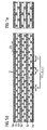
- Figure 1a shows a single individual layer 1A usable for a channel structure in accordance with the invention or for stacking on one another in the form of a foil from which a plurality of openings 3 are stamped out in the form of elongate apertures.
- the openings 3 are arranged in the foil, which is planar here, in the form of a two-dimensional matrix, that is, in the direction of columns and rows (with the direction of the columns being perpendicular to the direction of the rows).
- the individual openings 3 thus form a two-dimensional perforated grid, wherein a plurality of individual holes is arranged at regular, sequential intervals in the row direction (or in the direction of a first dimension D1 of the opening pattern 4) in every row.
- the direction of the longitudinal axis or the longitudinal direction of the openings 3 is identical to the dimension D1 here. Equally, a plurality of openings is arranged at regular intervals behind one another in the column direction (or in the direction of the second dimension D2 of the opening pattern standing perpendicular on the first dimension D1) in every column.
- two directly adjacent openings or elongate apertures 3 have the edge-to-edge spacing A (cf. Figure 1d ).
- the extent of an individual elongate aperture or of an opening 3 amounts to L1 in this longitudinal direction or direction of a first dimension D1 (cf. Figure 1d ).
- L1 3 ⁇ A in the present example.
- the center of mass spacing of two directly adjacent openings 3 thus equally has the value P1 in the direction of the first dimension D1.
- Figure 1a thus shows an individual layer 1A having precisely one layer section 2A1 in the form of a pattern 4 of elongate apertures 3 respectively regularly formed in the direction of the two dimensions D1, D2.
- Figure 1b now shows the already described individual layer 1A and a further, identically formed second individual layer 1B lying thereunder (only one individual layer section 2B1 is thus also realized in the second individual layer 1B having a plurality of openings 3 which are in turn formed in the layer plane of the individual layer 1B in the form of a pattern 4 respectively regular in two dimensions; these two dimensions of the second individual layer 1B coincide here with the two corresponding dimensions of the first individual layer 1A due to the arrangement over one another described below in more detail of the two individual layers 1A, 1B).
- the two identically formed individual layers or foils 1A, 1B are now arranged directly adjacent to one another with their layer planes parallel to one another, that is, stacked over one another in the direction perpendicular to the layer plane.
- This stacking is realized by an offset in the direction of the first dimension D1 (that is in the direction of the longitudinal axis of the individual openings).
- the two pattern matrices 4 of the upper layer 1A and of the lower layer 1B were in this respect offset by half a period P1 in the direction D1 relative to one another. No offset is realized in the direction perpendicular thereto (direction D2).
- a total of three identically formed individual layers are stacked over one another perpendicular to the respective layer plane.
- the bottommost layer 1A (having the individual layer section 2A1, which is formed over the total layer surface and whose pattern 4 and whose openings 3 are made as shown in Figure 1a ) and the topmost third layer 1C made identical to this layer 1A are stacked over one another with an offset by half a pattern period in the direction of the first dimension D1 and of the second dimension D2 (which are equally defined as shown in Figure 1 ).
- a mixer structure thus arises by introduction of a plane 1B rotated about 90° between two planes 1A, 1C made lengthwise (with respect to their channels or openings 3).
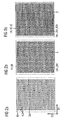
- Figure 2d shows a three-dimensional section through a real, correspondingly formed mixed structure in which then the topmost individual layer is covered by a closed layer 6a (sectional representation oblique due to said mixer structure). Further individual layers having opening structures adjoin beneath the bottommost of the three individual layers having aforesaid openings.
- Figure 2e shows a sectional representation lengthways through the channels 3 of the mixer structure formed as described above.
- Figure 3 shows a further example for a channel structure in accordance with the invention in the form of a helical structure which can be realized within the framework of a reactor construction.
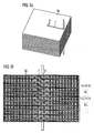
- Figure 3a shows a first individual layer 1A in the form of an LTCC ceramic.
- the first individual layer 1A here includes a total of four individual layer sections 2A1, 2A2, 2A3 and 2A4.
- the four layer sections are realized in that the first individual layer 1A, square here, is divided by its two diagonals d1, d2 into four isosceles, right-angled triangles which are identical with respect to their shapes, with one of the layer sections 2A1 to 2A4 corresponding to each of these triangles.
- Two respective oppositely disposed layer sections that is the layer section pair 2A1 and 2A3 as well as accordingly also the layer section pair 2A2 and 2A4) in this respect have an identical pattern of elongate apertures 3, wherein the directions of the longitudinal axis of each aperture 3 of a layer section pair are each aligned parallel to one another.
- the elongate apertures 3 of the sectional section pair 2A1, 2A3 thus all extend (with their longitudinal axes) in the direction of the first dimension D1 of the four patterns 4 of the layer sections 2A1 to 2A4 and all the elongate apertures of the layer section pair 2A2, 2A4 extend (with respect to the directions of their longitudinal axes) in the direction of the second dimension D2 of the regular patterns 4 of the four layer sections 2A1 to 2A4.
- all four layer sections 2A1 to 2A4 are completely filled with elongate apertures (whose shapes and sizes and whose spacings are here formed as described with respect to Figures 1 and 2 ), wherein the longitudinal axes of the elongate apertures are formed parallel to the triangle base of the respective layer sections.
- the elongate apertures of the sections 2A2 and 2A4 thus extend perpendicular to those of the layer sections 2A1 and 2A3, viewed with respect to their longitudinal axes.
- Figure 3b shows a further individual section 1B which is made identical with respect to its structuring to the individual layer 1A, but which is formed in the plane shown (which corresponds to that of the layer plane) rotated by 90° about the center of mass or the center S of the individual layer 1A. If the two dimensions D1, D2 of the second individual layer 1B are thus defined identically to that of the individual layer 1A, the opening structure of the individual layer 1B is thus rotated by 90° about the center of the individual layer 1A relative to the opening structure of the individual layer 1A.
- the apertures 3 of the second individual layer 1B are thus admittedly also aligned (viewed with respect to the direction of the longitudinal axes) in the two oppositely disposed layer sections 2B2 and 2B4 in the direction of the second dimension D2 and the apertures 3 of the two oppositely disposed layer sections 2B1 and 2B3 are aligned in the direction of the first dimension D1.
- the outermost aperture row of the layer sections 2A2 and 2A4 (or of the layer sections 2B1 and 2B3) facing the triangle basis respectively has one more aperture 3 than the outer aperture rows of the layer sections 2A1 and 2A3 (or 2B2 and 2B4) and since thus the hole structures in the two individual layers 1A, 1B are not mirror symmetrical to the diagonals d1 and d2, a respective offset results between apertures of the two individual layers 1A, 1B lying over one another on a stacking over one another of the two individual layers 1A, 1B:
- the individual openings of the two layers 1A, 1B thus do not lie identically above one another, but are rather only made partly overlapping so that twelve independent annular channels result in the overlap region 5 (viewed in the layer planes) which extend concentrically into one another and have a meander-like structure viewed in the section perpendicular to the layer planes (cf.
- Each of the twelve annular channels in this respect extends along the periphery of a square, wherein the side length of this square reduces in a linear manner from the outermost channel to the innermost channel (cf. Figure 3c ).
- Channels separate from one another having different lengths in the layer plane are thus produced by superimposition of a plurality of identical structures or individual layers laminated in an offset manner ( Figures 3a to 3d ).
- the twelve channels shown in Figure 3c and extending concentrically about a center are thus continued perpendicular to the layer planes so that a compact helical channel ducting arises by stacking a plurality of such individual layer triples shown in Figures 3a to 3d over one another (wherein respective suitable intermediate layers are formed which are respectively closed except for the passages 7, 8 into the next pair plane, cf. Figure 3f ), that is, by stacking perpendicular to the individual layer planes and by providing passages 7, 8 between the individual layers.
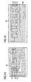
- the reformer here comprises, viewed in the layer plane, a plurality of individual blocks which are each connected to one another by channels conducted in two layers in the manner of a meander.
- FIG. 4 shows, complex channel structures can thus be realized in a manner in accordance with the invention so that the structures can represent the essential components of the reactors and/or reformers.
- the example reformer shown in this respect serves the reforming of ethanol.
- any desired channel structures can be produced, with the size and shape of the channels being limited only by the stamped tools used.
- a very compact construction is possible with the individual layer structure shown; for the insulation of individual channels, only an individual layer thickness is necessary (thickness e.g. 200 ⁇ m). Reaction surfaces of practically any desired size can be produced for the reforming.
- a channel structure in accordance with the present invention may be characterized in that at least one layer section of at least one individual layer has a pattern (4) regular in two dimensions (D1, D2) having a plurality of elongate apertures as openings, with the longitudinal axis of the elongate apertures being arranged in the direction of the first (D1) of the two dimensions and with the direction of the second dimension being perpendicular to the direction of the first dimension, that is, perpendicular to this longitudinal axis.
- the edge-to-edge spacing (A) can be smaller than or equal to half, particularly preferably equal to a third of the extent (L1) of the elongate apertures in the direction of their respective longitudinal axes; and/or the edge-to-edge spacing perpendicular to the direction of the first dimension, that is, the transverse direction, of at least two, preferably all elongate apertures arranged directly adjacent to one another in the direction of the second dimension (D2), that is, perpendicular to the direction of the first dimension (D1), can be equal to the edge-to-edge spacing (A) in the direction of the first dimension.
- At least two at least partly overlapping layer sections of two directly adjacent individual layers (1A, 1B, 1C) whose elongate apertures have the same shape and size and are arranged such that the elongate apertures of the layer section of the one individual layer are arranged rotated, preferably arranged rotated by 90°, relative to the elongate apertures of the layer section of the other individual layer can be provided.
Landscapes
- Chemical & Material Sciences (AREA)
- Engineering & Computer Science (AREA)
- Chemical Kinetics & Catalysis (AREA)
- General Engineering & Computer Science (AREA)
- Dispersion Chemistry (AREA)
- Organic Chemistry (AREA)
- Physics & Mathematics (AREA)
- Thermal Sciences (AREA)
- Health & Medical Sciences (AREA)
- Analytical Chemistry (AREA)
- Manufacturing & Machinery (AREA)
- Zoology (AREA)
- Mechanical Engineering (AREA)
- Life Sciences & Earth Sciences (AREA)
- Bioinformatics & Cheminformatics (AREA)
- Wood Science & Technology (AREA)
- Microbiology (AREA)
- Biotechnology (AREA)
- Sustainable Development (AREA)
- Biomedical Technology (AREA)
- Microelectronics & Electronic Packaging (AREA)
- Biochemistry (AREA)
- General Health & Medical Sciences (AREA)
- Genetics & Genomics (AREA)
- Physical Or Chemical Processes And Apparatus (AREA)
Claims (15)
- Kanalstruktur, die zur Verbindung mit und/oder zur Integration in einen Bioreaktor, einen biochemischen Reaktor, einen chemischen Reaktor und/oder einen Reformer einer elektrochemischen Zelle, insbesondere einer Brennstoffzelle, eines Akkus oder einer Batterie ausgelegt ist, umfassend
mehrere einzelne Schichten (1A, 1B, 1C), die aufeinander gestapelt sind, wobei die einzelnen Schichten jeweils mehrere Auslassungen (3) aufweisen, die vollständig durch die jeweilige einzelne Schicht treten, und wobei direkt benachbarte einzelne Schichten jeweils aneinander angrenzend angeordnet sind und/oder miteinander verbunden sind,
wobei mindestens zwei direkt benachbarte einzelne Schichten (1A, 1B, 1C) jeweils mindestens einen Schichtabschnitt (2A1, 2A2, ...., 2B1, 2B2,...) aufweisen, dessen Auslassungen (3) - in der jeweiligen Schichtfläche gesehen - in der Form eines Musters (4) angeordnet sind, das jeweils in zwei Abmessungen (D1, D2) regelmäßig ist, und
wobei mindestens zwei der Schichtabschnitte von direkt benachbarten einzelnen Schichten, die mit einem solchen Muster (4) versehen sind, in den Schichtflächen dieser einzelnen Schichten gesehen - zumindest teilweise überlappen (5), wobei die Auslassungen der zwei mindestens teilweise überlappenden Schichtabschnitte - in den Schichtflächen dieser einzelnen Schichten gesehen - in dem Überlappungsbereich (5) relativ zueinander gedreht und/oder versetzt sind,
dadurch gekennzeichnet, dass
die Muster (4) der zwei mindestens teilweise überlappenden Schichtabschnitte, deren Auslassungen (3) relativ zueinander gedreht und/oder versetzt sind, mit Ausnahme der Drehung und/oder des Versatzes identisch ausgelegt sind. - Kanalstruktur nach dem vorhergehenden Anspruch,
dadurch gekennzeichnet ist, dass
die Auslassungen (3) eines Schichtabschnitts oder mehrerer Schichtabschnitte (2A1, 2A2, ..., 2B1, 2B2, ...) einer oder mehrerer einzelner Schicht(en) jeweils eine bevorzugte Richtung aufweisen, d.h. in der jeweiligen Schichtfläche in einer ersten räumlichen Richtung, die anschließend auch als Längsrichtung bezeichnet wird, eine größere oder kleinere Erstreckung als in einer zweiten räumlichen Richtung, die ungleich der ersten räumlichen Richtung in dieser Schichtfläche ist, haben. - Kanalstruktur nach dem vorhergehenden Anspruch,
dadurch gekennzeichnet, dass
die erste räumliche Richtung die Richtung der ersten (D1) oder der zweiten (D2) der zwei Abmessungen (D1, D2) des regelmäßigen Musters (4) eines Schichtabschnitts einer einzelnen Schicht ist. - Kanalstruktur nach einem der vorhergehenden Ansprüche,
dadurch gekennzeichnet, dass
eine oder mehrere einzelne Schicht(en) (1A, 1B, 1C) mehrere Schichtabschnitte (2A1, 2A2, ..., 2B1, 2B2, ...) aufweist/aufweisen, so dass die Auslassungen (3) von mindestens zwei Schichtabschnitten von ein und derselben einzelnen Schicht - in der Schichtfläche gesehen - in der Form von Mustern (4) angeordnet sind, die jeweils in zwei Abmessungen (D1, D2) regelmäßig sind, und wobei sie mindestens eine nicht übereinstimmende Abmessungsrichtung haben und/oder unterschiedliche bevorzugte Richtungen haben. - Kanalstruktur nach einem der vorhergehenden Ansprüche,
gekennzeichnet durch
mindestens zwei direkt benachbarte einzelne Schichten (1A, 1B, 1C), die jeweils mehrere Schichtabschnitte mit Auslassungen (3) in der Form eines Musters (4) haben, das in zwei Abmessungen jeweils regelmäßig ist, wobei mehrere Schichtabschnitte von zwei solchen direkt benachbarten einzelnen Schichten sich jeweils paarweise mindestens teilweise überlappen, so dass die Auslassungen des einen Schichtabschnitts eines überlappenden Schichtabschnittpaars zu den Auslassungen des anderen Schichtabschnitts dieses überlappenden Schichtabschnittpaars gedreht und/oder versetzt angeordnet sind. - Kanalstruktur nach einem der vorhergehenden Ansprüche,
dadurch gekennzeichnet, dass
die Auslassungen von mindestens zwei teilweise überlappenden Schichtabschnitten von zwei direkt benachbarten einzelnen Schichten (1A, 1B, 1C) zumindest teilweise in ihrem Überlappungsbereich (5) so angeordnet sind, dass zwischen Auslassungen der zwei direkt benachbarten einzelnen Schichten (1A, 1B, 1C) offene Verbindungen, d.h. Durchströmmöglichkeiten, von einer Auslassung der einen dieser zwei direkt benachbarten einzelnen Schichten (1A, 1B, 1C) zu einer Auslassung der anderen dieser zwei direkt benachbarten einzelnen Schichten trotz eines Versatzes und/oder einer Drehung der Auslassungen relativ zueinander ausgebildet sind. - Kanalstruktur nach einem der vorhergehenden Ansprüche,
gekennzeichnet durch
mindestens ein Überlappungsbereich (5), in dem die Auslassungen der überlappenden Schichtabschnitte von zwei direkt benachbarten einzelnen Schichten (1A, 1B, 1C) relativ zueinander gedreht sind, aber nicht relativ zueinander versetzt sind. - Kanalstruktur nach einem der vorhergehenden Ansprüche,
gekennzeichnet durch
mindestens einen Überlappungsbereich (5), in dem die Auslassungen der überlappenden Schichtabschnitte von zwei direkt benachbarten einzelnen Schichten (1A, 1B, 1C) relativ zueinander versetzt sind, aber nicht relativ zu einander gedreht sind. - Kanalstruktur nach einem der vorhergehenden Ansprüche,
gekennzeichnet durch
mindestens ein Muster (4), das in zwei Abmessungen (D1, D2) regelmäßig ist, mit mehreren Auslassungen, die in der Form einer zweidimensionalen Matrix in Zeilen und Spalten angeordnet sind, wobei die Zeilenrichtung senkrecht zu der Spaltenrichtung ist. - Kanalstruktur nach einem der vorhergehenden Ansprüche,
dadurch gekennzeichnet, dass
mindestens zwei direkt benachbarte einzelne Schichten (1A, 1B, 1C) bezüglich ihrer Schichtabschnitte, ihrer Muster und ihrer Auslassungen identisch ausgelegt sind und - in den Schichtflächen dieser einzelnen Schichten gesehen - relativ zueinander gedreht und/oder relativ zueinander versetzt angeordnet sind. - Kanalstruktur nach dem vorhergehenden Anspruch,
dadurch gekennzeichnet, dass
die zwei einzelnen Schichten relativ zueinander versetzt, aber nicht relativ zueinander gedreht angeordnet sind;
oder
dass die zwei einzelnen Schichten relativ zueinander gedreht, aber nicht relativ zueinander versetzt angeordnet sind. - Kanalstruktur nach einem der vorhergehenden Ansprüche,
dadurch gekennzeichnet, dass
die Auslassung (3) von mehreren von jeweils direkt benachbarten einzelnen Schichten (1A, 1B, 1C) und/oder Schichtabschnitten (2A1, 2A2, ..., 2B1, 2B2, ...) sich jeweils nur teilweise überlappen. - Bioreaktor, biochemischer Reaktor, chemischer Reaktor, Reformer einer elektrochemischen Zelle oder Wärmetauscher,
gekennzeichnet durch
mindestens eine angeschlossene und/oder integrierte Kanalstruktur nach einem der vorhergehenden Ansprüche; und/oder dass der Reaktor, der Reformer oder der Wärmetauscher als Kanalstruktur nach einem der vorhergehenden Ansprüche ausgelegt ist. - Bioreaktor, biochemischer Reaktor, chemischer Reaktor, Reformer einer elektrochemischen Zelle oder Wärmetauscher nach dem vorhergehenden Anspruch, wobei der gesamte Bioreaktor, biochemische Reaktor, chemische Reaktor, Reformer oder Wärmetauscher nur aus mehreren einzelnen Schichten (1A, 1B, 1C), die aufeinander gestapelt sind, ihren Schichtabschnitten (2A1, 2A2, ..., 2B1, 2B2, ...), ihren Mustern (4) und ihren Auslassungen (3) bestehen.
- Verwendung einer Kanalstruktur nach einem der vorhergehenden Ansprüche zum Zuführen einer Flüssigkeit oder mehrerer Flüssigkeiten, eines Gases oder mehrerer Gase und/oder eines Pulvers oder mehrerer Pulver zu einem Bioreaktor, einem biochemischen Reaktor, einem chemischen Reaktor oder einem Reformer einer elektrochemischen Zelle; und/oder zum Mischen von mehreren Flüssigkeiten und/oder mehreren Gasen in einem Bioreaktor, einem biochemischen Reaktor, einem chemischen Reaktor oder einem Reformer einer elektrochemischen Zelle; und/oder für den Transport von Material und/oder Wärme.
Applications Claiming Priority (2)
| Application Number | Priority Date | Filing Date | Title |
|---|---|---|---|
| DE200910038019 DE102009038019B4 (de) | 2009-08-12 | 2009-08-12 | 3D Mikro-Strukturierung zur Erzeugung von Misch- und Kanalstrukturen in Multilayertechnologie zur Verwendung in oder zum Aufbau von Reaktoren |
| PCT/EP2010/004899 WO2011018213A1 (en) | 2009-08-12 | 2010-08-11 | 3d microstructuring for generating mixed structures and channel structures in multilayer technology for use in or for the construction of reactors |
Publications (2)
| Publication Number | Publication Date |
|---|---|
| EP2464448A1 EP2464448A1 (de) | 2012-06-20 |
| EP2464448B1 true EP2464448B1 (de) | 2013-10-09 |
Family
ID=43063487
Family Applications (1)
| Application Number | Title | Priority Date | Filing Date |
|---|---|---|---|
| EP20100744519 Ceased EP2464448B1 (de) | 2009-08-12 | 2010-08-11 | 3d-mikrostrukturierung zur herstellung von mischstrukturen und kanalstrukturen in einer mehrschichttechnologie zur verwendung für reaktoren oder für den bau von reaktoren |
Country Status (4)
| Country | Link |
|---|---|
| US (1) | US20120208265A1 (de) |
| EP (1) | EP2464448B1 (de) |
| DE (1) | DE102009038019B4 (de) |
| WO (1) | WO2011018213A1 (de) |
Families Citing this family (19)
| Publication number | Priority date | Publication date | Assignee | Title |
|---|---|---|---|---|
| CN102188944B (zh) * | 2011-05-16 | 2013-08-28 | 利穗科技(苏州)有限公司 | 一种混沌型多级涡流微反应器 |
| DE102012021603A1 (de) * | 2012-06-28 | 2014-01-23 | Philipp Comanns | Strukturierung bzw. Anordnung von Oberflächen zum gerichteten Transport von Flüssigkeiten in Kapillaren |
| CN103305812A (zh) * | 2013-06-08 | 2013-09-18 | 上海和辉光电有限公司 | 一种上电极装置 |
| CN103285798B (zh) * | 2013-06-27 | 2015-04-22 | 利穗科技(苏州)有限公司 | 一种多层多级微反应器 |
| JP6190349B2 (ja) * | 2013-12-05 | 2017-08-30 | 株式会社神戸製鋼所 | 熱交換器 |
| US11859914B2 (en) * | 2015-01-22 | 2024-01-02 | Pimems, Inc. | High performance two-phase cooling apparatus |
| EP3332255B1 (de) | 2015-08-06 | 2020-06-17 | Lia Diagnostics, Inc. | Wasserdispergierbare tests |
| SG11201809805WA (en) | 2016-05-05 | 2018-12-28 | Southwest Res Inst | Three-dimensional bioreactor for cell expansion and related applications |
| JP6400240B1 (ja) * | 2018-02-05 | 2018-10-03 | 新光電気工業株式会社 | ループ型ヒートパイプ及びその製造方法 |
| JP6995673B2 (ja) * | 2018-03-16 | 2022-01-14 | 新光電気工業株式会社 | ループ型ヒートパイプ |
| JP7015197B2 (ja) * | 2018-03-26 | 2022-02-02 | 新光電気工業株式会社 | ループ型ヒートパイプ及びその製造方法 |
| US11149244B2 (en) | 2018-04-04 | 2021-10-19 | Southwest Research Institute | Three-dimensional bioreactor for T-cell activation and expansion for immunotherapy |
| SG11202102986XA (en) | 2018-09-24 | 2021-04-29 | Southwest Res Inst | Three-dimensional bioreactors |
| JP7197346B2 (ja) * | 2018-12-19 | 2022-12-27 | 新光電気工業株式会社 | ループ型ヒートパイプ |
| WO2021030245A1 (en) * | 2019-08-12 | 2021-02-18 | Waters Technologies Corporation | Mixer for chromatography system |
| US11492580B2 (en) | 2020-05-12 | 2022-11-08 | Southwest Research Institute | Method using a three-dimensional bioprocessor |
| AU2022377625B2 (en) | 2021-10-28 | 2025-01-02 | Southwest Research Institute | Devices for cell separation |
| CN115178168B (zh) * | 2022-07-11 | 2024-02-09 | 兖矿鲁南化工有限公司 | 一种羰基化浆态气液混合器及使用方法 |
| TW202545258A (zh) * | 2024-05-07 | 2025-11-16 | 華碩電腦股份有限公司 | 電子裝置之機殼 |
Family Cites Families (15)
| Publication number | Priority date | Publication date | Assignee | Title |
|---|---|---|---|---|
| US3856270A (en) * | 1973-10-09 | 1974-12-24 | Fmc Corp | Static fluid mixing apparatus |
| US5327941A (en) * | 1992-06-16 | 1994-07-12 | The United States Of America As Represented By The Secretary Of The Navy | Cascade orificial resistive device |
| DE4235979A1 (de) * | 1992-10-24 | 1994-04-28 | Basf Ag | Verfahren und Vorrichtung zum Mischen von Polymerlösungen |
| US5980596A (en) * | 1997-04-25 | 1999-11-09 | Exxon Research And Engineering Co. | Multi-injector autothermal reforming process and apparatus for producing synthesis gas (law 565). |
| DE19927556C2 (de) * | 1999-06-16 | 2003-05-08 | Inst Mikrotechnik Mainz Gmbh | Statischer Mikromischer und Verfahren zum statischen Mischen zweier oder mehrerer Edukte |
| DE19927554C2 (de) * | 1999-06-16 | 2002-12-19 | Inst Mikrotechnik Mainz Gmbh | Mikromischer |
| DE10055374B4 (de) | 2000-11-08 | 2006-03-02 | Bartels Mikrotechnik Gmbh | Verteilerplatte für Flüssigkeiten und Gase |
| WO2002089989A1 (en) * | 2001-05-07 | 2002-11-14 | Epcon Co., Ltd. | Mixing, crushing, and pulverizing device, and method of pulverizing substances using the device |
| US7883670B2 (en) * | 2002-02-14 | 2011-02-08 | Battelle Memorial Institute | Methods of making devices by stacking sheets and processes of conducting unit operations using such devices |
| US20040226620A1 (en) * | 2002-09-26 | 2004-11-18 | Daniel Therriault | Microcapillary networks |
| SE524540C2 (sv) * | 2002-11-18 | 2004-08-24 | Alfa Laval Corp Ab | Flödesstyrande insats i en reaktorkammare samt reaktor försedd med insatsen |
| DE20218972U1 (de) * | 2002-12-07 | 2003-02-13 | Ehrfeld Mikrotechnik AG, 55234 Wendelsheim | Statischer Laminationsmikrovermischer |
| JP4352704B2 (ja) * | 2003-01-09 | 2009-10-28 | 日産自動車株式会社 | 一酸化炭素除去装置 |
| DE20304101U1 (de) * | 2003-03-14 | 2003-05-22 | Ehrfeld Mikrotechnik AG, 55234 Wendelsheim | Mikrovermischer mit integriertem Wärmetauscher |
| EP1629068A4 (de) * | 2003-05-16 | 2011-08-24 | Battelle Memorial Institute | Schnellstart-brennstoffreformationssysteme und methoden |
-
2009
- 2009-08-12 DE DE200910038019 patent/DE102009038019B4/de not_active Expired - Fee Related
-
2010
- 2010-08-11 WO PCT/EP2010/004899 patent/WO2011018213A1/en not_active Ceased
- 2010-08-11 US US13/390,159 patent/US20120208265A1/en not_active Abandoned
- 2010-08-11 EP EP20100744519 patent/EP2464448B1/de not_active Ceased
Also Published As
| Publication number | Publication date |
|---|---|
| WO2011018213A1 (en) | 2011-02-17 |
| EP2464448A1 (de) | 2012-06-20 |
| DE102009038019A1 (de) | 2011-04-21 |
| US20120208265A1 (en) | 2012-08-16 |
| DE102009038019B4 (de) | 2011-11-17 |
Similar Documents
| Publication | Publication Date | Title |
|---|---|---|
| US20120208265A1 (en) | 3d microstructuring for generating mixed structures and channel structures in multilayer technology for use in or for the construction of reactors | |
| EP1623761B1 (de) | Mikrokanal-Vorichtungen hergestellt durch Aufstapeln von Schichten | |
| US7455925B2 (en) | Thin-layer fuel cell structure | |
| US4934453A (en) | Heat exchanger module of fired ceramic material | |
| WO1999064146A1 (de) | Verfahren zur herstellung eines kompakten katalytischen reaktors | |
| US9643288B2 (en) | Heat exchange reactor using thin plate provided with flow path therein and method of manufacturing the same | |
| RU2001100070A (ru) | Газоотделитель для топливных элементов | |
| WO2004099696A1 (en) | Heat exchanger core | |
| US20040194939A1 (en) | Plate-type heat exchanger | |
| JP4553193B2 (ja) | プレートを形成する方法 | |
| Belavic et al. | Design of LTCC-based Ceramic Structure for Chemical Microreactor. | |
| JP2006513064A5 (de) | ||
| JP2006122735A (ja) | 流路構造体および流体混合装置 | |
| JPS5933014B2 (ja) | 流体部位の変換素子 | |
| US7655341B2 (en) | Bipolar plate for fuel cells, which is formed from a shaped foil, and method for manufacturing same | |
| JP2009119447A (ja) | 積層多孔構造体 | |
| US8659371B2 (en) | Three-dimensional matrix structure for defining a coaxial transmission line channel | |
| KR101849540B1 (ko) | 반응기 및 열교환기용 체널형 스텍 및 그 제조 방법 | |
| JP2018141602A (ja) | マイクロ流路熱交換器 | |
| KR20200034316A (ko) | 인쇄기판형 열교환기 및 이를 포함하는 열교환 장치 | |
| CN107851827B (zh) | 用于制造燃料电池的双极板的堆叠 | |
| WO2014159555A1 (en) | Reactor incorporating a heat exchanger | |
| KR20060072674A (ko) | 3차원 미세채널을 이용한 미세채널 반응기 | |
| Brandner et al. | Comparison of crossflow micro heat exchangers with different microstructure designs | |
| KR101072686B1 (ko) | 내부에 격벽을 가진 3차원 트러스 타입의 주기적인 다공질 재료 및 그의 제조방법 |
Legal Events
| Date | Code | Title | Description |
|---|---|---|---|
| PUAI | Public reference made under article 153(3) epc to a published international application that has entered the european phase |
Free format text: ORIGINAL CODE: 0009012 |
|
| 17P | Request for examination filed |
Effective date: 20120307 |
|
| AK | Designated contracting states |
Kind code of ref document: A1 Designated state(s): AL AT BE BG CH CY CZ DE DK EE ES FI FR GB GR HR HU IE IS IT LI LT LU LV MC MK MT NL NO PL PT RO SE SI SK SM TR |
|
| DAX | Request for extension of the european patent (deleted) | ||
| GRAP | Despatch of communication of intention to grant a patent |
Free format text: ORIGINAL CODE: EPIDOSNIGR1 |
|
| INTG | Intention to grant announced |
Effective date: 20130404 |
|
| GRAS | Grant fee paid |
Free format text: ORIGINAL CODE: EPIDOSNIGR3 |
|
| GRAA | (expected) grant |
Free format text: ORIGINAL CODE: 0009210 |
|
| AK | Designated contracting states |
Kind code of ref document: B1 Designated state(s): AL AT BE BG CH CY CZ DE DK EE ES FI FR GB GR HR HU IE IS IT LI LT LU LV MC MK MT NL NO PL PT RO SE SI SK SM TR |
|
| REG | Reference to a national code |
Ref country code: GB Ref legal event code: FG4D |
|
| REG | Reference to a national code |
Ref country code: CH Ref legal event code: EP Ref country code: AT Ref legal event code: REF Ref document number: 635316 Country of ref document: AT Kind code of ref document: T Effective date: 20131015 |
|
| REG | Reference to a national code |
Ref country code: IE Ref legal event code: FG4D |
|
| REG | Reference to a national code |
Ref country code: DE Ref legal event code: R096 Ref document number: 602010010847 Country of ref document: DE Effective date: 20131205 |
|
| REG | Reference to a national code |
Ref country code: AT Ref legal event code: MK05 Ref document number: 635316 Country of ref document: AT Kind code of ref document: T Effective date: 20131009 |
|
| REG | Reference to a national code |
Ref country code: NL Ref legal event code: VDEP Effective date: 20131009 |
|
| PG25 | Lapsed in a contracting state [announced via postgrant information from national office to epo] |
Ref country code: SI Free format text: LAPSE BECAUSE OF FAILURE TO SUBMIT A TRANSLATION OF THE DESCRIPTION OR TO PAY THE FEE WITHIN THE PRESCRIBED TIME-LIMIT Effective date: 20131009 |
|
| REG | Reference to a national code |
Ref country code: LT Ref legal event code: MG4D |
|
| PG25 | Lapsed in a contracting state [announced via postgrant information from national office to epo] |
Ref country code: NL Free format text: LAPSE BECAUSE OF FAILURE TO SUBMIT A TRANSLATION OF THE DESCRIPTION OR TO PAY THE FEE WITHIN THE PRESCRIBED TIME-LIMIT Effective date: 20131009 Ref country code: SE Free format text: LAPSE BECAUSE OF FAILURE TO SUBMIT A TRANSLATION OF THE DESCRIPTION OR TO PAY THE FEE WITHIN THE PRESCRIBED TIME-LIMIT Effective date: 20131009 Ref country code: FI Free format text: LAPSE BECAUSE OF FAILURE TO SUBMIT A TRANSLATION OF THE DESCRIPTION OR TO PAY THE FEE WITHIN THE PRESCRIBED TIME-LIMIT Effective date: 20131009 Ref country code: NO Free format text: LAPSE BECAUSE OF FAILURE TO SUBMIT A TRANSLATION OF THE DESCRIPTION OR TO PAY THE FEE WITHIN THE PRESCRIBED TIME-LIMIT Effective date: 20140109 Ref country code: HR Free format text: LAPSE BECAUSE OF FAILURE TO SUBMIT A TRANSLATION OF THE DESCRIPTION OR TO PAY THE FEE WITHIN THE PRESCRIBED TIME-LIMIT Effective date: 20131009 Ref country code: LT Free format text: LAPSE BECAUSE OF FAILURE TO SUBMIT A TRANSLATION OF THE DESCRIPTION OR TO PAY THE FEE WITHIN THE PRESCRIBED TIME-LIMIT Effective date: 20131009 Ref country code: IS Free format text: LAPSE BECAUSE OF FAILURE TO SUBMIT A TRANSLATION OF THE DESCRIPTION OR TO PAY THE FEE WITHIN THE PRESCRIBED TIME-LIMIT Effective date: 20140209 Ref country code: BE Free format text: LAPSE BECAUSE OF FAILURE TO SUBMIT A TRANSLATION OF THE DESCRIPTION OR TO PAY THE FEE WITHIN THE PRESCRIBED TIME-LIMIT Effective date: 20131009 |
|
| PG25 | Lapsed in a contracting state [announced via postgrant information from national office to epo] |
Ref country code: LV Free format text: LAPSE BECAUSE OF FAILURE TO SUBMIT A TRANSLATION OF THE DESCRIPTION OR TO PAY THE FEE WITHIN THE PRESCRIBED TIME-LIMIT Effective date: 20131009 Ref country code: AT Free format text: LAPSE BECAUSE OF FAILURE TO SUBMIT A TRANSLATION OF THE DESCRIPTION OR TO PAY THE FEE WITHIN THE PRESCRIBED TIME-LIMIT Effective date: 20131009 Ref country code: ES Free format text: LAPSE BECAUSE OF FAILURE TO SUBMIT A TRANSLATION OF THE DESCRIPTION OR TO PAY THE FEE WITHIN THE PRESCRIBED TIME-LIMIT Effective date: 20131009 Ref country code: CY Free format text: LAPSE BECAUSE OF FAILURE TO SUBMIT A TRANSLATION OF THE DESCRIPTION OR TO PAY THE FEE WITHIN THE PRESCRIBED TIME-LIMIT Effective date: 20131009 Ref country code: PL Free format text: LAPSE BECAUSE OF FAILURE TO SUBMIT A TRANSLATION OF THE DESCRIPTION OR TO PAY THE FEE WITHIN THE PRESCRIBED TIME-LIMIT Effective date: 20131009 |
|
| PG25 | Lapsed in a contracting state [announced via postgrant information from national office to epo] |
Ref country code: PT Free format text: LAPSE BECAUSE OF FAILURE TO SUBMIT A TRANSLATION OF THE DESCRIPTION OR TO PAY THE FEE WITHIN THE PRESCRIBED TIME-LIMIT Effective date: 20140210 |
|
| REG | Reference to a national code |
Ref country code: DE Ref legal event code: R097 Ref document number: 602010010847 Country of ref document: DE |
|
| PG25 | Lapsed in a contracting state [announced via postgrant information from national office to epo] |
Ref country code: EE Free format text: LAPSE BECAUSE OF FAILURE TO SUBMIT A TRANSLATION OF THE DESCRIPTION OR TO PAY THE FEE WITHIN THE PRESCRIBED TIME-LIMIT Effective date: 20131009 |
|
| PLBE | No opposition filed within time limit |
Free format text: ORIGINAL CODE: 0009261 |
|
| STAA | Information on the status of an ep patent application or granted ep patent |
Free format text: STATUS: NO OPPOSITION FILED WITHIN TIME LIMIT |
|
| PG25 | Lapsed in a contracting state [announced via postgrant information from national office to epo] |
Ref country code: RO Free format text: LAPSE BECAUSE OF FAILURE TO SUBMIT A TRANSLATION OF THE DESCRIPTION OR TO PAY THE FEE WITHIN THE PRESCRIBED TIME-LIMIT Effective date: 20131009 Ref country code: CZ Free format text: LAPSE BECAUSE OF FAILURE TO SUBMIT A TRANSLATION OF THE DESCRIPTION OR TO PAY THE FEE WITHIN THE PRESCRIBED TIME-LIMIT Effective date: 20131009 Ref country code: SK Free format text: LAPSE BECAUSE OF FAILURE TO SUBMIT A TRANSLATION OF THE DESCRIPTION OR TO PAY THE FEE WITHIN THE PRESCRIBED TIME-LIMIT Effective date: 20131009 |
|
| 26N | No opposition filed |
Effective date: 20140710 |
|
| PG25 | Lapsed in a contracting state [announced via postgrant information from national office to epo] |
Ref country code: DK Free format text: LAPSE BECAUSE OF FAILURE TO SUBMIT A TRANSLATION OF THE DESCRIPTION OR TO PAY THE FEE WITHIN THE PRESCRIBED TIME-LIMIT Effective date: 20131009 |
|
| REG | Reference to a national code |
Ref country code: DE Ref legal event code: R097 Ref document number: 602010010847 Country of ref document: DE Effective date: 20140710 |
|
| PG25 | Lapsed in a contracting state [announced via postgrant information from national office to epo] |
Ref country code: MC Free format text: LAPSE BECAUSE OF FAILURE TO SUBMIT A TRANSLATION OF THE DESCRIPTION OR TO PAY THE FEE WITHIN THE PRESCRIBED TIME-LIMIT Effective date: 20131009 Ref country code: LU Free format text: LAPSE BECAUSE OF FAILURE TO SUBMIT A TRANSLATION OF THE DESCRIPTION OR TO PAY THE FEE WITHIN THE PRESCRIBED TIME-LIMIT Effective date: 20140811 |
|
| REG | Reference to a national code |
Ref country code: CH Ref legal event code: PL |
|
| PG25 | Lapsed in a contracting state [announced via postgrant information from national office to epo] |
Ref country code: CH Free format text: LAPSE BECAUSE OF NON-PAYMENT OF DUE FEES Effective date: 20140831 Ref country code: LI Free format text: LAPSE BECAUSE OF NON-PAYMENT OF DUE FEES Effective date: 20140831 |
|
| PG25 | Lapsed in a contracting state [announced via postgrant information from national office to epo] |
Ref country code: IE Free format text: LAPSE BECAUSE OF NON-PAYMENT OF DUE FEES Effective date: 20140811 |
|
| PG25 | Lapsed in a contracting state [announced via postgrant information from national office to epo] |
Ref country code: SM Free format text: LAPSE BECAUSE OF FAILURE TO SUBMIT A TRANSLATION OF THE DESCRIPTION OR TO PAY THE FEE WITHIN THE PRESCRIBED TIME-LIMIT Effective date: 20131009 |
|
| PG25 | Lapsed in a contracting state [announced via postgrant information from national office to epo] |
Ref country code: BG Free format text: LAPSE BECAUSE OF FAILURE TO SUBMIT A TRANSLATION OF THE DESCRIPTION OR TO PAY THE FEE WITHIN THE PRESCRIBED TIME-LIMIT Effective date: 20131009 Ref country code: MT Free format text: LAPSE BECAUSE OF FAILURE TO SUBMIT A TRANSLATION OF THE DESCRIPTION OR TO PAY THE FEE WITHIN THE PRESCRIBED TIME-LIMIT Effective date: 20131009 Ref country code: GR Free format text: LAPSE BECAUSE OF FAILURE TO SUBMIT A TRANSLATION OF THE DESCRIPTION OR TO PAY THE FEE WITHIN THE PRESCRIBED TIME-LIMIT Effective date: 20140110 |
|
| PG25 | Lapsed in a contracting state [announced via postgrant information from national office to epo] |
Ref country code: HU Free format text: LAPSE BECAUSE OF FAILURE TO SUBMIT A TRANSLATION OF THE DESCRIPTION OR TO PAY THE FEE WITHIN THE PRESCRIBED TIME-LIMIT; INVALID AB INITIO Effective date: 20100811 Ref country code: TR Free format text: LAPSE BECAUSE OF FAILURE TO SUBMIT A TRANSLATION OF THE DESCRIPTION OR TO PAY THE FEE WITHIN THE PRESCRIBED TIME-LIMIT Effective date: 20131009 |
|
| REG | Reference to a national code |
Ref country code: FR Ref legal event code: PLFP Year of fee payment: 7 |
|
| REG | Reference to a national code |
Ref country code: FR Ref legal event code: PLFP Year of fee payment: 8 |
|
| PG25 | Lapsed in a contracting state [announced via postgrant information from national office to epo] |
Ref country code: MK Free format text: LAPSE BECAUSE OF FAILURE TO SUBMIT A TRANSLATION OF THE DESCRIPTION OR TO PAY THE FEE WITHIN THE PRESCRIBED TIME-LIMIT Effective date: 20131009 |
|
| REG | Reference to a national code |
Ref country code: FR Ref legal event code: PLFP Year of fee payment: 9 |
|
| PG25 | Lapsed in a contracting state [announced via postgrant information from national office to epo] |
Ref country code: AL Free format text: LAPSE BECAUSE OF FAILURE TO SUBMIT A TRANSLATION OF THE DESCRIPTION OR TO PAY THE FEE WITHIN THE PRESCRIBED TIME-LIMIT Effective date: 20131009 |
|
| PGFP | Annual fee paid to national office [announced via postgrant information from national office to epo] |
Ref country code: TR Payment date: 20180703 Year of fee payment: 16 Ref country code: FR Payment date: 20180824 Year of fee payment: 9 |
|
| PGFP | Annual fee paid to national office [announced via postgrant information from national office to epo] |
Ref country code: GB Payment date: 20180828 Year of fee payment: 9 |
|
| GBPC | Gb: european patent ceased through non-payment of renewal fee |
Effective date: 20190811 |
|
| PG25 | Lapsed in a contracting state [announced via postgrant information from national office to epo] |
Ref country code: FR Free format text: LAPSE BECAUSE OF NON-PAYMENT OF DUE FEES Effective date: 20190831 |
|
| PG25 | Lapsed in a contracting state [announced via postgrant information from national office to epo] |
Ref country code: GB Free format text: LAPSE BECAUSE OF NON-PAYMENT OF DUE FEES Effective date: 20190811 Ref country code: IT Free format text: LAPSE BECAUSE OF NON-PAYMENT OF DUE FEES Effective date: 20190811 |
|
| PGFP | Annual fee paid to national office [announced via postgrant information from national office to epo] |
Ref country code: DE Payment date: 20200824 Year of fee payment: 11 |
|
| REG | Reference to a national code |
Ref country code: DE Ref legal event code: R079 Ref document number: 602010010847 Country of ref document: DE Free format text: PREVIOUS MAIN CLASS: B01F0013000000 Ipc: B01F0033000000 |
|
| REG | Reference to a national code |
Ref country code: DE Ref legal event code: R119 Ref document number: 602010010847 Country of ref document: DE |
|
| PG25 | Lapsed in a contracting state [announced via postgrant information from national office to epo] |
Ref country code: DE Free format text: LAPSE BECAUSE OF NON-PAYMENT OF DUE FEES Effective date: 20220301 |