EP2464207B1 - Agricultural funicular traction system with electric propulsion - Google Patents
Agricultural funicular traction system with electric propulsion Download PDFInfo
- Publication number
- EP2464207B1 EP2464207B1 EP10763039.4A EP10763039A EP2464207B1 EP 2464207 B1 EP2464207 B1 EP 2464207B1 EP 10763039 A EP10763039 A EP 10763039A EP 2464207 B1 EP2464207 B1 EP 2464207B1
- Authority
- EP
- European Patent Office
- Prior art keywords
- working
- agricultural
- tractor
- machine
- electric propulsion
- Prior art date
- Legal status (The legal status is an assumption and is not a legal conclusion. Google has not performed a legal analysis and makes no representation as to the accuracy of the status listed.)
- Not-in-force
Links
Images





Classifications
-
- A—HUMAN NECESSITIES
- A01—AGRICULTURE; FORESTRY; ANIMAL HUSBANDRY; HUNTING; TRAPPING; FISHING
- A01B—SOIL WORKING IN AGRICULTURE OR FORESTRY; PARTS, DETAILS, OR ACCESSORIES OF AGRICULTURAL MACHINES OR IMPLEMENTS, IN GENERAL
- A01B3/00—Ploughs with fixed plough-shares
- A01B3/64—Cable ploughs; Indicating or signalling devices for cable plough systems
-
- A—HUMAN NECESSITIES
- A01—AGRICULTURE; FORESTRY; ANIMAL HUSBANDRY; HUNTING; TRAPPING; FISHING
- A01B—SOIL WORKING IN AGRICULTURE OR FORESTRY; PARTS, DETAILS, OR ACCESSORIES OF AGRICULTURAL MACHINES OR IMPLEMENTS, IN GENERAL
- A01B69/00—Steering of agricultural machines or implements; Guiding agricultural machines or implements on a desired track
- A01B69/007—Steering or guiding of agricultural vehicles, e.g. steering of the tractor to keep the plough in the furrow
- A01B69/008—Steering or guiding of agricultural vehicles, e.g. steering of the tractor to keep the plough in the furrow automatic
-
- B—PERFORMING OPERATIONS; TRANSPORTING
- B60—VEHICLES IN GENERAL
- B60L—PROPULSION OF ELECTRICALLY-PROPELLED VEHICLES; SUPPLYING ELECTRIC POWER FOR AUXILIARY EQUIPMENT OF ELECTRICALLY-PROPELLED VEHICLES; ELECTRODYNAMIC BRAKE SYSTEMS FOR VEHICLES IN GENERAL; MAGNETIC SUSPENSION OR LEVITATION FOR VEHICLES; MONITORING OPERATING VARIABLES OF ELECTRICALLY-PROPELLED VEHICLES; ELECTRIC SAFETY DEVICES FOR ELECTRICALLY-PROPELLED VEHICLES
- B60L9/00—Electric propulsion with power supply external to the vehicle
-
- B—PERFORMING OPERATIONS; TRANSPORTING
- B60—VEHICLES IN GENERAL
- B60L—PROPULSION OF ELECTRICALLY-PROPELLED VEHICLES; SUPPLYING ELECTRIC POWER FOR AUXILIARY EQUIPMENT OF ELECTRICALLY-PROPELLED VEHICLES; ELECTRODYNAMIC BRAKE SYSTEMS FOR VEHICLES IN GENERAL; MAGNETIC SUSPENSION OR LEVITATION FOR VEHICLES; MONITORING OPERATING VARIABLES OF ELECTRICALLY-PROPELLED VEHICLES; ELECTRIC SAFETY DEVICES FOR ELECTRICALLY-PROPELLED VEHICLES
- B60L2200/00—Type of vehicles
- B60L2200/40—Working vehicles
Definitions
- the present invention relates to an agricultural funicular traction system with electric propulsion.
- the invention concerns a system of the above kind comprising two machines; each one specifically studied and realised so as to permit exploiting at best peculiarities of the technology employing agricultural funicular traction machines.
- agricultural tools such as plows, harrows, seeders, manures, sprayers, ecc.
- plows, harrows, seeders, manures, sprayers, ecc. employed for working ground have been, during a set historical period (from about 1850 to about 1940) operated by funicular traction systems.
- vapour propulsion funicular traction machines also known as "fables”.
- Next generation employed Fowler technology, based on providing two opposite hoists on headland of ground to be cultivated.
- Main problem of the above technology is that connected with the type of propulsion, and particularly heavy weight with respect to power available and outer difficulties during displacements.
- Main object of the present invention is that of providing a technical solution by introducing electric propulsion in funicular traction plowing, in order to avoid all the above mentioned technical problems.
- Another object of the present invention is that of providing a solution permitting satisfying CHG emission required provided by Kyoto 2 protocol, as well as almost total reduction of noise, causing alteration of natural environment equilibrium.
- Further object of the present invention is that of providing a solution that can drastically modify traditional earth - man anthropologic relationships, usually based on physical fatigue.
- a further object of the present invention is that of providing a solution maintaining the feature of not degrading physical structure of ground during its working by repeated passages over the field of traditional agricultural machines (that are always more powerful, heavy and polluting).
- said hoist is provided of an engine and batteries, preferably batteries supplied with power provided by a power line connected to an electric cable and/or solar array set on each machinery, and said jacks for steadiness are electric jacks.
- a tool carrier and reclining work surface as well as a turret for positioning equipments for the independent and remote automatic driving and/or communication equipments are provided.
- the system comprises a quick hook and release system for said working tools.
- said system can comprise at least one of the following tools:
- said means for independent and remote automatic driving allow implementing an automatic driving system that permits the user to:
- perimeter of the field to till is materialized in a boundary that can be revealed by a laser scanner (wire netting, fence, boundary wall, hedge, or posts spaced at the same distance apart, too), so that, by a GIS (Geographical Information System) graphic application on a console, the user locates the field perimeter physically materialized, said means for independent and remote automatic driving verifies the material boundary position, revealed by laser scanner and geo-referenced by GPS, agree to inputs (and maps), in case of anomalies (physic boundary is absent or does not agree with maps), the system getting into safe mode, stopping the work and sending an alarm to the console.
- GIS Geographic Information System
- said means for independent and remote automatic driving on each machine comprises:
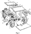
- FIG. 1 a machine of the system according to the invention, generically indicated by reference number 1.
- FIG. 1 it will be necessary for funicular traction plowing to provide two machines 1 according to the invention, working coupled each other.
- Machine 1 provides a frame 2, provided with four steering driving wheels 3, a driving and reversible control unit 4.
- a hoist 5 is mounted on said frame 2, said hoist 5 being provided with motor 6 and batteries 7, which, in the solution shown in the drawings, are supplied by energy provided by an electrode connected by an electric cable (not shown), and as auxiliary mode, by solar panels 8, mounted on the machinery.
- Hoist is provided with a safety clutch 16 preventing breaking cable 13.
- Each machine 1 provides stabilization electric jacks 9 (provided on the operation side of machine 1, i.e. toward inside the field to be worked on), and stabilization weights 10 (counterweights).
- a reclining working surface 11 is provided behind the machine 1.
- machine 1 provides a turret 12 for positioning equipments for the independent and remote automatic driving and/or communication equipments.
- the solution according to the invention provides an electronic unit (inside the driving unit, and thus not visible in the drawings) controlling the operation of machineries and managing driving, operative procedures by an autonomous and remote automatic driving, without the driver and based on algorithms also using Parallel Tracking system.
- Machine 1 can also be commuted from automatic driving in manual driving, useful for transferring the same from a field to another one.
- driving unit 4 is provided.
- Electronic unit provides a sophisticated positioning system, which comprises a satellite, radar and laser system, receiving all the information necessary for managing automatic driving under every condition, avoiding obstacles and ground roughness and managing alignment between machineries and advancement along the field.
- Electronic system further comprises a communication system between machines based on Wi-Fi and optional sensors provided on tools, Wireless Sensor Networks (WSN) aimed to ensure synchronism between the same and preventing working mistaken.
- WSN Wireless Sensor Networks
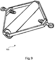
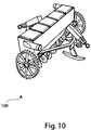
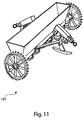
- figure 5 shows a harrow with spikes 101, figure 6 a harrow with discs 102, figure 7 a mower 103, figure 8 a subsoiler or ripper 104, figure 9 a roller 105, figure 10 a harvesting head 106, and figure 11 a manure machine 107.
- two machines 1 are placed on opposed sides of a field to be subjected to working (respectively one right-handed machine and one left-handed machine), each one provided with hoist 5, on which one or two metallic cables 13 wind, each cable having a length at least equal to the distance between the two machines. Free ends of cables 13 are fixed to opposite hooks of the working tool (e.g.
- active working position e.g. seeding and manure
- tool 102 will be, if necessary, inverted by an inversion mechanism setting the same for working according to the opposite direction, or it will be used in its bi-directional configuration, as for harrow 102.
- machines 1 according to the invention using the electronic positioning system, will move of an active length equivalent to the working width (e.g. plowing width) and actuation of hoists 5 will be inverted: driving (active) machinery 1 will put its hoist 5 in an idle mode (thus becoming passive) and the second one (passive) will actuate its hoist 5 (thus becoming active).
- active active machinery 1 will put its hoist 5 in an idle mode (thus becoming passive) and the second one (passive) will actuate its hoist 5 (thus becoming active).
- machines will advance along lateral headland of a distance equal to the working width.
- displacements are alternate, i.e. at the beginning of the every stroke, advancing only machine 1 with the tool moving away and with the hoist 5 idle.
- Electric supply of machines 1 is ensured by a surface electrode (fully or partially permanent or movable) (not shown) at the headings of the field to be subjected to working. Best exploitation of technology suggested is obtained also providing renewable energy sources (e.g. photovoltaic, aeolic or biomass energy), of the farm of close to the farm where the working is carried out.
- renewable energy sources e.g. photovoltaic, aeolic or biomass energy
- Machines 1 alternatively are driving machines, connecting the agricultural tool 100 (teeth harrow and/or disc harrow or morgano, seeder, ripper or subsoiler, roll, manure) to the two steel cables 13 operated by electric hoists 5, that can be of the vertical or horizontal axis drum type.
- Electric hoists 5 that can be of the vertical or horizontal axis drum type.
- Motors 14 of wheels 3, tool lifting slides 15, safety friction 16 and switching lights 17 are shown in the various figures.
- the machines 1 according to the invention can further comprise means for independent and remote automatic driving, comprised of hardware and software elements that, while driving means for ground working, must ensure a high safety level and at the same time permitting an easy programming of paths and a proper cover of the surface to be subjected to working.
- Means for independent and remote automatic driving must be able to:
- perimeter of ground to be subjected to working must be created by a limit that can be detected by laser scanners (reticulate, palisade, wall, hedge or even poles at a regular distance each other).
- GIS Global Information System
- Means for independent and remote automatic driving verify that position of limit detected by laser scanner, and geo-referenced by GPS, corresponds to instructions (and to the map) received from operator console. If anomalies are detected (lack of physical limit or no correspondence with the map), system enter in a safety mode, interrupting working and sending an alarm to the console.
- Means for independent and remote automatic driving on board of each machinery is comprised of:
- Each one of the two machineries is provided with a system comprising:
- Console is provided with:
- Processing unit is comprised of a "safety critical" application computer based on a calculation system with two processors connected by a 2002 architecture.
- two processors comprising the processing unit cany out the same functions, comparing intermediate results.
- one of the computers detects a discordance, it would put processing unit in a safety mode making a controlled transaction in a state involving stop for anomaly/failure of the whole system and sending an alarm to the console.
- Safe protocol ensures:
- driving system software sops the system.
- Each one of the two machines is provided with a GPS receiver used to define the working path on ground.
- Each one of the two means is provided of a bi-dimensional laser scanner which is used for:
- Two machines can be provided with a WSN module communicating with on board optional sensors of working tools and receives information suitable to modify and/or adapt working parameters to the climate and ground conditions.
- Two machines can be provided with camera, not for driving purposes, but that can be used to visualise ground from operator console.
- Console is based on a "Mobile PC” suitable to be used in an open environment (control computer) provided with graphic interface to define working program, i.e.: limiting machineries path (ground perimeter) and defining working path and modes.
- console can transmit working program to machineries, verifying position of machines carrying out diagnostic activities, interrupting or modifying working.
- GIS graphic interface permits limiting working limit on the map.
- the system permits defining limits as a trapezium.
- drive and working autonomous control system is programmed, defining geographic limits of ground to be subjected to working.
- Working lines are perpendicular to the advancement direction: traction machineries advance parallel with respect to the trapezium sides, and operator only has to indicate the working direction.
- geographic limit is always compared with physical limit detected by telemetric sensors (laser scanner).
- step a operator must verify that geographic perimeter delimitated during step a. Corresponds to physical delimitators provided on ground.
- Poles positioning operation cane be eased by a GPS connected with the same instrument employed to define geographic limit, thus evidencing the operator position on ground directly on interface.
- Traction machines will continuously compare physical limit and geographic limit, and every difference will be recorded: a too large difference will immediately cause a stop of working.
- a. and b. can be carried out only once, and they are valid for every king of working carried out on the same ground.
- Positioning of traction machines is obtained making the dark triangle (real position of the specific traction machine coinciding with clear triangle (set position of the traction machine start).
- traction machines "start set position" will be the position where activities have been suspended and specific traction machine must be positioned in the specific point.
- This phase can be started only when specific traction machine is positioned in the position set for start.
- Second traction machine is positioned at the distance provided for the type of working and the suitable tool is mounted on the machinery.
- steps 6) and 13) resistance conditions of ground are verified during traction and, if necessary, clutch is used.
Landscapes
- Life Sciences & Earth Sciences (AREA)
- Engineering & Computer Science (AREA)
- Mechanical Engineering (AREA)
- Soil Sciences (AREA)
- Environmental Sciences (AREA)
- Sustainable Energy (AREA)
- Sustainable Development (AREA)
- Power Engineering (AREA)
- Transportation (AREA)
- Agricultural Machines (AREA)
- Soil Working Implements (AREA)
- Guiding Agricultural Machines (AREA)
- Automatic Cycles, And Cycles In General (AREA)
Applications Claiming Priority (2)
| Application Number | Priority Date | Filing Date | Title |
|---|---|---|---|
| ITRM2009A000437A IT1395238B1 (it) | 2009-08-12 | 2009-08-12 | Sistema agricolo a trazione funicolare a propulsione elettrica. |
| PCT/IT2010/000353 WO2011018813A1 (en) | 2009-08-12 | 2010-08-04 | Agricultural funicular traction system with electric propulsion |
Publications (2)
| Publication Number | Publication Date |
|---|---|
| EP2464207A1 EP2464207A1 (en) | 2012-06-20 |
| EP2464207B1 true EP2464207B1 (en) | 2016-06-29 |
Family
ID=42035601
Family Applications (1)
| Application Number | Title | Priority Date | Filing Date |
|---|---|---|---|
| EP10763039.4A Not-in-force EP2464207B1 (en) | 2009-08-12 | 2010-08-04 | Agricultural funicular traction system with electric propulsion |
Country Status (9)
| Country | Link |
|---|---|
| US (1) | US8763714B2 (it) |
| EP (1) | EP2464207B1 (it) |
| CN (1) | CN102665384A (it) |
| BR (1) | BR112012003266A2 (it) |
| CA (1) | CA2770852A1 (it) |
| IN (1) | IN2012DN01283A (it) |
| IT (1) | IT1395238B1 (it) |
| RU (1) | RU2012108875A (it) |
| WO (1) | WO2011018813A1 (it) |
Families Citing this family (26)
| Publication number | Priority date | Publication date | Assignee | Title |
|---|---|---|---|---|
| EP2858471B1 (en) * | 2013-03-20 | 2016-06-01 | Couchman, Johnny | An autonomous farm vehicle |
| US9295192B2 (en) * | 2013-10-23 | 2016-03-29 | Elwha Llc | Agricultural access systems and methods |
| US9226443B2 (en) | 2013-10-23 | 2016-01-05 | Elwha Llc | Agricultural access systems and methods |
| JP6368964B2 (ja) * | 2014-03-26 | 2018-08-08 | ヤンマー株式会社 | 作業車両の制御装置 |
| US10095241B2 (en) * | 2014-06-30 | 2018-10-09 | Yanmar Co., Ltd. | Parallel travel work system |
| CN204539725U (zh) * | 2015-04-22 | 2015-08-12 | 河北农业大学 | 一种设施农业激光测控电动旋平机 |
| UA125335C2 (uk) | 2015-05-19 | 2022-02-23 | Зе Клаймет Корпорейшн | Захисний з'єднувач та його застосування |
| BR102016006251B1 (pt) * | 2016-03-22 | 2018-06-19 | Eirene Projetos E Consultoria Ltda | Veículo terrestre não tripulado para agricultura e processo de pulverização utilizando veículo terrestre não tripulado para agricultura |
| CN105900543A (zh) * | 2016-04-08 | 2016-08-31 | 安徽宝昱电子科技有限公司 | 一种可调节圆盘耙深度的连接器 |
| CN105960869B (zh) * | 2016-06-23 | 2018-06-12 | 刘华安 | 电动牵引式农田耕作方法和系统 |
| CN105993220A (zh) * | 2016-06-27 | 2016-10-12 | 蔡红梅 | 一种农业上用于播种后镇压的小麦镇压器 |
| CN106211833B (zh) * | 2016-07-26 | 2018-07-20 | 吉林省农业科学院 | 一种田间农机驱动装置 |
| CN106358531B (zh) * | 2016-08-25 | 2018-08-14 | 吉林省农业科学院 | 一种农用绞盘结构 |
| HRPK20170314B3 (hr) * | 2017-02-24 | 2018-12-14 | Gordan Palić | Sustav za obradu zemlje |
| CN107255976A (zh) * | 2017-07-24 | 2017-10-17 | 欧思星通科技(北京)有限公司 | 基于“互联网+北斗+gis”服务的智慧农场监管系统 |
| AR114634A1 (es) * | 2018-02-21 | 2020-09-30 | Syngenta Crop Protection Ag | Método y dispositivo de siembra de precisión |
| DE102018212150A1 (de) * | 2018-07-20 | 2020-01-23 | Deere & Company | Verfahren zur Energieversorgung eines kabelgebundenen betriebenen Feldhäckslers |
| NL2022048B1 (en) * | 2018-11-22 | 2020-06-05 | Agxeed B V | Autonomous tractor and method to cultivate farmland using this tractor |
| US12016257B2 (en) * | 2020-02-19 | 2024-06-25 | Sabanto, Inc. | Methods for detecting and clearing debris from planter gauge wheels, closing wheels and seed tubes |
| CN111448865B (zh) * | 2020-04-13 | 2024-12-31 | 中国热带农业科学院南亚热带作物研究所 | 一种用于农用机具的智能牵引与移动装置 |
| CN112534976B (zh) * | 2020-12-07 | 2022-02-15 | 四川美术学院 | 一种山地犁田机 |
| CN113079715B (zh) * | 2021-03-30 | 2022-02-15 | 鄂尔多斯市云东生态产业开发有限公司 | 一种园林苗圃用松土装置 |
| CN113152550B (zh) * | 2021-04-07 | 2022-12-20 | 柳州柳工挖掘机有限公司 | 操作模式控制系统及方法和挖掘机 |
| CN113110621B (zh) * | 2021-05-24 | 2024-08-27 | 无锡宏霸机电股份有限公司 | 基于多电机联动模式光伏系统及光伏跟踪控制方法 |
| JP7342914B2 (ja) * | 2021-06-29 | 2023-09-12 | 井関農機株式会社 | 作業車両 |
| JP7344453B2 (ja) * | 2021-11-15 | 2023-09-14 | 井関農機株式会社 | 作業車両 |
Family Cites Families (28)
| Publication number | Priority date | Publication date | Assignee | Title |
|---|---|---|---|---|
| US509556A (en) * | 1893-11-28 | Electric plow | ||
| GB117856A (en) * | 1917-08-15 | 1918-08-08 | Francis Giveran Parry | Improvements in Plough or like Cultivating Implements. |
| FR24334E (fr) * | 1919-03-21 | 1922-06-20 | Societe John Fowler & Company Leeds Limited | Machines de labour et de culture à traction mécanique |
| US1367127A (en) * | 1919-07-17 | 1921-02-01 | Charles B Culbertson | Reversible plow |
| US1503467A (en) * | 1923-05-25 | 1924-08-05 | Bertella Armando | Cable-operated plow |
| US1670734A (en) * | 1924-10-01 | 1928-05-22 | Manning Maxwell & Moore Inc | Electric hoist |
| US1733242A (en) * | 1927-02-14 | 1929-10-29 | Semenza Marco | System of electric plowing by direct traction |
| US1717209A (en) * | 1927-03-14 | 1929-06-11 | Hester Levi Cummings | Power lift for tractor plows |
| US1908556A (en) * | 1929-01-31 | 1933-05-09 | Rigondeau Louis Gaston | Motor driven winch |
| FR52671E (fr) * | 1942-06-15 | 1945-05-16 | Cie Lyonnaise Des Ascenseurs R | Perfectionnements aux systèmes d'entraînement à traction par câble pour engins ou outils de culture |
| US3186493A (en) * | 1959-05-06 | 1965-06-01 | Leonard D Barry | Automatic farming system |
| US3601200A (en) * | 1969-03-13 | 1971-08-24 | Russell C Bauman | Automatic apparatus |
| SU938760A1 (ru) * | 1980-01-02 | 1982-06-30 | Nazarov Erkin M | Почвообрабатывающий агрегат |
| US4369590A (en) * | 1980-12-03 | 1983-01-25 | Miller Michael E | Rear mounted scraper for vehicles |
| US5189867A (en) * | 1988-04-13 | 1993-03-02 | Michael Schmidt | Aquatic vegetation cutter |
| DE3909984A1 (de) * | 1989-03-25 | 1990-09-27 | Helmut Dipl Ing Bauer | Geraetetraegersystem fuer ein-mann-arbeit im steillagenweinbau |
| RO107069B1 (ro) * | 1990-08-17 | 1993-09-30 | Negut Lucian New York Ro Carag | Procedeu și dispozitiv de eliminare a patinării tractoarelor |
| US5074105A (en) * | 1991-01-22 | 1991-12-24 | Roth George L | Lake rake and methods |
| BE1007083A5 (nl) * | 1993-05-26 | 1995-03-07 | Leijenaar Sytze | Inrichting voor het behandelen van gewas. |
| FI942218A0 (fi) * | 1994-05-13 | 1994-05-13 | Modulaire Oy | Automatiskt styrningssystem foer obemannat fordon |
| US5511366A (en) * | 1995-02-22 | 1996-04-30 | Roth; George L. | Water body cleaning apparatus and method |
| DE19647523A1 (de) * | 1996-11-16 | 1998-05-20 | Claas Ohg | Landwirtschaftliches Nutzfahrzeug mit einem in seiner Lage und/oder Ausrichtung gegenüber dem Fahrzeug verstellbar angeordneten Bearbeitungsgerät |
| US6449931B1 (en) * | 2000-02-02 | 2002-09-17 | The Master's Dredging Company, Inc. | Aquatic vegetation shredder having bow and stern mounted high speed, large chopping propellers |
| US6393812B1 (en) * | 2000-10-31 | 2002-05-28 | Hydromentia, Inc. | Method and apparatus for gathering, transporting, and processing aquatic plants |
| US7032763B1 (en) * | 2002-11-18 | 2006-04-25 | Mi-Jack Products, Inc. | System and method for automatically guiding a gantry crane |
| US7344037B1 (en) * | 2002-11-18 | 2008-03-18 | Mi-Jack Products, Inc. | Inventory storage and retrieval system and method with guidance for load-handling vehicle |
| GB2398394B (en) * | 2003-02-14 | 2006-05-17 | Dyson Ltd | An autonomous machine |
| US7305811B2 (en) * | 2005-12-09 | 2007-12-11 | Eugene Murawski | Side mower deck for a mower tractor |
-
2009
- 2009-08-12 IT ITRM2009A000437A patent/IT1395238B1/it active
-
2010
- 2010-08-04 IN IN1283DEN2012 patent/IN2012DN01283A/en unknown
- 2010-08-04 EP EP10763039.4A patent/EP2464207B1/en not_active Not-in-force
- 2010-08-04 CN CN2010800360670A patent/CN102665384A/zh active Pending
- 2010-08-04 RU RU2012108875/13A patent/RU2012108875A/ru not_active Application Discontinuation
- 2010-08-04 US US13/390,071 patent/US8763714B2/en not_active Expired - Fee Related
- 2010-08-04 CA CA2770852A patent/CA2770852A1/en not_active Abandoned
- 2010-08-04 WO PCT/IT2010/000353 patent/WO2011018813A1/en not_active Ceased
- 2010-08-04 BR BR112012003266A patent/BR112012003266A2/pt not_active IP Right Cessation
Also Published As
| Publication number | Publication date |
|---|---|
| WO2011018813A1 (en) | 2011-02-17 |
| IN2012DN01283A (it) | 2015-05-15 |
| BR112012003266A2 (pt) | 2016-03-01 |
| US8763714B2 (en) | 2014-07-01 |
| EP2464207A1 (en) | 2012-06-20 |
| IT1395238B1 (it) | 2012-09-05 |
| US20120186213A1 (en) | 2012-07-26 |
| CN102665384A (zh) | 2012-09-12 |
| ITRM20090437A1 (it) | 2011-02-13 |
| RU2012108875A (ru) | 2013-09-20 |
| CA2770852A1 (en) | 2011-02-17 |
Similar Documents
| Publication | Publication Date | Title |
|---|---|---|
| EP2464207B1 (en) | Agricultural funicular traction system with electric propulsion | |
| KR102001517B1 (ko) | 농업생산 무인자동화를 위한 주행 로봇 | |
| US8234010B2 (en) | Tethered robot positioning | |
| EP2596693B1 (en) | Autonomous self-actuated ploughing implement | |
| US20170227969A1 (en) | Autonomous robotic agricultural machine and system thereof | |
| EP4084986B1 (en) | Electric powered self-propelled driving machine | |
| JP6426219B2 (ja) | 草踏み機 | |
| JP2017131199A (ja) | 植林システム、植林方法、耕作機械、植付機械及び管理装置 | |
| JP2020113121A (ja) | 営農システム | |
| KR102389383B1 (ko) | 무한궤도형 주행부를 포함하는 제초 로봇 | |
| KR20200057961A (ko) | 원격조정이 가능한 무인 작업장치 | |
| CN205681805U (zh) | 电动牵引式农田耕作系统 | |
| JP7301737B2 (ja) | 作業車両 | |
| JP6897744B2 (ja) | 作業車連携システム | |
| EP4473820A1 (en) | Underwater planting machine, underwater planting system, and underwater planting method | |
| JP3294467B2 (ja) | 移植機の駆動装置 | |
| KR102543649B1 (ko) | 태양광 구조물 및 농기계를 이용한 영농 자동화 시스템 | |
| JP2021045091A (ja) | 誘引装置 | |
| CN104335996A (zh) | 一种遥控自走式植保喷药机 | |
| JPH06175722A (ja) | 農作業機の圃場作業制御システム | |
| JP2022010873A (ja) | 作業車両の制御システム | |
| JP2022010872A (ja) | 作業車両の制御システム | |
| CN105960869B (zh) | 电动牵引式农田耕作方法和系统 | |
| JP7012370B2 (ja) | 管理機及び圃場管理方法 | |
| CN205883899U (zh) | 一种水田机械牵引装置以及水田机械 |
Legal Events
| Date | Code | Title | Description |
|---|---|---|---|
| PUAI | Public reference made under article 153(3) epc to a published international application that has entered the european phase |
Free format text: ORIGINAL CODE: 0009012 |
|
| 17P | Request for examination filed |
Effective date: 20120210 |
|
| AK | Designated contracting states |
Kind code of ref document: A1 Designated state(s): AL AT BE BG CH CY CZ DE DK EE ES FI FR GB GR HR HU IE IS IT LI LT LU LV MC MK MT NL NO PL PT RO SE SI SK SM TR |
|
| AX | Request for extension of the european patent |
Extension state: BA RS |
|
| RAX | Requested extension states of the european patent have changed |
Extension state: BA Payment date: 20120210 Extension state: RS Payment date: 20120210 |
|
| REG | Reference to a national code |
Ref country code: DE Ref legal event code: R079 Ref document number: 602010034332 Country of ref document: DE Free format text: PREVIOUS MAIN CLASS: A01B0003640000 Ipc: A01B0069040000 |
|
| GRAP | Despatch of communication of intention to grant a patent |
Free format text: ORIGINAL CODE: EPIDOSNIGR1 |
|
| RIC1 | Information provided on ipc code assigned before grant |
Ipc: A01B 3/64 20060101ALI20150910BHEP Ipc: A01B 69/04 20060101AFI20150910BHEP |
|
| DAX | Request for extension of the european patent (deleted) | ||
| INTG | Intention to grant announced |
Effective date: 20150930 |
|
| GRAS | Grant fee paid |
Free format text: ORIGINAL CODE: EPIDOSNIGR3 |
|
| RAP1 | Party data changed (applicant data changed or rights of an application transferred) |
Owner name: ZOFFOLI, ANDREA |
|
| RIN1 | Information on inventor provided before grant (corrected) |
Inventor name: ZOFFOLI, ANDREA |
|
| GRAA | (expected) grant |
Free format text: ORIGINAL CODE: 0009210 |
|
| AK | Designated contracting states |
Kind code of ref document: B1 Designated state(s): AL AT BE BG CH CY CZ DE DK EE ES FI FR GB GR HR HU IE IS IT LI LT LU LV MC MK MT NL NO PL PT RO SE SI SK SM TR |
|
| REG | Reference to a national code |
Ref country code: GB Ref legal event code: FG4D |
|
| REG | Reference to a national code |
Ref country code: CH Ref legal event code: EP |
|
| REG | Reference to a national code |
Ref country code: AT Ref legal event code: REF Ref document number: 808328 Country of ref document: AT Kind code of ref document: T Effective date: 20160715 |
|
| REG | Reference to a national code |
Ref country code: IE Ref legal event code: FG4D |
|
| REG | Reference to a national code |
Ref country code: DE Ref legal event code: R096 Ref document number: 602010034332 Country of ref document: DE |
|
| REG | Reference to a national code |
Ref country code: FR Ref legal event code: PLFP Year of fee payment: 7 |
|
| REG | Reference to a national code |
Ref country code: LT Ref legal event code: MG4D |
|
| PG25 | Lapsed in a contracting state [announced via postgrant information from national office to epo] |
Ref country code: FI Free format text: LAPSE BECAUSE OF FAILURE TO SUBMIT A TRANSLATION OF THE DESCRIPTION OR TO PAY THE FEE WITHIN THE PRESCRIBED TIME-LIMIT Effective date: 20160629 Ref country code: LT Free format text: LAPSE BECAUSE OF FAILURE TO SUBMIT A TRANSLATION OF THE DESCRIPTION OR TO PAY THE FEE WITHIN THE PRESCRIBED TIME-LIMIT Effective date: 20160629 Ref country code: NO Free format text: LAPSE BECAUSE OF FAILURE TO SUBMIT A TRANSLATION OF THE DESCRIPTION OR TO PAY THE FEE WITHIN THE PRESCRIBED TIME-LIMIT Effective date: 20160929 |
|
| REG | Reference to a national code |
Ref country code: NL Ref legal event code: MP Effective date: 20160629 |
|
| PG25 | Lapsed in a contracting state [announced via postgrant information from national office to epo] |
Ref country code: NL Free format text: LAPSE BECAUSE OF FAILURE TO SUBMIT A TRANSLATION OF THE DESCRIPTION OR TO PAY THE FEE WITHIN THE PRESCRIBED TIME-LIMIT Effective date: 20160629 Ref country code: SE Free format text: LAPSE BECAUSE OF FAILURE TO SUBMIT A TRANSLATION OF THE DESCRIPTION OR TO PAY THE FEE WITHIN THE PRESCRIBED TIME-LIMIT Effective date: 20160629 Ref country code: GR Free format text: LAPSE BECAUSE OF FAILURE TO SUBMIT A TRANSLATION OF THE DESCRIPTION OR TO PAY THE FEE WITHIN THE PRESCRIBED TIME-LIMIT Effective date: 20160930 Ref country code: HR Free format text: LAPSE BECAUSE OF FAILURE TO SUBMIT A TRANSLATION OF THE DESCRIPTION OR TO PAY THE FEE WITHIN THE PRESCRIBED TIME-LIMIT Effective date: 20160629 Ref country code: LV Free format text: LAPSE BECAUSE OF FAILURE TO SUBMIT A TRANSLATION OF THE DESCRIPTION OR TO PAY THE FEE WITHIN THE PRESCRIBED TIME-LIMIT Effective date: 20160629 |
|
| REG | Reference to a national code |
Ref country code: AT Ref legal event code: MK05 Ref document number: 808328 Country of ref document: AT Kind code of ref document: T Effective date: 20160629 |
|
| PG25 | Lapsed in a contracting state [announced via postgrant information from national office to epo] |
Ref country code: BE Free format text: LAPSE BECAUSE OF NON-PAYMENT OF DUE FEES Effective date: 20160831 |
|
| PG25 | Lapsed in a contracting state [announced via postgrant information from national office to epo] |
Ref country code: IT Free format text: LAPSE BECAUSE OF FAILURE TO SUBMIT A TRANSLATION OF THE DESCRIPTION OR TO PAY THE FEE WITHIN THE PRESCRIBED TIME-LIMIT Effective date: 20160629 Ref country code: RO Free format text: LAPSE BECAUSE OF FAILURE TO SUBMIT A TRANSLATION OF THE DESCRIPTION OR TO PAY THE FEE WITHIN THE PRESCRIBED TIME-LIMIT Effective date: 20160629 Ref country code: EE Free format text: LAPSE BECAUSE OF FAILURE TO SUBMIT A TRANSLATION OF THE DESCRIPTION OR TO PAY THE FEE WITHIN THE PRESCRIBED TIME-LIMIT Effective date: 20160629 Ref country code: CZ Free format text: LAPSE BECAUSE OF FAILURE TO SUBMIT A TRANSLATION OF THE DESCRIPTION OR TO PAY THE FEE WITHIN THE PRESCRIBED TIME-LIMIT Effective date: 20160629 Ref country code: SK Free format text: LAPSE BECAUSE OF FAILURE TO SUBMIT A TRANSLATION OF THE DESCRIPTION OR TO PAY THE FEE WITHIN THE PRESCRIBED TIME-LIMIT Effective date: 20160629 Ref country code: IS Free format text: LAPSE BECAUSE OF FAILURE TO SUBMIT A TRANSLATION OF THE DESCRIPTION OR TO PAY THE FEE WITHIN THE PRESCRIBED TIME-LIMIT Effective date: 20161029 |
|
| PG25 | Lapsed in a contracting state [announced via postgrant information from national office to epo] |
Ref country code: BE Free format text: LAPSE BECAUSE OF FAILURE TO SUBMIT A TRANSLATION OF THE DESCRIPTION OR TO PAY THE FEE WITHIN THE PRESCRIBED TIME-LIMIT Effective date: 20160629 Ref country code: PT Free format text: LAPSE BECAUSE OF FAILURE TO SUBMIT A TRANSLATION OF THE DESCRIPTION OR TO PAY THE FEE WITHIN THE PRESCRIBED TIME-LIMIT Effective date: 20161031 Ref country code: ES Free format text: LAPSE BECAUSE OF FAILURE TO SUBMIT A TRANSLATION OF THE DESCRIPTION OR TO PAY THE FEE WITHIN THE PRESCRIBED TIME-LIMIT Effective date: 20160629 Ref country code: SM Free format text: LAPSE BECAUSE OF FAILURE TO SUBMIT A TRANSLATION OF THE DESCRIPTION OR TO PAY THE FEE WITHIN THE PRESCRIBED TIME-LIMIT Effective date: 20160629 Ref country code: PL Free format text: LAPSE BECAUSE OF FAILURE TO SUBMIT A TRANSLATION OF THE DESCRIPTION OR TO PAY THE FEE WITHIN THE PRESCRIBED TIME-LIMIT Effective date: 20160629 Ref country code: AT Free format text: LAPSE BECAUSE OF FAILURE TO SUBMIT A TRANSLATION OF THE DESCRIPTION OR TO PAY THE FEE WITHIN THE PRESCRIBED TIME-LIMIT Effective date: 20160629 |
|
| REG | Reference to a national code |
Ref country code: DE Ref legal event code: R097 Ref document number: 602010034332 Country of ref document: DE |
|
| PG25 | Lapsed in a contracting state [announced via postgrant information from national office to epo] |
Ref country code: MC Free format text: LAPSE BECAUSE OF FAILURE TO SUBMIT A TRANSLATION OF THE DESCRIPTION OR TO PAY THE FEE WITHIN THE PRESCRIBED TIME-LIMIT Effective date: 20160629 |
|
| REG | Reference to a national code |
Ref country code: CH Ref legal event code: PL |
|
| PG25 | Lapsed in a contracting state [announced via postgrant information from national office to epo] |
Ref country code: CH Free format text: LAPSE BECAUSE OF NON-PAYMENT OF DUE FEES Effective date: 20160831 Ref country code: LI Free format text: LAPSE BECAUSE OF NON-PAYMENT OF DUE FEES Effective date: 20160831 |
|
| PLBE | No opposition filed within time limit |
Free format text: ORIGINAL CODE: 0009261 |
|
| STAA | Information on the status of an ep patent application or granted ep patent |
Free format text: STATUS: NO OPPOSITION FILED WITHIN TIME LIMIT |
|
| PG25 | Lapsed in a contracting state [announced via postgrant information from national office to epo] |
Ref country code: DK Free format text: LAPSE BECAUSE OF FAILURE TO SUBMIT A TRANSLATION OF THE DESCRIPTION OR TO PAY THE FEE WITHIN THE PRESCRIBED TIME-LIMIT Effective date: 20160629 |
|
| REG | Reference to a national code |
Ref country code: IE Ref legal event code: MM4A |
|
| 26N | No opposition filed |
Effective date: 20170330 |
|
| PG25 | Lapsed in a contracting state [announced via postgrant information from national office to epo] |
Ref country code: IE Free format text: LAPSE BECAUSE OF NON-PAYMENT OF DUE FEES Effective date: 20160804 |
|
| REG | Reference to a national code |
Ref country code: FR Ref legal event code: PLFP Year of fee payment: 8 |
|
| PG25 | Lapsed in a contracting state [announced via postgrant information from national office to epo] |
Ref country code: LU Free format text: LAPSE BECAUSE OF NON-PAYMENT OF DUE FEES Effective date: 20160804 Ref country code: BG Free format text: LAPSE BECAUSE OF FAILURE TO SUBMIT A TRANSLATION OF THE DESCRIPTION OR TO PAY THE FEE WITHIN THE PRESCRIBED TIME-LIMIT Effective date: 20160929 Ref country code: SI Free format text: LAPSE BECAUSE OF FAILURE TO SUBMIT A TRANSLATION OF THE DESCRIPTION OR TO PAY THE FEE WITHIN THE PRESCRIBED TIME-LIMIT Effective date: 20160629 |
|
| PG25 | Lapsed in a contracting state [announced via postgrant information from national office to epo] |
Ref country code: HU Free format text: LAPSE BECAUSE OF FAILURE TO SUBMIT A TRANSLATION OF THE DESCRIPTION OR TO PAY THE FEE WITHIN THE PRESCRIBED TIME-LIMIT; INVALID AB INITIO Effective date: 20100804 Ref country code: CY Free format text: LAPSE BECAUSE OF FAILURE TO SUBMIT A TRANSLATION OF THE DESCRIPTION OR TO PAY THE FEE WITHIN THE PRESCRIBED TIME-LIMIT Effective date: 20160629 |
|
| REG | Reference to a national code |
Ref country code: FR Ref legal event code: PLFP Year of fee payment: 9 |
|
| PG25 | Lapsed in a contracting state [announced via postgrant information from national office to epo] |
Ref country code: MT Free format text: LAPSE BECAUSE OF NON-PAYMENT OF DUE FEES Effective date: 20160831 Ref country code: MK Free format text: LAPSE BECAUSE OF FAILURE TO SUBMIT A TRANSLATION OF THE DESCRIPTION OR TO PAY THE FEE WITHIN THE PRESCRIBED TIME-LIMIT Effective date: 20160629 Ref country code: TR Free format text: LAPSE BECAUSE OF FAILURE TO SUBMIT A TRANSLATION OF THE DESCRIPTION OR TO PAY THE FEE WITHIN THE PRESCRIBED TIME-LIMIT Effective date: 20160629 |
|
| PG25 | Lapsed in a contracting state [announced via postgrant information from national office to epo] |
Ref country code: AL Free format text: LAPSE BECAUSE OF FAILURE TO SUBMIT A TRANSLATION OF THE DESCRIPTION OR TO PAY THE FEE WITHIN THE PRESCRIBED TIME-LIMIT Effective date: 20160629 |
|
| PGFP | Annual fee paid to national office [announced via postgrant information from national office to epo] |
Ref country code: FR Payment date: 20210611 Year of fee payment: 12 |
|
| PGFP | Annual fee paid to national office [announced via postgrant information from national office to epo] |
Ref country code: DE Payment date: 20210630 Year of fee payment: 12 Ref country code: GB Payment date: 20210701 Year of fee payment: 12 |
|
| REG | Reference to a national code |
Ref country code: DE Ref legal event code: R119 Ref document number: 602010034332 Country of ref document: DE |
|
| GBPC | Gb: european patent ceased through non-payment of renewal fee |
Effective date: 20220804 |
|
| PG25 | Lapsed in a contracting state [announced via postgrant information from national office to epo] |
Ref country code: FR Free format text: LAPSE BECAUSE OF NON-PAYMENT OF DUE FEES Effective date: 20220831 Ref country code: DE Free format text: LAPSE BECAUSE OF NON-PAYMENT OF DUE FEES Effective date: 20230301 |
|
| PG25 | Lapsed in a contracting state [announced via postgrant information from national office to epo] |
Ref country code: GB Free format text: LAPSE BECAUSE OF NON-PAYMENT OF DUE FEES Effective date: 20220804 |