EP2463986A1 - Tragbares elektronisches Gerät - Google Patents
Tragbares elektronisches Gerät Download PDFInfo
- Publication number
- EP2463986A1 EP2463986A1 EP10290647A EP10290647A EP2463986A1 EP 2463986 A1 EP2463986 A1 EP 2463986A1 EP 10290647 A EP10290647 A EP 10290647A EP 10290647 A EP10290647 A EP 10290647A EP 2463986 A1 EP2463986 A1 EP 2463986A1
- Authority
- EP
- European Patent Office
- Prior art keywords
- spring
- energy
- portable electronic
- primary
- accumulator
- Prior art date
- Legal status (The legal status is an assumption and is not a legal conclusion. Google has not performed a legal analysis and makes no representation as to the accuracy of the status listed.)
- Withdrawn
Links
Images


Classifications
-
- H—ELECTRICITY
- H02—GENERATION; CONVERSION OR DISTRIBUTION OF ELECTRIC POWER
- H02K—DYNAMO-ELECTRIC MACHINES
- H02K7/00—Arrangements for handling mechanical energy structurally associated with dynamo-electric machines, e.g. structural association with mechanical driving motors or auxiliary dynamo-electric machines
- H02K7/18—Structural association of electric generators with mechanical driving motors, e.g. with turbines
- H02K7/1807—Rotary generators
- H02K7/1853—Rotary generators driven by intermittent forces
-
- G—PHYSICS
- G04—HOROLOGY
- G04C—ELECTROMECHANICAL CLOCKS OR WATCHES
- G04C10/00—Arrangements of electric power supplies in time pieces
-
- H—ELECTRICITY
- H04—ELECTRIC COMMUNICATION TECHNIQUE
- H04M—TELEPHONIC COMMUNICATION
- H04M1/00—Substation equipment, e.g. for use by subscribers
- H04M1/02—Constructional features of telephone sets
- H04M1/0202—Portable telephone sets, e.g. cordless phones, mobile phones or bar type handsets
- H04M1/0206—Portable telephones comprising a plurality of mechanically joined movable body parts, e.g. hinged housings
- H04M1/0208—Portable telephones comprising a plurality of mechanically joined movable body parts, e.g. hinged housings characterized by the relative motions of the body parts
- H04M1/0214—Foldable telephones, i.e. with body parts pivoting to an open position around an axis parallel to the plane they define in closed position
-
- H—ELECTRICITY
- H02—GENERATION; CONVERSION OR DISTRIBUTION OF ELECTRIC POWER
- H02J—CIRCUIT ARRANGEMENTS OR SYSTEMS FOR SUPPLYING OR DISTRIBUTING ELECTRIC POWER; SYSTEMS FOR STORING ELECTRIC ENERGY
- H02J7/00—Circuit arrangements for charging or depolarising batteries or for supplying loads from batteries
- H02J7/32—Circuit arrangements for charging or depolarising batteries or for supplying loads from batteries for charging batteries from a charging set comprising a non-electric prime mover rotating at constant speed
-
- H—ELECTRICITY
- H02—GENERATION; CONVERSION OR DISTRIBUTION OF ELECTRIC POWER
- H02K—DYNAMO-ELECTRIC MACHINES
- H02K7/00—Arrangements for handling mechanical energy structurally associated with dynamo-electric machines, e.g. structural association with mechanical driving motors or auxiliary dynamo-electric machines
- H02K7/18—Structural association of electric generators with mechanical driving motors, e.g. with turbines
- H02K7/1807—Rotary generators
- H02K7/1861—Rotary generators driven by animals or vehicles
-
- Y—GENERAL TAGGING OF NEW TECHNOLOGICAL DEVELOPMENTS; GENERAL TAGGING OF CROSS-SECTIONAL TECHNOLOGIES SPANNING OVER SEVERAL SECTIONS OF THE IPC; TECHNICAL SUBJECTS COVERED BY FORMER USPC CROSS-REFERENCE ART COLLECTIONS [XRACs] AND DIGESTS
- Y02—TECHNOLOGIES OR APPLICATIONS FOR MITIGATION OR ADAPTATION AGAINST CLIMATE CHANGE
- Y02B—CLIMATE CHANGE MITIGATION TECHNOLOGIES RELATED TO BUILDINGS, e.g. HOUSING, HOUSE APPLIANCES OR RELATED END-USER APPLICATIONS
- Y02B40/00—Technologies aiming at improving the efficiency of home appliances, e.g. induction cooking or efficient technologies for refrigerators, freezers or dish washers
Definitions
- the present invention relates to a portable electronic device, in particular a mobile phone, comprising a source of energy, such as an accumulator, a battery, a capacitor, etc., manually rechargeable.
- a source of energy such as an accumulator, a battery, a capacitor, etc.
- the power source of a portable electronic device is normally electrically rechargeable, i.e. by connecting the device to the mains via a transformer.
- portable electronic devices whose source of energy can be recharged manually.
- These devices comprise a manual actuating device, such as a crank, a wheel, a lever or a pusher protruding from an outer face of the apparatus and allowing the user to rotate the rotor of the apparatus.
- an electric generator electrically connected to the power source.
- a disadvantage of these devices is that they require a specific manual actuator, accessible from the outside of the device, and which can therefore affect the aesthetics of the device.
- Another disadvantage is that they require a specific action by the user to recharge the power source.
- the advantage of this device is that it uses the kinetic energy generated by manual actions of normal use of the device, namely its opening and closing, to produce electricity and recharge the power source . No Specific actuator accessible to the user is necessary, so that the apparatus can have a normal appearance.
- this device has the disadvantage of having a low rate of return in terms of charging the power source.
- the electric generator is operated only during the relative movements of the two articulated parts.
- the charging efficiency of a power source depends more on the charging time than on the intensity of the current produced by the electric generator, the charging current being in any case clipped to a constant value.
- the present invention aims to provide a portable electronic device with manual recharging device of the energy source, which allows to increase the performance of the recharge.
- said means are adapted to repeat the succession of steps a) and b) until the first spring energy accumulator is substantially completely discharged.
- the force of the second spring energy accumulator i.e., the stiffness of said spring, is less than the force of the first spring energy accumulator.
- said mechanism further comprises a third spring energy accumulator arranged to partially receive the energy released from the second spring energy accumulator, and said means are adapted to release stored energy. in this third spring energy accumulator and supply it, at least in part, to said second of the electric generators.
- the force of the third spring energy accumulator is less than the force of the second spring energy accumulator.
- Said means typically comprise clutch means for selectively blocking or releasing the spring energy accumulators.
- the spring energy accumulators may each comprise a drum housing a spiral energy storage spring.
- the first and second moving parts each comprise elements participating in the normal operation of the apparatus, and said mechanism, with the electrical generator or generators, and the energy source are each located in one of said first and second parts. mobile.
- the first and second movable parts can be hinged to each other by a hinge.
- a portable electronic device is in the form of a mobile phone 1 as shown in FIGS. Figures 1 to 3 .
- the telephone 1 is in two parts 2, 3 pivoting relative to each other via a hinge 4. Each of these two parts 2, 3 comprises elements involved in the normal operation of the phone.
- the first part 2, called “base” in the suite includes a keyboard on its face inside 5, a microphone on its inner face 5, on its end flank 6 or inside its shell 7 and an electronic card inside its shell 7.
- the electronic card includes the processor 8 of the telephone , a rechargeable battery 9 supplying the telephone with electrical power and a battery charge management circuit 9.
- the second part 3 typically comprises a screen and an earphone on its inner face 11 and corresponding electronic circuits inside its shell 12, these electronic circuits communicating with the electronic circuits of the base 2 through the hinge 4.
- the base 2 and the valve 3 are spaced angularly from one another, making accessible the keyboard and the screen.
- the flap 3 is folded against the base 2 and the screen and the keyboard are not accessible.
- the battery 9 can be recharged by connecting the telephone to the mains via a transformer 13.
- the load management circuit 10 interconnected between the transformer 13 and the battery 9 detects the presence of the transformer 13, provides the battery 9 the electrical energy from the sector and indicates to the processor 8 the level of charge of the battery 9.
- the telephone is also manually rechargeable by means of a mechanism which will now be described.
- the hinge 4 is defined by a central portion 14 integral with the base 2 and the lateral portions 15 integral with the valve 3.
- a toothed wheel 16 is mounted in the central portion 14 coaxially with the hinge 4.
- This toothed wheel 16 cooperates with a mechanism 17 mounted in the valve 3 and comprising a gear train 18, a clutch 19, primary and secondary spring energy accumulators 20, 21 and an electric generator 22.
- the mechanism 17 is visible through a transparent portion of the shell 12 of the valve 3.
- the figure 4 shows in detail the hinge wheel 16 and a part of the gear train 18.
- the hinge wheel 16 is mounted free to rotate about an axis 23 integral with the base 2.
- the axis 23 is constituted by a non-threaded portion of the rod of a screw 24 whose threaded portion is screwed into the central portion 14 of the hinge 4.
- the hinge wheel 16 is coaxial and integral with a plate 25 carrying pawls 26 which cooperate with an asymmetric toothed wheel 27 mounted integral around the axis 23. When the phone is opened, the pawls 26 prevent the hinge wheel 16 from rotating, thus making it integral with the base 2.
- the train of gear 18 mounted in the valve 3 and cooperating with the toothing of the hinge wheel 16 is then rotated to reassemble the mechanism 17, specifically the primary spring energy accumulator 20.
- the gear train 18 is blocked, as this will be explained below, but the pawls 26 allow rotation of the hinge wheel 16 to allow the hinge 4 to operate.
- the gear train 18 comprises a series of pinions located in the plane of the hinge wheel 16, the last of these gears, 28, being coaxial and integral with a first bevel gear 29, and a pinion 30 located in a plane parallel to the plane of the valve 3, this pinion 30 being coaxial and integral with a second bevel gear 31 which meshes with the first bevel gear 29.
- the pinion 30 meshes with a pinion 32 which itself meshes with a primary winding wheel 33 mounted integral around a primary cylinder shaft 34.
- a pawl 35 cooperates with the toothing of the primary winding wheel 33 to allow its rotation in one direction, corresponding to the opening of the telephone, and prevent rotation in the other direction, corresponding to the closing of the phone.
- a primary barrel drum 36 is rotatably mounted around the primary barrel shaft 34.
- the primary barrel drum 36 houses a spiral-shaped primary energy-storage spring 37 and has an external toothing 38.
- spring primary end 37 has its inner end fixed to the primary barrel shaft 34 and its outer end connected to the inner wall of the primary barrel drum 36 via a sliding flange, as is known in the watch industry.
- the assembly 33, 34, 36, 37 forms the primary spring energy accumulator 20.
- the primary drum drum 36 can be closed by a cover 36a, as shown in FIG. figure 6 .
- the clutch 19 is of the vertical clutch type, also called axial clutch, and also comprises a lower wheel 40 coaxial with the wheel 39.
- the clutch 19 can assume an engaged position in which the upper and lower wheels 39, 40 can rotate integrally with one another and a disengaged position where the upper wheel 39 is immobilized and the lower wheel 40 can turn.
- a spring 41 holds the wheels 39, 40 integral with each other by friction in the engaged position and, by the closure of a clamp 42 acting on a cone located between the wheels 39, 40 against the action of the spring 41, the cone and, with it, the upper wheel 39 may be axially remote from the lower wheel 40 to remove the friction, which corresponds to the disengaged position.
- the toothing of the upper wheel 39 enters a toothing 43 fixed relative to the frame or shell 12 of the valve 3. This fixed toothing 43 immobilizes the upper wheel 39 in the disengaged position.
- the toothing of the upper wheel 39 out of the fixed toothing 43.
- the toothing 38 of the primary drum drum 36 is high enough that the upper wheel 39 meshes permanently with the drum barrel 36, regardless of its axial position.
- the lower wheel 40 remains fixed axially.
- the clamp 42 is controlled by a column wheel 44, as is conventional in watchmaking, but which is here driven by an electric motor 45 itself controlled by the processor 8. Examples of vertical clutches that may be suitable in the present invention are described in more detail in the patent application. EP 2015145 .
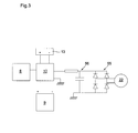
- the lower wheel 40 of the clutch 19 meshes with the gear wheel of the electric generator 22, shown only partially at the figure 5 as well as with a secondary winding wheel 46 mounted integral around a secondary barrel shaft 47.
- a secondary barrel drum 48 is mounted around the secondary barrel shaft 47 being rotatably independent relative thereto. this.
- the secondary barrel drum 47 houses a spiral-shaped secondary energy storage spring (not visible in the figures) and has an external toothing 49.
- the secondary spring has its outer end fixed to the inner wall of the barrel drum. secondary 48 and its inner end fixed to the secondary barrel shaft 47.
- the stiffness of the secondary spring is preferably lower than that of the primary spring 37.
- the secondary barrel drum 48 is held fixed in rotation by the meshing of its teeth 49 with a toothing 50 fixed relative to the shell 12 of the valve 3.
- the assembly constituted by the secondary winding wheel 46, the secondary barrel shaft 47, the secondary barrel drum 48 and the secondary spring form the accumulator
- the secondary drum drum 48 may be closed by a cover.
- the mechanism 17 furthermore comprises a device for detecting the tension of the primary energy storage spring 37.
- This device shown only on the figure 6 , like the power reserve detection clock devices, comprises a differential mechanism 51 cooperating at the input with the primary winding wheel 33 and the primary drum drum 36 and actuating at the output a rotary member 52 of the needle type indicator whose angular position is representative of the tension of the spring 37, that is to say the amount of mechanical energy stored by said spring.
- the rotary member 52 is made of a conductive material, such as copper.
- the rotary member 52 When the spring 37 has reached a predetermined voltage state, consisting of a voltage state judged sufficient, which can be a complete state of winding of the spring 37, the rotary member 52 is in a position where it touches two electrical contacts 53 and thus creates a closed loop which is detected by the processor 8.
- a predetermined voltage state consisting of a voltage state judged sufficient, which can be a complete state of winding of the spring 37
- the mechanism 17 operates as follows. In an initial state, the clutch 19 is in its disengaged position where the upper wheel 39 meshes with the fixed toothing 43, which blocks in rotation the primary barrel drum 36, and the secondary spring is completely unwound (relaxed). Each time the user opens the telephone, the primary winding wheel 33 is rotated by the gear train 18 in a direction tending to raise the primary spring 37. The latter thus accumulates energy as and when phone uses. The pawl 35 prevents the primary winding wheel 33 from rotating in the other direction, which tends to unwind the primary spring 37, and blocks the gear train 18 when closing the phone.
- the slidable flange in the primary barrel drum 36 prevents overvoltage of the primary spring 37 in the event that the phone is opened while the primary spring 37 is fully raised.
- the processor 8 puts the clutch 19 in its engaged position where the upper wheel 39 no longer meshes with the fixed toothing 43, which releases the primary drum drum 36 which starts to rotate under the effect of the expansion of the primary spring 37.
- the lower wheel 40 of the clutch 19, driven by the upper wheel 39 itself driven by the primary drum drum 36 drives the wheel, therefore the rotor, of the electric generator 22 and the wheel secondary winding 46 in a direction tending to raise the secondary spring.
- the primary spring 37 partially discharges into the electric generator 22 and partly into the secondary spring.
- the secondary spring plays here the role of a brake to slow the unwinding of the primary spring 37 and reduce the torque transmitted to the electric generator 22.
- the unwinding of the primary spring 37 stops when an equilibrium is reached between the tension of the primary spring 37 and the resistance opposed by the electric generator 22 and the secondary spring. At this time, the secondary spring is completely or partially raised and the primary spring 37 is not completely unwound. The time required to reach this equilibrium is known to the processor 8 and corresponds to a predetermined time delay. At the end of this delay, the processor 8 returns the clutch 19 in its disengaged position to again block the primary barrel drum 36. No longer being driven or retained by the clutch 19, the secondary winding wheel 46 rotates in the other direction under the effect of the expansion of the secondary spring, which drives the lower wheel 40 of the clutch 19 and thus the wheel of the electric generator 22. The secondary spring is thus completely or almost completely discharged in the electric generator 22.
- the processor 8 resets the clutch 19 in its engaged position so that the energy remaining in the primary spring 37 is discharged into the electric generator 22 and into the secondary spring until a new equilibrium is reached. Then the processor 8 returns the clutch 19 in its disengaged position to block the primary barrel drum 36 and discharge the secondary spring in the electric generator 22.
- This process can be repeated a number of times until the complete or quasi-reeling complete of the primary spring 37. The number of repetitions of this process can be predetermined. Alternatively, this process could be repeated until a sufficiently low primary spring voltage value of 37 is measured by the device illustrated in FIG. figure 6 .
- the present invention thus makes it possible to store a lot of energy in the primary spring 37 and to release it gradually so as to optimize the recharging of the battery 9, that is to say to avoid that a good part of the energy accumulated by the primary spring 37 is lost for recharging the battery 9 due to the clipping of the charging current normally occurring during such charging.
- the present invention also allows the use of an electric generator 22 of low torque, of the type found in some automatic watches.
- the fact that the secondary spring has a stiffness lower than the stiffness of the primary spring is particularly advantageous in this case, because it reduces the torque transmitted to the electric generator 22 during the phase where the energy of one of the storage springs , namely the secondary spring, is supplied only to the electric generator 22.
- the figure 7 shows a second embodiment of the invention using three barrels, two electric generators and two clutches. More specifically, this second embodiment comprises a hinge wheel 58, a gear train 59 and a primary spring energy accumulator 60 identical to the elements 16, 18 and 20 of the first embodiment and arranged in the same manner. .
- the primary spring energy accumulator 60 thus comprises a primary winding wheel 61 mounted integral around a primary barrel shaft 62 around which is rotatably mounted a primary barrel drum 63 housing a primary barrel spring 64.
- the primary drum drum 63 meshes with an upper wheel 65 of a mobile of a primary clutch 66, which further comprises a lower wheel 67 coaxial with the upper wheel 65.
- the primary clutch 66 differs of the clutch 19 of the first embodiment in that the wheels 65, 67 are permanently integral in rotation.
- the upper wheel 65 can, however, move axially relative to the lower wheel 67. This is achieved for example by splines made on the common shaft of the wheels 65, 67 and cooperating with lugs of the upper wheel 65 allowing the latter to slide along the shaft while remaining integral in rotation with said shaft.
- the axial displacement of the upper wheel 65 can be actuated by a clamp 68 acting on a cone located axially between the wheels 65, 67.
- a closure of the clamp 68 moves the cone and, with it, the upper wheel 65 upwards to against the action of a spring and makes the toothing of the upper wheel 65 into a toothing 69 fixed relative to the shell 12 of the valve 3.
- An opening of the clamp 68 releases the upper wheel 65 to the action of said spring, which makes the upper wheel 65 fall and disengage the latter from the fixed toothing 69.
- the movements of the clamp 68 are controlled by a column wheel 70 driven by an electric motor 71 itself controlled by the processor 8
- the toothing of the primary barrel drum 63 is sufficiently high that the upper wheel 65 meshes permanently with the barrel drum 63, irrespective of its axial position.
- the lower wheel 67 remains fixed axially.
- the lower wheel 67 meshes with the gear wheel of a primary electric generator 72, shown partially on the figure 7 as well as with a secondary winding wheel 73 of a secondary spring energy accumulator 74 identical to the secondary spring energy accumulator 21 of the first embodiment.
- the secondary spring energy accumulator 74 thus comprises, in addition to the secondary winding wheel 73, a secondary barrel drum 75 housing a secondary energy storage spring (not visible in the drawing).
- the secondary drum 75 meshes with the lower wheel 76 of a movable secondary clutch 77, which further comprises an upper wheel 78 coaxial with the lower wheel 76.
- the secondary clutch 77 is identical to the clutch primary 66.
- the upper and lower wheels 78, 76 are integral in rotation and in a position of the clutch 77 these two wheels 78, 76 can rotate while in another position these two wheels 78, 76 are locked in rotation by the meshing of the wheel upper 78 with a toothing 79 fixed relative to the shell 12 of the valve 3.
- the upper wheel 78 meshes with a tertiary drum drum 80 rotatably mounted around an axis 81 fixed relative to the shell 12 of the valve 3.
- the tertiary barrel drum 80 houses a tertiary energy-storage spring 82 in the form of a spiral whose inner end is fixed to the axis 81 and the outer end is attached to the inner wall of the tertiary barrel drum 80.
- the tertiary barrel drum 80, the axis 81 and the tertiary spring 82 form a tertiary spring energy accumulator 83.
- the tertiary barrel drum 80 meshes with the gear wheel of a secondary electric generator 84, shown partially in the drawing.
- the stiffness of the tertiary spring 82 is less than the stiffness of the secondary spring, which is itself lower than the stiffness of the primary spring 64.
- the manual charging mechanism of the mobile phone according to the second embodiment of the invention further comprises a device such as that illustrated in FIG. figure 6 to detect the voltage of the primary energy storage spring 64.
- the mechanism illustrated in figure 7 works in the following way.
- the primary and secondary clutches 66, 77 are in a position where the upper wheel 65 meshes with the fixed toothing 69 and the upper wheel 78 meshes with the fixed toothing 79, which keeps the primary barrel drums and secondary 63, 75 and free the tertiary drum drum 80.
- the primary winding wheel 61 is rotated in a direction tending to raise the primary spring 64. The latter thus accumulates the energy as the phone is used.
- the processor 8 puts the primary clutch 66 in its position where the upper wheel 65 no longer meshes with the fixed toothing 69, this releases the primary drum drum 63 which starts to rotate under the effect of the expansion of the primary spring 64.
- the mobile 65, 67 driven by the primary drum drum 63, rotates the gear wheel, so the rotor, the primary electrical generator 72 and the secondary winding wheel 73 in a direction tending to raise the secondary spring, the secondary drum drum 75 remaining immobile.
- the primary spring 64 thus partially discharges into the primary electrical generator 72 and partly into the secondary spring.
- the primary and secondary clutches 66, 77 change positionally in order to mesh the upper wheel 65 with the fixed toothing 69, to disengage the upper wheel 78 from the fixed toothing 79 and to engage the wheel upper 78 with the tertiary barrel drum 80.
- the secondary spring thus discharges partly into the tertiary spring 82 and partly into the secondary electric generator 84.
- the primary and secondary clutches 66, 77 change positionally to allow the primary spring 64 to discharge into the primary electric generator 72 and the secondary spring and to release the tertiary barrel drum 80. so as to discharge the tertiary spring 82 into the secondary electric generator 84.
- This process can be repeated as many times as necessary for the complete or near-complete discharge of the primary spring 64.
- the tertiary spring energy accumulator 83 of the second embodiment could be omitted and the wheel of the secondary electric generator 84 meshes with the upper wheel 78 of the secondary clutch 77 so that, after having been raised by the discharge of the primary spring 64, the secondary spring discharges completely or almost completely into the secondary electric generator 84.
- the winding mechanism is actuated during the opening of the valve 3; in a variant, said mechanism could be actuated when closing the valve 3 against the base 2.
- the present invention is not limited to any particular type of portable electronic device. It could indeed apply to other portable electronic devices than a mobile phone, for example a personal digital assistant (PDA) or a laptop.
- PDA personal digital assistant
- the present invention could also be applied to portable electronic devices comprising a power source other than a storage battery, for example a simple accumulator element or a capacitor of high capacity.
- the two moving parts whose relative movements allow the primary spring to be reassembled could be the body of the apparatus and a specific manual organ such as a crank, respectively.
- the apparatus could be in two sliding parts relative to each other and a rack carried by one of the parts could cooperate with a wheel carried by the other part to raise the primary spring by the intermediate of a gear train.
Priority Applications (1)
| Application Number | Priority Date | Filing Date | Title |
|---|---|---|---|
| EP10290647A EP2463986A1 (de) | 2010-12-10 | 2010-12-10 | Tragbares elektronisches Gerät |
Applications Claiming Priority (1)
| Application Number | Priority Date | Filing Date | Title |
|---|---|---|---|
| EP10290647A EP2463986A1 (de) | 2010-12-10 | 2010-12-10 | Tragbares elektronisches Gerät |
Publications (1)
| Publication Number | Publication Date |
|---|---|
| EP2463986A1 true EP2463986A1 (de) | 2012-06-13 |
Family
ID=43733231
Family Applications (1)
| Application Number | Title | Priority Date | Filing Date |
|---|---|---|---|
| EP10290647A Withdrawn EP2463986A1 (de) | 2010-12-10 | 2010-12-10 | Tragbares elektronisches Gerät |
Country Status (1)
| Country | Link |
|---|---|
| EP (1) | EP2463986A1 (de) |
Cited By (3)
| Publication number | Priority date | Publication date | Assignee | Title |
|---|---|---|---|---|
| CN104158278A (zh) * | 2014-08-29 | 2014-11-19 | 尹建国 | 一种穿戴式电源蓄电方法及其装置 |
| CN104333173A (zh) * | 2014-11-06 | 2015-02-04 | 刘光 | 一种自动发电方法和装置及其用途 |
| CN106545456A (zh) * | 2016-12-06 | 2017-03-29 | 南通大学 | 一种纯机械调节的稳定输出发电装置 |
Citations (13)
| Publication number | Priority date | Publication date | Assignee | Title |
|---|---|---|---|---|
| US1237216A (en) * | 1915-11-17 | 1917-08-14 | Cornelius E Oeth | Self-winding clock. |
| DE3211114A1 (de) | 1982-03-26 | 1983-10-06 | Eduard Dipl Ing Oettinghaus | Verfahren und vorrichtung zum laden von akkumulatoren-batterien |
| EP0409819A2 (de) | 1989-07-20 | 1991-01-23 | Alcatel Austria Aktiengesellschaft | Tragbares Endgerät der Nachrichtentechnik |
| GB2347800A (en) | 1999-03-10 | 2000-09-13 | Ericsson Telefon Ab L M | Hand powered battery charger |
| JP2003204091A (ja) * | 2002-01-08 | 2003-07-18 | Michio Tsujiura | 携帯電話発電装置 |
| GB2399984A (en) | 2003-03-24 | 2004-09-29 | Matsushita Electric Ind Co Ltd | An auxiliary charging device for mobile equipment comprising a piezo electric charge device within the hinge connecting the casing members of the mobile. |
| US20040204180A1 (en) | 2002-11-05 | 2004-10-14 | Ming-Zhen Liao | Cellular phone with built-in generator |
| EP1582943A1 (de) * | 2004-04-01 | 2005-10-05 | Cartier International B.V. | Uhrwerk mit mehreren Federhäusern |
| US20070147179A1 (en) * | 2005-12-07 | 2007-06-28 | Lange Uhren Gmbh | Timepiece with a constant-force device for acting on an oscillating system |
| EP2015145A1 (de) | 2007-06-11 | 2009-01-14 | Chopard Manufacture SA | Vertikale Kupplungsvorrichtung für Uhr |
| US20100038916A1 (en) * | 2006-10-26 | 2010-02-18 | Tomonari Yomoda | Portable electronic device |
| EP2166419A1 (de) * | 2008-09-18 | 2010-03-24 | Agenhor SA | Uhrwerk, das eine Konstantkraftvorrichtung aufweist |
| EP2219279A1 (de) * | 2009-02-13 | 2010-08-18 | Celsius X Vi Ii | Tragbares elektronisches Gerät |
-
2010
- 2010-12-10 EP EP10290647A patent/EP2463986A1/de not_active Withdrawn
Patent Citations (13)
| Publication number | Priority date | Publication date | Assignee | Title |
|---|---|---|---|---|
| US1237216A (en) * | 1915-11-17 | 1917-08-14 | Cornelius E Oeth | Self-winding clock. |
| DE3211114A1 (de) | 1982-03-26 | 1983-10-06 | Eduard Dipl Ing Oettinghaus | Verfahren und vorrichtung zum laden von akkumulatoren-batterien |
| EP0409819A2 (de) | 1989-07-20 | 1991-01-23 | Alcatel Austria Aktiengesellschaft | Tragbares Endgerät der Nachrichtentechnik |
| GB2347800A (en) | 1999-03-10 | 2000-09-13 | Ericsson Telefon Ab L M | Hand powered battery charger |
| JP2003204091A (ja) * | 2002-01-08 | 2003-07-18 | Michio Tsujiura | 携帯電話発電装置 |
| US20040204180A1 (en) | 2002-11-05 | 2004-10-14 | Ming-Zhen Liao | Cellular phone with built-in generator |
| GB2399984A (en) | 2003-03-24 | 2004-09-29 | Matsushita Electric Ind Co Ltd | An auxiliary charging device for mobile equipment comprising a piezo electric charge device within the hinge connecting the casing members of the mobile. |
| EP1582943A1 (de) * | 2004-04-01 | 2005-10-05 | Cartier International B.V. | Uhrwerk mit mehreren Federhäusern |
| US20070147179A1 (en) * | 2005-12-07 | 2007-06-28 | Lange Uhren Gmbh | Timepiece with a constant-force device for acting on an oscillating system |
| US20100038916A1 (en) * | 2006-10-26 | 2010-02-18 | Tomonari Yomoda | Portable electronic device |
| EP2015145A1 (de) | 2007-06-11 | 2009-01-14 | Chopard Manufacture SA | Vertikale Kupplungsvorrichtung für Uhr |
| EP2166419A1 (de) * | 2008-09-18 | 2010-03-24 | Agenhor SA | Uhrwerk, das eine Konstantkraftvorrichtung aufweist |
| EP2219279A1 (de) * | 2009-02-13 | 2010-08-18 | Celsius X Vi Ii | Tragbares elektronisches Gerät |
Cited By (4)
| Publication number | Priority date | Publication date | Assignee | Title |
|---|---|---|---|---|
| CN104158278A (zh) * | 2014-08-29 | 2014-11-19 | 尹建国 | 一种穿戴式电源蓄电方法及其装置 |
| CN104333173A (zh) * | 2014-11-06 | 2015-02-04 | 刘光 | 一种自动发电方法和装置及其用途 |
| CN106545456A (zh) * | 2016-12-06 | 2017-03-29 | 南通大学 | 一种纯机械调节的稳定输出发电装置 |
| CN106545456B (zh) * | 2016-12-06 | 2019-06-04 | 南通大学 | 一种纯机械调节的稳定输出发电装置 |
Similar Documents
| Publication | Publication Date | Title |
|---|---|---|
| FR2532181A1 (fr) | Enrouleur de ceinture de securite pouvant prendre une position sans tension automatiquement memorisee | |
| EP1588640B1 (de) | Längeneinstellungsvorrichtung eines Bandes, insbesondere für ein Uhrarmband | |
| EP2463986A1 (de) | Tragbares elektronisches Gerät | |
| WO2001071435A1 (fr) | Dispositif de remontage d'une montre | |
| JP2008109803A (ja) | 携帯型電子装置 | |
| EP2735919B1 (de) | Uhrwerk, das eine Schnecke umfasst | |
| EP2746869B1 (de) | Elektrischer Solar-Aufzugmechanismus für automatische Armbanduhr | |
| EP2924515B1 (de) | Handgerät Automatische Aufziehvorrichtung mithilfe des Kronenrads für eine Uhr | |
| CH705079A1 (fr) | Source d'énergie mécanique pour mouvement horloger à couple de sortie prédéfini. | |
| EP2189995B1 (de) | Steuerung eines elektrischen Hoch- oder Mittelspannungsgerätes mit einem verbesserten doppelten Einrastmechanismus und entsprechendes Bestückungsverfahren | |
| EP2219279A1 (de) | Tragbares elektronisches Gerät | |
| CA2059133C (fr) | Dispositif de commande du declenchement temporise d'un mecanisme | |
| FR2503271A1 (fr) | Accumulateur mecanique d'energie et demarreur pour moteurs a combustion interne comprenant cet accumulateur | |
| EP2615503B1 (de) | Steuermechanismus eines Federhaus für Uhrwerk | |
| EP2665881B1 (de) | Sonnenschutz, schliess- oder verdunkelungsvorrichtung mit einer reservestromversorgungseinheit für einen aktuator und verfahren zur steuerung einer derartigen vorrichtung | |
| CH707271A2 (fr) | Mouvement de montre comportant une fusée. | |
| CH692875A5 (fr) | Dispositif d'entraînement d'un générateur et instrument de petit volume muni d'un tel dispositif. | |
| CH710521A2 (fr) | Dispositif de génération d'électricité sur demande pour pièces d'horlogerie. | |
| EP2200260B1 (de) | Tragbares Telefon | |
| CH712451B1 (fr) | Mécanisme de remontage et de mise à l'heure d'un mouvement horloger. | |
| EP1903170A1 (de) | Öffnungshilfe für ein Schloss einer Kraftfahrzeugtür | |
| EP4303667A1 (de) | Vorrichtung zur erzeugung von elektrischer energie für eine uhr | |
| CH709423A2 (fr) | Dispositif de remontage par la couronne pour pièce d'horlogerie. | |
| CH719871A2 (fr) | Dispositif de génération d'énergie électrique pour pièce d'horlogerie. | |
| FR3136044A1 (fr) | Installation électrique autonome d’éclairage de l’intérieur d’un meuble |
Legal Events
| Date | Code | Title | Description |
|---|---|---|---|
| PUAI | Public reference made under article 153(3) epc to a published international application that has entered the european phase |
Free format text: ORIGINAL CODE: 0009012 |
|
| AK | Designated contracting states |
Kind code of ref document: A1 Designated state(s): AL AT BE BG CH CY CZ DE DK EE ES FI FR GB GR HR HU IE IS IT LI LT LU LV MC MK MT NL NO PL PT RO RS SE SI SK SM TR |
|
| AX | Request for extension of the european patent |
Extension state: BA ME |
|
| 17P | Request for examination filed |
Effective date: 20121130 |
|
| GRAP | Despatch of communication of intention to grant a patent |
Free format text: ORIGINAL CODE: EPIDOSNIGR1 |
|
| INTG | Intention to grant announced |
Effective date: 20130830 |
|
| STAA | Information on the status of an ep patent application or granted ep patent |
Free format text: STATUS: THE APPLICATION IS DEEMED TO BE WITHDRAWN |
|
| 18D | Application deemed to be withdrawn |
Effective date: 20140110 |