EP2463664A1 - Messung der Geschwindigkeit, Winkelverschiebung, Position oder Bewegung von Wellen - Google Patents
Messung der Geschwindigkeit, Winkelverschiebung, Position oder Bewegung von Wellen Download PDFInfo
- Publication number
- EP2463664A1 EP2463664A1 EP10194367A EP10194367A EP2463664A1 EP 2463664 A1 EP2463664 A1 EP 2463664A1 EP 10194367 A EP10194367 A EP 10194367A EP 10194367 A EP10194367 A EP 10194367A EP 2463664 A1 EP2463664 A1 EP 2463664A1
- Authority
- EP
- European Patent Office
- Prior art keywords
- shaft
- sensor
- speed
- face
- movement
- Prior art date
- Legal status (The legal status is an assumption and is not a legal conclusion. Google has not performed a legal analysis and makes no representation as to the accuracy of the status listed.)
- Withdrawn
Links
Images


Classifications
-
- G—PHYSICS
- G01—MEASURING; TESTING
- G01P—MEASURING LINEAR OR ANGULAR SPEED, ACCELERATION, DECELERATION, OR SHOCK; INDICATING PRESENCE, ABSENCE, OR DIRECTION, OF MOVEMENT
- G01P3/00—Measuring linear or angular speed; Measuring differences of linear or angular speeds
- G01P3/42—Devices characterised by the use of electric or magnetic means
- G01P3/44—Devices characterised by the use of electric or magnetic means for measuring angular speed
- G01P3/48—Devices characterised by the use of electric or magnetic means for measuring angular speed by measuring frequency of generated current or voltage
- G01P3/481—Devices characterised by the use of electric or magnetic means for measuring angular speed by measuring frequency of generated current or voltage of pulse signals
- G01P3/487—Devices characterised by the use of electric or magnetic means for measuring angular speed by measuring frequency of generated current or voltage of pulse signals delivered by rotating magnets
-
- B—PERFORMING OPERATIONS; TRANSPORTING
- B63—SHIPS OR OTHER WATERBORNE VESSELS; RELATED EQUIPMENT
- B63H—MARINE PROPULSION OR STEERING
- B63H1/00—Propulsive elements directly acting on water
-
- G—PHYSICS
- G01—MEASURING; TESTING
- G01D—MEASURING NOT SPECIALLY ADAPTED FOR A SPECIFIC VARIABLE; ARRANGEMENTS FOR MEASURING TWO OR MORE VARIABLES NOT COVERED IN A SINGLE OTHER SUBCLASS; TARIFF METERING APPARATUS; MEASURING OR TESTING NOT OTHERWISE PROVIDED FOR
- G01D5/00—Mechanical means for transferring the output of a sensing member; Means for converting the output of a sensing member to another variable where the form or nature of the sensing member does not constrain the means for converting; Transducers not specially adapted for a specific variable
- G01D5/12—Mechanical means for transferring the output of a sensing member; Means for converting the output of a sensing member to another variable where the form or nature of the sensing member does not constrain the means for converting; Transducers not specially adapted for a specific variable using electric or magnetic means
- G01D5/14—Mechanical means for transferring the output of a sensing member; Means for converting the output of a sensing member to another variable where the form or nature of the sensing member does not constrain the means for converting; Transducers not specially adapted for a specific variable using electric or magnetic means influencing the magnitude of a current or voltage
- G01D5/142—Mechanical means for transferring the output of a sensing member; Means for converting the output of a sensing member to another variable where the form or nature of the sensing member does not constrain the means for converting; Transducers not specially adapted for a specific variable using electric or magnetic means influencing the magnitude of a current or voltage using Hall-effect devices
- G01D5/145—Mechanical means for transferring the output of a sensing member; Means for converting the output of a sensing member to another variable where the form or nature of the sensing member does not constrain the means for converting; Transducers not specially adapted for a specific variable using electric or magnetic means influencing the magnitude of a current or voltage using Hall-effect devices influenced by the relative movement between the Hall device and magnetic fields
-
- G—PHYSICS
- G01—MEASURING; TESTING
- G01D—MEASURING NOT SPECIALLY ADAPTED FOR A SPECIFIC VARIABLE; ARRANGEMENTS FOR MEASURING TWO OR MORE VARIABLES NOT COVERED IN A SINGLE OTHER SUBCLASS; TARIFF METERING APPARATUS; MEASURING OR TESTING NOT OTHERWISE PROVIDED FOR
- G01D5/00—Mechanical means for transferring the output of a sensing member; Means for converting the output of a sensing member to another variable where the form or nature of the sensing member does not constrain the means for converting; Transducers not specially adapted for a specific variable
- G01D5/12—Mechanical means for transferring the output of a sensing member; Means for converting the output of a sensing member to another variable where the form or nature of the sensing member does not constrain the means for converting; Transducers not specially adapted for a specific variable using electric or magnetic means
- G01D5/244—Mechanical means for transferring the output of a sensing member; Means for converting the output of a sensing member to another variable where the form or nature of the sensing member does not constrain the means for converting; Transducers not specially adapted for a specific variable using electric or magnetic means influencing characteristics of pulses or pulse trains; generating pulses or pulse trains
- G01D5/245—Mechanical means for transferring the output of a sensing member; Means for converting the output of a sensing member to another variable where the form or nature of the sensing member does not constrain the means for converting; Transducers not specially adapted for a specific variable using electric or magnetic means influencing characteristics of pulses or pulse trains; generating pulses or pulse trains using a variable number of pulses in a train
- G01D5/2451—Incremental encoders
-
- G—PHYSICS
- G03—PHOTOGRAPHY; CINEMATOGRAPHY; ANALOGOUS TECHNIQUES USING WAVES OTHER THAN OPTICAL WAVES; ELECTROGRAPHY; HOLOGRAPHY
- G03G—ELECTROGRAPHY; ELECTROPHOTOGRAPHY; MAGNETOGRAPHY
- G03G5/00—Recording members for original recording by exposure, e.g. to light, to heat, to electrons; Manufacture thereof; Selection of materials therefor
-
- G—PHYSICS
- G03—PHOTOGRAPHY; CINEMATOGRAPHY; ANALOGOUS TECHNIQUES USING WAVES OTHER THAN OPTICAL WAVES; ELECTROGRAPHY; HOLOGRAPHY
- G03G—ELECTROGRAPHY; ELECTROPHOTOGRAPHY; MAGNETOGRAPHY
- G03G2215/00—Apparatus for electrophotographic processes
Definitions
- the disclosure relates to improvements in the measurement of shaft speed, angular displacement, position or movement.
- US-B-7579827 describes a speed sensing arrangement for sensing the speed of a transmission input shaft, which includes circumferentially spaced markings about the shaft and a speed sensor that is placed in close proximity to the markings.
- the markings may be incorporated on a target wheel (also know as a speed sensor disc), which is attached to the input shaft.
- a gear ring is provided with a plurality of teeth that define the circumferentially spaced markings.
- Speed sensor discs such as the target wheel referred to above, are typically made from pressed steel plate, with serrations at the edge. The serrations allow the speed sensor to detect rotational movement of the shaft and thus determine how fast the transmission shaft is rotating. Pressed steel plate is generally used for the speed sensor disc in order to keep costs down. In order to fit the speed sensor disc amongst the other components on the transmission shaft, additional componentry, such as a thrust washer, is usually needed. Thrust washers are typically made from better quality steel than the speed sensor disc and are machined to provide a good surface finish. The thrust washer is required since the surface finish of the speed sensor disc is poor and this could potentially damage critical neighbouring components on the shaft.
- the disclosure provides a shaft having an end face and at least one detection mark provided on or in the end face of the shaft to enable the speed, angular displacement, position or movement of the shaft to be detected.
- the disclosure also provides a shaft assembly including a sensing arrangement comprising a shaft having an end face and at least one detection mark provided on or in the end face of the shaft and a sensor positioned at a distance from the shaft end face, said sensor being configured to measure the speed, angular displacement, position or movement of the shaft by sensing movement or the position of the detection marks.
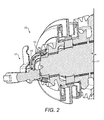
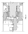
- the shaft assembly 10 illustrated in the Figures generally comprises a transmission shaft 11 and a sensor 17 located for measuring one or all of the shaft speed, angular displacement, position or movement from an axial perspective.
- a gear 12 mounted at one end of the shaft 11 is a gear 12.
- the gear 12 is held in position, for example, by the cone 13 of a taper roller bearing 14.
- At least one detection mark 15 is provided in or on an end face 16 of the shaft 11.
- the shaft 11 has a plurality of spaced apart detection marks 15.
- the detection marks 15 may be machined into the end face 16 or formed in another manner and can, for example, be projections, indents, splines, serrations, holes or markings.
- the detection marks 15 may be offset from the axis of the shaft 11, evenly spaced in a ring around the axis or formed in another pattern which is suitable for detection by the sensor 17.
- the width of the gap between adjacent detection marks 15 may be substantially the same as the width of the detection marks 15.
- one of the detection marks 15 may be omitted from an otherwise regular pattern.
- the sensor 17 is located in a plane axially displaced from the end face 16 at a position whereby the rotation of the detection marks 15 can be detected by the sensor 17.
- the sensor 17 may be mounted to an external part of a casing 18, such as a transmission casing housing the shaft 11.
- a casing 18 such as a transmission casing housing the shaft 11.
- One suitable position is illustrated in Figures 2 to 4 in which the sensor 17 is located axially in line with the shaft 11.
- other mounting positions are acceptable, such as offset from or at an angle to the axis of the shaft 11, as long the rotation of the detection marks 15 can be detected by the sensor 17.
- the senor 17 is mounted with a minimum air gap (i.e. the gap between the end of the shaft 11 and the sensor 17) of 0.5mm.
- a typical maximum gap is 1.5mm, but this may depend on the application and the type of sensor 17 used.
- the sensor 17 may be a passive sensor, such as a magnetic sensor which does not require a power source.
- suitable sensors include variable reluctance sensors, magnetic pick up sensors, pulse generators, timing probes and crankshaft position sensors.
- a variable reluctance sensor usually comprises a permanent magnet, a ferromagnetic pole piece and a pick up coil. As the detection marks 15 pass by the face of the magnet, the magnetic flux passing through the magnet, and therefore the coil, varies. The moving detection marks 15 provide a time varying flux that induces a proportional voltage in the coil.
- the aforementioned shaft 11 and shaft assembly 10 can be used for a variety of applications, including transmissions, gearboxes, transfer boxes, internal and external combustion engines and the like.
- One suitable application is for measurement of the speed of the output shaft in a vehicle transmission, which converts the output of the vehicle engine to rotational movement to drive the vehicle wheels to propel the vehicle.
- vehicle transmission typically includes a gearbox, clutch and various drive shafts.
- the detection marks 15 rotate past the sensor 17.
- the movement of the detection marks 15 causes the sensor 17 to generate an output signal proportional to the speed of rotation of the shaft 11.
Landscapes
- Physics & Mathematics (AREA)
- General Physics & Mathematics (AREA)
- Chemical & Material Sciences (AREA)
- Engineering & Computer Science (AREA)
- Combustion & Propulsion (AREA)
- Mechanical Engineering (AREA)
- Ocean & Marine Engineering (AREA)
- Transmission And Conversion Of Sensor Element Output (AREA)
- Measurement Of Length, Angles, Or The Like Using Electric Or Magnetic Means (AREA)
- Control Of Transmission Device (AREA)
Priority Applications (3)
| Application Number | Priority Date | Filing Date | Title |
|---|---|---|---|
| EP10194367A EP2463664A1 (de) | 2010-12-09 | 2010-12-09 | Messung der Geschwindigkeit, Winkelverschiebung, Position oder Bewegung von Wellen |
| US13/310,953 US9091703B2 (en) | 2010-12-09 | 2011-12-05 | Measurement of shaft speed, angular displacement, position or movement |
| CN 201110401409 CN102564467A (zh) | 2010-12-09 | 2011-12-06 | 对轴的速度、角位移、位置或运动的测量的改良 |
Applications Claiming Priority (1)
| Application Number | Priority Date | Filing Date | Title |
|---|---|---|---|
| EP10194367A EP2463664A1 (de) | 2010-12-09 | 2010-12-09 | Messung der Geschwindigkeit, Winkelverschiebung, Position oder Bewegung von Wellen |
Publications (1)
| Publication Number | Publication Date |
|---|---|
| EP2463664A1 true EP2463664A1 (de) | 2012-06-13 |
Family
ID=43971055
Family Applications (1)
| Application Number | Title | Priority Date | Filing Date |
|---|---|---|---|
| EP10194367A Withdrawn EP2463664A1 (de) | 2010-12-09 | 2010-12-09 | Messung der Geschwindigkeit, Winkelverschiebung, Position oder Bewegung von Wellen |
Country Status (3)
| Country | Link |
|---|---|
| US (1) | US9091703B2 (de) |
| EP (1) | EP2463664A1 (de) |
| CN (1) | CN102564467A (de) |
Families Citing this family (6)
| Publication number | Priority date | Publication date | Assignee | Title |
|---|---|---|---|---|
| DE102011085737A1 (de) * | 2011-11-03 | 2013-05-08 | Continental Teves Ag & Co. Ohg | Winkelsensor auf Wirbelstrombasis |
| US9644735B2 (en) * | 2014-11-24 | 2017-05-09 | Ford Global Technologies, Llc | Powertrain control based on bearing speed |
| DE102017207239A1 (de) * | 2017-04-28 | 2018-10-31 | Volkswagen Aktiengesellschaft | Sensoranordnung zur Erfassung der Drehzahl einer Getriebeeingangswelle |
| US11428116B2 (en) | 2019-11-29 | 2022-08-30 | Pratt & Whitney Canada Corp. | System and method for measuring an axial position of a rotating component of an engine |
| US11420772B2 (en) | 2019-12-17 | 2022-08-23 | Pratt & Whitney Canada Corp. | System and method for determining an axial position of a feedback device |
| CN112963245B (zh) * | 2021-03-16 | 2021-12-21 | 潍柴动力股份有限公司 | 一种发动机转速传感器空气间隙控制装置与控制方法 |
Citations (8)
| Publication number | Priority date | Publication date | Assignee | Title |
|---|---|---|---|---|
| DD124678A1 (de) * | 1976-01-10 | 1977-03-09 | ||
| US4450403A (en) * | 1981-03-02 | 1984-05-22 | Siemens Ag | Method and apparatus for determining rotational speed |
| EP0412780A2 (de) * | 1989-08-11 | 1991-02-13 | John Kirby | Verfahren und Vorrichtung zur Messung der Kraftfahrzeugleistung |
| JPH04105013A (ja) * | 1990-08-24 | 1992-04-07 | Toshiba Corp | 回転同期信号検出装置、回転部可視化装置および回転部変位計測装置 |
| US5426978A (en) * | 1992-10-09 | 1995-06-27 | Mitsubishi Denki Kabushiki Kaisha | Non-destructive axle flaw detecting apparatus |
| US5979248A (en) * | 1994-12-27 | 1999-11-09 | Siemens Aktiengesellschaft | Method and device for determining a power |
| US20050259377A1 (en) * | 2004-05-14 | 2005-11-24 | Peter Gullich | Method for applying a magnetic mark to a rotatable article to be positioned and corresponding device |
| US7579827B2 (en) | 2003-07-25 | 2009-08-25 | Timken Us Corporation | Transmission input shaft speed measuring assembly |
Family Cites Families (11)
| Publication number | Priority date | Publication date | Assignee | Title |
|---|---|---|---|---|
| US3281825A (en) * | 1963-01-25 | 1966-10-25 | United Aircraft Corp | Non-contacting encoder |
| US4377333A (en) * | 1977-08-12 | 1983-03-22 | Canon Kabushiki Kaisha | Recording apparatus |
| US4533902A (en) * | 1983-03-25 | 1985-08-06 | Baker Alan J | Precision angle transducer using nonprecision rotors |
| JPS61283814A (ja) * | 1985-06-10 | 1986-12-13 | Tokyo Keiki Co Ltd | ジヤイロ装置 |
| DE69304102T3 (de) * | 1992-01-31 | 2004-06-03 | Matsushita Electric Industrial Co., Ltd., Kadoma | Gerät mit mehreren synchron rotierenden Wellen |
| FR2772470B1 (fr) * | 1997-12-12 | 2000-03-10 | Electricfil | Capteur de deplacement rotatif equipe de moyens d'assemblage avec un axe d'entrainement concus pour minimiser les effets d'un desalignement de connexion |
| US5979249A (en) | 1998-06-09 | 1999-11-09 | Samsung Electronics Co., Ltd. | Actuator resonance tester for a disk drive |
| US6664780B2 (en) * | 2001-11-02 | 2003-12-16 | Skf Usa Inc. | Unitized tone ring assembly |
| JP4034690B2 (ja) * | 2003-04-28 | 2008-01-16 | ミネベア株式会社 | 2重化バリアブルリラクタンスレゾルバおよびそれを用いた複速度レゾルバシステム |
| DE102004047991A1 (de) * | 2003-10-02 | 2005-06-23 | Aisan Kogyo K.K., Obu | Rotationswinkelsensoren |
| JP2005330942A (ja) * | 2004-05-21 | 2005-12-02 | Toyota Motor Corp | アクチュエータの位置検出装置および内燃機関のバルブリフト可変機構 |
-
2010
- 2010-12-09 EP EP10194367A patent/EP2463664A1/de not_active Withdrawn
-
2011
- 2011-12-05 US US13/310,953 patent/US9091703B2/en not_active Expired - Fee Related
- 2011-12-06 CN CN 201110401409 patent/CN102564467A/zh active Pending
Patent Citations (8)
| Publication number | Priority date | Publication date | Assignee | Title |
|---|---|---|---|---|
| DD124678A1 (de) * | 1976-01-10 | 1977-03-09 | ||
| US4450403A (en) * | 1981-03-02 | 1984-05-22 | Siemens Ag | Method and apparatus for determining rotational speed |
| EP0412780A2 (de) * | 1989-08-11 | 1991-02-13 | John Kirby | Verfahren und Vorrichtung zur Messung der Kraftfahrzeugleistung |
| JPH04105013A (ja) * | 1990-08-24 | 1992-04-07 | Toshiba Corp | 回転同期信号検出装置、回転部可視化装置および回転部変位計測装置 |
| US5426978A (en) * | 1992-10-09 | 1995-06-27 | Mitsubishi Denki Kabushiki Kaisha | Non-destructive axle flaw detecting apparatus |
| US5979248A (en) * | 1994-12-27 | 1999-11-09 | Siemens Aktiengesellschaft | Method and device for determining a power |
| US7579827B2 (en) | 2003-07-25 | 2009-08-25 | Timken Us Corporation | Transmission input shaft speed measuring assembly |
| US20050259377A1 (en) * | 2004-05-14 | 2005-11-24 | Peter Gullich | Method for applying a magnetic mark to a rotatable article to be positioned and corresponding device |
Also Published As
| Publication number | Publication date |
|---|---|
| US20120146629A1 (en) | 2012-06-14 |
| US9091703B2 (en) | 2015-07-28 |
| CN102564467A (zh) | 2012-07-11 |
Similar Documents
| Publication | Publication Date | Title |
|---|---|---|
| US9091703B2 (en) | Measurement of shaft speed, angular displacement, position or movement | |
| US9995599B2 (en) | Rotating sensing apparatus including a sensing plate with holes and a sensing magnet | |
| RU2497087C2 (ru) | Устройство для измерения крутящего момента, передаваемого валом отбора мощности | |
| US7400140B2 (en) | Rotation sensing by detection of magnetised regions provided on a body | |
| US20190063502A1 (en) | Device and method for monitoring a device with a sliding bearing device | |
| US9372065B2 (en) | Combined steering torque-steering angle sensor having magnetic field sensor elements | |
| KR102099587B1 (ko) | 트랜스미션의 샤프트, 특히 풍력 발전소의 방위각 트랜스미션의 출력 샤프트의 토크, 회전 방향 및 회전 속도의 측정 장치 | |
| JP2007500335A (ja) | 速度感知装置 | |
| US20150233736A1 (en) | Measuring arrangement | |
| CA2891532C (en) | Sensor bearing assembly with cover mounted sensor | |
| KR20180121646A (ko) | 그 회전 속도를 측정하기 위한 타겟이 구비된 차동장치 링 기어 및 기어박스 내의 장치 | |
| US20200182899A1 (en) | Rotational speed sensor arrangement | |
| JP2013142702A (ja) | トルク検出用のセンサシステム | |
| JP2021509951A (ja) | センシング装置およびロータおよびセンサの異常有無判断方法 | |
| US10389195B2 (en) | Annular magnets for rotor position estimation | |
| US9038485B2 (en) | Torque sensor bearing arrangement and method | |
| US20110121823A1 (en) | Meshing encoder gear and sensor assembly | |
| RU2020121182A (ru) | Система для определения оборотов в карданных валах, карданный вал, связанный с указанной системой, и способ их определения | |
| JP2017072598A (ja) | 中心ディスクと外側リムとを含むエンジンのためのトルクセンサアセンブリ | |
| ES2924247T3 (es) | Sensor de par | |
| JP7380289B2 (ja) | トルク測定装置及びその製造方法 | |
| CN112673199B (zh) | 传动装置 | |
| CN112567220B (zh) | 致动器系统,尤其用于车辆 | |
| JP2006133045A (ja) | 回転検出装置及び荷重測定装置付転がり軸受ユニット | |
| KR20210142181A (ko) | 변속기 하우징 및 디퍼렌셜 |
Legal Events
| Date | Code | Title | Description |
|---|---|---|---|
| PUAI | Public reference made under article 153(3) epc to a published international application that has entered the european phase |
Free format text: ORIGINAL CODE: 0009012 |
|
| AK | Designated contracting states |
Kind code of ref document: A1 Designated state(s): AL AT BE BG CH CY CZ DE DK EE ES FI FR GB GR HR HU IE IS IT LI LT LU LV MC MK MT NL NO PL PT RO RS SE SI SK SM TR |
|
| AX | Request for extension of the european patent |
Extension state: BA ME |
|
| 17P | Request for examination filed |
Effective date: 20121212 |
|
| 17Q | First examination report despatched |
Effective date: 20180102 |
|
| STAA | Information on the status of an ep patent application or granted ep patent |
Free format text: STATUS: THE APPLICATION IS DEEMED TO BE WITHDRAWN |
|
| 18D | Application deemed to be withdrawn |
Effective date: 20190702 |