EP2463034B1 - Cleaning device for palette forms - Google Patents
Cleaning device for palette forms Download PDFInfo
- Publication number
- EP2463034B1 EP2463034B1 EP20110009621 EP11009621A EP2463034B1 EP 2463034 B1 EP2463034 B1 EP 2463034B1 EP 20110009621 EP20110009621 EP 20110009621 EP 11009621 A EP11009621 A EP 11009621A EP 2463034 B1 EP2463034 B1 EP 2463034B1
- Authority
- EP
- European Patent Office
- Prior art keywords
- cleaned
- brush
- cleaning
- pallet
- cleaning apparatus
- Prior art date
- Legal status (The legal status is an assumption and is not a legal conclusion. Google has not performed a legal analysis and makes no representation as to the accuracy of the status listed.)
- Not-in-force
Links
- 238000004140 cleaning Methods 0.000 title claims description 98
- 230000002745 absorbent Effects 0.000 claims description 27
- 239000002250 absorbent Substances 0.000 claims description 27
- 239000000463 material Substances 0.000 claims description 21
- 239000011178 precast concrete Substances 0.000 claims description 21
- 238000004519 manufacturing process Methods 0.000 claims description 19
- 238000007790 scraping Methods 0.000 claims description 19
- 238000000034 method Methods 0.000 claims description 6
- 238000011109 contamination Methods 0.000 claims description 5
- 238000009434 installation Methods 0.000 claims 2
- 238000009415 formwork Methods 0.000 description 18
- 239000004567 concrete Substances 0.000 description 8
- 239000012459 cleaning agent Substances 0.000 description 6
- 239000000356 contaminant Substances 0.000 description 5
- 230000001413 cellular effect Effects 0.000 description 3
- 239000002184 metal Substances 0.000 description 3
- 239000002023 wood Substances 0.000 description 3
- 238000009826 distribution Methods 0.000 description 2
- 238000001035 drying Methods 0.000 description 2
- 239000002245 particle Substances 0.000 description 2
- 238000005498 polishing Methods 0.000 description 2
- 238000001665 trituration Methods 0.000 description 2
- 229920000426 Microplastic Polymers 0.000 description 1
- 229920006328 Styrofoam Polymers 0.000 description 1
- 239000003795 chemical substances by application Substances 0.000 description 1
- 238000010924 continuous production Methods 0.000 description 1
- 238000005260 corrosion Methods 0.000 description 1
- 230000007797 corrosion Effects 0.000 description 1
- 230000001419 dependent effect Effects 0.000 description 1
- 239000003599 detergent Substances 0.000 description 1
- 230000000694 effects Effects 0.000 description 1
- 230000007774 longterm Effects 0.000 description 1
- 230000003647 oxidation Effects 0.000 description 1
- 238000007254 oxidation reaction Methods 0.000 description 1
- 238000002360 preparation method Methods 0.000 description 1
- 238000003825 pressing Methods 0.000 description 1
- 239000007787 solid Substances 0.000 description 1
- 238000003860 storage Methods 0.000 description 1
- 239000008261 styrofoam Substances 0.000 description 1
Images


Classifications
-
- B08B1/20—
-
- B08B1/32—
-
- B—PERFORMING OPERATIONS; TRANSPORTING
- B28—WORKING CEMENT, CLAY, OR STONE
- B28B—SHAPING CLAY OR OTHER CERAMIC COMPOSITIONS; SHAPING SLAG; SHAPING MIXTURES CONTAINING CEMENTITIOUS MATERIAL, e.g. PLASTER
- B28B7/00—Moulds; Cores; Mandrels
- B28B7/38—Treating surfaces of moulds, cores, or mandrels to prevent sticking
- B28B7/386—Cleaning
Definitions
- the invention relates to a cleaning device for a pallet mold for the production of prefabricated concrete components, comprising at least one scraping element, with the pollution objects of the surface to be cleaned of the pallet shape are schabbar and at least one brush.
- a cleaning device for example in DE 43 26 318 A1 described.
- a trained in the form of a production line pallet circulating system usually includes a Abhebestation for the hardened precast concrete components and a demolition for removing the formwork and a cleaning station for cleaning the pallet form on which the precast concrete component is manufactured, and optionally the formwork and the cured precast concrete component. Subsequently, in principle, a new production cycle for a further precast concrete component can be started with the pallet form.
- the pallet form In this case remain after lifting the hardened precast concrete components and removing the formwork on the pallet form pollution objects of various types.
- the pallet form To ensure the quality of the next concrete precast component to be manufactured, the pallet form must be cleaned before a new occupancy with formwork elements and the subsequent manufacturing process of precast concrete component of the objects of pollution. This is usually done by a cleaning device, which is associated with a cleaning station mentioned above the pallet circulation system.
- cleaning devices of the prior art comprise one or more cleaning agents, which lead to a cleaning of the same by a relative movement between the cleaning agent and the pallet shape. If the cleaning device is basically stationary, the pallet shape moves "under" the cleaning device and is cleaned in a continuous process. On the other hand, there are movably mounted cleaning devices or cleaning devices with movably mounted cleaning agents, wherein the Move cleaning devices or the detergent relative to the stationary pallet shape while cleaning. The cleaning device and / or the cleaning agent can be moved in different directions of movement over the pallet shape.
- a scraping member serves to remove solid debris such as e.g. Concrete residues, Styrofoam pieces, remnants of wood formwork, etc.
- solid debris such as e.g. Concrete residues, Styrofoam pieces, remnants of wood formwork, etc.
- a brush for example, rotates about a substantially parallel to the surface to be cleaned arranged axis.
- This brush can extend over the entire pallet shape and thus serve to clean the entire pallet shape.
- the pallet shape is arranged horizontally, so that the brush rotates in this case in the operating state about a horizontal axis.
- the cleaning device may comprise further variously formed brushes, such as e.g. at least one disc brush rotating about an axis perpendicular to the surface to be cleaned, e.g. Dries dried Betonmilchreste from the pallet form or from the shell elements. Laterally arranged mold brushes are used to clean the fixed or hinged side molds.
- Such contaminated pallet shapes or formwork are particularly a problem when a smooth fair-faced concrete prefabricated component is produced in a next manufacturing cycle, after stripping this exposed concrete prefabricated according to the contaminants more or less well-trained strokes or impressions of dirt by the magnets due to improper cleaned pallet form are recognizable.
- the object of the invention is therefore to provide a cleaning device with which the above-mentioned disadvantages can be avoided and a fast and efficient cleaning of pallet shapes and possibly also of formwork elements in pallet shapes is made possible.
- a surface of a pallet mold to be cleaned can be cleaned for the production of precast concrete components.
- the formwork or formwork elements can be cleaned with the cleaning device.
- it may be provided to fold the formwork elements in a plane parallel to the surface to be cleaned of the pallet form.
- At least one scraping element serves to scrape off soiling articles from the surface of the pallet mold to be cleaned.
- One or more, preferably parallel, scraping elements may be provided.
- the scraper elements can also be lowered to the surface to be cleaned by means of a pivoting movement and / or a vertical movement on the surface to be cleaned and lifted away from it. The scraping takes place by means of a relative movement of the pallet mold and the cleaning device, in particular of the scraping element of the cleaning device.
- a rotating in the operating state brush serves to further clean the surface of dirt, the cleaning surface of the brush according to the circumstances, i. depending on the surface to be cleaned and the objects of contamination, may be selected and, for example, has bristles.
- a feeding device is provided between the scraping element and the brush, from which a pourable and absorbent good can be fed to the surface to be cleaned.
- the pourable and absorbent good are, for example, wood shavings or special plastic granules. It may be provided in each cleaning process optionally, depending on the size of the surface to be cleaned to use a certain amount of pourable and absorbent Good.
- the pourable and absorbent material absorbs the excess oil on the surface to be cleaned. By the rotating brush, the absorbent and pourable material is triturated on the surface to be cleaned and thus dissolves stubborn dirt.
- the brush is formed, for example, as a disc brush.
- a brush has a cleaning surface, which is provided with a suitable cleaning agent such as bristles or a felt layer and has the advantage that during rotation, a high pressure on the surface to be cleaned can be exercised, whereby a particularly good cleaning can be realized.
- a suitable cleaning agent such as bristles or a felt layer
- brushes have the advantage that a large area of the surface to be cleaned is cleaned at the same time. This is especially true for circular cleaning surfaces. In operation, this brush generally rotates about a vertical axis, so the brush is also called a vertical brush.
- the supply device has a distributor, with which the pourable and absorbent material can be distributed on the surface to be cleaned at least over a certain range, so as uniform as possible cleaning a majority of the surface to be cleaned by means of the pouring and absorbent material is possible.
- the distributor can be realized by a special geometric design of the feeder or by other mechanical aids, such as a movable storage of the feeder. But it can also be provided that the distribution of the pourable and absorbent Guts by pouring the Guts from the feeder to the surface to be cleaned automatically.
- the cleaning device has a first brush and a second brush, wherein the first brush is rotatable about an axis arranged substantially perpendicular to the surface to be cleaned and wherein the second brush around a substantially parallel to be cleaned Surface arranged axis is rotatable brush.
- the first brush which is rotatable in the operating state about a substantially perpendicular to the surface to be cleaned, between the second brush, which is rotatable about an axis arranged substantially parallel to the surface to be cleaned axis, and the feeding device arranged.
- the first brush has a cleaning surface, with which the surface to be cleaned can be treated.
- the brush rotating in the operating state about an axis arranged essentially perpendicular to the surface to be cleaned can, for example, have a circular rotating metal disk. That side of the metal disk which faces the surface to be cleaned may be specially designed as a cleaning surface.
- the cleaning surface may be provided with optionally fine bristles or a polishing agent.
- a circular cleaning surface has the particular advantage that the largest possible area of the surface to be cleaned can be cleaned at the same time, while the brush rotating about an axis arranged substantially parallel to the surface to be cleaned essentially has only one line-shaped support.
- Both the rotational movement and the reciprocating motion are made by a known drive unit with a motor.
- the brush is movable relative to the surface to be cleaned, so that with the brush or brush (s) as large a portion of the surface to be cleaned can be cleaned.
- rotating brush serves as a fine cleaning and can be used as a polishing
- the Reinlgungsober Structure is formed as a felt layer with which the surface to be cleaned is treatable.
- the felt layer can be connected to the brush in a simple manner, so that a replacement of the felt layer is possible without problems.
- the at least one scraper element in the operating state about an axis arranged substantially perpendicular to the surface to be cleaned axis rotating brush and additionally or alternatively, the at least one scraper element by means of a pivoting movement and / or a vertical movement on the surface to be cleaned can be arranged.
- An opposite movement causes a lifting of the brush or the scraping element from the surface.
- pourable and absorbent material is in the region of the brush (s), they can be lowered onto the surface to be cleaned and rubbing on the pourable and absorbent material by pressing and rotating or small-scale reciprocating movements, thereby enabling fine cleaning ,
- a dirt container which can be arranged in the region of the brush which rotates about an axis arranged substantially parallel to the surface to be cleaned and can be picked up by the contaminants which are removed from the surface by the brush, for example due to their rotation ,
- bulk and absorbent material such as the wood chips removed and can also be transported in the dirt container.
- the dirt container can empty automatically after each cleaning cycle.
- the cleaning device has at least one brush, which rotates in the operating state about an axis arranged substantially perpendicular to the surface to be cleaned axis, wherein the brush may be formed as a Tollerbürste and having the above advantages.
- the removal of the remaining on the surface pourable and Gutsgut together with the pollution objects can be done instead of means of the axis arranged to be cleaned parallel to a surface rotating brush with a suction device, which the pollution objects and the pourable and absorbent good of the now cleaned Siphoned surface and transferred to a dirt container.
- the brush is arranged in this case between the scraper and the suction device.
- such a suction device can also be provided in addition to the brush arranged around an axis arranged substantially parallel to the surface to be cleaned.
- the cleaning device may further comprise a pre-brush, which is used on the surface to be cleaned in front of the scraper element and coarser objects of contamination to thereby protect the scraper element.
- the invention further relates to a pallet circulation system for the production of prefabricated concrete components, in which the preparation of precast concrete components takes place on pallet forms, said pallet circulating system having a cleaning station with a cleaning device as described above.
- a pallet circulation system in which precast concrete components are produced as pallet forms in a production line is disclosed, for example, in the Austrian patent application AT 506 748 A1 described.
- a cleaning station include a formwork station, a concreting, a Endschalstation and a movement station and a curing and / or drying chamber and a Abhebestation part of the pallet circulation system.
- the cleaning station is automated, especially since several of the remaining stations are automated executable, whereby the efficiency of the production of precast concrete components is further increased.
- the invention further relates to a method for cleaning a pallet mold for the production of prefabricated concrete components with a cleaning device as described above.
- a cleaning device as described above.
- the cleaning device which rotates between the scraper element and the second brush which rotates about an axis arranged substantially parallel to the surface to be cleaned
- the pourable and absorbent material is supplied to the surface to be cleaned and optionally with the distributor device on the distributed to be cleaned surface.
- the distribution is effected automatically by the feeding, for example by a bulk process.
- the cleaning comprises two partial steps, namely a first cleaning with the first brush, which is arranged between the second brush and the supply device, wherein by the rotation of the first brush a movement or trituration of the arranged on the surface to be cleaned pourable and absorbent Guts takes place.
- a second cleaning and optionally removal of the accumulated objects of soiling and the residues of the pourable and absorbent material remaining on the surface takes place.
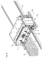
- FIG. 1a shows a perspective view of a cleaning station 13 of a pallet circulation system, wherein in the cleaning station 13, a cleaning device 1 is arranged, with which the surface to be cleaned 3 of the pallet molds 2 is cleaned.
- a cleaning device 1 is arranged, with which the surface to be cleaned 3 of the pallet molds 2 is cleaned.
- the individual pallet molds 2, 2 ', 2 "are moved after the demoulding and lifting of hardened precast concrete components along the arrow direction A by the cleaning station 13 by means of a transport device 16.
- the surface 3 is cleaned after passing through the cleaning station 13, while the Surface 3 is contaminated before the passage with contaminants 11, in particular an oil film due to the production of precast concrete parts.
- the pallet 2 'an already completely cleaned surface 3' while the surface to be cleaned 3 "the pallet form 2" is still completely contaminated ,
- Fig. 1b shows the cleaning station 13 in an enlarged view.
- a coarser objects 11 are first removed with a pre-brush 12.
- a scraping element 4 serves to scrape off further objects of contamination 11. Both the brush 12 and the scraping element 4 can be lifted off the surface 3 to be cleaned by means of a lever mechanism 15 known per se.
- a hopper 14 is arranged, in which the pourable and absorbent material can be filled.
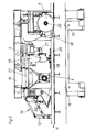
- Fig. 2 shows in a cross-sectional view of the cleaning device 1 with the lever mechanism 15 liftable from the surface to be cleaned 3 Vorbürste 12 and scraping 4, which can be lifted by means of a separate lever mechanism 32 of the surface to be cleaned 3.
- a provided with rollers transport device 16 is used for further transport of the pallet 2 in the direction A.
- the feeder 6 has below the hopper 14 a reservoir 17 for the pour and absorbent Good, which opens into a rotary valve 18, which pours the good on the surface 3 to be cleaned.
- a first brush 9 is arranged, which is provided with a rotating circular cleaning surface 20. The rotation is made possible by a drive 19, wherein the drive 19 and the cleaning surface 20 connected to the drive 19 can be pivoted away from the surface 3 to be cleaned by means of a further lever mechanism 21.
- the cleaning surface 20 is pressed onto the surface to be cleaned 3 and rubbed by the rotation of the sucking and pourable Good, which on the one hand absorbed the oil film and on the other hand finer dirt objects 11 are removed.
- the cleaning surface 20 is formed for example by a felt layer, which is arranged on a plate consisting of a metal.
- a second brush 5 rotating about an axis 22 to be cleaned parallel to the axis 22 serves for further cleaning, as a result of the rotation objects 11 and the material remaining on the pallet mold 2 are conveyed into the collecting container serving as a dirt container 10.
- the rotation of the second brush 5 is also carried out by a known drive.
- Fig. 3a shows the feeder 6 with the reservoir 17 and the hopper 14 in a side view.
- a guard 23 serves to keep unsuitable bodies from being removed from the feeder 6 for cleaning.
- the rotary valve 18 has a cellular wheel 24, which serves to supply the material into the outlet channel 25 and subsequently to the surface 3 to be cleaned.
- the lower part 26 is fixed by means of a lock 27 on the reservoir 17, wherein a pivoting of the lower part 26 about an axis of rotation 31 in unlocked state is possible.
- a seal 28 is arranged between reservoir 17 and lower part 26, a seal 28 is arranged.
- a feed channel 29 and a tear-off edge 30 the material is guided to the cell wheel 24.
- the defined spoiler edge 30, in conjunction with the circumferential recesses 34 on the outside of the cellular wheel 24 ensures that in the medium and long-term operation no blockages or jamming between the reservoir 17 and the rotary valve 18 can form.
- Fig. 3b shows the feeding device 6 in a perspective view.
- a motor 33 serves to drive the rotary valve 18, in particular the cellular wheel 24.
Description
Die Erfindung betrifft eine Reinigungsvorrichtung für eine Palettenform zur Herstellung von Betonfertigbauteilen, umfassend wenigstens ein Schabelement, mit dem Verschmutzungsgegenstände von der zu reinigenden Oberfläche der Palettenform abschabbar sind und wenigstens eine Bürste. Eine derartige Vorrichtung ist beispielsweise in
Dabei verbleiben nach Abheben der ausgehärteten Betonfertigbauteile und dem Entfernen der Schalungen auf der Palettenform Verschmutzungsgegenstände verschiedener Art. Um die Qualität des nächsten herzustellenden Betonfertigbauteils zu gewährleisten, muss die Palettenform vor einer neuerlichen Belegung mit Schalungselementen und dem nachfolgenden Herstellungsvorgang des Betonfertigbauteils von den Verschmutzungsgegenständen gereinigt werden. Dies erfolgt üblicherweise von einer Reinigungsvorrichtung, die einer eingangs erwähnten Reinigungsstation der Palettenumlaufanlage zugeordnet ist.In this case remain after lifting the hardened precast concrete components and removing the formwork on the pallet form pollution objects of various types. To ensure the quality of the next concrete precast component to be manufactured, the pallet form must be cleaned before a new occupancy with formwork elements and the subsequent manufacturing process of precast concrete component of the objects of pollution. This is usually done by a cleaning device, which is associated with a cleaning station mentioned above the pallet circulation system.
Dabei umfassen Reinigungsvorrichtungen des Standes der Technik eines oder mehrere Reinigungsmittel, die durch eine Relativbewegung zwischen dem Reinigungsmittel und der Palettenform zu einer Reinigung derselben führen. Ist die Reinigungsvorrichtung grundsätzlich feststehend ausgebildet, bewegt sich die Palettenform "unter" der Reinigungsvorrichtung und wird im Durchlaufverfahren gereinigt. Andererseits gibt es verfahrbar gelagerte Reinigungsvorrichtungen bzw. Reinigungsvorrichtungen mit bewegbar gelagerten Reinigungsmitteln, wobei sich die Reinigungsvorrichtungen bzw. die Reinigungsmittel relativ zur still stehenden Palettenform bewegen und dabei die Reinigung durchführen. Dabei können die Reinigungsvorrichtung und/oder die Reinigungsmittel in verschiedenen Bewegungsrichtungen über die Palettenform bewegt werden.In this case, cleaning devices of the prior art comprise one or more cleaning agents, which lead to a cleaning of the same by a relative movement between the cleaning agent and the pallet shape. If the cleaning device is basically stationary, the pallet shape moves "under" the cleaning device and is cleaned in a continuous process. On the other hand, there are movably mounted cleaning devices or cleaning devices with movably mounted cleaning agents, wherein the Move cleaning devices or the detergent relative to the stationary pallet shape while cleaning. The cleaning device and / or the cleaning agent can be moved in different directions of movement over the pallet shape.
Ein Schabelement dient zum Entfernen von festen Schmutzteilen, wie z.B. Betonresten, Styroporstücken, Restteilen von Holzschalungen usw. Insbesondere die von dem Schabelement nicht entfernten bzw. durch das Abschaben angefallenen feineren Verschmutzungsgegenstände werden von einer Bürste entfernt, die beispielsweise um eine im Wesentlichen zur zu reinigenden Oberfläche parallel angeordnete Achse rotiert. Diese Bürste kann sich dabei über die gesamte Palettenform erstrecken und somit zur Reinigung der gesamten Palettenform dienen. Üblicherweise ist die Palettenform horizontal angeordnet, sodass die Bürste in diesem Fall im Betriebszustand um eine horizontale Achse rotiert.A scraping member serves to remove solid debris such as e.g. Concrete residues, Styrofoam pieces, remnants of wood formwork, etc. In particular, not removed from the scraper or incurred by the scraping finer pollution objects are removed by a brush, for example, rotates about a substantially parallel to the surface to be cleaned arranged axis. This brush can extend over the entire pallet shape and thus serve to clean the entire pallet shape. Usually, the pallet shape is arranged horizontally, so that the brush rotates in this case in the operating state about a horizontal axis.
Zusätzlich oder alternativ kann die Reinigungsvorrichtung weitere verschiedenartig ausgebildete Bürsten umfassen, wie z.B. zumindest eine um eine senkrecht zur zu reinigenden Oberfläche angeordnete Achse rotierende Tellerbürste, die z.B. eingetrocknete Betonmilchreste von der Palettenform oder auch von den Schalelementen abreibt. Seitlich angeordnete Formbürsten dienen zur Reinigung der fest angeordneten oder klappbaren Seitenschalungen.Additionally or alternatively, the cleaning device may comprise further variously formed brushes, such as e.g. at least one disc brush rotating about an axis perpendicular to the surface to be cleaned, e.g. Dries dried Betonmilchreste from the pallet form or from the shell elements. Laterally arranged mold brushes are used to clean the fixed or hinged side molds.
Zur Herstellung der Betonfertigbauteile ist es nötig, Bereiche der Schalung und der Palettenform einzuölen, um anschließend das ausgehärtete Betonfertigbauteil von der Schalung bzw. der Palettenform zu trennen und vor Korrosion zu schützen. Die mit Schalöl eingeölten Flächen stellen sich für die Reinigung problematisch dar, da durch den Kontakt der eingeölten Flächen mit den oben beschriebenen feineren Verschmutzungsteilen die rotierende Bürste verschmutzt wird und daher auf den Palettenformen, die eigentlich gereinigt werden sollten, trotz Reinigung Ölreste in Längsrichtung der rotierenden Bürste verbleiben. Diese Ölspuren werden dabei mit zunehmender Anzahl an Herstellungszyklen immer stärker, da der Verschmutzungsgrad der rotierenden Bürste zunimmt.To produce the precast concrete components, it is necessary to oil areas of the formwork and the pallet mold, in order subsequently to separate the hardened precast concrete component from the formwork or the pallet form and to protect it from corrosion. The oiled surfaces with form oil pose a problem for the cleaning, as the rotating brush is contaminated by the contact of the oiled surfaces with the finer dirt particles described above and therefore on the pallet shapes that should be cleaned, despite cleaning oil residues in the longitudinal direction of the rotating Brush remain. These traces of oil are becoming increasingly strong as the number of manufacturing cycles increases, since the degree of contamination of the rotating brush increases.
Darüber hinaus ist es mit einer wie oben beschriebenen Reinigungsvorrichtung nur schwer möglich, die in den Ölresten hinterlassenen Abdrücke, die durch Haftmagnete entstehen, welche die Schalungen auf der Palettenform halten, zu entfemen.In addition, with a cleaning device as described above, it is difficult to remove the marks left in the oil residues caused by holding magnets which hold the formwork on the pallet form.
Derart verschmutzte Palettenformen oder auch Schalungen sind insbesondere dann ein Problem, wenn in einem nächsten Herstellungszyklus ein glattes Sichtbetonfertigbauteil hergestellt wird, wobei nach dem Ausschalen dieses Sichtbetonfertigbauteils entsprechend der Verschmutzungen mehr oder weniger stark ausgebildete Striche bzw. Abdrücke der Verschmutzungen durch die Haftmagnete infolge der nicht ordnungsgemäß gereinigten Palettenform erkennbar sind.Such contaminated pallet shapes or formwork are particularly a problem when a smooth fair-faced concrete prefabricated component is produced in a next manufacturing cycle, after stripping this exposed concrete prefabricated according to the contaminants more or less well-trained strokes or impressions of dirt by the magnets due to improper cleaned pallet form are recognizable.
Um diese Verunreinigungen von Sichtbetonfertigbauteilen zu vermeiden, kann vorgesehen sein, nach dem Reinigungsvorgang durch die Reinigungsvorrichtung die Palettenformen und gegebenenfalls auch die Schalungen händisch nachzureinigen, wobei der verunreinigte Ölfilm entfernt wird und eine neuerliche Ölung der Schalung und der Palettenform nötig wird. Diese manuell auszuführende Tätigkeit ist mit einem hohen Arbeitsaufwand verbunden.To avoid these contaminants of exposed concrete prefabricated components, it may be provided to manually clean the pallet forms and possibly also the formwork after the cleaning process by the cleaning device, wherein the contaminated oil film is removed and a renewed oiling of the formwork and the pallet shape is necessary. This manual activity is associated with a high workload.
Darüber hinaus kann es bei der händischen Reinigung vorkommen, dass unter den in verschiedener Form auf der Palettenform angeordneten Schalelementen kein Schalöl vorhanden ist, sodass die Palettenform in diesen Bereichen oxidieren kann, insbesondere wenn die Palettenform längere Zeit, beispielsweise während eines Wochenendes, in der Trockenkammer verbleibt. Diese Oxidation verschmutzt ebenfalls die Palettenform. Derartige Verschmutzungen sind wiederum an den hergestellten Betonfertigbauteilen sichtbar.Moreover, in the case of manual cleaning, there may be no formwork oil among the formwork elements arranged in various shapes on the pallet mold, so that the pallet form can oxidize in these areas, especially if the pallet mold is left in the drying chamber for a longer time, for example during a weekend remains. This oxidation also pollutes the pallet shape. Such contaminants are again visible on the manufactured precast concrete components.
Aufgabe der Erfindung ist es daher, eine Reinigungsvorrichtung zur Verfügung zu stellen, mit der die oben angeführten Nachteile vermieden werden können und eine schnelle und effiziente Reinigung von Palettenformen und gegebenenfalls auch von Schalungselementen bei Palettenformen ermöglicht wird.The object of the invention is therefore to provide a cleaning device with which the above-mentioned disadvantages can be avoided and a fast and efficient cleaning of pallet shapes and possibly also of formwork elements in pallet shapes is made possible.
Dies wird durch eine Reinigungsvorrichtung mit den Merkmalen des Anspruchs 1 gelöst.This is achieved by a cleaning device having the features of
Mit der erfindungsgemäßen Reinigungsvorrichtung kann eine zu reinigende Oberfläche einer Palettenform zur Herstellung von Betonfertigbauteilen gereinigt werden. Darüber hinaus können die Schalungen bzw. Schalungselemente mit der Reinigungsvorrichtung gereinigt werden. Dazu kann vorgesehen sein, die Schalungselemente in eine zur zu reinigenden Oberfläche der Palettenform parallele Ebene zu klappen.With the cleaning device according to the invention, a surface of a pallet mold to be cleaned can be cleaned for the production of precast concrete components. In addition, the formwork or formwork elements can be cleaned with the cleaning device. For this purpose, it may be provided to fold the formwork elements in a plane parallel to the surface to be cleaned of the pallet form.
Wenigstens ein Schabelement dient zur Abschabung von Verschmutzungsgegenständen von der zu reinigenden Oberfläche der Palettenform. Es können dabei eines oder aber auch mehrere, vorzugsweise parallel angeordnete Schabelemente vorgesehen sein. Die Schabelemente können darüber hinaus zur Anordnung auf der zu reinigenden Oberfläche mittels einer Verschwenkbewegung und/oder einer Vertikalbewegung auf die zu reinigende Oberfläche gesenkt und von dieser weggehoben werden. Das Abschaben erfolgt durch eine Relativbewegung der Palettenform und der Reinigungsvorrichtung insbesondere des Schabelements der Reinigungsvorrichtung.At least one scraping element serves to scrape off soiling articles from the surface of the pallet mold to be cleaned. One or more, preferably parallel, scraping elements may be provided. The scraper elements can also be lowered to the surface to be cleaned by means of a pivoting movement and / or a vertical movement on the surface to be cleaned and lifted away from it. The scraping takes place by means of a relative movement of the pallet mold and the cleaning device, in particular of the scraping element of the cleaning device.
Eine im Betriebszustand rotierende Bürste, dient zur weiteren Reinigung der Oberfläche von Verschmutzungsgegenständen, wobei die Reinigungsfläche der Bürste entsprechend den Gegebenheiten, d.h. in Abhängigkeit von der zu reinigenden Oberfläche und den Verschmutzungsgegenständen, ausgewählt sein kann und beispielsweise Borsten aufweist.A rotating in the operating state brush, serves to further clean the surface of dirt, the cleaning surface of the brush according to the circumstances, i. depending on the surface to be cleaned and the objects of contamination, may be selected and, for example, has bristles.
Erfindungsgemäß ist zwischen dem Schabelement und der Bürste eine Zuführvorrichtung vorgesehen, von der ein schütt- und saugfähiges Gut auf die zu reinigende Oberfläche zuführbar ist. Das schütt- und saugfähige Gut sind z.B. Hobelspäne oder auch spezielle Kunststoffgranulate. Es kann dabei vorgesehen sein, bei jedem Reinigungsvorgang gegebenenfalls in Abhängigkeit von der Größe der zu reinigenden Oberfläche eine bestimmte Menge an schütt- und saugfähigem Gut zu verwenden. Das schütt- und saugfähige Gut saugt das überschüssige Öl auf der zu reinigenden Oberfläche auf. Durch die rotierende Bürste wird das saug- und schüttfähige Gut auf der zu reinigenden Oberfläche verrieben und löst dadurch hartnäckigere Verschmutzungen auf.According to the invention, a feeding device is provided between the scraping element and the brush, from which a pourable and absorbent good can be fed to the surface to be cleaned. The pourable and absorbent good are, for example, wood shavings or special plastic granules. It may be provided in each cleaning process optionally, depending on the size of the surface to be cleaned to use a certain amount of pourable and absorbent Good. The pourable and absorbent material absorbs the excess oil on the surface to be cleaned. By the rotating brush, the absorbent and pourable material is triturated on the surface to be cleaned and thus dissolves stubborn dirt.
Weitere vorteilhafte Ausführungen der Erfindung sind in den abhängigen Ansprüchen definiert.Further advantageous embodiments of the invention are defined in the dependent claims.
In einer zweiten Ausführungsform der Erfindung ist die Bürste beispielsweise als Tellerbürste ausgebildet. Eine derartige Bürste weist eine Reinigungsoberfläche auf, die mit einem geeigneten Reinigungsmittel beispielsweise Borsten oder einer Filzschicht versehen ist und hat den Vorteil, dass bei der Rotation ein hoher Druck auf die zu reinigende Oberfläche ausgeübt werden kann, wodurch eine besonders gute Reinigung realisierbar ist. Darüber hinaus haben derartige Bürsten den Vorteil, dass ein großer Bereich der zu reinigenden Oberfläche gleichzeitig reinigbar ist. Dies trifft insbesondere für kreisförmige Reinigungsoberflächen zu. Im Betriebszustand rotiert diese Bürste im Allgemeinen um eine vertikale Achse, sodass die Bürste auch Vertikalbürste genannt wird.In a second embodiment of the invention, the brush is formed, for example, as a disc brush. Such a brush has a cleaning surface, which is provided with a suitable cleaning agent such as bristles or a felt layer and has the advantage that during rotation, a high pressure on the surface to be cleaned can be exercised, whereby a particularly good cleaning can be realized. In addition, such brushes have the advantage that a large area of the surface to be cleaned is cleaned at the same time. This is especially true for circular cleaning surfaces. In operation, this brush generally rotates about a vertical axis, so the brush is also called a vertical brush.
In einer Ausführungsform der Erfindung weist die Zuführvorrichtung eine Verteileinrichtung auf, mit der das schütt- und saugfähige Gut auf der zu reinigenden Oberfläche zumindest auf einem gewissen Bereich verteilt werden kann, damit eine möglichst gleichmäßige Reinigung eines Großteils der zu reinigenden Oberfläche mittels des schütt- und saugfähigen Guts möglich ist. Die Verteileinrichtung kann dabei durch eine spezielle geometrische Ausbildung der Zuführvorrichtung oder durch weitere mechanische Hilfsmittel, wie z.B. eine bewegliche Lagerung der Zuführvorrichtung realisiert werden. Es kann aber auch vorgesehen sein, dass die Verteilung des schütt- und saugfähigen Guts durch ein Schütten des Guts von der Zuführvorrichtung auf die zu reinigende Oberfläche automatisch erfolgt.In one embodiment of the invention, the supply device has a distributor, with which the pourable and absorbent material can be distributed on the surface to be cleaned at least over a certain range, so as uniform as possible cleaning a majority of the surface to be cleaned by means of the pouring and absorbent material is possible. The distributor can be realized by a special geometric design of the feeder or by other mechanical aids, such as a movable storage of the feeder. But it can also be provided that the distribution of the pourable and absorbent Guts by pouring the Guts from the feeder to the surface to be cleaned automatically.
In einer besonders bevorzugten Ausführungsform der Erfindung weist die Reinigungsvorrichtung eine erste Bürste und eine zweite Bürste auf, wobei die erste Bürste um eine im Wesentlichen senkrecht zur zu reinigenden Oberfläche angeordnete Achse rotierbar ist und wobei die zweite Bürste die um eine im Wesentlichen parallel zur zu reinigenden Oberfläche angeordnete Achse rotierbare Bürste ist. Dadurch können die Vorteile beider obigen Bürstenarten kombiniert werden. Insbesondere ist es möglich, verschieden grobe Reinigungsmittel auf der ersten und der zweiten Bürste anzuordnen, sodass eine Grob-, und eine Feinreinigung möglich sind.In a particularly preferred embodiment of the invention, the cleaning device has a first brush and a second brush, wherein the first brush is rotatable about an axis arranged substantially perpendicular to the surface to be cleaned and wherein the second brush around a substantially parallel to be cleaned Surface arranged axis is rotatable brush. Thereby, the advantages of both brush types above can be combined. In particular, it is possible to arrange differently coarse cleaning agents on the first and the second brush, so that a coarse and a fine cleaning are possible.
In einer besonders bevorzugten Ausführungsform der Erfindung ist die erste Bürste, die im Betriebszustand um eine im Wesentlichen senkrecht zur zu reinigenden Oberfläche rotierbar ist, zwischen der zweiten Bürste, die um eine im Wesentlichen parallel zur zu reinigenden Oberfläche angeordnete Achse rotierbar ist, und der Zuführvorrichtung angeordnet. Dabei weist die erste Bürste eine Reinigungsoberfläche auf, mit der die zu reinigende Oberfläche behandelbar ist. Die im Betriebszustand um eine im Wesentlichen senkrecht zur zu reinigenden Oberfläche angeordnete Achse rotierende Bürste kann zum Beispiel eine kreisrunde rotierende Metallscheibe aufweisen. Jene Seite der Metallscheibe, die der zu reinigenden Oberfläche zugewandt ist, kann dabei speziell als Reinigungsoberfläche ausgebildet sein. Die Reinigungsoberfläche kann dabei mit gegebenenfalls feinen Borsten oder einem Poliermittel versehen sein.In a particularly preferred embodiment of the invention, the first brush, which is rotatable in the operating state about a substantially perpendicular to the surface to be cleaned, between the second brush, which is rotatable about an axis arranged substantially parallel to the surface to be cleaned axis, and the feeding device arranged. In this case, the first brush has a cleaning surface, with which the surface to be cleaned can be treated. The brush rotating in the operating state about an axis arranged essentially perpendicular to the surface to be cleaned can, for example, have a circular rotating metal disk. That side of the metal disk which faces the surface to be cleaned may be specially designed as a cleaning surface. The cleaning surface may be provided with optionally fine bristles or a polishing agent.
Von der rotierenden Reinigungsoberfläche wird das schütt- und saugfähige Gut auf die zu reinigende Oberfläche gedrückt und entfernt durch die Rotation der ersten Bürste Verschmutzungen auf der zu reinigende Oberfläche. Eine kreisrunde Reinigungsoberfläche hat dabei den besonderen Vorteil, dass ein möglichst großer Bereich der zu reinigenden Oberfläche gleichzeitig gereinigt werden kann, während die um eine im Wesentlichen parallel zur zu reinigenden Oberfläche angeordnete Achse rotierende Bürste im Wesentlichen nur eine linienförmige Auflage aufweist.From the rotating cleaning surface, the pourable and absorbent material is pressed onto the surface to be cleaned and removed by the rotation of the first brush soiling on the surface to be cleaned. A circular cleaning surface has the particular advantage that the largest possible area of the surface to be cleaned can be cleaned at the same time, while the brush rotating about an axis arranged substantially parallel to the surface to be cleaned essentially has only one line-shaped support.
Prinzipiell kann auch vorgesehen sein, dass statt der um eine senkrecht zur zu reinigenden Oberfläche angeordnete Achse rotierenden Bürste, wenigstens eine entlang der zu reinigenden Oberfläche hin- und herbewegbare Bürste vorgesehen ist, wobei die Verreibung des schütt- und saugfähigen Gutes auf der zu reinigenden Oberfläche statt durch eine Rotationsbewegung der Bürste durch eine kleinräumige Hin- und Herbewegung realisiert wird.In principle, it can also be provided that instead of the brush arranged to rotate about an axis perpendicular to the surface to be cleaned, at least one brush which can be moved back and forth along the surface to be cleaned is provided, wherein the trituration of the pourable and absorbent material is to be cleaned Surface is realized instead of a rotational movement of the brush by a small-scale back and forth movement.
Sowohl die Rotationsbewegung als auch die Hin- und Herbewegung werden von einer an sich bekannten Antriebseinheit mit einem Motor getätigt. Darüber hinaus kann vorgesehen sein, dass die Bürste relativ zur zu reinigenden Oberfläche verfahrbar ist, damit mit der oder den Bürste(n) ein möglichst großer Teil der zu reinigenden Oberfläche reinigbar ist.Both the rotational movement and the reciprocating motion are made by a known drive unit with a motor. In addition, it can be provided that the brush is movable relative to the surface to be cleaned, so that with the brush or brush (s) as large a portion of the surface to be cleaned can be cleaned.
Je nach Ausbildung der Reinigungsoberfläche dient die im Betriebszustand um eine im wesentlichen senkrecht zur zu reinigenden Oberfläche angeordnete Achse rotierende Bürste als Feinreinigung und kann als Polierelement verwendet werden, wobei in einer Ausführungsform der Erfindung die Reinlgungsoberfläche als Filzschicht ausgebildet ist, mit der die zu reinigende Oberfläche behandelbar ist. Die Filzschicht kann dabei in einfacher Weise mit der Bürste verbindbar sein, sodass eine Auswechslung der Filzschicht ohne Probleme möglich ist.Depending on the design of the cleaning surface serving in the operating state about a substantially perpendicular to the surface to be cleaned axis rotating brush serves as a fine cleaning and can be used as a polishing, wherein in one embodiment of the invention, the Reinlgungsoberfläche is formed as a felt layer with which the surface to be cleaned is treatable. The felt layer can be connected to the brush in a simple manner, so that a replacement of the felt layer is possible without problems.
In einer weiteren Ausführungsform der Erfindung sind die im Betriebszustand um eine im Wesentlichen senkrecht zur zu reinigenden Oberfläche angeordnete Achse rotierende Bürste und zusätzlich oder alternativ das wenigstens eine Schabelement mittels mit einer Verschwenkbewegung und/oder einer Vertikalbewegung auf der zu reinigenden Oberfläche anordenbar. Eine entgegengesetzte Bewegung bewirkt ein Wegheben der Bürste bzw. des Schabelements von der Oberfläche.In a further embodiment of the invention, in the operating state about an axis arranged substantially perpendicular to the surface to be cleaned axis rotating brush and additionally or alternatively, the at least one scraper element by means of a pivoting movement and / or a vertical movement on the surface to be cleaned can be arranged. An opposite movement causes a lifting of the brush or the scraping element from the surface.
Befindet sich das schütt- und saugfähige Gut im Bereich der Bürste(n) können diese auf die zu reinigende Oberfläche abgesenkt werden und durch ein Andrücken und eine Rotations- oder kleinräumige Hin- und Herbewegungen das schütt- und saugfähige Gut verreiben und dadurch die Feinreinigung ermöglichen.If the pourable and absorbent material is in the region of the brush (s), they can be lowered onto the surface to be cleaned and rubbing on the pourable and absorbent material by pressing and rotating or small-scale reciprocating movements, thereby enabling fine cleaning ,
In einer weiteren Ausführungsform der Erfindung ist ein Schmutzbehälter vorgesehen, der im Bereich der um eine im Wesentlichen parallel zur zu reinigenden Oberfläche angeordnete Achse rotierenden Bürste anordenbar ist und von dem Verschmutzungsgegenstände aufnehmbar sind, die von der Bürste beispielsweise infolge deren Rotation von der Oberfläche entfernt werden. Darüber hinaus werden von dieser Bürste auch das auf der zu reinigenden Oberfläche verbliebene schütt- und saugfähige Gut, wie beispielsweise die Holzspäne, entfernt und können ebenfalls in den Schmutzbehälter befördert werden. Der Schmutzbehälter kann sich nach jedem Reinigungszyklus automatisch entleeren.In a further embodiment of the invention, a dirt container is provided which can be arranged in the region of the brush which rotates about an axis arranged substantially parallel to the surface to be cleaned and can be picked up by the contaminants which are removed from the surface by the brush, for example due to their rotation , In addition, from this brush and the remaining on the surface to be cleaned bulk and absorbent material, such as the wood chips removed and can also be transported in the dirt container. The dirt container can empty automatically after each cleaning cycle.
In einer weiteren Ausführungsform der Erfindung weist die Reinigungsvorrichtung wenigstens eine Bürste auf, die im Betriebszustand um eine im wesentlichen senkrecht zur zu reinigenden Oberfläche angeordnete Achse rotiert, wobei die Bürste als Tollerbürste ausgebildet sein kann und die oben genannten Vorteile aufweist. Die Entfernung des auf der Oberfläche verbliebenen schütt- und saugfähigen Guts samt der Verschmutzungsgegenstände kann statt mittels der um eine parallel zur zu reinigenden Oberfläche angeordnete Achse rotierenden Bürste auch mit einer Absaugvorrichtung erfolgen, welche die Verschmutzungsgegenstände und das schütt- und saugfähige Gut von der nunmehr gereinigten Oberfläche absaugt und in einen Schmutzbehälter überführt. Die Bürste ist in diesem Fall zwischen dem Schabelement und der Absaugvorrichtung angeordnet. Eine derartige Absaugvorrichtung kann aber auch zusätzlich zu der um eine im Wesentlichen parallel zur zu reinigenden Oberfläche angeordnete Achse rotierenden Bürste vorgesehen sein.In a further embodiment of the invention, the cleaning device has at least one brush, which rotates in the operating state about an axis arranged substantially perpendicular to the surface to be cleaned axis, wherein the brush may be formed as a Tollerbürste and having the above advantages. The removal of the remaining on the surface pourable and Gutsgut together with the pollution objects can be done instead of means of the axis arranged to be cleaned parallel to a surface rotating brush with a suction device, which the pollution objects and the pourable and absorbent good of the now cleaned Siphoned surface and transferred to a dirt container. The brush is arranged in this case between the scraper and the suction device. However, such a suction device can also be provided in addition to the brush arranged around an axis arranged substantially parallel to the surface to be cleaned.
Die Reinigungsvorrichtung kann weiters eine Vorbürste aufweisen, die auf der zu reinigenden Oberfläche vor dem Schabelement zum Einsatz kommt und gröbere Verschmutzungsgegenstände um dadurch das Schabelement zu schützen.The cleaning device may further comprise a pre-brush, which is used on the surface to be cleaned in front of the scraper element and coarser objects of contamination to thereby protect the scraper element.
Die Erfindung betrifft weiters eine Palettenumlaufanlage zur Herstellung von Betonfertigbauteilen, bei der die Herstellung der Betonfertigbauteile auf Palettenformen erfolgt, wobei diese Palettenumlaufanlage eine Reinigungsstation mit einer wie oben beschriebenen Reinigungsvorrichtung aufweist. Eine Palettenumlaufanlage, bei der Betonfertigbauteile als Palettenformen in einer Fertigungsstraße erstellt werden, ist beispielsweise in der österreichischen Patentanmeldung
Bevorzugt ist dabei vorgesehen, dass die Reinigungsstation automatisiert ist, zumal auch mehrere der restlichen Stationen automatisiert ausführbar sind, wodurch die Effizienz der Herstellung der Betonfertigbauteile weiter erhöht wird.Preferably, it is provided that the cleaning station is automated, especially since several of the remaining stations are automated executable, whereby the efficiency of the production of precast concrete components is further increased.
Die Erfindung betrifft weiters ein Verfahren zur Reinigung einer Palettenform zur Herstellung von Betonfertigbauteilen mit einer wie oben beschriebenen Reinigungsvorrichtung. Dabei erfolgt eine Relativbewegung zwischen der Reinigungsvorrichtung und der zu reinigenden Oberfläche, sodass die zu reinigende Oberfläche zunächst vom Schabelement durch Abschaben von gröberen Verschmutzungsgegenständen behandelt wird. In weiterer Folge wird durch die Zuführvorrichtung, die zwischen dem Schabelement und der zweiten Bürste, die um eine im Wesentlichen parallel zur zu reinigenden Oberfläche angeordnete Achse rotiert, das schütt- und saugfähige Gut auf die zu reinigende Oberfläche zugeführt und gegebenenfalls mit der Verteileinrichtung auf der zu reinigenden Oberfläche verteilt. Es kann aber auch vorgesehen sein, dass die Verteilung durch das Zuführen beispielsweise durch einen Schüttvorgang automatisch erfolgt. Durch eine Bewegung des auf der zu reinigenden Oberfläche angeordneten schütt- und saugfähigen Guts mittels der Bürste erfolgt das Reinigen der zu reinigenden Oberfläche. Schließlich werden die angesammelten Verschmutzungsgegenstände und die auf der Oberfläche verbliebenen Reste des schütt- und saugfähigen Guts beispielsweise mit einer Absaugvorrichtung entfernt, sodass die zu reinigende Oberfläche nunmehr gereinigt ist und in sauberem und trockenem Zustand ohne störende Ölspuren für einen weiteren Herstellungszyklus zur Verfügung steht.The invention further relates to a method for cleaning a pallet mold for the production of prefabricated concrete components with a cleaning device as described above. In this case, there is a relative movement between the cleaning device and the surface to be cleaned, so that the surface to be cleaned is first treated by the scraping element by scraping coarser dirt particles. Subsequently, by the feeding device which rotates between the scraper element and the second brush which rotates about an axis arranged substantially parallel to the surface to be cleaned, the pourable and absorbent material is supplied to the surface to be cleaned and optionally with the distributor device on the distributed to be cleaned surface. However, it can also be provided that the distribution is effected automatically by the feeding, for example by a bulk process. By moving the arranged on the surface to be cleaned arranged pourable and absorbent Guts by means of the brush, the cleaning of the surface to be cleaned. Finally, the accumulated objects of pollution and remaining on the surface remnants of the pourable and absorbent Guts example, removed with a suction device, so that the surface to be cleaned is now cleaned and is available in a clean and dry state without annoying traces of oil for another manufacturing cycle.
In einer besonders bevorzugten Ausführungsform umfasst das Reinigen zwei Teilschritte, nämlich ein erstes Reinigen mit der ersten Bürste, die zwischen der zweiten Bürste und der Zuführvorrichtung angeordnet ist, wobei durch die Rotation der ersten Bürste eine Bewegung bzw. Verreibung des auf der zu reinigenden Oberfläche angeordneten schütt- und saugfähigen Guts erfolgt. Durch die im Betriebszustand um eine im Wesentlichen parallel zur zu reinigenden Oberfläche angeordnete Achse rotierende zweite Bürste erfolgt ein zweites Reinigen und gegebenenfalls eine Entfernung der angesammelten Verschmutzungsgegenstände und der auf der Oberfläche verbliebenen Reste des schütt- und saugfähigen Guts.In a particularly preferred embodiment, the cleaning comprises two partial steps, namely a first cleaning with the first brush, which is arranged between the second brush and the supply device, wherein by the rotation of the first brush a movement or trituration of the arranged on the surface to be cleaned pourable and absorbent Guts takes place. By means of the second brush rotating in the operating state around an axis arranged substantially parallel to the surface to be cleaned, a second cleaning and optionally removal of the accumulated objects of soiling and the residues of the pourable and absorbent material remaining on the surface takes place.
Weitere Einzelheiten und Vorteile der vorliegenden Erfindung werden anhand der Figurenbeschreibung unter Bezugnahme auf die Zeichnungen im Folgenden näher erläutert. Darin zeigt:
- Fig. 1a und 1b
- eine perspektivische Ansicht einer Reinigungsstation einer Palettenumlaufanlage sowie eine Detallansicht dazu,
- Fig. 2
- eine Querschnittsdarstellung einer erfindungsgemäßen Reinigungsvorrichtung und
- Fig. 3a und 3b
- eine Seitenansicht und eine perspektivische Ansicht einer Zuführvorrichtung.
- Fig. 1a and 1b
- a perspective view of a cleaning station a pallet circulation system and a detailed view of it,
- Fig. 2
- a cross-sectional view of a cleaning device according to the invention and
- Fig. 3a and 3b
- a side view and a perspective view of a feeder.
Für die Reinigung wird die Reinigungsoberfläche 20 auf die zu reinigende Oberfläche 3 gedrückt und verreibt durch die Rotation das saug- und schüttfähige Gut, wodurch einerseits der Ölfilm aufgesaugt und andererseits feinere Verschmutzungsgegenstände 11 entfernt werden. Die Reinigungsoberfläche 20 ist dabei beispielsweise durch eine Filzschicht gebildet, die an einem aus einem Metall bestehenden Teller angeordnet ist.For cleaning, the cleaning
In weiterer Folge dient eine um eine zur zu reinigenden Oberfläche 3 parallel angeordnete Achse 22 rotierende zweite Bürste 5 zur weiteren Reinigung, wobei in Folge der Rotation Verschmutzungsgegenstände 11 und das auf der Palettenform 2 verbliebene Gut in den als Schmutzbehälter 10 dienenden Auffangbehälter befördert werden. Die Rotation der zweiten Bürste 5 erfolgt ebenso durch einen an sich bekannten Antrieb.As a consequence, a
Die definierte Abrisskante 30 sorgt in Verbindung mit den umlaufenden Aussparungen 34 auf der Außenseite des Zellrads 24 dafür, dass sich im mittel- und langfristigen Betrieb keine Verstopfungen beziehungsweise Verklemmungen zwischen dem Vorratsbehälter 17 und der Zellradschleuse 18 bilden können.The defined
Claims (13)
- A cleaning apparatus (1) for a pallet mould (2) for the production of precast concrete components (8) including at least one scraping element (4) with which contamination items (11) can be scraped off the surface (3) to be cleaned of the pallet mould (2), and at least one brush (5, 9), characterised in that provided between the scraping element (4) and the at least one brush (5, 9) is a feed device (6) for feeding a free-flowing and absorbent material on to the surface (3) to be cleaned, and one of the at least one brush (9) is rotatable about an axis (22) arranged substantially perpendicularly to the surface (3) to be cleaned and has a cleaning surface, wherein the cleaning surface (20) can be pressed on to the surface (3) to be cleaned, which is provided with the free-flowing and absorbent material.
- A cleaning apparatus according to claim 1 characterised in that the feed device (6) has a distributing device for distributing the free-flowing and absorbent material on the surface (3) to be cleaned.
- A cleaning apparatus according to claim 1 or claim 2 characterised in that there are provided a first brush (9) and a second brush (5), wherein the second brush (5) is rotatable about an axis (22) arranged substantially parallel to the surface (3) to be cleaned and wherein the first brush (9) is the brush which is rotatable about an axis arranged substantially perpendicularly to the surface (3) to be cleaned.
- A cleaning apparatus according to claim 3 characterised in that the first brush (9) is arranged between the second brush (5) and the feed device (6).
- A cleaning apparatus according to one of claims 1 to 4 characterised in that the brush (9) which is rotatable about an axis arranged substantially perpendicularly to the surface (3) to be cleaned is in the form of a disk brush.
- A cleaning apparatus according to one of claims 1 to 5 characterised in that the brush (9) which is rotatable about an axis arranged substantially perpendicularly to the surface (3) to be cleaned has a felt layer with which the surface (3) to be cleaned can be treated.
- A cleaning apparatus according to one of claims 1 to 6 characterised in that the scraping element (4) and/or the brush (9) which is rotatable about an axis arranged substantially perpendicularly to the surface (3) to be cleaned can be arranged by means of a pivotal movement and/or a vertical movement on the surface (3) to be cleaned for the cleaning operation.
- A cleaning apparatus according to one of claims 1 to 7 characterised in that there is provided a dirt container (10) by which contaminating items (11) removed from the surface (3) to be cleaned by means of the brush (5, 9) can be received.
- A cleaning apparatus according to one of claims 1 to 8 characterised in that there is provided a suction removal apparatus, by means of which contaminating items (11) can be sucked off the surface (3) to be cleaned.
- A cleaning apparatus according to one of claims 1 to 9 characterised in that there is provided a pre-brush (12) with which the surface (3) to be cleaned can be roughly pre-cleaned up.
- A pallet circulation installation for the production of precast concrete components in which production of the precast concrete components (8) is effected on pallet moulds (2) wherein the pallet circulation installation has a cleaning station having a cleaning apparatus (1) according to one of claims 1 to 10.
- A method of cleaning a pallet mould for the production of precast concrete components with a cleaning apparatus (1) according to one of claims 1 to 10 characterised by the following time sequence of steps:a) scraping off contaminating items (11) from the surface (3) to be cleaned with the scraping element (4),b) feeding a free-flowing and absorbent material with the feed device (6) on to the surface (3) to be cleaned,c) cleaning by a movement of the free-flowing and absorbent material arranged on the surface (3) to be cleaned by means of the brush (5, 9), wherein the cleaning operation includes a movement of the free-flowing and absorbent material disposed on the surface (3) by means of the at least one brush (5, 9), andd) removing the collected contaminating items (11) from the surface (3) to be cleaned.
- A method according to claim 12 with a cleaning apparatus (1) according to one of claims 1 to 10 characterised in that the cleaning operation includes a further cleaning operation by the second brush (5) which rotates about an axis arranged substantially parallel to the surface (3) to be cleaned.
Applications Claiming Priority (1)
| Application Number | Priority Date | Filing Date | Title |
|---|---|---|---|
| ATA2032/2010A AT510415B1 (en) | 2010-12-09 | 2010-12-09 | CLEANING DEVICE FOR PALLET SHAPES |
Publications (3)
| Publication Number | Publication Date |
|---|---|
| EP2463034A2 EP2463034A2 (en) | 2012-06-13 |
| EP2463034A3 EP2463034A3 (en) | 2013-01-30 |
| EP2463034B1 true EP2463034B1 (en) | 2015-04-22 |
Family
ID=45370374
Family Applications (1)
| Application Number | Title | Priority Date | Filing Date |
|---|---|---|---|
| EP20110009621 Not-in-force EP2463034B1 (en) | 2010-12-09 | 2011-12-06 | Cleaning device for palette forms |
Country Status (2)
| Country | Link |
|---|---|
| EP (1) | EP2463034B1 (en) |
| AT (1) | AT510415B1 (en) |
Families Citing this family (15)
| Publication number | Priority date | Publication date | Assignee | Title |
|---|---|---|---|---|
| CN103357600A (en) * | 2013-07-22 | 2013-10-23 | 长沙远大住宅工业有限公司 | Trolley sweeper |
| CN104014494B (en) * | 2014-06-20 | 2016-01-06 | 北方重工集团有限公司 | Tray cleaning device |
| CN108772942A (en) * | 2018-07-13 | 2018-11-09 | 中铁三局集团有限公司 | Cleaning plant and method are automated to the prefabricated mould of I type double-block type sleepers of CRTS |
| CN110608976B (en) * | 2019-10-19 | 2022-05-10 | 杭州鼎昇建材有限公司 | Device for detecting adaptability of concrete admixture |
| CN110721939B (en) * | 2019-10-22 | 2020-07-10 | 浙江工业职业技术学院 | Automatic scarfing cinder device of type that flows prefabricated component mould platform mesa |
| CN110721940B (en) * | 2019-10-22 | 2021-03-26 | 浙江工业职业技术学院 | Table-board residue cleaning and recycling device for movable prefabricated part mold table |
| CN111941605A (en) * | 2020-08-14 | 2020-11-17 | 武汉市人防工程专用设备有限责任公司 | Rapid assembly method for mold of PC prefabricated part |
| CN112642767A (en) * | 2021-02-04 | 2021-04-13 | 陈燕 | Board cleaning device is used in production of polyurethane heated board of customizable cutting |
| CN113102319B (en) * | 2021-03-26 | 2022-07-01 | 桐乡市桐诚科技有限公司 | Automatic maintenance and cleaning equipment and maintenance method for sinker of flat knitting machine |
| CN113263592A (en) * | 2021-05-31 | 2021-08-17 | 安徽华城兴建材科技有限公司 | Cement board forming device |
| CN113733317A (en) * | 2021-08-20 | 2021-12-03 | 安徽绿风环保节能材料有限公司 | Aerated concrete block bottom plate descaling machine |
| CN113883873A (en) * | 2021-10-18 | 2022-01-04 | 安徽云龙粮机有限公司 | High-efficient circulation drying device based on grain processing |
| CN113997393A (en) * | 2021-11-18 | 2022-02-01 | 河北秋旺智能装备有限公司 | Automatic cleaning and oiling device for ceramic tile mould |
| CN114684569A (en) * | 2022-02-28 | 2022-07-01 | 李杰锋 | Building waste intelligence letter sorting equipment based on thing networking is used |
| CN115283326B (en) * | 2022-08-25 | 2023-10-27 | 中交武汉港湾工程设计研究院有限公司 | Automatic cleaning device for special template of bridge tower |
Family Cites Families (13)
| Publication number | Priority date | Publication date | Assignee | Title |
|---|---|---|---|---|
| GB374142A (en) * | 1930-03-12 | 1932-06-06 | American Chem Paint Co | Improvements in or relating to the preparation of metals for painting |
| FR46537E (en) * | 1935-03-25 | 1936-07-09 | Method and machine for pressure dressing the surfaces of hard materials | |
| US3520397A (en) * | 1968-04-15 | 1970-07-14 | Supreme Augers Inc | Particulate material distributing device |
| DD138055B1 (en) * | 1978-07-19 | 1983-05-18 | Richard Krautheim | METHOD AND DEVICE FOR THE AUTOMATIC TAPE CLEANING AND RETURN OF THE DROP MEASURES |
| DE3531438A1 (en) * | 1985-09-03 | 1987-03-05 | Reymann Technik Gmbh | Cleaning and preparation device for the manufacture of plate-shaped concrete parts |
| JPH05254637A (en) * | 1992-03-10 | 1993-10-05 | Oomura Concrete Kk | Transport of ready mixed concrete and device therefor |
| DE4326318A1 (en) * | 1993-08-05 | 1995-02-09 | Ebawe Maschinenbau Gmbh | Method, magazining and cleaning device and large-scale plotter for automatic cleaning and equipping of pallets with transverse rests |
| US5649616A (en) * | 1996-04-11 | 1997-07-22 | Stecklow; Richard L. | Conveyor chain cleaning apparatus |
| DE19728053B4 (en) * | 1997-07-01 | 2004-07-22 | Ralf Schrage | Method of using a brush and brush station for a tube chain conveyor |
| DE20106858U1 (en) * | 2001-04-24 | 2001-07-26 | Fitsch Thomas | Device for removing oil traces |
| ATE532850T1 (en) * | 2005-08-22 | 2011-11-15 | Eurotec Vertriebsgesellschaft M B H | METHOD AND SYSTEM FOR REMOVAL OF OILS, FAT OR SIMILAR HYDROPHOBIC COMPONENTS FROM THE SURFACES OF A SUBSTRATE |
| JP5073953B2 (en) * | 2006-02-28 | 2012-11-14 | 大王製紙株式会社 | Log transport device |
| AT506748A1 (en) | 2008-05-13 | 2009-11-15 | Progress Maschinen & Automatio | METHOD FOR PRODUCING CONCRETE REPRODUCTIVE ELEMENTS ON PALETTE FORMS THROUGHOUT SEVERAL STATIONS OF A MANUFACTURING ROAD |
-
2010
- 2010-12-09 AT ATA2032/2010A patent/AT510415B1/en not_active IP Right Cessation
-
2011
- 2011-12-06 EP EP20110009621 patent/EP2463034B1/en not_active Not-in-force
Also Published As
| Publication number | Publication date |
|---|---|
| EP2463034A2 (en) | 2012-06-13 |
| EP2463034A3 (en) | 2013-01-30 |
| AT510415A4 (en) | 2012-04-15 |
| AT510415B1 (en) | 2012-04-15 |
Similar Documents
| Publication | Publication Date | Title |
|---|---|---|
| EP2463034B1 (en) | Cleaning device for palette forms | |
| EP2922687B1 (en) | Construction of a 3d printing device for producing components | |
| EP3268210B1 (en) | 3d printer having a coater and coater cleaning device and method for cleaning a coater of a 3d printer | |
| EP0615719B1 (en) | Surfaces cleaning machine | |
| DE2602023C3 (en) | Apparatus for processing a printing plate | |
| EP2512691B1 (en) | Method and device for electrostatically separating paint overspray using an absorbant | |
| DE2642928A1 (en) | DEVICE FOR CONTINUOUS TREATMENT OF SMALL PARTS WITH LIQUIDS | |
| EP2922670B1 (en) | Fall duct arrangement with a dual cleaning device, in particular for a device for gluing particles in the course of producing material boards | |
| WO2011067339A1 (en) | Print head cleaning device | |
| DE102013219961A1 (en) | Additive manufacturing plant for the production of vehicle components | |
| DE102020202002A1 (en) | Sludge drying device | |
| DE19545419C2 (en) | Device for the provision, orientation and organization of workpieces | |
| DE1652264A1 (en) | Process for the mechanical surface treatment of work pieces | |
| DE102006054622B4 (en) | Device for cleaning a mixing head of a plant for filling plastic molds | |
| EP2389286B1 (en) | Delimitation of the construction area in a rapid-prototyping system | |
| CH680726A5 (en) | Cleaning device for surface of conveyor belts - has interchangeable brush rollers for different cleaning actions | |
| DE4437763A1 (en) | Method of cleaning steps of escalator | |
| DE2703824A1 (en) | DEVICE FOR THE RECOVERY OF A LIQUID FROM A LIQUID MEDIUM CONTAINING A SOLID | |
| DE4443116C2 (en) | Device for cleaning sheet piles | |
| EP2818424A1 (en) | System and method for cleaning rotatable elements of a labelling unit | |
| DE3807780A1 (en) | Installation for cleaning the foot or the underside of ceramic products | |
| EP2759374A2 (en) | Device and method for grinding at least one separating blade fixed on a blade drum and driven rotating separating blade | |
| DE102013112947A1 (en) | Chute arrangement, apparatus and method for cleaning a chute, in particular in a device for gluing particles | |
| DE4329052A1 (en) | Device for distributing and applying a mould-release agent on shuttering | |
| DE10027023B4 (en) | Devices for cleaning a roller or a cylinder |
Legal Events
| Date | Code | Title | Description |
|---|---|---|---|
| PUAI | Public reference made under article 153(3) epc to a published international application that has entered the european phase |
Free format text: ORIGINAL CODE: 0009012 |
|
| AK | Designated contracting states |
Kind code of ref document: A2 Designated state(s): AL AT BE BG CH CY CZ DE DK EE ES FI FR GB GR HR HU IE IS IT LI LT LU LV MC MK MT NL NO PL PT RO RS SE SI SK SM TR |
|
| AX | Request for extension of the european patent |
Extension state: BA ME |
|
| PUAL | Search report despatched |
Free format text: ORIGINAL CODE: 0009013 |
|
| AK | Designated contracting states |
Kind code of ref document: A3 Designated state(s): AL AT BE BG CH CY CZ DE DK EE ES FI FR GB GR HR HU IE IS IT LI LT LU LV MC MK MT NL NO PL PT RO RS SE SI SK SM TR |
|
| AX | Request for extension of the european patent |
Extension state: BA ME |
|
| RIC1 | Information provided on ipc code assigned before grant |
Ipc: B28B 7/38 20060101ALI20121221BHEP Ipc: B08B 1/02 20060101AFI20121221BHEP Ipc: B08B 1/04 20060101ALI20121221BHEP |
|
| 17P | Request for examination filed |
Effective date: 20130717 |
|
| RBV | Designated contracting states (corrected) |
Designated state(s): AL AT BE BG CH CY CZ DE DK EE ES FI FR GB GR HR HU IE IS IT LI LT LU LV MC MK MT NL NO PL PT RO RS SE SI SK SM TR |
|
| 17Q | First examination report despatched |
Effective date: 20130808 |
|
| GRAP | Despatch of communication of intention to grant a patent |
Free format text: ORIGINAL CODE: EPIDOSNIGR1 |
|
| INTG | Intention to grant announced |
Effective date: 20150120 |
|
| GRAS | Grant fee paid |
Free format text: ORIGINAL CODE: EPIDOSNIGR3 |
|
| GRAA | (expected) grant |
Free format text: ORIGINAL CODE: 0009210 |
|
| AK | Designated contracting states |
Kind code of ref document: B1 Designated state(s): AL AT BE BG CH CY CZ DE DK EE ES FI FR GB GR HR HU IE IS IT LI LT LU LV MC MK MT NL NO PL PT RO RS SE SI SK SM TR |
|
| REG | Reference to a national code |
Ref country code: GB Ref legal event code: FG4D Free format text: NOT ENGLISH |
|
| REG | Reference to a national code |
Ref country code: CH Ref legal event code: EP |
|
| REG | Reference to a national code |
Ref country code: AT Ref legal event code: REF Ref document number: 722895 Country of ref document: AT Kind code of ref document: T Effective date: 20150515 |
|
| REG | Reference to a national code |
Ref country code: IE Ref legal event code: FG4D Free format text: LANGUAGE OF EP DOCUMENT: GERMAN |
|
| REG | Reference to a national code |
Ref country code: DE Ref legal event code: R096 Ref document number: 502011006631 Country of ref document: DE Effective date: 20150603 |
|
| REG | Reference to a national code |
Ref country code: LT Ref legal event code: MG4D |
|
| PG25 | Lapsed in a contracting state [announced via postgrant information from national office to epo] |
Ref country code: ES Free format text: LAPSE BECAUSE OF FAILURE TO SUBMIT A TRANSLATION OF THE DESCRIPTION OR TO PAY THE FEE WITHIN THE PRESCRIBED TIME-LIMIT Effective date: 20150422 Ref country code: LT Free format text: LAPSE BECAUSE OF FAILURE TO SUBMIT A TRANSLATION OF THE DESCRIPTION OR TO PAY THE FEE WITHIN THE PRESCRIBED TIME-LIMIT Effective date: 20150422 Ref country code: HR Free format text: LAPSE BECAUSE OF FAILURE TO SUBMIT A TRANSLATION OF THE DESCRIPTION OR TO PAY THE FEE WITHIN THE PRESCRIBED TIME-LIMIT Effective date: 20150422 Ref country code: PT Free format text: LAPSE BECAUSE OF FAILURE TO SUBMIT A TRANSLATION OF THE DESCRIPTION OR TO PAY THE FEE WITHIN THE PRESCRIBED TIME-LIMIT Effective date: 20150824 Ref country code: NO Free format text: LAPSE BECAUSE OF FAILURE TO SUBMIT A TRANSLATION OF THE DESCRIPTION OR TO PAY THE FEE WITHIN THE PRESCRIBED TIME-LIMIT Effective date: 20150722 |
|
| PG25 | Lapsed in a contracting state [announced via postgrant information from national office to epo] |
Ref country code: RS Free format text: LAPSE BECAUSE OF FAILURE TO SUBMIT A TRANSLATION OF THE DESCRIPTION OR TO PAY THE FEE WITHIN THE PRESCRIBED TIME-LIMIT Effective date: 20150422 Ref country code: GR Free format text: LAPSE BECAUSE OF FAILURE TO SUBMIT A TRANSLATION OF THE DESCRIPTION OR TO PAY THE FEE WITHIN THE PRESCRIBED TIME-LIMIT Effective date: 20150723 Ref country code: LV Free format text: LAPSE BECAUSE OF FAILURE TO SUBMIT A TRANSLATION OF THE DESCRIPTION OR TO PAY THE FEE WITHIN THE PRESCRIBED TIME-LIMIT Effective date: 20150422 Ref country code: IS Free format text: LAPSE BECAUSE OF FAILURE TO SUBMIT A TRANSLATION OF THE DESCRIPTION OR TO PAY THE FEE WITHIN THE PRESCRIBED TIME-LIMIT Effective date: 20150822 |
|
| REG | Reference to a national code |
Ref country code: FR Ref legal event code: PLFP Year of fee payment: 5 |
|
| REG | Reference to a national code |
Ref country code: DE Ref legal event code: R097 Ref document number: 502011006631 Country of ref document: DE |
|
| PG25 | Lapsed in a contracting state [announced via postgrant information from national office to epo] |
Ref country code: DK Free format text: LAPSE BECAUSE OF FAILURE TO SUBMIT A TRANSLATION OF THE DESCRIPTION OR TO PAY THE FEE WITHIN THE PRESCRIBED TIME-LIMIT Effective date: 20150422 Ref country code: EE Free format text: LAPSE BECAUSE OF FAILURE TO SUBMIT A TRANSLATION OF THE DESCRIPTION OR TO PAY THE FEE WITHIN THE PRESCRIBED TIME-LIMIT Effective date: 20150422 |
|
| PLBE | No opposition filed within time limit |
Free format text: ORIGINAL CODE: 0009261 |
|
| STAA | Information on the status of an ep patent application or granted ep patent |
Free format text: STATUS: NO OPPOSITION FILED WITHIN TIME LIMIT |
|
| PG25 | Lapsed in a contracting state [announced via postgrant information from national office to epo] |
Ref country code: SK Free format text: LAPSE BECAUSE OF FAILURE TO SUBMIT A TRANSLATION OF THE DESCRIPTION OR TO PAY THE FEE WITHIN THE PRESCRIBED TIME-LIMIT Effective date: 20150422 Ref country code: CZ Free format text: LAPSE BECAUSE OF FAILURE TO SUBMIT A TRANSLATION OF THE DESCRIPTION OR TO PAY THE FEE WITHIN THE PRESCRIBED TIME-LIMIT Effective date: 20150422 Ref country code: PL Free format text: LAPSE BECAUSE OF FAILURE TO SUBMIT A TRANSLATION OF THE DESCRIPTION OR TO PAY THE FEE WITHIN THE PRESCRIBED TIME-LIMIT Effective date: 20150422 Ref country code: RO Free format text: LAPSE BECAUSE OF NON-PAYMENT OF DUE FEES Effective date: 20150422 |
|
| 26N | No opposition filed |
Effective date: 20160125 |
|
| PG25 | Lapsed in a contracting state [announced via postgrant information from national office to epo] |
Ref country code: IT Free format text: LAPSE BECAUSE OF FAILURE TO SUBMIT A TRANSLATION OF THE DESCRIPTION OR TO PAY THE FEE WITHIN THE PRESCRIBED TIME-LIMIT Effective date: 20150422 |
|
| PG25 | Lapsed in a contracting state [announced via postgrant information from national office to epo] |
Ref country code: SI Free format text: LAPSE BECAUSE OF FAILURE TO SUBMIT A TRANSLATION OF THE DESCRIPTION OR TO PAY THE FEE WITHIN THE PRESCRIBED TIME-LIMIT Effective date: 20150422 |
|
| PG25 | Lapsed in a contracting state [announced via postgrant information from national office to epo] |
Ref country code: MC Free format text: LAPSE BECAUSE OF FAILURE TO SUBMIT A TRANSLATION OF THE DESCRIPTION OR TO PAY THE FEE WITHIN THE PRESCRIBED TIME-LIMIT Effective date: 20150422 Ref country code: LU Free format text: LAPSE BECAUSE OF FAILURE TO SUBMIT A TRANSLATION OF THE DESCRIPTION OR TO PAY THE FEE WITHIN THE PRESCRIBED TIME-LIMIT Effective date: 20151206 |
|
| REG | Reference to a national code |
Ref country code: CH Ref legal event code: PL |
|
| GBPC | Gb: european patent ceased through non-payment of renewal fee |
Effective date: 20151206 |
|
| REG | Reference to a national code |
Ref country code: IE Ref legal event code: MM4A |
|
| PG25 | Lapsed in a contracting state [announced via postgrant information from national office to epo] |
Ref country code: GB Free format text: LAPSE BECAUSE OF NON-PAYMENT OF DUE FEES Effective date: 20151206 Ref country code: LI Free format text: LAPSE BECAUSE OF NON-PAYMENT OF DUE FEES Effective date: 20151231 Ref country code: IE Free format text: LAPSE BECAUSE OF NON-PAYMENT OF DUE FEES Effective date: 20151206 Ref country code: CH Free format text: LAPSE BECAUSE OF NON-PAYMENT OF DUE FEES Effective date: 20151231 |
|
| REG | Reference to a national code |
Ref country code: FR Ref legal event code: PLFP Year of fee payment: 6 |
|
| PG25 | Lapsed in a contracting state [announced via postgrant information from national office to epo] |
Ref country code: BG Free format text: LAPSE BECAUSE OF FAILURE TO SUBMIT A TRANSLATION OF THE DESCRIPTION OR TO PAY THE FEE WITHIN THE PRESCRIBED TIME-LIMIT Effective date: 20150422 Ref country code: SM Free format text: LAPSE BECAUSE OF FAILURE TO SUBMIT A TRANSLATION OF THE DESCRIPTION OR TO PAY THE FEE WITHIN THE PRESCRIBED TIME-LIMIT Effective date: 20150422 Ref country code: HU Free format text: LAPSE BECAUSE OF FAILURE TO SUBMIT A TRANSLATION OF THE DESCRIPTION OR TO PAY THE FEE WITHIN THE PRESCRIBED TIME-LIMIT; INVALID AB INITIO Effective date: 20111206 |
|
| PG25 | Lapsed in a contracting state [announced via postgrant information from national office to epo] |
Ref country code: SE Free format text: LAPSE BECAUSE OF FAILURE TO SUBMIT A TRANSLATION OF THE DESCRIPTION OR TO PAY THE FEE WITHIN THE PRESCRIBED TIME-LIMIT Effective date: 20150422 Ref country code: CY Free format text: LAPSE BECAUSE OF FAILURE TO SUBMIT A TRANSLATION OF THE DESCRIPTION OR TO PAY THE FEE WITHIN THE PRESCRIBED TIME-LIMIT Effective date: 20150422 |
|
| PG25 | Lapsed in a contracting state [announced via postgrant information from national office to epo] |
Ref country code: MT Free format text: LAPSE BECAUSE OF FAILURE TO SUBMIT A TRANSLATION OF THE DESCRIPTION OR TO PAY THE FEE WITHIN THE PRESCRIBED TIME-LIMIT Effective date: 20150422 Ref country code: TR Free format text: LAPSE BECAUSE OF FAILURE TO SUBMIT A TRANSLATION OF THE DESCRIPTION OR TO PAY THE FEE WITHIN THE PRESCRIBED TIME-LIMIT Effective date: 20150422 |
|
| REG | Reference to a national code |
Ref country code: FR Ref legal event code: PLFP Year of fee payment: 7 |
|
| REG | Reference to a national code |
Ref country code: AT Ref legal event code: MM01 Ref document number: 722895 Country of ref document: AT Kind code of ref document: T Effective date: 20161206 |
|
| PG25 | Lapsed in a contracting state [announced via postgrant information from national office to epo] |
Ref country code: AT Free format text: LAPSE BECAUSE OF NON-PAYMENT OF DUE FEES Effective date: 20161206 |
|
| PG25 | Lapsed in a contracting state [announced via postgrant information from national office to epo] |
Ref country code: MK Free format text: LAPSE BECAUSE OF FAILURE TO SUBMIT A TRANSLATION OF THE DESCRIPTION OR TO PAY THE FEE WITHIN THE PRESCRIBED TIME-LIMIT Effective date: 20150422 |
|
| PG25 | Lapsed in a contracting state [announced via postgrant information from national office to epo] |
Ref country code: AL Free format text: LAPSE BECAUSE OF FAILURE TO SUBMIT A TRANSLATION OF THE DESCRIPTION OR TO PAY THE FEE WITHIN THE PRESCRIBED TIME-LIMIT Effective date: 20150422 |
|
| PGFP | Annual fee paid to national office [announced via postgrant information from national office to epo] |
Ref country code: NL Payment date: 20191126 Year of fee payment: 9 Ref country code: FI Payment date: 20191127 Year of fee payment: 9 |
|
| PGFP | Annual fee paid to national office [announced via postgrant information from national office to epo] |
Ref country code: FR Payment date: 20191230 Year of fee payment: 9 Ref country code: BE Payment date: 20191126 Year of fee payment: 9 |
|
| REG | Reference to a national code |
Ref country code: FI Ref legal event code: MAE |
|
| PG25 | Lapsed in a contracting state [announced via postgrant information from national office to epo] |
Ref country code: FI Free format text: LAPSE BECAUSE OF NON-PAYMENT OF DUE FEES Effective date: 20201206 |
|
| REG | Reference to a national code |
Ref country code: NL Ref legal event code: MM Effective date: 20210101 |
|
| REG | Reference to a national code |
Ref country code: BE Ref legal event code: MM Effective date: 20201231 |
|
| PG25 | Lapsed in a contracting state [announced via postgrant information from national office to epo] |
Ref country code: NL Free format text: LAPSE BECAUSE OF NON-PAYMENT OF DUE FEES Effective date: 20210101 |
|
| PG25 | Lapsed in a contracting state [announced via postgrant information from national office to epo] |
Ref country code: FR Free format text: LAPSE BECAUSE OF NON-PAYMENT OF DUE FEES Effective date: 20201231 |
|
| PGFP | Annual fee paid to national office [announced via postgrant information from national office to epo] |
Ref country code: DE Payment date: 20211230 Year of fee payment: 11 |
|
| PG25 | Lapsed in a contracting state [announced via postgrant information from national office to epo] |
Ref country code: BE Free format text: LAPSE BECAUSE OF NON-PAYMENT OF DUE FEES Effective date: 20201231 |
|
| REG | Reference to a national code |
Ref country code: DE Ref legal event code: R119 Ref document number: 502011006631 Country of ref document: DE |
|
| PG25 | Lapsed in a contracting state [announced via postgrant information from national office to epo] |
Ref country code: DE Free format text: LAPSE BECAUSE OF NON-PAYMENT OF DUE FEES Effective date: 20230701 |