CN112642767A - Board cleaning device is used in production of polyurethane heated board of customizable cutting - Google Patents
Board cleaning device is used in production of polyurethane heated board of customizable cutting Download PDFInfo
- Publication number
- CN112642767A CN112642767A CN202110152765.7A CN202110152765A CN112642767A CN 112642767 A CN112642767 A CN 112642767A CN 202110152765 A CN202110152765 A CN 202110152765A CN 112642767 A CN112642767 A CN 112642767A
- Authority
- CN
- China
- Prior art keywords
- rods
- supporting
- rod
- sides
- sliding
- Prior art date
- Legal status (The legal status is an assumption and is not a legal conclusion. Google has not performed a legal analysis and makes no representation as to the accuracy of the status listed.)
- Withdrawn
Links
- 238000004140 cleaning Methods 0.000 title claims abstract description 53
- 229920002635 polyurethane Polymers 0.000 title claims abstract description 19
- 239000004814 polyurethane Substances 0.000 title claims abstract description 19
- 238000005520 cutting process Methods 0.000 title claims description 5
- 238000004519 manufacturing process Methods 0.000 title claims description 5
- 238000009413 insulation Methods 0.000 claims abstract description 24
- 230000000694 effects Effects 0.000 abstract description 14
- 230000007306 turnover Effects 0.000 abstract description 2
- 230000009286 beneficial effect Effects 0.000 abstract 1
- 238000010586 diagram Methods 0.000 description 7
- 230000009471 action Effects 0.000 description 6
- 238000003825 pressing Methods 0.000 description 4
- 230000002508 compound effect Effects 0.000 description 2
- 230000007547 defect Effects 0.000 description 2
- 239000011810 insulating material Substances 0.000 description 2
- 230000002146 bilateral effect Effects 0.000 description 1
- 239000002131 composite material Substances 0.000 description 1
- 150000001875 compounds Chemical class 0.000 description 1
- 238000010276 construction Methods 0.000 description 1
- 239000000463 material Substances 0.000 description 1
- 230000004048 modification Effects 0.000 description 1
- 238000012986 modification Methods 0.000 description 1
- 230000009467 reduction Effects 0.000 description 1
- 229920002994 synthetic fiber Polymers 0.000 description 1
Images


Classifications
-
- B08B1/20—
-
- B08B1/32—
-
- B—PERFORMING OPERATIONS; TRANSPORTING
- B08—CLEANING
- B08B—CLEANING IN GENERAL; PREVENTION OF FOULING IN GENERAL
- B08B13/00—Accessories or details of general applicability for machines or apparatus for cleaning
Abstract
The invention relates to a cleaning device, in particular to a plate surface cleaning device for producing a polyurethane insulation board capable of being cut by customization. The invention aims to provide a plate surface cleaning device for producing a polyurethane insulation plate, which can automatically clean, has a good cleaning effect and is convenient to operate and can be cut by customization. The technical scheme is as follows: a plate surface cleaning device for producing a polyurethane insulation board capable of being cut by a user in a customized mode comprises two support frames; the placing component is arranged between the tops of the supporting frames; the middle part of the placing component is provided with a turnover component; the cleaning component is arranged on the upper part of the placing component. The invention has the beneficial effects that: under the effect of clean subassembly, people place the heated board on placing the board, and the board is placed to the left side promotion, presses the slider downwards, when cleaning brush and heated board contact, can clean the heated board, the effectual work efficiency that has improved people.
Description
Technical Field
The invention relates to a cleaning device, in particular to a plate surface cleaning device for producing a polyurethane insulation board capable of being cut by customization.
Background
The polyurethane heat-insulating material is a synthetic material with excellent performance, has the advantages of high specific strength, small heat conductivity coefficient and the like, is mainly used as a heat-insulating material, and is a structural material.
The heated board adopts multilayer composite construction, before the multilayer is compound, for guaranteeing compound effect, needs to plane the operation to each layer, planes the operation back, scatters some crushed aggregates on the heated board, the compound effect of heated board. After planing, can adopt cleaning device to clean the heated board, people generally are that handheld towel wipes its surface when cleaning the heated board at present, operate inconvenient like this, and clear effect is relatively poor for reduce people's work efficiency, and intensity of labour is big, can take the time hard.
Therefore, it is particularly necessary to design a board cleaning device for producing a polyurethane insulation board, which can automatically clean, has a good cleaning effect and is convenient to operate, and can be cut by customization, so that some troubles and dangers possibly caused by most of manual operations are saved, and the working efficiency is improved, thereby solving the defects.
Disclosure of Invention
In order to overcome the defects of inconvenient operation, poor cleaning effect, reduction in working efficiency of people, high labor intensity and time and labor wasting, the invention aims to provide the plate surface cleaning device for producing the polyurethane insulation board, which can clean automatically, has a good cleaning effect and is convenient to operate and can be cut in a customized mode.
The technical scheme is as follows: the utility model provides a face cleaning device is used in production of polyurethane heated board of customizable cutting, including: two support frames are provided; the placing component is arranged between the tops of the supporting frames; the middle part of the placing component is provided with a turnover component; the cleaning component is arranged on the upper part of the placing component.
As a further preferred solution, the placing assembly comprises: the top of the support frame is symmetrically provided with two sliding groove rods; the bearings are arranged between one sides of the sliding groove rods on the same side in a sliding manner; the first springs are connected between the other side of the bearing on the same side and the chute rod; the two sides of the bearing are provided with first supporting rods; the placing plate is arranged between the upper parts of the first supporting rods in a sliding manner; the second springs are connected between the placing plate and the first supporting rods and are respectively sleeved on the first supporting rods; the two sides of the bottom of the placing plate are rotatably provided with the rollers; wedge-shaped rods are arranged on one sides of the bottoms of the lower side sliding groove rods, and the wedge-shaped rods on the same side are respectively matched with the rollers.
As a further preferable aspect, the flipping unit includes: the bearings are respectively and rotatably provided with a first rotating shaft; the inner sides of the first rotating shafts are both provided with first sliding rods in a sliding manner; the inner sides of the first sliding rods are provided with clamping plates; the third springs are connected between the first slide bar and the first rotating shaft on the same side; the first wedge-shaped blocks are arranged on the two sides of the clamping plate; the stop rods are arranged on one sides of the lower sliding groove rods, and the first wedge blocks on the same side are matched with the stop rods respectively; the outer sides of the first rotating shafts are provided with ratchet gears; the outer sides of one part of the lower sliding groove rod are provided with second supporting groove blocks; the upper sides of the second supporting groove blocks are both provided with ratchet bars in a sliding manner, and the ratchet bars and the ratchet wheels on the same side are matched with each other; and a plurality of fourth springs are arranged between the ratchet bar on the same side and the second supporting groove block.
As a further preferred solution, the cleaning member comprises: the inner sides of the middle parts of the upper sliding groove rods are provided with third supporting groove blocks; the third supporting groove block is provided with a sliding block; the fifth springs are connected between the slide blocks on the same side and the third supporting groove blocks; the cleaning brushes are rotatably arranged between the sliding blocks; the two sides of the cleaning brush are provided with first gears; first racks are arranged between the tops of the first supporting rods on the two sides of the first rack, and the first racks on the same side are meshed with the first gear.
As a further preferable scheme, the device further comprises a clamping assembly, wherein the clamping assembly comprises: the supporting blocks are arranged on two sides of the outer part of the first supporting rod; the clamping rods are arranged on the inner sides of the supporting blocks in a sliding mode, round holes are symmetrically formed in the first rotating shaft, and the clamping rods are matched with the round holes respectively; and the sixth springs are connected between the clamping rods and the supporting blocks and are respectively sleeved on the clamping rods.
As a further preferable scheme, the device further comprises a pressing component, and the pressing component comprises: the tops of the second supporting rods and the third supporting groove blocks are provided with second supporting rods; the top of the second support rod is provided with a top rod in a sliding manner; the outer sides of the bottoms of the ejector rods are provided with second wedge-shaped blocks; two seventh springs are connected between the ejector rod and the second supporting rod on the same side, and the seventh springs are respectively sleeved on the second supporting rod; and the second slide bars are arranged on the outer sides of the first rotating shafts and are matched with the second wedge blocks respectively.
As a further preferable scheme, the device further comprises a driving assembly, wherein the driving assembly comprises: the third supporting rods are symmetrically arranged between the lower sides of the wedge-shaped rods; the air cylinder is arranged between the lower sides of the third supporting rods; the telescopic rod of the cylinder is provided with a second rack; the middle part of one side of each wedge-shaped rod is provided with a fourth supporting rod; a second rotating shaft is rotatably arranged between the lower sides of the fourth supporting rods; the middle part of the second rotating shaft is provided with a second gear, and the second gear is meshed with the second rack; the reels are arranged on two sides of the second rotating shaft; pulleys are rotatably arranged on the upper sides of the wedge-shaped rods; stay cord, homonymy reel all are connected with the stay cord through between pulley and the first bracing piece respectively.
As a further preferred solution, the cleaning brush is detachable.
Compared with the prior art, the invention has the following advantages:
1. under the effect of clean subassembly, people place the heated board on placing the board, and the board is placed in the left side promotion, and people press the slider downwards, and the slider can drive cleaning brush and first gear downstream, can drive first rack when first bracing piece downstream left and move left, and first rack can drive first gear and cleaning brush and rotate, when cleaning brush and heated board contact, can clean the heated board, the effectual work efficiency that improves people.
2. Under the effect of chucking subassembly, when first rotation axis rotates, the epaxial round hole of first rotation can break away from with the kelly, and the kelly can move to the outside, and when first rotation axis rotated one hundred eighty degrees, the round hole can continue to move to the inboard with the kelly cooperation, can drive the kelly to continue to block first rotation axis, makes the pivoted position more accurate at every turn, and the heated board can not take place to deflect because inertial effect.
3. Under the effect of push down the subassembly, when removing when first rotation axis removes, can drive the second slide bar and remove about, when the contact of second slide bar and second wedge, can drive the second wedge and remove downwards, the second wedge can drive the ejector pin and remove downwards, thereby the ejector pin drives the automatic downward movement of slider for people need not manual movement slider, have improved people's efficiency.
4. Under drive assembly's effect, people start the cylinder, when the second rack moves to the left side, can drive second gear, second rotation axis and reel forward rotation, and the reel can drive the stay cord and pass through the pulley and move to the left side, and the stay cord right-hand member can drive first bracing piece and move to the left side to the board is placed to automatic drive and moves to the left side, makes people's operation more simple and convenient.
Drawings
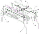
Fig. 1 is a schematic perspective view of the present invention.
Fig. 2 is a schematic perspective view of another angle according to the present invention.
FIG. 3 is a schematic diagram of a first partial structure according to the present invention.
FIG. 4 is a second partial structure diagram of the present invention.
FIG. 5 is a third partial structural diagram of the present invention.
FIG. 6 is a schematic diagram of a fourth partial structure of the present invention.
FIG. 7 is a schematic diagram of a fifth partial structure according to the present invention.
FIG. 8 is a schematic diagram of a sixth partial structure according to the present invention.
FIG. 9 is a schematic diagram of a seventh partial structure according to the present invention.
Number designation in the figures: 1-support frame, 2-placement component, 201-sliding groove rod, 202-bearing, 203-first spring, 204-first support rod, 205-placement plate, 206-second spring, 207-roller, 208-wedge rod, 3-turnover component, 301-first rotating shaft, 302-first sliding rod, 303-clamping plate, 304-third spring, 305-first wedge block, 306-blocking rod, 307-ratchet wheel, 308-second support groove block, 309-ratchet rack, 310-fourth spring, 4-cleaning component, 401-third support groove block, 402-sliding block, 403-fifth spring, 404-cleaning brush, 405-first gear, 406-first rack, 5-clamping component, 501-support block, 502-clamping rod, 503-sixth spring, 6-pressing component, 601-second supporting rod, 602-top rod, 603-second wedge block, 604-seventh spring, 605-second sliding rod, 7-driving component, 701-third supporting rod, 702-air cylinder, 703-second rack, 704-fourth supporting rod, 705-second rotating shaft, 706-second gear, 707-reel, 708-pulley and 709-pull rope.
Detailed Description
The technical solutions in the embodiments of the present invention will be clearly and completely described below with reference to the drawings in the embodiments of the present invention, and it is obvious that the described embodiments are only a part of the embodiments of the present invention, and not all of the embodiments. All other embodiments, which can be derived by a person skilled in the art from the embodiments given herein without making any creative effort, shall fall within the protection scope of the present invention.
Example 1
The utility model provides a customizable polyurethane insulation board production of cutting is with face cleaning device, as shown in figure 1, figure 2, figure 3, figure 4, figure 5 and figure 6, including support frame 1, place subassembly 2, upset subassembly 3 and clean subassembly 4, support frame 1 has two, is equipped with between 1 tops of support frame and places subassembly 2, places 2 middle parts of subassembly and is equipped with upset subassembly 3, places 2 upper portions of subassembly and is equipped with clean subassembly 4.
The placing component 2 comprises a sliding groove rod 201, a bearing 202, a first spring 203, a first support rod 204, a placing plate 205, a second spring 206, a roller 207 and a wedge rod 208, the two sliding groove rods 201 are symmetrically arranged on the front and back of the top of the support frame 1, the bearing 202 is arranged between the right sides of the sliding groove rods 201 on the same side in a sliding mode, the first spring 203 is connected between the left side of the bearing 202 on the same side and the sliding groove rod 201, the first support rod 204 is arranged on the left and right sides of the bearing 202, the placing plate 205 is arranged between the upper portions of the first support rods 204 in a sliding mode, the second spring 206 is connected between the placing plate 205 and the first support rods 204, the second spring 206 is respectively sleeved on the first support rods 204, the roller 207 is arranged on the front and back of the bottom of the placing plate 205 in a rotating mode, the left side of the bottom of the sliding groove.
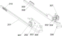
The turning assembly 3 comprises a first rotating shaft 301, a first sliding rod 302, a clamping plate 303, a third spring 304, a first wedge block 305, a stop lever 306, a ratchet gear 307, a second supporting groove block 308, a ratchet bar 309 and a fourth spring 310, wherein the first rotating shaft 301 is rotatably arranged on the bearing 202, the first sliding rod 302 is slidably arranged on the inner side of the first rotating shaft 301, the clamping plate 303 is arranged on the inner side of the first sliding rod 302, the third spring 304 is connected between the first sliding rod 302 and the first rotating shaft 301 on the same side, the first wedge block 305 is arranged on the left side and the right side of the clamping plate 303, the stop lever 306 is arranged on the right side of the lower sliding groove rod 201, the first wedge block 305 on the same side is mutually matched with the stop lever 306, the ratchet gear 307 is arranged on the outer side of the first rotating shaft 301, the second supporting groove block 308 is arranged on the left side of the lower sliding groove rod 201, the ratchet bar 309 is slidably arranged on the upper side of the second supporting groove block 308, the ratchet bar, a plurality of fourth springs 310 are disposed between the ratchet bar 309 and the second supporting groove block 308 on the same side.
The cleaning assembly 4 comprises a third supporting groove block 401, a sliding block 402, a fifth spring 403, a cleaning brush 404, a first gear 405 and a first gear rack 406, the third supporting groove block 401 is arranged on the inner side of the middle of the upper sliding groove rod 201, the sliding block 402 is arranged on the third supporting groove block 401 in a sliding mode, the fifth spring 403 is connected between the sliding block 402 and the third supporting groove block 401 on the same side, the cleaning brush 404 is arranged between the sliding blocks 402 in a rotating mode, the first gear 405 is arranged on the front side and the rear side of the cleaning brush 404, the first gear rack 406 is arranged between the tops of the first supporting rods 204 on the left side and the right side, and the first gear rack 406 and the first gear 405 on the same side are meshed with.
When the insulation board 205 is placed on the placing plate 205, the placing plate 205 is pushed to the left, the first spring 203 is compressed, the first wedge-shaped block 305 is in contact with the stop lever 306 in the initial state, the third spring 304 is in a compressed state, when the placing plate 205 moves to the left, the bearing 202, the first rotating shaft 301, the first sliding rod 302 and the clamping plate 303 are driven to move to the left, when the clamping plate 303 moves to the left, the first wedge-shaped block 305 is driven to move to the left, when the first wedge-shaped block 305 is separated from the stop lever 306, the first sliding rod 302 and the clamping plate 303 are driven to move to the side due to the reset action of the third spring 304, so as to clamp the insulation board, the user presses the sliding block 402 downwards, the fifth spring 403 is compressed, the sliding block 402 drives the cleaning brush 404 and the first gear 405 to move downwards, when the first supporting rod 204 moves to the left, the first rack 406 is driven to move to the left, and the first rack 406 is meshed with the first gear 405, the first gear 405 is driven to rotate, the cleaning brush 404 is driven to rotate by the first gear 405, when the cleaning brush 404 is in contact with the insulation board, the top surface of the insulation board is cleaned, when the placing plate 205 continues to move leftwards, the roller 207 is driven to move leftwards, when the roller 207 is in contact with the wedge rod 208, the roller 207 and the placing plate 205 are driven to move downwards, the second spring 206 is compressed, the placing plate 205 is separated from the insulation board, when the bearing 202 continues to move leftwards, the ratchet bar 309 is driven to be in contact with the ratchet gear 307, at the moment, under the action of the fourth spring 310, the ratchet bar 309 does not drive the ratchet gear 307 to rotate, when one loosens the placing plate 205, the bearing 202, the first rotating shaft 301, the first sliding rod 302, the clamping plate 303 and the ratchet bar 309 are driven to move rightwards due to the resetting action of the first spring 203, when the ratchet bar 309 moves rightwards and is in contact with the ratchet gear 307, will drive the ratchet gear 307 to rotate one hundred eighty degrees, the ratchet gear 307 will drive the first rotation axis 301, the clamp plate 303 and the thermal insulation board to rotate one hundred eighty degrees, so that the bottom of the thermal insulation board will be upward, when the roller 207 moves to the right side and disengages from the wedge block, due to the reset action of the second spring 206, will drive the placing plate 205 to move upward, so as to place the plate 205 to continue to contact with the thermal insulation board, when the cleaning brush 404 contacts with the thermal insulation board again, will clean the bottom surface of the thermal insulation board, people will loosen the slide block 402, due to the reset action of the fifth spring 403, will drive the slide block 402, the cleaning brush 404 and the first gear 405 to move upward to reset, when the clamp plate 303 and the first wedge block 305 move to the right side and contact with the stop lever 306 again, will drive the stop lever 306 to move outward, the stop lever 306 will drive the clamp plate 303 and the first slide lever 302 to move outward, splint 303 can break away from with the heated board, and people take out the heated board of clean completion and collect can.
Example 2
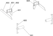
On the basis of embodiment 1, as shown in fig. 7, 8 and 9, the clamping device further includes a clamping assembly 5, the clamping assembly 5 includes a supporting block 501, a clamping rod 502 and a sixth spring 503, the supporting blocks 501 are respectively disposed on the left and right sides of the outside of the first supporting rod 204, the clamping rods 502 are respectively slidably disposed on the inner sides of the supporting blocks 501, circular holes are symmetrically formed in the first rotating shaft 301, the clamping rods 502 are respectively matched with the circular holes, the sixth springs 503 are respectively connected between the clamping rods 502 and the supporting blocks 501, and the sixth springs 503 are respectively sleeved on the clamping rods 502.
Under initial state, card pole 502 can cooperate with the round hole on the first rotation axis 301, when first rotation axis 301 rotates, round hole on the first rotation axis 301 can break away from with card pole 502, card pole 502 can move to the outside, sixth spring 503 is compressed, when first rotation axis 301 rotates one hundred eighty degrees, the round hole can continue to cooperate with card pole 502, because sixth spring 503's reset action, can drive card pole 502 and move to the inside, thereby continue to block first rotation axis 301, make the pivoted position more accurate at every turn, the heated board can not deflect because inertial effect takes place.
The pressing component 6 comprises a second support rod 601, a top rod 602, a second wedge-shaped block 603, a seventh spring 604 and a second sliding rod 605, the second support rod 601 is arranged at the top of the third support groove block 401, the top rod 602 is arranged at the top of the second support rod 601 in a sliding mode, the second wedge-shaped block 603 is arranged at the outer side of the bottom of the top rod 602, two seventh springs 604 are connected between the top rod 602 and the second support rod 601 on the same side, the seventh springs 604 are respectively sleeved on the second support rod 601, the second sliding rod 605 is arranged at the outer side of the first rotating shaft 301, and the second sliding rod 605 on the same side is respectively matched with the second wedge-shaped block 603.
When the first rotating shaft 301 moves left and right, the second sliding rod 605 is driven to move left and right, when the second sliding rod 605 contacts with the second wedge-shaped block 603, the second wedge-shaped block 603 is driven to move downwards, the second wedge-shaped block 603 drives the ejector rod 602 to move downwards, the seventh spring 604 is compressed, the ejector rod 602 drives the sliding block 402 to automatically move downwards, so that people do not need to manually move the sliding block 402, the efficiency of people is improved, when the second sliding rod 605 is separated from the second wedge-shaped block 603, the ejector rod 602 and the sliding block 402 are driven to move upwards to reset due to the reset effect of the seventh spring 604.
Also comprises a driving component 7, the driving component 7 comprises a third supporting rod 701, an air cylinder 702, a second rack 703 and a fourth supporting rod 704, second rotation axis 705, second gear 706, reel 707, pulley 708 and stay cord 709, bilateral symmetry is equipped with third bracing piece 701 between the wedge pole 208 downside, be equipped with cylinder 702 between the third bracing piece 701 downside, be equipped with second rack 703 on the telescopic link of cylinder 702, wedge pole 208 left side middle part all is equipped with fourth bracing piece 704, the rotary type is equipped with second rotation axis 705 between the fourth bracing piece 704 downside, second rotation axis 705 middle part is equipped with second gear 706, intermeshing between second gear 706 and the second rack 703, second rotation axis 705 front and back both sides are equipped with reel 707, wedge pole 208 upside all is equipped with pulley 708 in the rotary type, homonymy reel 707 all is connected with stay cord 709 respectively between through pulley 708 and the first bracing piece 204.
People start the air cylinder 702, the telescopic rod of the air cylinder 702 can drive the second rack 703 to move left and right, when the second rack 703 moves to the left, the second gear 706 can be driven to rotate in the forward direction, the second gear 706 can drive the second rotating shaft 705 and the reel 707 to rotate in the forward direction, the reel 707 can drive the pull rope 709 to move to the left through the pulley 708, the right end of the pull rope 709 can drive the first supporting rod 204 to move to the left, thereby automatically driving the placing plate 205 to move to the left, so that people can operate more conveniently, when the second rack 703 moves to the right, the second gear 706 can be driven to rotate in the reverse direction, the second rotating shaft 705 and the reel 707 can be driven to rotate in the reverse direction by the second gear 706, and due to the resetting effect of the first spring 203, the first supporting rod 204 and the pull rope 709 can be driven to.
It should be understood that this example is only for illustrating the present invention and is not intended to limit the scope of the present invention. Further, it should be understood that various changes or modifications of the present invention may be made by those skilled in the art after reading the teaching of the present invention, and such equivalents may fall within the scope of the present invention as defined in the appended claims.
Claims (8)
1. The utility model provides a face cleaning device is used in production of polyurethane heated board of customizable cutting, characterized by: comprises the following steps:
two support frames (1), wherein the number of the support frames (1) is two;
the placing component (2) is arranged between the tops of the supporting frames (1);
the middle part of the placing component (2) is provided with the overturning component (3);
the upper part of the placing component (2) is provided with a cleaning component (4).
2. The board surface cleaning device for producing the customizable and cut polyurethane insulation board according to claim 1 is characterized in that: the placing component (2) comprises:
the top of the support frame (1) is symmetrically provided with two sliding groove rods (201);
the bearings (202) are arranged between one sides of the sliding groove rods (201) on the same side in a sliding mode;
the first spring (203) is connected between the other side of the bearing (202) on the same side and the chute rod (201);
the two sides of the bearing (202) are provided with the first supporting rods (204);
the placing plate (205) is arranged between the upper parts of the first supporting rods (204) in a sliding manner;
the second springs (206) are connected between the placing plate (205) and the first supporting rods (204), and the second springs (206) are respectively sleeved on the first supporting rods (204);
the rollers (207) are rotatably arranged on two sides of the bottom of the placing plate (205);
the wedge-shaped rods (208) are arranged on one sides of the bottoms of the lower side sliding groove rods (201), and the wedge-shaped rods (208) on the same side are matched with the rollers (207) respectively.
3. The board surface cleaning device for producing the customizable and cut polyurethane insulation board as claimed in claim 2, is characterized in that: the overturning component (3) comprises:
the first rotating shaft (301), the bearings (202) are all rotatably provided with the first rotating shaft (301);
the inner sides of the first rotating shafts (301) are provided with first sliding rods (302) in a sliding manner;
the inner sides of the first sliding rods (302) are provided with clamping plates (303);
the third springs (304) are connected between the first sliding rod (302) and the first rotating shaft (301) on the same side;
the first wedge-shaped block (305) is arranged on each of two sides of the clamping plate (303);
the stop rods (306) are arranged on one sides of the lower sliding groove rods (201), and the first wedge blocks (305) on the same side are matched with the stop rods (306) respectively;
the outer sides of the first rotating shafts (301) are provided with ratchet gears (307);
the outer sides of one part of the lower sliding groove rod (201) are provided with a second supporting groove block (308);
the ratchet bars (309) are arranged on the upper sides of the second supporting groove blocks (308) in a sliding mode, and the ratchet bars (309) on the same side are matched with the ratchet wheel (307);
and a plurality of fourth springs (310) are arranged between the ratchet bar (309) on the same side and the second supporting groove block (308).
4. The board surface cleaning device for producing the customizable and cut polyurethane insulation board as claimed in claim 3, is characterized in that: the cleaning component (4) comprises:
the inner sides of the middle parts of the upper sliding groove rods (201) are provided with third supporting groove blocks (401);
the sliding blocks (402) are arranged on the third supporting groove blocks (401) in a sliding mode;
the fifth spring (403) is connected between the slider (402) on the same side and the third supporting groove block (401);
the cleaning brushes (404) are rotatably arranged between the sliding blocks (402);
the cleaning brush is characterized by comprising a first gear (405), wherein the first gear (405) is arranged on two sides of the cleaning brush (404);
the first rack (406) is arranged between the tops of the first supporting rods (204) on the two sides of the first rack (406), and the first rack (406) on the same side is meshed with the first gear (405).
5. The board surface cleaning device for producing the customizable and cut polyurethane insulation board according to claim 4 is characterized in that: still including chucking subassembly (5), chucking subassembly (5) including:
the supporting blocks (501) are arranged on two sides of the outer part of the first supporting rod (204);
the inner sides of the supporting blocks (501) are provided with clamping rods (502) in a sliding mode, round holes are symmetrically formed in the first rotating shaft (301), and the clamping rods (502) are matched with the round holes respectively;
and a sixth spring (503) is connected between the clamping rod (502) and the supporting block (501), and the sixth spring (503) is respectively sleeved on the clamping rod (502).
6. The board surface cleaning device for producing the customizable and cut polyurethane insulation board according to claim 5 is characterized in that: still including pushing down subassembly (6), push down subassembly (6) including:
the second support rods (601) are arranged at the tops of the second support rod (601) and the third support groove block (401);
the top of the top rod (602) and the top of the second support rod (601) are both provided with the top rod (602) in a sliding manner;
the outer sides of the bottoms of the ejector rods (602) are provided with second wedge-shaped blocks (603);
two seventh springs (604) are connected between the ejector rod (602) on the same side and the second supporting rod (601), and the seventh springs (604) are respectively sleeved on the second supporting rod (601);
and the outer sides of the first rotating shafts (301) of the second slide bars (605) are respectively provided with the second slide bars (605), and the second slide bars (605) on the same side are respectively matched with the second wedge-shaped blocks (603).
7. The board surface cleaning device for producing the customizable and cut polyurethane insulation board according to claim 6, is characterized in that: still including drive assembly (7), drive assembly (7) including:
a third support rod (701), wherein the third support rod (701) is symmetrically arranged between the lower sides of the wedge-shaped rods (208);
the air cylinder (702) is arranged between the lower sides of the third support rods (701);
a second rack (703) is arranged on the telescopic rod of the air cylinder (702);
the middle part of one side of each wedge-shaped rod (208) is provided with a fourth supporting rod (704);
a second rotating shaft (705), wherein the second rotating shaft (705) is rotatably arranged between the lower sides of the fourth supporting rods (704);
the middle part of the second rotating shaft (705) is provided with a second gear (706), and the second gear (706) is meshed with the second rack (703);
a reel (707), wherein the reel (707) is arranged on both sides of the second rotating shaft (705);
the pulleys (708) are rotatably arranged on the upper sides of the wedge-shaped rods (208);
and the pull ropes (709) are connected to the same-side reel (707) through the pulleys (708) and the first supporting rods (204).
8. The board surface cleaning device for producing the customizable and cut polyurethane insulation board according to claim 4 is characterized in that: the cleaning brush (404) is removable.
Priority Applications (1)
| Application Number | Priority Date | Filing Date | Title |
|---|---|---|---|
| CN202110152765.7A CN112642767A (en) | 2021-02-04 | 2021-02-04 | Board cleaning device is used in production of polyurethane heated board of customizable cutting |
Applications Claiming Priority (1)
| Application Number | Priority Date | Filing Date | Title |
|---|---|---|---|
| CN202110152765.7A CN112642767A (en) | 2021-02-04 | 2021-02-04 | Board cleaning device is used in production of polyurethane heated board of customizable cutting |
Publications (1)
| Publication Number | Publication Date |
|---|---|
| CN112642767A true CN112642767A (en) | 2021-04-13 |
Family
ID=75371049
Family Applications (1)
| Application Number | Title | Priority Date | Filing Date |
|---|---|---|---|
| CN202110152765.7A Withdrawn CN112642767A (en) | 2021-02-04 | 2021-02-04 | Board cleaning device is used in production of polyurethane heated board of customizable cutting |
Country Status (1)
| Country | Link |
|---|---|
| CN (1) | CN112642767A (en) |
Cited By (4)
| Publication number | Priority date | Publication date | Assignee | Title |
|---|---|---|---|---|
| CN113618446A (en) * | 2021-08-09 | 2021-11-09 | 陶辉 | Numerical control machine tool fixture capable of separating waste materials and water and collecting waste materials and water |
| CN113843845A (en) * | 2021-09-28 | 2021-12-28 | 湖南会当智能科技有限公司 | Novel automatic intelligent food slicer |
| CN114029261A (en) * | 2021-12-06 | 2022-02-11 | 江西视显高科技有限公司 | Surface layer cleaning device for touch screen functional sheet |
| CN114603197A (en) * | 2022-03-01 | 2022-06-10 | 金天富 | Cutting device and cutting method for aluminum plate for architectural decoration |
Citations (5)
| Publication number | Priority date | Publication date | Assignee | Title |
|---|---|---|---|---|
| AT510415A4 (en) * | 2010-12-09 | 2012-04-15 | Progress Maschinen & Automation Ag | CLEANING DEVICE FOR PALLET SHAPES |
| CN107825253A (en) * | 2017-11-30 | 2018-03-23 | 广东仕博精工科技有限公司 | A kind of glass grinding cleaning device |
| CN110615606A (en) * | 2019-10-15 | 2019-12-27 | 苏州威创达智能设备有限公司 | Automatic device that pulls after glass-cutting |
| CN112139127A (en) * | 2020-10-26 | 2020-12-29 | 广州爱邦建筑科技有限公司 | Effective deashing cleaning equipment of high performance integrated circuit board |
| CN112158574A (en) * | 2020-11-13 | 2021-01-01 | 深圳市骏欣铝基板有限公司 | Two-sided tipping arrangement is used in processing of single double-sided circuit board |
-
2021
- 2021-02-04 CN CN202110152765.7A patent/CN112642767A/en not_active Withdrawn
Patent Citations (5)
| Publication number | Priority date | Publication date | Assignee | Title |
|---|---|---|---|---|
| AT510415A4 (en) * | 2010-12-09 | 2012-04-15 | Progress Maschinen & Automation Ag | CLEANING DEVICE FOR PALLET SHAPES |
| CN107825253A (en) * | 2017-11-30 | 2018-03-23 | 广东仕博精工科技有限公司 | A kind of glass grinding cleaning device |
| CN110615606A (en) * | 2019-10-15 | 2019-12-27 | 苏州威创达智能设备有限公司 | Automatic device that pulls after glass-cutting |
| CN112139127A (en) * | 2020-10-26 | 2020-12-29 | 广州爱邦建筑科技有限公司 | Effective deashing cleaning equipment of high performance integrated circuit board |
| CN112158574A (en) * | 2020-11-13 | 2021-01-01 | 深圳市骏欣铝基板有限公司 | Two-sided tipping arrangement is used in processing of single double-sided circuit board |
Cited By (6)
| Publication number | Priority date | Publication date | Assignee | Title |
|---|---|---|---|---|
| CN113618446A (en) * | 2021-08-09 | 2021-11-09 | 陶辉 | Numerical control machine tool fixture capable of separating waste materials and water and collecting waste materials and water |
| CN113618446B (en) * | 2021-08-09 | 2023-12-29 | 陶辉 | Numerical control machine tool fixture capable of separating and collecting waste and water |
| CN113843845A (en) * | 2021-09-28 | 2021-12-28 | 湖南会当智能科技有限公司 | Novel automatic intelligent food slicer |
| CN114029261A (en) * | 2021-12-06 | 2022-02-11 | 江西视显高科技有限公司 | Surface layer cleaning device for touch screen functional sheet |
| CN114603197A (en) * | 2022-03-01 | 2022-06-10 | 金天富 | Cutting device and cutting method for aluminum plate for architectural decoration |
| CN114603197B (en) * | 2022-03-01 | 2024-04-09 | 吉祥新材料股份有限公司 | Cutting device and cutting method for aluminum plate for building decoration |
Similar Documents
| Publication | Publication Date | Title |
|---|---|---|
| CN112642767A (en) | Board cleaning device is used in production of polyurethane heated board of customizable cutting | |
| CN112476648A (en) | Automatic cutting machine for wood bar stripes | |
| CN112549107A (en) | Department of traditional chinese medicine is with can be fast to abluent energy-concerving and environment-protective device of medicinal material section | |
| CN112475430B (en) | Steel cutting equipment for water works construction | |
| CN116833592B (en) | Laser cutting device for car callus on sole | |
| CN113662024A (en) | Food mold surface brushing equipment | |
| CN101496710A (en) | Mop dewatering equipment | |
| CN216123810U (en) | Skin remove device is used in dendrobii officmalis caulis production | |
| CN114311184B (en) | Industry square wood burnishing device | |
| CN201370554Y (en) | Self-help type dewatering device | |
| CN210386673U (en) | Two-sided cleaning device of timber | |
| CN112683637A (en) | Clinical examination is with pathological section former | |
| CN112515194A (en) | Convenient persimmon equipment of peeling | |
| CN114455823A (en) | Industry laser cuts circular glass device | |
| CN108113599B (en) | Dual-purpose mop for mopping and sweeping floor | |
| CN113319038A (en) | Industrial part self-cleaning device | |
| CN215660774U (en) | Circular stick preparation equipment | |
| CN220631385U (en) | Water squeezing device of cleaning brush | |
| CN111700554B (en) | Cleaning plastic cleaning ball poking device | |
| CN219599620U (en) | Pickled food processing and slicing device | |
| CN212437111U (en) | Tangent plane tail face automatic collection device | |
| CN218779214U (en) | Cutting device for processing polyester silk fabric | |
| CN216543547U (en) | Circular glass cutting former | |
| CN215100271U (en) | Zipper machine with dust removal device | |
| CN113716319B (en) | Uropoiesis is urine examination container recovery unit for surgery |
Legal Events
| Date | Code | Title | Description |
|---|---|---|---|
| PB01 | Publication | ||
| PB01 | Publication | ||
| SE01 | Entry into force of request for substantive examination | ||
| SE01 | Entry into force of request for substantive examination | ||
| WW01 | Invention patent application withdrawn after publication |
Application publication date: 20210413 |
|
| WW01 | Invention patent application withdrawn after publication |