EP2462819A2 - Regulation assembly for a cigarette manufacturing machine and method for regulating the transport of the cigarette filler - Google Patents
Regulation assembly for a cigarette manufacturing machine and method for regulating the transport of the cigarette filler Download PDFInfo
- Publication number
- EP2462819A2 EP2462819A2 EP20110009086 EP11009086A EP2462819A2 EP 2462819 A2 EP2462819 A2 EP 2462819A2 EP 20110009086 EP20110009086 EP 20110009086 EP 11009086 A EP11009086 A EP 11009086A EP 2462819 A2 EP2462819 A2 EP 2462819A2
- Authority
- EP
- European Patent Office
- Prior art keywords
- air
- control arrangement
- flow
- cigarette
- conveying
- Prior art date
- Legal status (The legal status is an assumption and is not a legal conclusion. Google has not performed a legal analysis and makes no representation as to the accuracy of the status listed.)
- Granted
Links
- 235000019504 cigarettes Nutrition 0.000 title claims abstract description 68
- 239000000945 filler Substances 0.000 title claims abstract description 41
- 238000004519 manufacturing process Methods 0.000 title claims abstract description 22
- 238000000034 method Methods 0.000 title claims abstract description 20
- 230000001105 regulatory effect Effects 0.000 title abstract description 8
- 230000033228 biological regulation Effects 0.000 title description 5
- 241000208125 Nicotiana Species 0.000 claims abstract description 10
- 235000002637 Nicotiana tabacum Nutrition 0.000 claims abstract description 10
- 230000032258 transport Effects 0.000 claims abstract description 8
- 238000009423 ventilation Methods 0.000 claims abstract description 5
- 235000019505 tobacco product Nutrition 0.000 claims abstract description 4
- 239000012530 fluid Substances 0.000 claims description 23
- 238000000605 extraction Methods 0.000 claims 2
- 230000001276 controlling effect Effects 0.000 abstract description 4
- 239000002245 particle Substances 0.000 description 7
- 238000005259 measurement Methods 0.000 description 5
- 238000009530 blood pressure measurement Methods 0.000 description 3
- 230000006835 compression Effects 0.000 description 2
- 238000007906 compression Methods 0.000 description 2
- 230000001419 dependent effect Effects 0.000 description 2
- 238000009434 installation Methods 0.000 description 2
- 230000002411 adverse Effects 0.000 description 1
- 238000011161 development Methods 0.000 description 1
- 238000006073 displacement reaction Methods 0.000 description 1
- 230000000694 effects Effects 0.000 description 1
- 239000008141 laxative Substances 0.000 description 1
- 230000002475 laxative effect Effects 0.000 description 1
- 238000012423 maintenance Methods 0.000 description 1
- 239000011148 porous material Substances 0.000 description 1
- 238000012545 processing Methods 0.000 description 1
- 238000007634 remodeling Methods 0.000 description 1
- 238000009420 retrofitting Methods 0.000 description 1
- 239000000126 substance Substances 0.000 description 1
Images

Classifications
-
- A—HUMAN NECESSITIES
- A24—TOBACCO; CIGARS; CIGARETTES; SIMULATED SMOKING DEVICES; SMOKERS' REQUISITES
- A24C—MACHINES FOR MAKING CIGARS OR CIGARETTES
- A24C5/00—Making cigarettes; Making tipping materials for, or attaching filters or mouthpieces to, cigars or cigarettes
- A24C5/14—Machines of the continuous-rod type
- A24C5/18—Forming the rod
- A24C5/1871—Devices for regulating the tobacco quantity
Definitions
- the invention relates to a control arrangement for a cigarette manufacturing machine according to the preamble of claim 1 and to a method for controlling the transport of the cigarette filler in a cigarette manufacturing machine according to the preamble of claim 7.
- the cigarette filler which is usually tobacco or a tobacco product, transported by a conveying medium, which is usually designed as a circulating belt.
- the cigarette filler is formed into a strand from which the cigarettes are produced in the further process.
- the fluid is carried out permeable to air, so that an air flow can pass through the fluid.
- This makes it possible to supply the cigarette filler in an air flow to the conveying medium, wherein the cigarette filler is pressed by the passing through the conveying medium air flow to the conveying medium.
- This results in a relationship between the properties of the strand of cigarette filler, which is formed on the fluid and the prevailing flow conditions, in particular the passage speed of the air through the fluid.
- the contact pressure of the cigarette filler depends to the fluid from.
- the contact pressure results from the specific resistance coefficient (CW value) of the cigarette filler and its flow around.
- CW value specific resistance coefficient
- the compression force of the cigarette filler and the resulting amount of filler per cigarette and its homogeneity depend on the contact force.
- the fluid usually a wear that occurs within a few hours of operation is subject, with its flow resistance to the passing air flow due to the finest tobacco particles that are stored in the fluid changes.
- the tobacco contains the finest but abrasive substances that pass through the air flow through the pumped medium and are responsible for wear of the compressor, which is also worn after a few months and loses efficiency in the course of this wear development.
- the pressure loss during the passage of the air through the pumped medium is generally between about 80 and 140 mbar.
- compressors which are turbomachines.
- This type of compressor is characterized by a dependent on the pressure difference to be overcome flow. Accordingly, the entire system is sensitive to variations in pressure loss during the passage of air through the fluid.
- this method is suitable for compensating for cigarette filler density variations, it does not solve the problem of changes in the flow characteristics of the fluid in service, it may even aggravate it, since changes in the characteristics of the fluid, such as changes in cigarette filler properties, affect the control and so on lead to an adverse unwanted influence on the cigarette filler flow.
- the invention is therefore based on the object to provide a control arrangement and a method for controlling the cigarette filler transport, which allow the production of a cigarette filler strand with continuously consistent quality.
- control arrangement comprises a flow control for the passing through the fluid flow of air, which transports the cigarette filler to the fluid.
- the flow rate is controlled, the per unit time, the fluid passing through the amount of air and thus the suction rate remains constant, regardless of which absolute pressure Any location of the pneumatic system of the cigarette making machine prevails.
- the control arrangement may have a measuring device for measuring the mass flow and / or volume flow.
- Both the Massenals and the flow rate are suitable in principle as a suitable size for measuring or regulating the flow rate, the air passing through the medium.
- the mass flow offers the advantage of being directly proportional to the mass flow, ie the amount of air molecules delivered per unit time, and thus of being independent of pressure and temperature influences.
- the volume flow in the present case is also suitable as measured and / or controlled variable, since the fluctuations which pressure and temperature in the case of the present process are subject to in the region of the measuring point are so small that the density change of the air and thus the pressure and temperature influence can be neglected on the dependence of the volume flow of the flow.
- the measurement of the mass and / or volumetric flow can preferably take place by means of a differential pressure measurement, which is based on the calculation of the mass / volumetric flow as a function of a pressure difference.
- the differential pressure measurement can be carried out, for example, on a metering orifice or another similar component located in the airflow or on a tapering of the line carrying the airflow, brought about by suitable installations.
- This type of measurement has the advantage of high reliability, especially in the present, usually loaded with abrasive particles, air flow.
- the measurement can also be carried out by other methods, in particular taking advantage of the measurement of the heat flow of an electrically heated wire or the measurement of the pressure build-up in front of an impeller or a damper blade or similar internals.
- the air conveying device which promotes the passing through the medium conveyed air, connected to the input of an exhaust system.
- an exhaust system all types of process air laxative systems are initially meant, this may for example be a simple hall ventilation, but it can also be a complex process air treatment plant, which may have, for example, filter devices provided.
- Such an exhaust system serve to remove the finest particles of the cigarette filler, which are transported by the air flow passing through the conveying medium through the conveying medium, from the process air stream.
- the air flow which first transports the cigarette filler to the pumped medium, then passes through this and transported by the conveyor, which may still be located in the cigarette manufacturing machine, to the exhaust outlet or optionally to an exhaust system is, in stationary operation at any point of the air flow guide, at least as long as it still has no branches, is constant, it is in principle possible to provide the control arrangement, in particular their measuring device at each point of this air flow guide.
- the control arrangement, in particular its measuring device is preferably arranged in the region of an air flow conveyed from the air conveying device to the exhaust air system. This is particularly advantageous if the air conveying device is provided inside the cigarette manufacturing machine.
- control arrangement and cigarette manufacturing machine are spatially separated simplifies an upgrade or retrofitting as well as maintenance, installation and remodeling considerably.
- Such a continuity of the air flow rate is given in each case for the air flow rate, which actually passes through the fluid in the conveying direction to the first branch, with any supply air currents that may occur, for example, through leaks in the system, so far not disturbing in continuous operation, since an exact knowledge of the air flow rate is not absolutely necessary.
- the only important thing is to keep it constant at a level optimized for cigarette production. So it is not necessary that the amount of air flow constantly controlled, for example, between the air conveyor and the entrance to the exhaust system actually corresponds exactly quantitatively exactly to the flow of air passing through the fluid. It is only important that the controlled flow rate and the mass flow actually passing through the fluid are quantitatively dependent on each other.
- the control arrangement preferably has a controlled throttle device, for example a throttle flap, as an actuator.
- a controlled throttle device has the advantage that it represents a cost-effective and reliable way of controlling the amount of air passage and makes it possible not to change the air delivery device, which may be a compressor, for example in a retrofitted control arrangement.
- the air delivery device which may be a compressor, for example in a retrofitted control arrangement.
- An intended exhaust air system preferably has a vacuum generating device.
- This vacuum generating device is preferably arranged behind a central filter unit, ie it is no longer subject to wear by promoted with the air flow finest cigarette filler particles and can thus provide additional air flow capacity. This is particularly useful if the performance of the air conveyor due to their wear by the finest cigarette filler particles declining. This loss of performance can then be compensated for by using the negative pressure provided by the central exhaust air system in order to relieve the air delivery device.
- negative pressure is meant that the absolute pressure of the negative pressure is lower than the absolute pressure of the air before passing through the fluid.
- volumetric air conveyor Another possibility for realizing the volume flow control according to the invention is the use of a volumetric air conveyor.
- Such conveyors such as positive displacement blower or reciprocating compressors, are characterized in that the delivered volume flow depends directly on the speed of the air conveyor. Due to the sufficiently exact correlation in the present case between volume and mass or mass flow, a control according to the invention of the mass flow can already be realized by the use of a volumetric air conveyor, which, for example, by setting and / or regulating a constant speed on the Promotion of a constant flow rate is set or regulated.
- volumetric air conveying devices in particular volumetric compressors
- turbomachinery which are normally used in the boundary conditions, as prevail in the present case (low pressure loss in the conveyor line)
- turbomachinery which are normally used in the boundary conditions, as prevail in the present case (low pressure loss in the conveyor line)
- turbomachinery are used to an increase in react to be overcome pressure difference with a decrease in the delivered volume flow
- the use of forced-conveying volumetric air conveyors the flow and thus in the present case with sufficient accuracy of the mass / flow rate, constant.
- the exemplary control arrangement according to the invention has a controlled throttle device 5 and a measuring device 4 for measuring the flow rate of the air conveyor 3, which is integrated in the cigarette manufacturing machine 8 in the example shown, to the input 6 of an exhaust air system funded.
- the exhaust air system 7 shown by way of example here has a vacuum generating device 11 and a filter device 10 and has a plurality of inputs 6, so that a plurality of cigarette manufacturing machines 8 can be connected to control systems according to the invention to a common exhaust system 7.
- the cigarette filler 9 is supplied to the conveying medium 2 by a feed device 1.
- Specific intake rates and flow conditions are set in the area of the feed device 1, depending on the amount of air flow passing through the pumped medium 2, which must be optimized for each cigarette filler, in particular for each type of tobacco, in order to achieve optimum properties of the tobacco rod formed on the pumped medium 2 ,
- the conveying medium 2 is oriented in such a way that due to the air flow passing through the conveying medium, the cigarette filler is pressed against the underside of the conveying medium 2 against the surface of the conveying medium 2.
- the air flow rate passing through the conveying medium 2 is then conveyed out of the cigarette manufacturing machine 8 by the air conveying device 3, the air flow rate of this air conveyed out of the cigarette manufacturing machine 8 being regulated by the regulating arrangement according to the invention in the example shown.
- the throttle device 5 of the exemplary control arrangement of the air flow reaches the entrance 6 of the exhaust system 7, wherein the input 6 is designed to connect a plurality of Switzerlandarettenher einsmaschinen 8 to the exhaust system 7, if necessary.
- the exhaust air system 7 has a filter device 10, which filters out the finest cigarette filler particles from the exhaust air of the cigarette manufacturing machines, and a vacuum generating device 11 which is adapted to generate a negative pressure, which can be used to relieve the air conveyor 3 of the cigarette manufacturing machine 8.
- FIG. 2 an alternative embodiment is shown, in which a volumetric air conveyor 3 is used to implement the control according to the invention.
- the regulation takes place here by utilizing the delivery characteristics of the volumetric air conveyor 3, in which the speed of the drive 12 is kept constant.
Abstract
Description
Die Erfindung betrifft eine Regelungsanordnung für eine Zigarettenherstellungsmaschine nach dem Oberbegriff des Anspruchs 1 sowie ein Verfahren zur Regelung des Transports des Zigarettenfüllstoffs in einer Zigarettenherstellungsmaschine nach dem Oberbegriff des Anspruchs 7.The invention relates to a control arrangement for a cigarette manufacturing machine according to the preamble of claim 1 and to a method for controlling the transport of the cigarette filler in a cigarette manufacturing machine according to the preamble of
Bei Zigarettenherstellungsmaschinen der in Rede stehenden Art wird der Zigarettenfüllstoff, bei dem es sich meistens um Tabak oder ein Tabakerzeugnis handelt, von einem Fördermedium, welches in der Regel als umlaufendes Band ausgeführt ist, transportiert. Dabei wird der Zigarettenfüllstoff zu einem Strang geformt, aus dem im weiteren Prozess die Zigaretten hergestellt werden.In cigarette manufacturing machines of the type in question is the cigarette filler, which is usually tobacco or a tobacco product, transported by a conveying medium, which is usually designed as a circulating belt. The cigarette filler is formed into a strand from which the cigarettes are produced in the further process.
Das Fördermedium ist dabei luftdurchlässig ausgeführt, so dass ein Luftstrom durch das Fördermedium durchtreten kann. Dies ermöglicht es, den Zigarettenfüllstoff in einem Luftstrom dem Fördermedium zuzuführen, wobei der Zigarettenfüllstoff durch den durch das Fördermedium durchtretenden Luftstrom an das Fördermedium angedrückt wird. Dabei ergibt sich ein Zusammenhang aus den Eigenschaften des Strangs aus Zigarettenfüllstoff, der an dem Fördermedium gebildet wird und den herrschenden Strömungsverhältnissen, insbesondere der Durchtrittsgeschwindigkeit der Luft durch das Fördermedium.The fluid is carried out permeable to air, so that an air flow can pass through the fluid. This makes it possible to supply the cigarette filler in an air flow to the conveying medium, wherein the cigarette filler is pressed by the passing through the conveying medium air flow to the conveying medium. This results in a relationship between the properties of the strand of cigarette filler, which is formed on the fluid and the prevailing flow conditions, in particular the passage speed of the air through the fluid.
Von den Strömungsverhältnissen, die sich unmittelbar vor dem Eintritt der Luft in das Fördermedium einstellen, hängt insbesondere die Anpresskraft des Zigarettenfüllstoffs an das Fördermedium ab. Die Anpresskraft ergibt sich dabei aus dem spezifischen Widerstandsbeiwert (CW-Wert) des Zigarettenfüllstoffs und dessen Umströmung. Von der Anpresskraft wiederum abhängig ist die Verdichtung des Zigarettenfüllstoffs und die sich daraus ergebende Füllstoffmenge pro Zigarette, und deren Homogenität.Of the flow conditions that are set immediately before the entry of air into the fluid, in particular the contact pressure of the cigarette filler depends to the fluid from. The contact pressure results from the specific resistance coefficient (CW value) of the cigarette filler and its flow around. In turn, the compression force of the cigarette filler and the resulting amount of filler per cigarette and its homogeneity depend on the contact force.
Aufgrund der hohen Verarbeitungsgeschwindigkeiten und Qualitätsanforderungen an Zigaretten ist es daher wichtig, den Luftstrom und damit den Tabaktransport bei möglichst unveränderten Prozessparametern durchzuführen. Problematisch hierbei ist jedoch, dass zum Einen das Fördermedium in der Regel einem Verschleiß, der innerhalb weniger Betriebsstunden eintritt, unterliegt, wobei sich dessen Strömungswiderstand gegenüber dem durchtretenden Luftstrom aufgrund feinster Tabakpartikel, die sich in dem Fördermedium einlagern, ändert. Des Weiteren enthält der Tabak feinste aber abrasive Stoffe, die mit dem Luftstrom durch das Fördermedium durchtreten und für einen Verschleiß des Verdichters verantwortlich sind, der ebenfalls nach wenigen Monaten verschlissen ist und im Laufe dieser Verschleißentwicklung an Wirkungsgrad einbüßt.Due to the high processing speeds and quality requirements of cigarettes, it is therefore important to carry out the air flow and thus the tobacco transport with unchanged process parameters. The problem here, however, is that on the one hand the fluid usually a wear that occurs within a few hours of operation is subject, with its flow resistance to the passing air flow due to the finest tobacco particles that are stored in the fluid changes. Furthermore, the tobacco contains the finest but abrasive substances that pass through the air flow through the pumped medium and are responsible for wear of the compressor, which is also worn after a few months and loses efficiency in the course of this wear development.
Der Druckverlust beim Durchtritt der Luft durch das Fördermedium beträgt in der Regel Werte zwischen ca. 80 und 140 mbar. Zur Förderung der Luft kommen daher Verdichter zum Einsatz, bei denen es sich um Strömungsmaschinen handelt. Diese Art Verdichter zeichnet sich durch einen von der zu überwindenden Druckdifferenz abhängigen Volumenstrom aus. Dementsprechend empfindlich reagiert das gesamte System auf Schwankungen des Druckverlusts beim Durchtritt der Luft durch das Fördermedium.The pressure loss during the passage of the air through the pumped medium is generally between about 80 and 140 mbar. For the promotion of air therefore compressors are used, which are turbomachines. This type of compressor is characterized by a dependent on the pressure difference to be overcome flow. Accordingly, the entire system is sensitive to variations in pressure loss during the passage of air through the fluid.
Aus dem Stand der Technik ist bekannt, eine manuell betätigte Drosselklappe vorzusehen, mit der es möglich ist, diesen Druckverlust nachzuregeln. Es ist auch bekannt, eine Druckmessung der Luft nach Durchtritt durch das Saugband durchzuführen und diesen gemessenen Druck durch das Vorsehen einer Regelung, welche beispielsweise auf eine steuerbare Drosseleinrichtung oder den Antrieb des Verdichters wirkt, konstant zu halten.From the prior art is known to provide a manually operated throttle, with which it is possible to readjust this pressure loss. It is also known to carry out a pressure measurement of the air after passing through the suction belt and to keep this measured pressure constant by providing a control which acts, for example, on a controllable throttle device or the drive of the compressor.
Derartige Regelungen können jedoch nicht verhindern, dass aufgrund von Veränderungen der Durchströmungseigenschaften des Fördermediums Schwankungen der geförderten Luftmenge und damit der Strömungsverhältnisse am Saugband und der Eigenschaften des geförderten Zigarettenfüllstoffstrangs auftreten.However, such regulations can not prevent that due to changes in the flow characteristics of the pumped medium fluctuations in the amount of air delivered and thus the flow conditions on the suction belt and the properties of the promoted cigarette filler strand occur.
Weiterhin ist aus der
Der Erfindung liegt daher die Aufgabe zugrunde, eine Regelungsanordnung und ein Verfahren zur Regelung des Zigarettenfüllstofftransports anzugeben, welche die Produktion eines Zigarettenfüllstoffstrangs mit kontinuierlich gleichbleibender Qualität ermöglichen.The invention is therefore based on the object to provide a control arrangement and a method for controlling the cigarette filler transport, which allow the production of a cigarette filler strand with continuously consistent quality.
Gelöst wird die Aufgabe durch eine Regelungsanordnung mit den Merkmalen des Anspruchs 1 sowie durch ein Verfahren mit den Merkmalen des Anspruchs 7. Die Merkmale der Unteransprüche betreffen vorteilhafte Ausführungsformen.The object is achieved by a control arrangement having the features of claim 1 and by a method having the features of
Erfindungsgemäß wird die Aufgabe dadurch gelöst, dass die Regelungsanordnung eine Mengenstromregelung für den durch das Fördermedium durchtretenden Luftstrom, der den Zigarettenfüllstoff zum Fördermedium transportiert, aufweist. Dadurch, dass der Mengenstrom geregelt wird, bleibt die pro Zeiteinheit das Fördermedium durchtretende Luftmenge und damit die Ansauggeschwindigkeit konstant, unabhängig davon, welcher absolute Druck an irgendeiner Stelle des pneumatischen Systems der Zigarettenherstellungsmaschine herrscht. Dadurch ist gewährleistet, dass, wenn sich im Laufe des Betriebs der Luftdurchtrittswiderstand des Fördermediums ändert, insbesondere dann, wenn sich beispielsweise Poren des luftdurchlässigen Fördermediums mit feinsten Tabakpartikeln zusetzen und damit verschlossen werden, dies keinen Einfluss auf die von der Regelungsanordnung konstant gehaltene, durch das Fördermedium durchtretende Luftmenge pro Zeiteinheit hat, d.h. die Regelung ist unabhängig von der Änderung des Druckverlustes der durch das Fördermedium durchtretenden Luft beim Durchtritt durch das Fördermedium.According to the invention the object is achieved in that the control arrangement comprises a flow control for the passing through the fluid flow of air, which transports the cigarette filler to the fluid. Characterized in that the flow rate is controlled, the per unit time, the fluid passing through the amount of air and thus the suction rate remains constant, regardless of which absolute pressure Any location of the pneumatic system of the cigarette making machine prevails. This ensures that, if changes in the course of operation of the air passage resistance of the fluid, especially if, for example, pores of the air-permeable medium enforced with the finest tobacco particles and are thus closed, this has no effect on the constant held by the control arrangement, by the Flow medium passing through the amount of air per unit of time, ie, the regulation is independent of the change in the pressure loss of the air passing through the fluid passing through the fluid.
Diese Regelung kann auf unterschiedliche Weise realisiert werden. Beispielsweise kann die Regelungsanordnung eine Messeinrichtung zur Messung des Massen- und/oder Volumenstroms aufweisen. Sowohl der Massenals auch der Volumenstrom eignen sich prinzipiell als geeignete Größe zur Messung bzw. Regelung des Mengenstroms, der durch das Fördermedium durchtretenden Luft. Dabei bietet der Massenstrom den Vorteil, direkt proportional zu dem Mengenstrom, d.h. der Menge der pro Zeiteinheit geförderten Luftmoleküle, und damit von Druck- und Temperatureinflüssen unabhängig zu sein. Der Volumenstrom eignet sich im vorliegenden Fall jedoch auch als Mess- und/oder Regelgröße, da die Schwankungen, denen Druck und Temperatur im Fall des vorliegenden Prozesses im Bereich der Messstelle unterliegen, derart gering sind, dass die Dichteänderung der Luft und damit der Druck- und Temperatureinfluss auf die Abhängigkeit des Volumenstroms vom Mengenstrom vernachlässigt werden kann.This regulation can be realized in different ways. For example, the control arrangement may have a measuring device for measuring the mass flow and / or volume flow. Both the Massenals and the flow rate are suitable in principle as a suitable size for measuring or regulating the flow rate, the air passing through the medium. The mass flow offers the advantage of being directly proportional to the mass flow, ie the amount of air molecules delivered per unit time, and thus of being independent of pressure and temperature influences. However, the volume flow in the present case is also suitable as measured and / or controlled variable, since the fluctuations which pressure and temperature in the case of the present process are subject to in the region of the measuring point are so small that the density change of the air and thus the pressure and temperature influence can be neglected on the dependence of the volume flow of the flow.
Dabei kann die Messung des Massen- und/oder Volumenstroms vorzugsweise durch eine Differenzdruckmessung, welche auf der Berechnung des Massen-/Volumenstroms als Funktion einer Druckdifferenz beruht, erfolgen. Dabei kann die Differenzdruckmessung beispielsweise an einer Messblende oder einem anderen ähnlichen im Luftstrom befindlichen Bauteil oder an einer durch geeignete Einbauten herbeigeführten Verjüngung der den Luftstrom führenden Leitung erfolgen. Diese Art der Messung hat den Vorteil hoher Zuverlässigkeit, insbesondere in dem vorliegenden, in der Regel mit abrasiven Partikeln beladenen, Luftstrom. Alternativ kann die Messung jedoch auch über andere Verfahren, insbesondere unter Ausnutzung der Messung des Wärmeabflusses eines elektrisch beheizten Drahtes oder der Messung des Druckaufbaus vor einem Flügelrad oder einem Klappenblatt oder ähnlichen Einbauten erfolgen.In this case, the measurement of the mass and / or volumetric flow can preferably take place by means of a differential pressure measurement, which is based on the calculation of the mass / volumetric flow as a function of a pressure difference. In this case, the differential pressure measurement can be carried out, for example, on a metering orifice or another similar component located in the airflow or on a tapering of the line carrying the airflow, brought about by suitable installations. This type of measurement has the advantage of high reliability, especially in the present, usually loaded with abrasive particles, air flow. Alternatively, however, the measurement can also be carried out by other methods, in particular taking advantage of the measurement of the heat flow of an electrically heated wire or the measurement of the pressure build-up in front of an impeller or a damper blade or similar internals.
Vorzugsweise ist die Luftfördereinrichtung, welche die durch das Fördermedium durchtretende Luft fördert, mit dem Eingang einer Abluftanlage verbunden. Unter Abluftanlage sind zunächst alle Arten Prozessluft abführende Anlagen gemeint, dabei kann es sich beispielsweise um eine simple Hallenentlüftung handeln, es kann aber auch eine komplexe Prozessluftaufbereitungsanlage, welche beispielsweise Filtereinrichtungen aufweisen kann, vorgesehen sein. Eine derartige Abluftanlage kann beispielsweise dazu dienen, feinste Partikel des Zigarettenfüllstoffs, die mit dem das Fördermedium durchtretenden Luftstrom durch das Fördermedium transportiert werden, aus dem Prozessluftstrom zu entfernen.Preferably, the air conveying device, which promotes the passing through the medium conveyed air, connected to the input of an exhaust system. Under exhaust system all types of process air laxative systems are initially meant, this may for example be a simple hall ventilation, but it can also be a complex process air treatment plant, which may have, for example, filter devices provided. Such an exhaust system, for example, serve to remove the finest particles of the cigarette filler, which are transported by the air flow passing through the conveying medium through the conveying medium, from the process air stream.
Da bei einer entsprechend geschlossenen Ausführung des pneumatischen Systems der Zigarettenherstellungsmaschine der Luftstrom, welcher den Zigarettenfüllstoff zunächst zum Fördermedium transportiert, dann durch dieses hindurchtritt und von der Fördereinrichtung, welche noch in der Zigarettenherstellungsmaschine angeordnet sein kann, zu deren Abluftausgang bzw. gegebenenfalls zu einer Abluftanlage transportiert wird, im stationären Betrieb an jeder Stelle der Luftstromführung, zumindest solange diese noch keine Abzweigungen aufweist, konstant ist, ist es prinzipiell möglich, die Regelungsanordnung, insbesondere deren Messeinrichtung an jeder Stelle dieser Luftstromführung vorzusehen. Vorzugsweise wird die Regelungsanordnung, insbesondere deren Messeinrichtung, dabei im Bereich eines von der Luftfördereinrichtung zur Abluftanlage geförderten Luftstroms angeordnet. Dies ist insbesondere von Vorteil, wenn die Luftfördereinrichtung innerhalb der Zigarettenherstellungsmaschine vorgesehen ist. Dass Regelungsanordnung und Zigarettenherstellungsmaschine räumlich voneinander getrennt sind, vereinfacht ein Auf- bzw. Nachrüsten sowie Wartungs-, Ein- und Umbauarbeiten erheblich. Eine derartige Kontinuität des Luftmengenstromes ist in jedem Fall für den Luftmengenstrom, der tatsächlich durch das Fördermedium durchtritt, in Förderrichtung bis zur ersten Verzweigung gegeben, wobei sich etwaige Zuluftströme, die beispielsweise durch Undichtigkeiten des Systems auftreten können, im kontinuierlichen Betrieb insofern nicht störend auswirken, da eine genaue Kenntnis des Luftmengenstroms nicht unbedingt notwendig ist. Wichtig ist lediglich, diesen auf einem für die Zigarettenherstellung optimierten Niveau konstant zu halten. Es ist also nicht notwendig, dass der beispielsweise zwischen Luftfördereinrichtung und Eingang der Abluftanlage konstant geregelte Luftmengenstrom tatsächlich absolut dem durch das Fördermedium durchtretenden Luftmengenstrom quantitativ exakt entspricht, es ist lediglich wichtig, dass der geregelte Mengenstrom und der tatsächlich durch das Fördermedium durchtretende Mengenstrom quantitativ voneinander abhängen.Since in a correspondingly closed embodiment of the pneumatic system of the cigarette manufacturing machine, the air flow, which first transports the cigarette filler to the pumped medium, then passes through this and transported by the conveyor, which may still be located in the cigarette manufacturing machine, to the exhaust outlet or optionally to an exhaust system is, in stationary operation at any point of the air flow guide, at least as long as it still has no branches, is constant, it is in principle possible to provide the control arrangement, in particular their measuring device at each point of this air flow guide. The control arrangement, in particular its measuring device, is preferably arranged in the region of an air flow conveyed from the air conveying device to the exhaust air system. This is particularly advantageous if the air conveying device is provided inside the cigarette manufacturing machine. The fact that control arrangement and cigarette manufacturing machine are spatially separated simplifies an upgrade or retrofitting as well as maintenance, installation and remodeling considerably. Such a continuity of the air flow rate is given in each case for the air flow rate, which actually passes through the fluid in the conveying direction to the first branch, with any supply air currents that may occur, for example, through leaks in the system, so far not disturbing in continuous operation, since an exact knowledge of the air flow rate is not absolutely necessary. The only important thing is to keep it constant at a level optimized for cigarette production. So it is not necessary that the amount of air flow constantly controlled, for example, between the air conveyor and the entrance to the exhaust system actually corresponds exactly quantitatively exactly to the flow of air passing through the fluid. It is only important that the controlled flow rate and the mass flow actually passing through the fluid are quantitatively dependent on each other.
Vorzugsweise weist die Regelungsanordnung eine angesteuerte Drosseleinrichtung, beispielsweise eine Drosselklappe, als Stellglied auf. Eine derartige angesteuerte Drosseleinrichtung hat den Vorteil, dass sie eine kostengünstige und zuverlässige Möglichkeit zur Regelung der Luftdurchtrittsmenge darstellt und es ermöglicht, bei der Luftfördereinrichtung, bei der es sich beispielsweise um einen Verdichter handeln kann, bei einer nachgerüsteten Regelungsanordnung nicht verändert werden muss. Alternativ ist es jedoch natürlich auch möglich, beispielsweise eine Drehzahlregelung an einem Verdichter als Stellglied der Regelungsanordnung zu verwenden.The control arrangement preferably has a controlled throttle device, for example a throttle flap, as an actuator. Such a controlled throttle device has the advantage that it represents a cost-effective and reliable way of controlling the amount of air passage and makes it possible not to change the air delivery device, which may be a compressor, for example in a retrofitted control arrangement. Alternatively, it is of course also possible to use, for example, a speed control on a compressor as an actuator of the control arrangement.
Vorzugsweise weist eine vorgesehene Abluftanlage dabei eine Unterdruckerzeugungseinrichtung auf. Diese Unterdruckerzeugungseinrichtung ist dabei vorzugsweise hinter einer zentralen Filtereinheit angeordnet, d.h. sie unterliegt nicht mehr dem Verschleiß durch mit dem Luftstrom geförderte feinste Zigarettenfüllstoffpartikel und kann damit zusätzliche Luftförderleistung bereit stellen. Dies ist insbesondere dann sinnvoll, wenn die Leistungsfähigkeit der Luftfördereinrichtung aufgrund von deren Verschleiß durch feinste Zigarettenfüllstoffpartikel zurückgeht. Dieser Leistungsfähigkeitsverlust kann dann dadurch ausgeglichen werden, dass von der zentralen Abluftanlage zur Verfügung gestellter Unterdruck genutzt wird, um die Luftfördereinrichtung zu entlasten. In diesem Zusammenhang ist unter Unterdruck zu verstehen, dass der Absolutdruck des Unterdrucks niedriger ist als der Absolutdruck der Luft vor Durchtritt durch das Fördermedium.An intended exhaust air system preferably has a vacuum generating device. This vacuum generating device is preferably arranged behind a central filter unit, ie it is no longer subject to wear by promoted with the air flow finest cigarette filler particles and can thus provide additional air flow capacity. This is particularly useful if the performance of the air conveyor due to their wear by the finest cigarette filler particles declining. This loss of performance can then be compensated for by using the negative pressure provided by the central exhaust air system in order to relieve the air delivery device. In this context, by negative pressure is meant that the absolute pressure of the negative pressure is lower than the absolute pressure of the air before passing through the fluid.
Eine weitere Möglichkeit zur Realisierung der erfindungsgemäßen Mengenstromregelung ist der Einsatz einer volumetrischen Luftfördereinrichtung. Derartige Fördereinrichtungen, beispielsweise Drehkolbengebläse oder Kolbenkompressoren, zeichnen sich dadurch aus, dass der geförderte Volumenstrom direkt von der Drehzahl der Luftfördereinrichtung abhängt. Durch die im vorliegenden Fall ausreichend exakte Korrelation zwischen Volumen- und Massen- bzw. Mengenstrom kann in Folge eine erfindungsgemäße Regelung des Mengenstroms bereits durch den Einsatz einer volumetrischen Luftfördereinrichtung realisiert werden, die, beispielsweise durch die Einstellung und/oder Regelung einer konstanten Drehzahl auf die Förderung eines konstanten Volumenstroms eingestellt oder geregelt wird.Another possibility for realizing the volume flow control according to the invention is the use of a volumetric air conveyor. Such conveyors, such as positive displacement blower or reciprocating compressors, are characterized in that the delivered volume flow depends directly on the speed of the air conveyor. Due to the sufficiently exact correlation in the present case between volume and mass or mass flow, a control according to the invention of the mass flow can already be realized by the use of a volumetric air conveyor, which, for example, by setting and / or regulating a constant speed on the Promotion of a constant flow rate is set or regulated.
Bei dieser Art der Förderung wird die Eigenschaft volumetrischer Luftfördereinrichtungen, insbesondere volumetrischer Verdichter, ausgenutzt, aufgrund ihrer volumetrischen Arbeitsweise für eine Zwangsförderung des Luftstromes zu sorgen. Während bei Strömungsmaschinen, die normalerweise bei den Randbedingungen, wie sie vorliegend herrschen (niedriger Druckverlust in der Förderstrecke), eingesetzt werden, auf einen Anstieg der zu überwindenden Druckdifferenz mit einem Rückgang des geförderten Volumenstroms reagieren, bleibt bei dem Einsatz zwangsfördernder volumetrischer Luftfördereinrichtungen der Volumenstrom und damit im vorliegenden Fall mit hinreichender Genauigkeit der Massen-/ Mengenstrom, konstant.In this type of promotion, the property of volumetric air conveying devices, in particular volumetric compressors, exploited, due to their volumetric operation to provide a forced promotion of the air flow. While in turbomachinery, which are normally used in the boundary conditions, as prevail in the present case (low pressure loss in the conveyor line), are used to an increase in react to be overcome pressure difference with a decrease in the delivered volume flow, remains in the use of forced-conveying volumetric air conveyors, the flow and thus in the present case with sufficient accuracy of the mass / flow rate, constant.
Die Erfindung wird im Folgenden anhand der
-
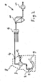
Figur 1 zeigt eine schematische Darstellung eines beispielhaften Zigarettenherstellungsprozesses mit einer erfindungsgemäßen Regelungsanordnung. -
Figur 2 zeigt eine schematische Darstellung eines beispielhaften Zigarettenherstellungsprozesses bei dem die erfindungsgemäße Regelung durch Einsatz eines volumetrischen Verdichters realisiert ist.
-
FIG. 1 shows a schematic representation of an exemplary cigarette manufacturing process with a control arrangement according to the invention. -
FIG. 2 shows a schematic representation of an exemplary cigarette manufacturing process in which the control according to the invention is realized by using a volumetric compressor.
Die beispielhafte erfindungsgemäße Regelungsanordnung weist eine angesteuerte Drosseleinrichtung 5 und eine Messeinrichtung 4 zur Messung des Mengenstroms der von der Luftfördereinrichtung 3, welche im gezeigten Beispiel in die Zigarettenherstellungsmaschine 8 integriert ist, zum Eingang 6 einer Abluftanlage geförderten auf. Die beispielhaft gezeigte Abluftanlage 7 weist dabei eine Unterdruckerzeugungseinrichtung 11 sowie eine Filtereinrichtung 10 auf und verfügt über mehrere Eingänge 6, so dass eine Mehrzahl Zigarettenherstellungsmaschinen 8 mit erfindungsgemäßen Regelungsanordnungen an eine gemeinsame Abluftanlage 7 angeschlossen werden kann. Der Zigarettenfüllstoff 9 wird dabei durch eine Zuführungseinrichtung 1 dem Fördermedium 2 zugeführt. Dabei stellen sich im Bereich der Zuführungseinrichtung 1 abhängig von dem durch das Fördermedium 2 durchtretenden Luftmengenstrom spezifische Ansauggeschwindigkeiten und Strömungsbedingungen ein, die für jeden Zigarettenfüllstoff, insbesondere für jede Tabaksorte, entsprechend optimiert gewählt werden müssen, um optimale Eigenschaften des am Fördermedium 2 gebildeten Tabakstrangs zu erreichen. Das Fördermedium 2 ist im gezeigten Beispiel derart orientiert, dass aufgrund des durch das Fördermedium durchtretenden Luftstroms der Zigarettenfüllstoff an der Unterseite des Fördermediums 2 an die Oberfläche des Fördermediums 2 angedrückt wird.The exemplary control arrangement according to the invention has a controlled
Der durch das Fördermedium 2 durchtretende Luftmengenstrom wird dann durch die Luftfördereinrichtung 3 aus der Zigarettenherstellungsmaschine 8 herausgefördert, wobei im gezeigten Beispiel der Luftmengenstrom dieser aus der Zigarettenherstellungsmaschine 8 herausgeförderten Luft durch die erfindungsgemäße Regelungsanordnung geregelt wird. Nach Passieren der Drosseleinrichtung 5 der beispielhaften Regelungsanordnung erreicht der Luftstrom den Eingang 6 der Abluftanlage 7, wobei der Eingang 6 dafür ausgelegt ist, bei Bedarf eine Mehrzahl Zugarettenherstellungsmaschinen 8 an die Abluftanlage 7 anzuschließen. Die Abluftanlage 7 weist eine Filtereinrichtung 10 auf, welche feinste Zigarettenfüllstoffpartikel aus der Abluft der Zigarettenherstellungsmaschinen herausfiltert, sowie eine Unterdruckerzeugungseinrichtung 11, die geeignet ist, einen Unterdruck zu erzeugen, der zur Entlastung der Luftfördereinrichtung 3 der Zigarettenherstellungsmaschine 8 genutzt werden kann.The air flow rate passing through the conveying medium 2 is then conveyed out of the
In
Claims (15)
dadurch gekennzeichnet,
dass die Regelungsanordnung eine Mengenstromregelung für einen durch das Fördermedium (2) durchtretenden Luftstrom, der den Zigarettenfüllstoff (9) zum Fördermedium (2) transportiert, aufweist.Control arrangement for a cigarette manufacturing machine (8), wherein the cigarette manufacturing machine (8) an air-permeable conveying medium (2) for transporting cigarette filler (9), in particular tobacco or a tobacco product, and an air conveying device (3), wherein the conveying medium (2) for the essential part of the cigarette filler (9) is impermeable,
characterized,
in that the control arrangement has a mass flow control for an air flow which passes through the conveying medium (2) and transports the cigarette filler (9) to the conveying medium (2).
dadurch gekennzeichnet,
dass die Regelungsanordnung eine Messeinrichtung (4) zur Messung des Massen- und/oder Volumenstroms aufweist.Control arrangement according to claim 1,
characterized,
that the control arrangement has a measuring device (4) for measuring the mass and / or volumetric flow.
dadurch gekennzeichnet,
dass die Luftfördereinrichtung (3) eine Verbindung mit einem Eingang einer Abluftanlage (7) aufweist.Control arrangement according to Claim 1 or 2,
characterized,
that the air conveying device (3) has a connection with an input of an extraction system (7).
dadurch gekennzeichnet,
dass die Regelungsanordnung, insbesondere deren Messeinrichtung (4), im Bereich eines von der Luftfördereinrichtung (3) zur Abluftanlage (7) geförderten Luftstroms angeordnet ist.Control arrangement according to claim 3,
characterized,
that the control arrangement, in particular the measuring device (4), in the region of the air conveying device (3) for ventilation system (7) conveyed air flow is arranged.
dadurch gekennzeichnet,
dass die Abluftanlage (7) eine Unterdruckerzeugungseinrichtung (11) aufweist.Control arrangement according to Claim 3 or 4,
characterized,
that the ventilation system (7) comprises a vacuum generating device (11).
dadurch gekennzeichnet,
dass die Regelungsanordnung eine angesteuerte Drosseleinrichtung (5), insbesondere eine Drosselklappe, als Stellglied aufweist.Control arrangement according to one of the preceding claims,
characterized,
that the control arrangement comprises a controlled throttling device (5), in particular a throttle valve as an actuator.
dadurch gekennzeichnet,
dass die Luftfördereinrichtung eine volumetrische Luftfördereinrichtung (3) ist.Control arrangement according to one of the preceding claims,
characterized,
that the air conveyor is a volumetric air conveying device (3).
dadurch gekennzeichnet,
dass die Regelungsanordnung die Einstellung der Verdichterdrehzahl als Stellglied aufweist.Control arrangement according to claim 7,
characterized,
that the control arrangement has the setting of the compressor speed as an actuator.
dadurch gekennzeichnet,
dass der Mengenstrom der durch das Fördermedium (2) durchtretenden, den Zigarettenfüllstoff (9) zum Fördermedium (2) transportierenden Luft geregelt wird.Method for controlling the transport, in particular the mass flow, of the cigarette filler (9), in particular tobacco or a tobacco product, in a cigarette manufacturing machine (8), the cigarette filler (9) being pressed by an air stream to a conveying medium (2) for its delivery, wherein the air flow passes through the conveying medium (2),
characterized,
that the flow rate of the transported medium (2) passing through the cigarette filler (9) for conveying medium (2) transporting air is controlled.
dadurch gekennzeichnet,
dass der Massen- und/oder Volumenstrom der durch das Fördermedium (2) durchtretenden Luft gemessen und vorzugsweise als Regelgröße verwendet wird.Method according to claim 9,
characterized,
that the mass and / or volume flow of the air passing through the conveying medium (2) is measured and preferably used as a controlled variable.
dadurch gekennzeichnet,
dass die Luftfördereinrichtung (3) die durch das Fördermedium durchgetretene Luft in eine Abluftanlage (7) fördert.Method according to claim 9 or 10,
characterized,
that the air conveying device (3) supports the permeated by the fluid air into an exhaust system (7).
dadurch gekennzeichnet,
dass zur Regelung des Mengenstroms der durch das Fördermedium (2) durchtretenden Luft der Mengenstrom der von der Luftfördereinrichtung (3) zur Abluftanlage (7) strömenden Luft gemessen wird.Method according to claim 11,
characterized,
in that, for controlling the flow rate of the air passing through the conveying medium (2), the mass flow of the air flowing from the air conveying device (3) to the exhaust air system (7) is measured.
dadurch gekennzeichnet,
dass durch die Abluftanlage (7) ein Unterdruck der von der Luftfördereinrichtung (3) zur Abluftanlage (7) strömenden Luft erzeugt wird.Method according to one of claims 11 or 12,
characterized,
that through the air extraction system (7), a negative pressure of the air conveying device (3) for ventilation system (7) flowing air is generated.
dadurch gekennzeichnet,
dass das Fördermedium (2) durchtretende Luftstrom durch eine volumetrische Luftfördereinrichtung (3) gefördert wird.Method according to one of the preceding claims,
characterized,
in that the air flow passing through the conveying medium (2) is conveyed through a volumetric air conveying device (3).
dadurch gekennzeichnet,
dass zur Regelung des geförderten Luftstromes eine dem gewünschten Mengenstrom entsprechende Drehzahl der Luftfördereinrichtung eingestellt wird.Method according to claim 14,
characterized,
in that a speed corresponding to the desired flow rate of the air conveying device is set to regulate the conveyed air flow.
Applications Claiming Priority (1)
| Application Number | Priority Date | Filing Date | Title |
|---|---|---|---|
| DE102010054098A DE102010054098A1 (en) | 2010-12-10 | 2010-12-10 | Control arrangement for a cigarette manufacturing machine and method for regulating the transport of the cigarette filler |
Publications (3)
| Publication Number | Publication Date |
|---|---|
| EP2462819A2 true EP2462819A2 (en) | 2012-06-13 |
| EP2462819A3 EP2462819A3 (en) | 2014-12-10 |
| EP2462819B1 EP2462819B1 (en) | 2020-03-18 |
Family
ID=45002527
Family Applications (1)
| Application Number | Title | Priority Date | Filing Date |
|---|---|---|---|
| EP11009086.7A Active EP2462819B1 (en) | 2010-12-10 | 2011-11-16 | Regulation assembly for a cigarette manufacturing machine and method for regulating the transport of the cigarette filler |
Country Status (3)
| Country | Link |
|---|---|
| EP (1) | EP2462819B1 (en) |
| CN (1) | CN102524948B (en) |
| DE (1) | DE102010054098A1 (en) |
Families Citing this family (2)
| Publication number | Priority date | Publication date | Assignee | Title |
|---|---|---|---|---|
| DE102012106180A1 (en) * | 2012-07-10 | 2014-01-16 | Hauni Maschinenbau Ag | Method for controlling a machine combination and / or a machine for processing rod-shaped articles of the tobacco-processing industry and a machine device therefor |
| DE102013004634A1 (en) * | 2013-03-15 | 2014-09-18 | Riedel Filtertechnik Gmbh | Pneumatic conveyor system |
Citations (1)
| Publication number | Priority date | Publication date | Assignee | Title |
|---|---|---|---|---|
| DE1296063B (en) | 1960-05-10 | 1969-05-22 | Molins Organisation Ltd | Rod cigarette machine or the like with an air-permeable conveyor for a continuous tobacco filler |
Family Cites Families (8)
| Publication number | Priority date | Publication date | Assignee | Title |
|---|---|---|---|---|
| GB958209A (en) * | 1959-06-03 | 1964-05-21 | Molins Machine Co Ltd | Improvements in or relating to tobacco manipulating machines |
| JPS58149670A (en) * | 1981-12-09 | 1983-09-06 | モリンス・ピ−エルシ− | Method and apparatus for measuring internal pressure of cigarette rod |
| DE19514925A1 (en) * | 1995-04-22 | 1996-10-24 | Hauni Maschinenbau Ag | Method and device for processing exhaust air from the manufacture of articles in the tobacco processing industry |
| DE10051031A1 (en) * | 2000-10-14 | 2002-04-18 | Hauni Maschinenbau Ag | Method and device for forming a tobacco rod |
| CN1207997C (en) * | 2001-03-23 | 2005-06-29 | 日本烟草产业株式会社 | Shred tobacco feeding apparatus for cigarette wrapping machine |
| DE102004007841A1 (en) * | 2004-02-17 | 2005-09-08 | Hauni Maschinenbau Ag | Stranding machine, method of operating the same and air conveying system |
| DE102006031216A1 (en) * | 2006-06-30 | 2008-01-03 | Hauni Maschinenbau Ag | Flow body in a strand machine of the tobacco processing industry |
| DE102008056296A1 (en) * | 2008-11-07 | 2010-05-12 | Hauni Maschinenbau Ag | Apparatus and method for feeding cut tobacco from a tobacco feeding unit to a tobacco processing machine |
-
2010
- 2010-12-10 DE DE102010054098A patent/DE102010054098A1/en not_active Withdrawn
-
2011
- 2011-10-11 CN CN201110305339.9A patent/CN102524948B/en active Active
- 2011-11-16 EP EP11009086.7A patent/EP2462819B1/en active Active
Patent Citations (1)
| Publication number | Priority date | Publication date | Assignee | Title |
|---|---|---|---|---|
| DE1296063B (en) | 1960-05-10 | 1969-05-22 | Molins Organisation Ltd | Rod cigarette machine or the like with an air-permeable conveyor for a continuous tobacco filler |
Also Published As
| Publication number | Publication date |
|---|---|
| EP2462819B1 (en) | 2020-03-18 |
| CN102524948B (en) | 2015-07-08 |
| CN102524948A (en) | 2012-07-04 |
| EP2462819A3 (en) | 2014-12-10 |
| DE102010054098A1 (en) | 2012-06-14 |
Similar Documents
| Publication | Publication Date | Title |
|---|---|---|
| DE102006011742B3 (en) | Regulating transport quantity of pneumatically transported light material, especially tobacco or tea, involves varying suction pipe cross-section with control flap by demand/actual value equalization of absolute speed of light material | |
| CH706658A1 (en) | Method and apparatus for controlling the supply of fiber to a carding machine. | |
| WO2020038658A1 (en) | Particle-measuring system having a dilution device, and method for measuring particles | |
| DE102013007705B4 (en) | Device and method for operating a pneumatic conveyor in the dense stream by means of controlled overflow valves | |
| DE102008020631B3 (en) | Method for operating a machine of the tobacco processing industry and corresponding machine | |
| EP2462819B1 (en) | Regulation assembly for a cigarette manufacturing machine and method for regulating the transport of the cigarette filler | |
| DE102008063158A1 (en) | Fuel filter assembly | |
| EP1563745A1 (en) | Rod making machine, method of operating the same, and air conveyor system | |
| DE102013004634A1 (en) | Pneumatic conveyor system | |
| EP3691951B1 (en) | Flow device and method for controlling and/or adjusting a pressure in a pneumatic sand-conveying device for a rail vehicle, and sand-conveying device having a flow device | |
| EP2808278B1 (en) | Method for transporting tobacco and corresponding computer programm product | |
| DE102014103971A1 (en) | Device for conveying granular material | |
| EP3691950B1 (en) | Flow device and method for controlling and/or adjusting a counter pressure in a pneumatic sand-conveying device for a rail vehicle, and sand-conveying device having a flow device | |
| DE10305049B4 (en) | Apparatus for pneumatically feeding at least one spinning preparation machine, e.g. Card, cleaner | |
| DE10020162A1 (en) | Method and device for producing a solid or foam-forming, flowable reaction mixture | |
| DE102006009148A1 (en) | Flow body of a cigarette rod machine | |
| DE102017130981B3 (en) | System for providing an aerosol | |
| DE102021104531A1 (en) | Electronic device for detecting granular material inside an agricultural spreader | |
| EP2497381B1 (en) | Regulation assembly for a filter application device and method for regulating the dispensing of process air of a filter application device | |
| CH682921A5 (en) | Device for pneumatic Food least one fiber processing machine, such as card. | |
| DE102016124660A1 (en) | Distributor apparatus and method for controlling the humidity of tobacco | |
| DE102011105647B4 (en) | Pneumatic device or pneumatic system with an oiler device | |
| CH714101A1 (en) | Device for controlling a fiber fluff stream in a cleaner. | |
| DE10054117A1 (en) | Method and device for the pneumatic conveying of bulk material | |
| DE102011005391B4 (en) | Ventilation device of a machine of the tobacco processing industry, such a machine with a ventilation device and a method for ventilating such a machine |
Legal Events
| Date | Code | Title | Description |
|---|---|---|---|
| PUAI | Public reference made under article 153(3) epc to a published international application that has entered the european phase |
Free format text: ORIGINAL CODE: 0009012 |
|
| AK | Designated contracting states |
Kind code of ref document: A2 Designated state(s): AL AT BE BG CH CY CZ DE DK EE ES FI FR GB GR HR HU IE IS IT LI LT LU LV MC MK MT NL NO PL PT RO RS SE SI SK SM TR |
|
| AX | Request for extension of the european patent |
Extension state: BA ME |
|
| PUAL | Search report despatched |
Free format text: ORIGINAL CODE: 0009013 |
|
| AK | Designated contracting states |
Kind code of ref document: A3 Designated state(s): AL AT BE BG CH CY CZ DE DK EE ES FI FR GB GR HR HU IE IS IT LI LT LU LV MC MK MT NL NO PL PT RO RS SE SI SK SM TR |
|
| AX | Request for extension of the european patent |
Extension state: BA ME |
|
| RIC1 | Information provided on ipc code assigned before grant |
Ipc: A24C 5/18 20060101AFI20141104BHEP |
|
| 17P | Request for examination filed |
Effective date: 20150414 |
|
| RBV | Designated contracting states (corrected) |
Designated state(s): AL AT BE BG CH CY CZ DE DK EE ES FI FR GB GR HR HU IE IS IT LI LT LU LV MC MK MT NL NO PL PT RO RS SE SI SK SM TR |
|
| GRAP | Despatch of communication of intention to grant a patent |
Free format text: ORIGINAL CODE: EPIDOSNIGR1 |
|
| STAA | Information on the status of an ep patent application or granted ep patent |
Free format text: STATUS: GRANT OF PATENT IS INTENDED |
|
| INTG | Intention to grant announced |
Effective date: 20180425 |
|
| TPAC | Observations filed by third parties |
Free format text: ORIGINAL CODE: EPIDOSNTIPA |
|
| GRAS | Grant fee paid |
Free format text: ORIGINAL CODE: EPIDOSNIGR3 |
|
| GRAJ | Information related to disapproval of communication of intention to grant by the applicant or resumption of examination proceedings by the epo deleted |
Free format text: ORIGINAL CODE: EPIDOSDIGR1 |
|
| GRAL | Information related to payment of fee for publishing/printing deleted |
Free format text: ORIGINAL CODE: EPIDOSDIGR3 |
|
| STAA | Information on the status of an ep patent application or granted ep patent |
Free format text: STATUS: EXAMINATION IS IN PROGRESS |
|
| 17Q | First examination report despatched |
Effective date: 20180911 |
|
| INTC | Intention to grant announced (deleted) | ||
| GRAP | Despatch of communication of intention to grant a patent |
Free format text: ORIGINAL CODE: EPIDOSNIGR1 |
|
| STAA | Information on the status of an ep patent application or granted ep patent |
Free format text: STATUS: GRANT OF PATENT IS INTENDED |
|
| INTG | Intention to grant announced |
Effective date: 20191122 |
|
| GRAA | (expected) grant |
Free format text: ORIGINAL CODE: 0009210 |
|
| STAA | Information on the status of an ep patent application or granted ep patent |
Free format text: STATUS: THE PATENT HAS BEEN GRANTED |
|
| AK | Designated contracting states |
Kind code of ref document: B1 Designated state(s): AL AT BE BG CH CY CZ DE DK EE ES FI FR GB GR HR HU IE IS IT LI LT LU LV MC MK MT NL NO PL PT RO RS SE SI SK SM TR |
|
| REG | Reference to a national code |
Ref country code: GB Ref legal event code: FG4D Free format text: NOT ENGLISH |
|
| REG | Reference to a national code |
Ref country code: DE Ref legal event code: R096 Ref document number: 502011016545 Country of ref document: DE |
|
| REG | Reference to a national code |
Ref country code: AT Ref legal event code: REF Ref document number: 1244881 Country of ref document: AT Kind code of ref document: T Effective date: 20200415 Ref country code: IE Ref legal event code: FG4D Free format text: LANGUAGE OF EP DOCUMENT: GERMAN |
|
| REG | Reference to a national code |
Ref country code: NL Ref legal event code: FP |
|
| PG25 | Lapsed in a contracting state [announced via postgrant information from national office to epo] |
Ref country code: RS Free format text: LAPSE BECAUSE OF FAILURE TO SUBMIT A TRANSLATION OF THE DESCRIPTION OR TO PAY THE FEE WITHIN THE PRESCRIBED TIME-LIMIT Effective date: 20200318 Ref country code: NO Free format text: LAPSE BECAUSE OF FAILURE TO SUBMIT A TRANSLATION OF THE DESCRIPTION OR TO PAY THE FEE WITHIN THE PRESCRIBED TIME-LIMIT Effective date: 20200618 Ref country code: FI Free format text: LAPSE BECAUSE OF FAILURE TO SUBMIT A TRANSLATION OF THE DESCRIPTION OR TO PAY THE FEE WITHIN THE PRESCRIBED TIME-LIMIT Effective date: 20200318 |
|
| PG25 | Lapsed in a contracting state [announced via postgrant information from national office to epo] |
Ref country code: SE Free format text: LAPSE BECAUSE OF FAILURE TO SUBMIT A TRANSLATION OF THE DESCRIPTION OR TO PAY THE FEE WITHIN THE PRESCRIBED TIME-LIMIT Effective date: 20200318 Ref country code: LV Free format text: LAPSE BECAUSE OF FAILURE TO SUBMIT A TRANSLATION OF THE DESCRIPTION OR TO PAY THE FEE WITHIN THE PRESCRIBED TIME-LIMIT Effective date: 20200318 Ref country code: HR Free format text: LAPSE BECAUSE OF FAILURE TO SUBMIT A TRANSLATION OF THE DESCRIPTION OR TO PAY THE FEE WITHIN THE PRESCRIBED TIME-LIMIT Effective date: 20200318 Ref country code: BG Free format text: LAPSE BECAUSE OF FAILURE TO SUBMIT A TRANSLATION OF THE DESCRIPTION OR TO PAY THE FEE WITHIN THE PRESCRIBED TIME-LIMIT Effective date: 20200618 Ref country code: GR Free format text: LAPSE BECAUSE OF FAILURE TO SUBMIT A TRANSLATION OF THE DESCRIPTION OR TO PAY THE FEE WITHIN THE PRESCRIBED TIME-LIMIT Effective date: 20200619 |
|
| REG | Reference to a national code |
Ref country code: LT Ref legal event code: MG4D |
|
| PG25 | Lapsed in a contracting state [announced via postgrant information from national office to epo] |
Ref country code: SK Free format text: LAPSE BECAUSE OF FAILURE TO SUBMIT A TRANSLATION OF THE DESCRIPTION OR TO PAY THE FEE WITHIN THE PRESCRIBED TIME-LIMIT Effective date: 20200318 Ref country code: RO Free format text: LAPSE BECAUSE OF FAILURE TO SUBMIT A TRANSLATION OF THE DESCRIPTION OR TO PAY THE FEE WITHIN THE PRESCRIBED TIME-LIMIT Effective date: 20200318 Ref country code: CZ Free format text: LAPSE BECAUSE OF FAILURE TO SUBMIT A TRANSLATION OF THE DESCRIPTION OR TO PAY THE FEE WITHIN THE PRESCRIBED TIME-LIMIT Effective date: 20200318 Ref country code: IS Free format text: LAPSE BECAUSE OF FAILURE TO SUBMIT A TRANSLATION OF THE DESCRIPTION OR TO PAY THE FEE WITHIN THE PRESCRIBED TIME-LIMIT Effective date: 20200718 Ref country code: LT Free format text: LAPSE BECAUSE OF FAILURE TO SUBMIT A TRANSLATION OF THE DESCRIPTION OR TO PAY THE FEE WITHIN THE PRESCRIBED TIME-LIMIT Effective date: 20200318 Ref country code: EE Free format text: LAPSE BECAUSE OF FAILURE TO SUBMIT A TRANSLATION OF THE DESCRIPTION OR TO PAY THE FEE WITHIN THE PRESCRIBED TIME-LIMIT Effective date: 20200318 Ref country code: SM Free format text: LAPSE BECAUSE OF FAILURE TO SUBMIT A TRANSLATION OF THE DESCRIPTION OR TO PAY THE FEE WITHIN THE PRESCRIBED TIME-LIMIT Effective date: 20200318 Ref country code: PT Free format text: LAPSE BECAUSE OF FAILURE TO SUBMIT A TRANSLATION OF THE DESCRIPTION OR TO PAY THE FEE WITHIN THE PRESCRIBED TIME-LIMIT Effective date: 20200812 |
|
| REG | Reference to a national code |
Ref country code: DE Ref legal event code: R097 Ref document number: 502011016545 Country of ref document: DE |
|
| PLBE | No opposition filed within time limit |
Free format text: ORIGINAL CODE: 0009261 |
|
| STAA | Information on the status of an ep patent application or granted ep patent |
Free format text: STATUS: NO OPPOSITION FILED WITHIN TIME LIMIT |
|
| PG25 | Lapsed in a contracting state [announced via postgrant information from national office to epo] |
Ref country code: DK Free format text: LAPSE BECAUSE OF FAILURE TO SUBMIT A TRANSLATION OF THE DESCRIPTION OR TO PAY THE FEE WITHIN THE PRESCRIBED TIME-LIMIT Effective date: 20200318 Ref country code: ES Free format text: LAPSE BECAUSE OF FAILURE TO SUBMIT A TRANSLATION OF THE DESCRIPTION OR TO PAY THE FEE WITHIN THE PRESCRIBED TIME-LIMIT Effective date: 20200318 Ref country code: IT Free format text: LAPSE BECAUSE OF FAILURE TO SUBMIT A TRANSLATION OF THE DESCRIPTION OR TO PAY THE FEE WITHIN THE PRESCRIBED TIME-LIMIT Effective date: 20200318 |
|
| 26N | No opposition filed |
Effective date: 20201221 |
|
| PG25 | Lapsed in a contracting state [announced via postgrant information from national office to epo] |
Ref country code: PL Free format text: LAPSE BECAUSE OF FAILURE TO SUBMIT A TRANSLATION OF THE DESCRIPTION OR TO PAY THE FEE WITHIN THE PRESCRIBED TIME-LIMIT Effective date: 20200318 |
|
| PG25 | Lapsed in a contracting state [announced via postgrant information from national office to epo] |
Ref country code: SI Free format text: LAPSE BECAUSE OF FAILURE TO SUBMIT A TRANSLATION OF THE DESCRIPTION OR TO PAY THE FEE WITHIN THE PRESCRIBED TIME-LIMIT Effective date: 20200318 |
|
| PG25 | Lapsed in a contracting state [announced via postgrant information from national office to epo] |
Ref country code: MC Free format text: LAPSE BECAUSE OF FAILURE TO SUBMIT A TRANSLATION OF THE DESCRIPTION OR TO PAY THE FEE WITHIN THE PRESCRIBED TIME-LIMIT Effective date: 20200318 |
|
| REG | Reference to a national code |
Ref country code: CH Ref legal event code: PL |
|
| GBPC | Gb: european patent ceased through non-payment of renewal fee |
Effective date: 20201116 |
|
| PG25 | Lapsed in a contracting state [announced via postgrant information from national office to epo] |
Ref country code: LU Free format text: LAPSE BECAUSE OF NON-PAYMENT OF DUE FEES Effective date: 20201116 |
|
| REG | Reference to a national code |
Ref country code: BE Ref legal event code: MM Effective date: 20201130 |
|
| PG25 | Lapsed in a contracting state [announced via postgrant information from national office to epo] |
Ref country code: LI Free format text: LAPSE BECAUSE OF NON-PAYMENT OF DUE FEES Effective date: 20201130 Ref country code: CH Free format text: LAPSE BECAUSE OF NON-PAYMENT OF DUE FEES Effective date: 20201130 |
|
| PG25 | Lapsed in a contracting state [announced via postgrant information from national office to epo] |
Ref country code: FR Free format text: LAPSE BECAUSE OF NON-PAYMENT OF DUE FEES Effective date: 20201130 Ref country code: IE Free format text: LAPSE BECAUSE OF NON-PAYMENT OF DUE FEES Effective date: 20201116 |
|
| PG25 | Lapsed in a contracting state [announced via postgrant information from national office to epo] |
Ref country code: GB Free format text: LAPSE BECAUSE OF NON-PAYMENT OF DUE FEES Effective date: 20201116 |
|
| REG | Reference to a national code |
Ref country code: AT Ref legal event code: MM01 Ref document number: 1244881 Country of ref document: AT Kind code of ref document: T Effective date: 20201116 |
|
| PG25 | Lapsed in a contracting state [announced via postgrant information from national office to epo] |
Ref country code: AT Free format text: LAPSE BECAUSE OF NON-PAYMENT OF DUE FEES Effective date: 20201116 |
|
| PG25 | Lapsed in a contracting state [announced via postgrant information from national office to epo] |
Ref country code: MT Free format text: LAPSE BECAUSE OF FAILURE TO SUBMIT A TRANSLATION OF THE DESCRIPTION OR TO PAY THE FEE WITHIN THE PRESCRIBED TIME-LIMIT Effective date: 20200318 Ref country code: CY Free format text: LAPSE BECAUSE OF FAILURE TO SUBMIT A TRANSLATION OF THE DESCRIPTION OR TO PAY THE FEE WITHIN THE PRESCRIBED TIME-LIMIT Effective date: 20200318 |
|
| PG25 | Lapsed in a contracting state [announced via postgrant information from national office to epo] |
Ref country code: MK Free format text: LAPSE BECAUSE OF FAILURE TO SUBMIT A TRANSLATION OF THE DESCRIPTION OR TO PAY THE FEE WITHIN THE PRESCRIBED TIME-LIMIT Effective date: 20200318 Ref country code: AL Free format text: LAPSE BECAUSE OF FAILURE TO SUBMIT A TRANSLATION OF THE DESCRIPTION OR TO PAY THE FEE WITHIN THE PRESCRIBED TIME-LIMIT Effective date: 20200318 |
|
| PG25 | Lapsed in a contracting state [announced via postgrant information from national office to epo] |
Ref country code: BE Free format text: LAPSE BECAUSE OF NON-PAYMENT OF DUE FEES Effective date: 20201130 |
|
| P01 | Opt-out of the competence of the unified patent court (upc) registered |
Effective date: 20230516 |
|
| PGFP | Annual fee paid to national office [announced via postgrant information from national office to epo] |
Ref country code: NL Payment date: 20231122 Year of fee payment: 13 |
|
| PGFP | Annual fee paid to national office [announced via postgrant information from national office to epo] |
Ref country code: TR Payment date: 20231113 Year of fee payment: 13 Ref country code: DE Payment date: 20231026 Year of fee payment: 13 |