EP2462393B1 - Vacuum insulation member and refrigerator having a vacuum insulation member - Google Patents
Vacuum insulation member and refrigerator having a vacuum insulation member Download PDFInfo
- Publication number
- EP2462393B1 EP2462393B1 EP10806671.3A EP10806671A EP2462393B1 EP 2462393 B1 EP2462393 B1 EP 2462393B1 EP 10806671 A EP10806671 A EP 10806671A EP 2462393 B1 EP2462393 B1 EP 2462393B1
- Authority
- EP
- European Patent Office
- Prior art keywords
- vacuum insulation
- insulation member
- envelope
- core
- disposed
- Prior art date
- Legal status (The legal status is an assumption and is not a legal conclusion. Google has not performed a legal analysis and makes no representation as to the accuracy of the status listed.)
- Active
Links
- 238000009413 insulation Methods 0.000 title claims description 116
- 229910052751 metal Inorganic materials 0.000 claims description 13
- 239000002184 metal Substances 0.000 claims description 13
- 230000005540 biological transmission Effects 0.000 claims description 9
- 238000010030 laminating Methods 0.000 claims description 6
- 239000000463 material Substances 0.000 claims description 6
- 229920005989 resin Polymers 0.000 claims description 5
- 239000011347 resin Substances 0.000 claims description 5
- 229920003002 synthetic resin Polymers 0.000 claims description 5
- 239000000057 synthetic resin Substances 0.000 claims description 5
- 239000011162 core material Substances 0.000 description 89
- 239000007789 gas Substances 0.000 description 22
- 239000003365 glass fiber Substances 0.000 description 14
- 238000000034 method Methods 0.000 description 12
- 238000001816 cooling Methods 0.000 description 10
- 230000002950 deficient Effects 0.000 description 9
- 230000002829 reductive effect Effects 0.000 description 9
- 239000004088 foaming agent Substances 0.000 description 8
- 239000010410 layer Substances 0.000 description 8
- 230000004888 barrier function Effects 0.000 description 7
- 238000007781 pre-processing Methods 0.000 description 6
- 230000008569 process Effects 0.000 description 6
- 238000003466 welding Methods 0.000 description 5
- IJGRMHOSHXDMSA-UHFFFAOYSA-N Atomic nitrogen Chemical compound N#N IJGRMHOSHXDMSA-UHFFFAOYSA-N 0.000 description 4
- CURLTUGMZLYLDI-UHFFFAOYSA-N Carbon dioxide Chemical compound O=C=O CURLTUGMZLYLDI-UHFFFAOYSA-N 0.000 description 4
- VYPSYNLAJGMNEJ-UHFFFAOYSA-N Silicium dioxide Chemical compound O=[Si]=O VYPSYNLAJGMNEJ-UHFFFAOYSA-N 0.000 description 4
- 238000004519 manufacturing process Methods 0.000 description 4
- 230000002745 absorbent Effects 0.000 description 3
- 239000002250 absorbent Substances 0.000 description 3
- 229910052782 aluminium Inorganic materials 0.000 description 3
- XAGFODPZIPBFFR-UHFFFAOYSA-N aluminium Chemical compound [Al] XAGFODPZIPBFFR-UHFFFAOYSA-N 0.000 description 3
- 238000007731 hot pressing Methods 0.000 description 3
- 239000012774 insulation material Substances 0.000 description 3
- 230000036961 partial effect Effects 0.000 description 3
- 230000035699 permeability Effects 0.000 description 3
- 238000004080 punching Methods 0.000 description 3
- 238000007789 sealing Methods 0.000 description 3
- 239000004743 Polypropylene Substances 0.000 description 2
- 239000000853 adhesive Substances 0.000 description 2
- 230000001070 adhesive effect Effects 0.000 description 2
- 239000005391 art glass Substances 0.000 description 2
- QVGXLLKOCUKJST-UHFFFAOYSA-N atomic oxygen Chemical compound [O] QVGXLLKOCUKJST-UHFFFAOYSA-N 0.000 description 2
- 239000001569 carbon dioxide Substances 0.000 description 2
- 229910002092 carbon dioxide Inorganic materials 0.000 description 2
- 230000008859 change Effects 0.000 description 2
- 239000004744 fabric Substances 0.000 description 2
- 239000000835 fiber Substances 0.000 description 2
- 238000007710 freezing Methods 0.000 description 2
- 230000008014 freezing Effects 0.000 description 2
- 239000001257 hydrogen Substances 0.000 description 2
- 229910052739 hydrogen Inorganic materials 0.000 description 2
- 125000004435 hydrogen atom Chemical class [H]* 0.000 description 2
- 238000001746 injection moulding Methods 0.000 description 2
- 239000012784 inorganic fiber Substances 0.000 description 2
- 239000011810 insulating material Substances 0.000 description 2
- 239000012212 insulator Substances 0.000 description 2
- 229910052757 nitrogen Inorganic materials 0.000 description 2
- 239000001301 oxygen Substances 0.000 description 2
- 229910052760 oxygen Inorganic materials 0.000 description 2
- -1 polypropylene Polymers 0.000 description 2
- 229920001155 polypropylene Polymers 0.000 description 2
- 239000011241 protective layer Substances 0.000 description 2
- 230000000452 restraining effect Effects 0.000 description 2
- 239000000126 substance Substances 0.000 description 2
- 238000010521 absorption reaction Methods 0.000 description 1
- 238000004378 air conditioning Methods 0.000 description 1
- 230000008878 coupling Effects 0.000 description 1
- 238000010168 coupling process Methods 0.000 description 1
- 238000005859 coupling reaction Methods 0.000 description 1
- 230000006837 decompression Effects 0.000 description 1
- 230000001419 dependent effect Effects 0.000 description 1
- 230000000694 effects Effects 0.000 description 1
- 239000005357 flat glass Substances 0.000 description 1
- 238000005187 foaming Methods 0.000 description 1
- 239000011888 foil Substances 0.000 description 1
- 230000000670 limiting effect Effects 0.000 description 1
- 230000005923 long-lasting effect Effects 0.000 description 1
- 238000005192 partition Methods 0.000 description 1
- 230000002093 peripheral effect Effects 0.000 description 1
- 239000004033 plastic Substances 0.000 description 1
- 229920003023 plastic Polymers 0.000 description 1
- 229920000642 polymer Polymers 0.000 description 1
- 229920002635 polyurethane Polymers 0.000 description 1
- 239000004814 polyurethane Substances 0.000 description 1
- 239000000843 powder Substances 0.000 description 1
- 239000000741 silica gel Substances 0.000 description 1
- 229910002027 silica gel Inorganic materials 0.000 description 1
- 239000000377 silicon dioxide Substances 0.000 description 1
- 239000000243 solution Substances 0.000 description 1
- 238000003860 storage Methods 0.000 description 1
- 229920005992 thermoplastic resin Polymers 0.000 description 1
- 238000009423 ventilation Methods 0.000 description 1
Images


Classifications
-
- F—MECHANICAL ENGINEERING; LIGHTING; HEATING; WEAPONS; BLASTING
- F25—REFRIGERATION OR COOLING; COMBINED HEATING AND REFRIGERATION SYSTEMS; HEAT PUMP SYSTEMS; MANUFACTURE OR STORAGE OF ICE; LIQUEFACTION SOLIDIFICATION OF GASES
- F25D—REFRIGERATORS; COLD ROOMS; ICE-BOXES; COOLING OR FREEZING APPARATUS NOT OTHERWISE PROVIDED FOR
- F25D23/00—General constructional features
- F25D23/06—Walls
-
- F—MECHANICAL ENGINEERING; LIGHTING; HEATING; WEAPONS; BLASTING
- F16—ENGINEERING ELEMENTS AND UNITS; GENERAL MEASURES FOR PRODUCING AND MAINTAINING EFFECTIVE FUNCTIONING OF MACHINES OR INSTALLATIONS; THERMAL INSULATION IN GENERAL
- F16L—PIPES; JOINTS OR FITTINGS FOR PIPES; SUPPORTS FOR PIPES, CABLES OR PROTECTIVE TUBING; MEANS FOR THERMAL INSULATION IN GENERAL
- F16L59/00—Thermal insulation in general
- F16L59/06—Arrangements using an air layer or vacuum
- F16L59/065—Arrangements using an air layer or vacuum using vacuum
-
- F—MECHANICAL ENGINEERING; LIGHTING; HEATING; WEAPONS; BLASTING
- F25—REFRIGERATION OR COOLING; COMBINED HEATING AND REFRIGERATION SYSTEMS; HEAT PUMP SYSTEMS; MANUFACTURE OR STORAGE OF ICE; LIQUEFACTION SOLIDIFICATION OF GASES
- F25D—REFRIGERATORS; COLD ROOMS; ICE-BOXES; COOLING OR FREEZING APPARATUS NOT OTHERWISE PROVIDED FOR
- F25D2201/00—Insulation
- F25D2201/10—Insulation with respect to heat
- F25D2201/14—Insulation with respect to heat using subatmospheric pressure
-
- Y—GENERAL TAGGING OF NEW TECHNOLOGICAL DEVELOPMENTS; GENERAL TAGGING OF CROSS-SECTIONAL TECHNOLOGIES SPANNING OVER SEVERAL SECTIONS OF THE IPC; TECHNICAL SUBJECTS COVERED BY FORMER USPC CROSS-REFERENCE ART COLLECTIONS [XRACs] AND DIGESTS
- Y10—TECHNICAL SUBJECTS COVERED BY FORMER USPC
- Y10T—TECHNICAL SUBJECTS COVERED BY FORMER US CLASSIFICATION
- Y10T428/00—Stock material or miscellaneous articles
- Y10T428/23—Sheet including cover or casing
- Y10T428/231—Filled with gas other than air; or under vacuum
Definitions
- the present invention relates to a vacuum insulation member and a refrigerator having a vacuum insulation member, and more particularly, to a vacuum insulation member having a uniform insulation thickness.
- EP 1 724 513 A2 proposes a vacuum insulating material which minimizes the possibility of absorption of moisture or gas components by its core material during storage in the manufacturing process, improves manufacturing efficiency, and maintains and enhances heat insulation performance.
- the known vacuum insulating material comprises: a core material as an inorganic fiber aggregate; an absorbent which absorbs core material gas components; and an envelope with a gas barrier property which encases the core material.
- the absorbent is contained in a housing area made by slitting the core material obliquely with respect to its surface or thickness and the opening of the housing area is narrowed by overlapping.
- DE 10 2006 061085 A1 describes a refrigerating appliance having a cold generator and a cooled interior space, which is surrounded by heat-insulated partition walls.
- the individual limiting walls of evacuated mold parts are formed and connected to a housing, have the form of parts is a honeycomb-shaped support frame which is gas-tight by an outer skin surrounded.
- EP 1 647 759 A2 relates to a vacuum insulation panel which can be used as an insulator for a refrigerator requiring heat insulation to be provided and also to a refrigerator incorporating such a vacuum insulation panel. More particularly, an arrangement for preventing convection spaces from being formed where an edge of the vacuum insulation panel is folded back is proposed.
- the vacuum insulation panel includes a core which has an inner film bag in which a flexible inorganic fiber laminate is accommodated, and an outer barrier bag which is made of gas-impermeable film such as metallic foil laminated film and which accommodates the core.
- the inner film bag includes a welded portion and a ventilation portion.
- the outer barrier bag has a depressurized interior and has been sealed by welding. An edge of the inner film bag is placed in an edge of the outer barrier bag.
- GB 2 446 053 A is concerned with a vacuum panel having external bracing strips to provide a substantially flat sound barrier capable of very high sound rejection independent of frequency.
- internal bracing strips are provided.
- both internal and external bracing strips are provided.
- the panel comprises parallel planar sheets separated by a thin peripheral wall sealing a space evacuated to less than 100 Pa. The strips may be attached centrally of the panel. Alternatively a plurality of strips may be provided on each face.
- EP 1 258 343 A2 is directed to cost-effectively provide a high-strength large vacuum heat-insulating panel with a honeycomb core of non-permeable independent cells by means of simplified instruments and method.
- One goal of the known panel is that the core retains an original shape at its lateral ends from the beginning of a procedure of evacuating air into a vacuum condition till the end of panel bonding, and another is ensuring a long lasting air-tight sealing in the honeycomb core.
- the known vacuum heat-insulating panel includes a vacuum core element of non-permeable honeycomb structure and a surface element bonded thereto by fusing an air-permeable bonding element (woven cloth made of fibrous adhesive of thermoplastic resin or unwoven cloth of the fibrous adhesive). The surface element has its edges bent to provide protection covers.
- JP 2008 025750 A relates to a light transmitting vacuum heat insulation material comprising a gas barring skin material having transparent or translucent protective layers, a transparent or translucent gas barrier layer formed on the protective layers, and a transparent or translucent heat welding layer formed on the gas barrier layer.
- the skin materials are arranged such that the heat welding layers face each other, a transparent or translucent core material is arranged in the middle, and decompression sealing is carried out. Heat welding is carried out on all of the heat welding layers of the skin material in a periphery of the core material.
- the vacuum heat insulation material is transparent or translucent, and when it is used as a heat insulation material for windows by applying it to window glass, a load of air-conditioning can be reduced.
- DE 20 2006 009620 U1 relates to a vacuum insulation panel having a core made up of hexagonal containers fastened together to form a honeycomb. These are filled with silica gel or silica powder. The core is then fitted with a plastic sheath which is evacuated.
- a vacuum insulation member is a sort of insulator decompresses an internal space into a vacuum state to thus use the characteristics of low thermal conductivity of vacuum.
- the vacuum insulation member may be implemented in the form of a panel having a certain thickness.
- the vacuum insulation panel may be configured to include an envelope forming a certain space therein and a core accommodated at an inner side of the envelope and supporting such that the envelope to maintain the certain space.
- a getter for absorbing an internal gas of the envelope may be provided at the inner side of the envelope.
- the envelope (e.g., a film member), serving to maintain an internal vacuum degree of the vacuum insulation member at a certain level, is formed of a film formed by laminating multi-layered polymers and aluminum, or the like.
- glass fiber As the core, glass fiber, silica core, or the like, is used. Among them, glass fiber is commonly used because its excellent initial performance is excellent and its cost is low. However, glass fiber needs a preprocessing process and weak durability.
- the getter is a sort of aspirator or an absorbent for absorbing gas and/or moisture which is present at the inner side of the envelope or newly introduced.
- the core is formed of glass fiber, it is not easy to handle the core, and in order to insert the core into the interior of the envelope, the core needs to undergo a preprocessing process (e.g., hot pressing or needle punching) in order to reduce the volume and size of the core.
- a preprocessing process e.g., hot pressing or needle punching
- the overall thickness of an insulation wall is set and formed based on the portion of the vacuum insulation member which is the thinnest. This, however, causes a problem in that the thickness of the entire insulation wall increases overall.
- the surface of the envelope is creased to be non-uniform.
- a foaming agent could be possibly introduced to the gap due to the creases of the envelope and expanded to cause the vacuum insulation member to be separated. Namely, the defective attachment (or defective bonding) is caused.
- a vacuum insulation member capable of simplifying a preprocessing process of a core, a refrigerator having the vacuum insulation member, and a method for fabricating the vacuum insulation member.
- Another aspect provides a vacuum insulation member capable of obtaining a uniform insulation thickness, a refrigerator having the vacuum insulation member, and a method for fabricating the vacuum insulation member.
- Another aspect provides a vacuum insulation member capable of restraining a generation of creases on an outer surface and reducing a defective attachment, a refrigerator having the vacuum insulation member, and a method for fabricating the vacuum insulation member.
- a vacuum insulation member including: an envelope having gas impermeability and having a certain decompressed space therein; and a core having a certain shape, having an empty space formed therein, and disposed at an inner side of the envelope to support the envelope.
- the core is configured to include a body having a box-like shape with one side open, and a cover for opening and closing the opening of the body.
- Ribs may be provided to be disposed in a thicknesswise direction at an inner side of the body.
- the ribs may be disposed to be perpendicular to each other.
- the ribs may be disposed to cross each other.
- the core may be configured to include a plurality of bodies and a plurality of covers.
- the vacuum insulation member may further include: a getter disposed at the inner side of the envelope and absorbing a gas.
- a through portion is formed on the core to restrain a heat transmission.
- the through portion may be configured to include a slit having a length longer than its width.
- the through portion may be formed such that certain regions overlap with each other with respect to a thicknesswise direction.
- An internal vacuum degree of the envelope may range from 1.33 mPa (10 -5 Torr) to 1.33 Pa (10 -2 Torr).
- the envelope may be configured to include a film main body and a metal laminated film including a laminated layer formed by laminating metal on an outer surface of the film main body.
- a refrigerator having the vacuum insulation member.
- a method for fabricating a vacuum insulation member including: forming an envelope having gas impermeability and a core having a certain shape, having an empty space formed therein, and disposed at an inner side of the envelope to support the envelope; coupling the envelope to an outer side of the core; and decompressing the interior of the envelope to make a certain vacuum degree maintained in the interior of the envelope.
- the core having an empty space formed therein is disposed at the inner side of the envelope to support the envelope, the use of a glass fiber core which needs to under a preprocessing process, for which much equipment and time are required, can be avoided, and thus, the fabrication can be facilitated and the fabrication cost can be reduced.
- the completed vacuum insulation member can have a uniform thickness.
- the thickness of an insulation wall including the vacuum insulation member can be reduced.
- the core is configured to have the box-like shaped body and the cover, a generation of creases on the surface of the envelope after the interior of the envelope is decompressed (exhausted) can be considerably restrained.
- a generation of a defective bonding that the vacuum insulation member is separated from the surface of the object resulting from its expansion according to an introduction of a foaming agent into a gap between creases of the envelope can be considerably reduced.
- the through portion is formed on the core, a heat transmission through the core can be restrained.
- FIG. 1 is sectional view showing a vacuum insulation member according to a first exemplary embodiment of the present invention
- FIG. 2 is a perspective view of a body of FIG. 1
- FIG. 3 is a variant of a core of FIG. 1
- FIG. 4 is a partial plan view showing a variant of ribs of FIG. 3
- FIG. 5 is a variant of a through portion of FIG. 1
- FIG. 6 is a sectional view taken along line VI-VI of FIG. 5 .
- a vacuum insulation member 10a includes an envelope 20 having gas impermeability and having a certain decompressed space therein, and a core 40 having a certain shape, having an empty space formed therein, and disposed at an inner side of the envelope to support the envelope.
- the decompressed space may be a space in which internal pressure is decompressed to be lower than atmospheric pressure.
- the envelope 20 may be configured to have an anti-air permeability or gas impermeability in order to form a decompressed space having a certain vacuum degree therein.
- the envelope 20 may include a plurality of films 21 and 31 which are laminated to each other.
- a junction part 35 may be formed on at least one side of the envelope 20 by bonding the films 21 and 31 at upper and lower sides after the core 40 is accommodated.
- An internal vacuum degree of the envelope 20 may be maintained at 13.3 mPa (10 -4 Torr) to 1.33 Pa (10 -2 Torr).
- the envelope 20 may be configured to include a metal laminated film 21 formed by laminating a metal to have the gas impermeability (anti-air permeability).
- the metal laminated film 21 may be configured to include a film main body formed of a synthetic resin film and a laminated layer 25 formed by laminating a metal (e.g., aluminum (Al)) on the surface of the film main body 23.
- the envelope 20 may further include resin films 31 disposed at an outer side and/or at an inner side of the metal laminated film 21.
- the resin films 31 may be made of polypropylene having excellent chemical resistance.
- a getter 55 may be provided at the inner side of the envelope 20 in order to absorb a gas remaining at the inner side of the envelope 20 or a gas introduced into the interior of the envelope 20 from an outside.
- the getter 55 may be configured to include at least one of BaLi, CoO, BaO, and CaO in order to absorb oxygen, hydrogen, nitrogen, carbon dioxide, and vapor.
- the getter 55 may be configured to have the shape of a certain block or a rectangular parallelepiped.
- the getter 55 may be coated on an inner surface of the envelope or the surface of the core 20.
- the core 40 for supporting the envelope 20 may be provided at the inner side of the envelope 20 in order to form and support a decompressed space having a certain vacuum degree.
- the core 40 may be configured to have the shape of a rectangular parallelepiped with an empty space formed therein. Accordingly, the use of glass fiber core can be avoided, and thus, a preprocessing process (e.g., hot pressing or needle punching, and the like), for which much equipment and much time are required, is not necessarily performed to reduce the size and volume of the glass fiber core resulting from the use of the glass fiber core.
- a preprocessing process e.g., hot pressing or needle punching, and the like
- the deviation of the height (thickness) of the core 20 can be reduced, after the internal space of the envelope 20 is decompressed (vacuumized), a uniform insulation thickness of the vacuum insulation member 10a can be obtained. Namely, when the related art glass fiber core is used, after the internal space of the envelope 20 is decompressed (vacuumized), the thickness of the vacuum insulation member is greatly changed (about 30 percent), while there is little change in the thickness of the vacuum insulation member 10a according to the present exemplary embodiment, obtaining the uniform thickness.
- the envelope 20 is supported by the core 40 having the shape of a rectangular parallelepiped, after the interior of the envelope 20 is vacuumized, a generation of creases on the surface of the envelope 20 can be restrained. Accordingly, when the vacuum insulation member 10a is attached to an object (e.g., a wall surface of the main body of a refrigerator), a generation of a defective bonding that the vacuum insulation member 10a is detached from the object due to the creases of the envelope 20 can be prevented.
- an object e.g., a wall surface of the main body of a refrigerator
- the core 40 may be configured to including a body 42 having a box-like shape (i.e., a rectangular container shape) with one side open and a cover 44 for opening and closing the opening of the body 42.
- the core 40 specifically, the body 42 and the cover 44 are made of a synthetic resin material.
- the body 42 and the cover 44 may be formed through injection molding.
- the thickness of the body 42 and the cover 44 may range from 0.5 mm to 5 mm.
- the thickness is merely illustrative, and the thickness of the body 42 and the cover 44 may be appropriately adjusted in consideration of the thickness and the internal vacuum degree of the vacuum insulation member.
- the height of the core 40 may range from 5 mm to 15 mm such that it corresponds to the thickness of the vacuum insulation member.
- a through portion is formed on the core 40 in order to restrain a heat transmission.
- the through portion is formed through side walls of the body 42 in order to restrain a heat transmission in a thicknesswise (heightwise) direction.
- the through portion may be configured to include a plurality of circular holes.
- the through portion may be formed to have a polygonal shape, an oval shape, and the like.
- the size, shape, and number of the through portions may be appropriately adjusted in consideration of a support strength and an internal vacuum degree.
- the core 40 may be configured to include the body 42 having a box-like shape with one side open, the cover 44 for opening and closing the opening of the body 42, and ribs 66 disposed at the inner side of the body 42.
- the ribs 66 may be disposed along the thicknesswise direction of the core 40.
- the ribs 66 may be configured such that one side (i.e., lower end) thereof is in contact with a lower surface of the body 42 and the other side (i.e., upper end) is in contact with the cover 44.
- the ribs 66 may be formed to cross each other. Accordingly, the internal space of the body 42 may be uniformly demarcated to obtain a uniform support strength.
- the body 42 and the ribs 66 may include through portions.
- the ribs 66 may be disposed to be perpendicular to each other at the inner side of the body 42.
- the ribs 66 may include a plurality of first ribs 67a disposed to be parallel to each other at the inner side of the body 42 and a plurality of second ribs 67b disposed at a right angle with respect to the first ribs 67a.
- the ribs 66, 67a, 67b may be integrally formed with the body 42, or may be configured to be received and disposed at the inner side of the body 42, separately from the body 42.
- through portions 65 may be configured to have a plurality of slits 67 having a length which is long.
- the slits 67 may be disposed to be perpendicular to the thickness (height) of the core 40. Accordingly, a heat transmission in the thicknesswise direction of the core 40 can be restrained.
- the plurality of slits 67 may be formed at each side wall of the core 40.
- the slits 67 may be formed such that certain regions thereof overlaps with each other in the thicknesswise direction of the core 40. Accordingly, a heat transmission in the thicknesswise direction of the core can be more effectively restrained.
- the plurality of slits 67 are formed to be spaced apart in a row in a horizontal direction at one side wall of the core 40, and lower slits 67 may be formed in a row such that both end portions thereof overlap with the upper slits 67 at a lower side of the slits 67.
- the length, width, and number of the slits 67 may be appropriately adjusted.
- the getter 55 is inserted into the interior of the core 40. And then, the envelope 20 is coupled to the exterior of the core 40, the interior of the envelope 20 is decompressed to maintain a certain vacuum degree, and then the envelop 20 is hermetically sealed.
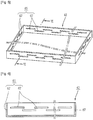
- FIG. 7 is a sectional view of a vacuum insulation member according to a second exemplary embodiment of the present invention
- FIG. 8 is a perspective view of a body of FIG. 7
- FIG. 9 is a variant of the body of FIG. 7 .
- a vacuum insulation member 10b includes the envelope 20 having gas impermeability and having a certain decompressed space therein, and a core 70 having a certain shape, having an empty space formed therein, and disposed at an inner side of the envelope to support the envelope.
- the decompressed space may be a space in which internal pressure is decompressed to be lower than atmospheric pressure.
- the envelope 20 may be configured to have an anti-air permeability or gas impermeability in order to form a decompressed space having a certain vacuum degree (1.33 mPa (10 -5 Torr) to 1.33 Pa (10 -2 Torr)) therein.
- the envelope 20 may include a metal laminated film 21 including a laminated layer 25 formed by laminating a metal (e.g., aluminum) on a surface of a film main body 23 made of a synthetic resin.
- a metal e.g., aluminum
- a junction part 35 may be formed on at least one side of the envelope 20 by bonding the films at upper and lower sides after the core 70 is accommodated.
- the envelope 20 may further include resin films 31 disposed at an outer side and/or at an inner side of the metal laminated film.
- the resin films 31 may be made of polypropylene having excellent chemical resistance.
- a getter 55 may be provided at the inner side of the envelope 20 in order to absorb a gas remaining at the inner side of the envelope 20 or a gas introduced into the interior of the envelope 20 from an outside.
- the getter 55 may be configured to include BaLi, CoO, BaO, CaO, and the like, in order to absorb oxygen, hydrogen, nitrogen, carbon dioxide, and vapor.
- the getter 55 may be configured to have the shape of a certain block or a rectangular parallelepiped.
- the getter 55 may be coated on an inner surface of the envelope or the surface of the core 70.
- the core 70 for supporting the envelope 20 may be provided at the inner side of the envelope 20 in order to form and support a decompressed space having a certain vacuum degree.
- the core 70 may be configured to include a plurality of unit cores 71 having the shape of a rectangular parallelepiped with an empty space formed therein. Accordingly, the use of glass fiber core can be avoided, and thus, a preprocessing process (e.g., hot pressing or needle punching, and the like), for which much equipment and much time are required, is not necessarily performed to reduce the size and volume of the glass fiber core resulting from the use of the glass fiber core.
- a preprocessing process e.g., hot pressing or needle punching, and the like
- the deviation of the height (thickness) of the core 20 can be reduced, after the internal space of the envelope 20 is decompressed (vacuumized), a uniform insulation thickness of the vacuum insulation member 10a can be obtained. Namely, when the related art glass fiber core is used, after the internal space of the envelope 20 is decompressed (vacuumized), the thickness of the vacuum insulation member is greatly changed (about 30 percent), while there is little change in the thickness of the vacuum insulation member 10a according to the present exemplary embodiment, obtaining the uniform thickness.
- the envelope 20 is supported by the core 70 having the shape of a rectangular parallelepiped, after the interior of the envelope 20 is vacuumized, a generation of creases on the surface of the envelope 20 can be restrained. Accordingly, when the vacuum insulation member 10a is attached to an object (e.g., a wall surface of the main body of a refrigerator), a generation of a defective bonding that the vacuum insulation member 10a is detached from the object due to the creases of the envelope 20 can be prevented.
- an object e.g., a wall surface of the main body of a refrigerator
- the size of the vacuum insulation member (panel), namely, the length, width, and thickness of the vacuum insulation member, can be adjusted. Accordingly, vacuum insulation members (panels) of various forms can be easily fabricated.
- the unit core 71 may be configured to including a body 72 having a box-like shape (i.e., a rectangular container shape) with one side open and a cover 74 for opening and closing the opening of the body 42.
- a box-like shape i.e., a rectangular container shape
- the unit core 71 may be made of a synthetic resin material.
- the body 72 and the cover 74 may be formed through injection molding.
- the thickness of the body 72 and the cover 74 may range from 0.5 mm to 5 mm.
- the thickness is merely illustrative, and the thickness of the body 72 and the cover 74 may be appropriately adjusted in consideration of the thickness and the internal vacuum degree of the vacuum insulation member.
- the height of the core 70 may range from 5 mm to 15 mm such that it corresponds to the thickness of the vacuum insulation member.
- Through portions 65 are formed on the core 70 in order to restrain a heat transmission.
- the through portions 65 are formed on a side wall of the body 42 in order to restrain a heat transmission in a thicknesswise (heightwise) direction.
- the through portions 65 may be configured as slits 67 each having a length which is long compared with its width.
- Through portions 67 may be configured to include a plurality of slits.
- the slits 67 may be formed such that certain regions thereof overlap with each other.
- the core 70 may be configured to include a body 82 including a plurality of first body 83a and second body 83b separated in a thicknesswise (heightwise) direction. Accordingly, the height of the body 82, namely, the thickness of the vacuum insulation member 10b, can be easily adjusted.
- the first body 83a may be formed to have a blocked lower surface, and the second body 83b may be formed with upper and lower portions which are all open.
- a plurality of second bodies 83b may be configured.
- a cover 74 may be provided at an upper side of the second body 83b. Accordingly, the number of the second bodies 83b can be adjusted to adjust the thickness.
- an engagement part 85 may be formed at the body of each unit core 71. Accordingly, a generation of a slip between the two bodies which are in contact with each other can be restrained.
- the engagement part 85 may be configured to include a protrusion 87 formed at one side of the body 72 and a receiving part 88 (or a receiving recess or a receiving hole) formed to be recessed to receive the protrusion 87.
- a protrusion 87 formed at one side of the body 72
- a receiving part 88 or a receiving recess or a receiving hole
- the size, shape, and number of the protrusions 87 and receiving parts 88 can be appropriately adjusted.
- FIG. 10 is a sectional view of a refrigerator having a vacuum insulation member according to an exemplary embodiment of the present invention.
- a refrigerator having a vacuum insulation member may be configured to include a refrigerator main body 150 forming a cooling chamber therein, a door 170 for opening and closing the cooling chamber 160, and a vacuum insulation member 10a provided at the refrigerator main body 150 or the door 170.
- the cooling chamber 160 is a general term for a freezing chamber and a refrigerating chamber
- the refrigerator main body 150 may be configured to include one of the freezing chamber and refrigerating chamber.
- the vacuum insulation member 10a may be configured to include the envelope 20 having gas impermeability and having a certain decompressed space therein, and the core 40 having a certain shape, having an empty space formed therein, and disposed at an inner side of the envelope to support the envelope.
- the vacuum insulation member 10a may be further include the getter 55 disposed at the inner side of the envelope 20 to absorb an internal gas.
- the vacuum insulation member 10a may be configured to have the configuration of the vacuum insulation members 10a and 10b as described above with reference to FIGS. 1 to 9 .
- the refrigerator main body 150 includes an outer case 151a forming an external appearance and an inner case disposed to be spaced apart with a charging interval of an insulation member (foaming agent) 151c at an inner side of the outer case 151a and forming the cooling chamber 160 therein.
- the refrigerator main body 150 may include a refrigerating cycle for providing cooling air to the cooling chamber 160.
- a mechanic chamber 180 may be formed at a lower region of a rear side of the refrigerator main body 150.
- the mechanic chamber 180 may include a partial configuration of the refrigerating cycle including a compressor 181, a condenser, and the like, and an evaporator 183 may be provided at one side of the interior of the cooling chamber 160.
- a cooling fan 185 may be provided at one side of the evaporator 183.
- the vacuum insulation member 10a may be provided on at least one side wall of the refrigerator main body 150.
- the thickness of the corresponding side wall can be reduced, and accordingly, the internal space of the refrigerator can be increased as much with the same external appearance (size) maintained.
- the door 170 may include an outer door plate 171a forming an external appearance and an inner door plate 171b spaced apart with a charging interval of the insulation member 171c from the outer door plate 171a at an inner side of the outer door plate 171a.
- the door 170 may include the vacuum insulation member 10a.
- the vacuum insulation member 10a may be provided between the outer door plate 171a and the inner door plate 171b. Accordingly, the thickness of the door 170 can be reduced.
- the vacuum insulation member 10a may be configured such that the envelope 20 is supported by the core formed as a structure having a certain shape, the vacuum insulation member 10a can have a uniform thickness.
- the thickness of the side wall of the refrigerator can be reduced as much.
- the vacuum insulation member 10a has a uniform thickness, so the side wall of the cooling chamber 160 can be formed to be thinner overall, and thus, the internal space of the refrigerator can be increased as much.
- the vacuum insulation member 10a may be configured such that the envelope 20 is supported by the core 20 formed as a structure having the shape of a rectangular parallelepiped, a generation of creases on the surface of the envelope 20 can be restrained. Thus, when the vacuum insulation member 10a is bonded to an object, a defective bonding caused by a generated crease can be restrained.
- the vacuum insulation member 10a is disposed between the outer case 151a and the inner case 151b and fixed to one of the outer case 151a and the inner case 151b before a foaming operation of the refrigerator main body 150.
- the foaming agent polyurethane, and the like
- the foaming agent injected into the interior between the outer case 151a and the inner case 151b expands while flowing within the internal space between the outer case 151a and the inner case 151b.
- vacuum insulation member 10a can be completely tightly attached to the surface of the object (e.g., the outer case 151a or the inner case 151b). Accordingly, the foaming agent is prevented from being introduced to between the vacuum insulation member 10a and the object, restraining a generation of a defective bonding that the vacuum insulation member 10a is detached from the object.
- the body is divided in a vertical direction, but the body in the exemplary embodiment described above with reference to FIGS. 1 to 6 can be also configured to be divided in the vertical direction.
Applications Claiming Priority (2)
| Application Number | Priority Date | Filing Date | Title |
|---|---|---|---|
| KR1020090072993A KR101597554B1 (ko) | 2009-08-07 | 2009-08-07 | 진공단열재 및 진공단열재를 구비한 냉장고 |
| PCT/KR2010/005177 WO2011016697A2 (en) | 2009-08-07 | 2010-08-06 | Vacuum insulation member, registrator having vacuum insulation member, and method for fabricating vacuum insulation member |
Publications (3)
| Publication Number | Publication Date |
|---|---|
| EP2462393A2 EP2462393A2 (en) | 2012-06-13 |
| EP2462393A4 EP2462393A4 (en) | 2016-03-09 |
| EP2462393B1 true EP2462393B1 (en) | 2017-07-19 |
Family
ID=43544804
Family Applications (1)
| Application Number | Title | Priority Date | Filing Date |
|---|---|---|---|
| EP10806671.3A Active EP2462393B1 (en) | 2009-08-07 | 2010-08-06 | Vacuum insulation member and refrigerator having a vacuum insulation member |
Country Status (5)
| Country | Link |
|---|---|
| US (1) | US8778477B2 (ko) |
| EP (1) | EP2462393B1 (ko) |
| KR (1) | KR101597554B1 (ko) |
| ES (1) | ES2642806T3 (ko) |
| WO (1) | WO2011016697A2 (ko) |
Families Citing this family (30)
| Publication number | Priority date | Publication date | Assignee | Title |
|---|---|---|---|---|
| KR101218686B1 (ko) * | 2010-11-21 | 2013-01-24 | 조연수 | 다중 충진 소재와 제조방법 |
| KR101861832B1 (ko) | 2011-11-04 | 2018-05-29 | 엘지전자 주식회사 | 진공 공간부를 구비하는 냉장고 |
| KR101583651B1 (ko) | 2013-03-07 | 2016-01-08 | 주식회사 아모그린텍 | 단열재용 코어 및 그의 제조방법과 이를 이용한 슬림형 단열재 |
| KR102163292B1 (ko) * | 2013-07-26 | 2020-10-08 | 삼성전자주식회사 | 진공단열재 및 이를 포함하는 냉장고 |
| US10052819B2 (en) * | 2014-02-24 | 2018-08-21 | Whirlpool Corporation | Vacuum packaged 3D vacuum insulated door structure and method therefor using a tooling fixture |
| KR102256964B1 (ko) * | 2014-03-28 | 2021-05-27 | 코웨이 주식회사 | 얼음 정수기 |
| KR102228898B1 (ko) * | 2014-07-25 | 2021-03-17 | 삼성전자주식회사 | 냉장고 및 그 제조 방법 |
| KR102366410B1 (ko) * | 2014-10-16 | 2022-02-23 | 삼성전자주식회사 | 냉장고 및 이에 구비되는 진공 단열재 |
| KR102497139B1 (ko) | 2015-08-03 | 2023-02-07 | 엘지전자 주식회사 | 진공단열체 |
| KR102529852B1 (ko) * | 2015-08-03 | 2023-05-08 | 엘지전자 주식회사 | 진공단열체 및 냉장고 |
| KR102502160B1 (ko) | 2015-08-03 | 2023-02-21 | 엘지전자 주식회사 | 진공단열체 및 냉장고 |
| KR102442973B1 (ko) | 2015-08-03 | 2022-09-14 | 엘지전자 주식회사 | 진공단열체 및 냉장고 |
| KR102456642B1 (ko) | 2015-08-03 | 2022-10-19 | 엘지전자 주식회사 | 진공단열체 및 냉장고 |
| KR102447245B1 (ko) | 2015-08-03 | 2022-09-27 | 엘지전자 주식회사 | 진공단열체 및 냉장고 |
| KR102525551B1 (ko) | 2015-08-03 | 2023-04-25 | 엘지전자 주식회사 | 진공단열체 및 냉장고 |
| KR102529853B1 (ko) | 2015-08-03 | 2023-05-08 | 엘지전자 주식회사 | 진공단열체, 진공단열체의 제조방법, 다공성물질패키지, 및 냉장고 |
| KR20170016188A (ko) | 2015-08-03 | 2017-02-13 | 엘지전자 주식회사 | 진공단열체 및 냉장고 |
| EP3332193B1 (en) | 2015-08-03 | 2021-11-17 | LG Electronics Inc. | Vacuum adiabatic body |
| KR102466469B1 (ko) | 2015-08-03 | 2022-11-11 | 엘지전자 주식회사 | 진공단열체 및 냉장고 |
| KR102525550B1 (ko) | 2015-08-03 | 2023-04-25 | 엘지전자 주식회사 | 진공단열체 및 냉장고 |
| KR102498210B1 (ko) | 2015-08-03 | 2023-02-09 | 엘지전자 주식회사 | 진공단열체 및 냉장고 |
| KR102466470B1 (ko) | 2015-08-04 | 2022-11-11 | 엘지전자 주식회사 | 진공단열체 및 냉장고 |
| KR20170047955A (ko) * | 2015-10-26 | 2017-05-08 | 삼성전자주식회사 | 진공단열재, 진공단열재의 제조방법 및 진공단열재를 포함하는 냉장고 |
| KR102466448B1 (ko) | 2017-12-13 | 2022-11-11 | 엘지전자 주식회사 | 진공단열체 및 냉장고 |
| KR102466446B1 (ko) | 2017-12-13 | 2022-11-11 | 엘지전자 주식회사 | 진공단열체 및 냉장고 |
| KR102511095B1 (ko) * | 2017-12-13 | 2023-03-16 | 엘지전자 주식회사 | 진공단열체 및 냉장고 |
| KR102530909B1 (ko) | 2017-12-13 | 2023-05-11 | 엘지전자 주식회사 | 진공단열체 및 냉장고 |
| KR102568737B1 (ko) | 2017-12-13 | 2023-08-21 | 엘지전자 주식회사 | 진공단열체 및 냉장고 |
| KR20200072257A (ko) * | 2018-12-12 | 2020-06-22 | 엘지전자 주식회사 | 진공단열체 및 냉장고 |
| EP4230596A1 (en) * | 2022-02-17 | 2023-08-23 | Thomas Dupont | Vacuum insulation panel with a continuous metal coated polymer core box |
Family Cites Families (17)
| Publication number | Priority date | Publication date | Assignee | Title |
|---|---|---|---|---|
| IT1201945B (it) * | 1982-05-20 | 1989-02-02 | Getters Spa | Tubazione per il trasporto di fluidi isolata a vuoto e metodo per la sua produzione |
| US4791773A (en) * | 1987-02-02 | 1988-12-20 | Taylor Lawrence H | Panel construction |
| US5090981A (en) * | 1990-09-06 | 1992-02-25 | Owens-Corning Fiberglas Corporation | Method for making high R super insulation panel |
| JP3141535B2 (ja) | 1992-05-29 | 2001-03-05 | 藤森工業株式会社 | 真空断熱パネルの製造方法 |
| JP3572990B2 (ja) * | 1999-04-12 | 2004-10-06 | いすゞ自動車株式会社 | 断熱壁部材、およびその製造方法 |
| KR100359056B1 (ko) * | 2000-05-12 | 2002-11-07 | 한국과학기술연구원 | 유리백솜을 이용한 진공단열재 및 그 제조방법 |
| JP3750534B2 (ja) * | 2001-02-20 | 2006-03-01 | いすゞ自動車株式会社 | 真空断熱材および断熱パネル |
| JP2002337256A (ja) * | 2001-05-18 | 2002-11-27 | Jamco Corp | 真空断熱パネルとその製造方法 |
| JP3513142B2 (ja) * | 2002-06-05 | 2004-03-31 | 松下冷機株式会社 | 真空断熱材と断熱体と断熱箱体と断熱扉と貯蔵庫と冷蔵庫 |
| JP2004116695A (ja) * | 2002-09-27 | 2004-04-15 | Nisshinbo Ind Inc | 真空断熱ボード及び該真空断熱ボードを用いた断熱容器 |
| JP2006002920A (ja) | 2004-06-21 | 2006-01-05 | Matsushita Electric Ind Co Ltd | 断熱体 |
| JP4215701B2 (ja) * | 2004-10-12 | 2009-01-28 | 日立アプライアンス株式会社 | 冷蔵庫 |
| JP4215745B2 (ja) * | 2005-05-20 | 2009-01-28 | 日立アプライアンス株式会社 | 真空断熱材、真空断熱材を用いた冷蔵庫及び真空断熱材の製造方法 |
| DE202006009620U1 (de) * | 2006-06-20 | 2006-10-12 | Wedi, Stephan | Vakuum-Isolationsplatte |
| JP2008025750A (ja) * | 2006-07-24 | 2008-02-07 | Asahi Fiber Glass Co Ltd | 光透過性真空断熱材 |
| DE102006061085A1 (de) * | 2006-12-22 | 2008-06-26 | BSH Bosch und Siemens Hausgeräte GmbH | Kältegerät |
| GB0701472D0 (en) * | 2007-01-26 | 2007-03-07 | Rickards Michael J | A braced sound barrier vacuum panel |
-
2009
- 2009-08-07 KR KR1020090072993A patent/KR101597554B1/ko active IP Right Grant
-
2010
- 2010-08-06 WO PCT/KR2010/005177 patent/WO2011016697A2/en active Application Filing
- 2010-08-06 ES ES10806671.3T patent/ES2642806T3/es active Active
- 2010-08-06 US US13/386,744 patent/US8778477B2/en active Active
- 2010-08-06 EP EP10806671.3A patent/EP2462393B1/en active Active
Non-Patent Citations (1)
| Title |
|---|
| None * |
Also Published As
| Publication number | Publication date |
|---|---|
| US20120125039A1 (en) | 2012-05-24 |
| EP2462393A4 (en) | 2016-03-09 |
| US8778477B2 (en) | 2014-07-15 |
| EP2462393A2 (en) | 2012-06-13 |
| KR101597554B1 (ko) | 2016-02-25 |
| WO2011016697A2 (en) | 2011-02-10 |
| WO2011016697A3 (en) | 2011-05-05 |
| ES2642806T3 (es) | 2017-11-20 |
| KR20110015324A (ko) | 2011-02-15 |
Similar Documents
| Publication | Publication Date | Title |
|---|---|---|
| EP2462393B1 (en) | Vacuum insulation member and refrigerator having a vacuum insulation member | |
| EP2462394B1 (en) | Vacuum insulation member, refrigerator having vacuum insulation member, and method for fabricating vacuum insulation member | |
| EP2462391B1 (en) | Vacuum insulation member and method for fabricating an vacuum insulation member | |
| EP2462392B1 (en) | Vacuum insulation member and method for fabricating vacuum insulation member | |
| KR100507783B1 (ko) | 단열 상자 및 이것에 이용하는 진공 단열재 | |
| JP3478771B2 (ja) | 冷蔵庫 | |
| EP2622292B1 (en) | Vacuum insulation panel and a refrigerator with a vacuum insulation panel | |
| KR101495127B1 (ko) | 진공 단열재 및 그것을 사용한 냉장고 | |
| JPH11159693A (ja) | 真空断熱パネル及びその製造方法並びにそれを用いた断熱箱体 | |
| JP2013002484A (ja) | 真空断熱材及びそれを用いた冷蔵庫 | |
| JP2013088036A (ja) | 断熱箱体、冷蔵庫及び貯湯式給湯器 | |
| EP2554759A2 (en) | High-performance vacuum insulation panel and manufacturing method thereof | |
| US20150344173A1 (en) | Vacuum heat insulation material, heat insulation box comprising same, and method for manufacturing vacuum heat insulation material | |
| JP5372877B2 (ja) | 真空断熱材及びそれを用いた冷蔵庫 | |
| KR20100027938A (ko) | 진공 단열재, 진공 단열재를 사용한 냉장고 및 진공 단열재를 사용한 급탕 기기 및 진공 단열재의 제조 방법 | |
| US20180339490A1 (en) | Vacuum insulation material, vacuum insulation material manufacturing method, and refrigerator including vacuum insulation material | |
| JP3549453B2 (ja) | 冷蔵庫 | |
| JPH0763469A (ja) | 真空断熱材 | |
| JP2004286252A (ja) | 断熱パネル | |
| JP6778774B2 (ja) | 真空断熱パネルの製造方法 | |
| JP2009257715A (ja) | 冷蔵庫及び真空断熱材 | |
| JP2015001290A (ja) | 真空断熱材及び冷蔵庫 | |
| JPH07293783A (ja) | 断熱材とそれを用いた断熱箱体 | |
| JP2004212042A (ja) | クーラーボックス | |
| JP2007107877A (ja) | 冷蔵庫 |
Legal Events
| Date | Code | Title | Description |
|---|---|---|---|
| PUAI | Public reference made under article 153(3) epc to a published international application that has entered the european phase |
Free format text: ORIGINAL CODE: 0009012 |
|
| 17P | Request for examination filed |
Effective date: 20120203 |
|
| AK | Designated contracting states |
Kind code of ref document: A2 Designated state(s): AL AT BE BG CH CY CZ DE DK EE ES FI FR GB GR HR HU IE IS IT LI LT LU LV MC MK MT NL NO PL PT RO SE SI SK SM TR |
|
| DAX | Request for extension of the european patent (deleted) | ||
| A4 | Supplementary search report drawn up and despatched |
Effective date: 20160204 |
|
| RIC1 | Information provided on ipc code assigned before grant |
Ipc: F16L 59/065 20060101ALI20160129BHEP Ipc: F25D 23/06 20060101AFI20160129BHEP Ipc: F16L 59/06 20060101ALI20160129BHEP Ipc: F25D 23/00 20060101ALI20160129BHEP |
|
| GRAP | Despatch of communication of intention to grant a patent |
Free format text: ORIGINAL CODE: EPIDOSNIGR1 |
|
| INTG | Intention to grant announced |
Effective date: 20170215 |
|
| RAP1 | Party data changed (applicant data changed or rights of an application transferred) |
Owner name: LG ELECTRONICS INC. |
|
| GRAS | Grant fee paid |
Free format text: ORIGINAL CODE: EPIDOSNIGR3 |
|
| GRAA | (expected) grant |
Free format text: ORIGINAL CODE: 0009210 |
|
| AK | Designated contracting states |
Kind code of ref document: B1 Designated state(s): AL AT BE BG CH CY CZ DE DK EE ES FI FR GB GR HR HU IE IS IT LI LT LU LV MC MK MT NL NO PL PT RO SE SI SK SM TR |
|
| REG | Reference to a national code |
Ref country code: GB Ref legal event code: FG4D |
|
| REG | Reference to a national code |
Ref country code: CH Ref legal event code: EP |
|
| REG | Reference to a national code |
Ref country code: IE Ref legal event code: FG4D |
|
| REG | Reference to a national code |
Ref country code: AT Ref legal event code: REF Ref document number: 910782 Country of ref document: AT Kind code of ref document: T Effective date: 20170815 |
|
| REG | Reference to a national code |
Ref country code: DE Ref legal event code: R096 Ref document number: 602010043773 Country of ref document: DE |
|
| REG | Reference to a national code |
Ref country code: FR Ref legal event code: PLFP Year of fee payment: 8 |
|
| REG | Reference to a national code |
Ref country code: ES Ref legal event code: FG2A Ref document number: 2642806 Country of ref document: ES Kind code of ref document: T3 Effective date: 20171120 |
|
| REG | Reference to a national code |
Ref country code: NL Ref legal event code: MP Effective date: 20170719 |
|
| REG | Reference to a national code |
Ref country code: LT Ref legal event code: MG4D |
|
| REG | Reference to a national code |
Ref country code: AT Ref legal event code: MK05 Ref document number: 910782 Country of ref document: AT Kind code of ref document: T Effective date: 20170719 |
|
| PG25 | Lapsed in a contracting state [announced via postgrant information from national office to epo] |
Ref country code: HR Free format text: LAPSE BECAUSE OF FAILURE TO SUBMIT A TRANSLATION OF THE DESCRIPTION OR TO PAY THE FEE WITHIN THE PRESCRIBED TIME-LIMIT Effective date: 20170719 Ref country code: NL Free format text: LAPSE BECAUSE OF FAILURE TO SUBMIT A TRANSLATION OF THE DESCRIPTION OR TO PAY THE FEE WITHIN THE PRESCRIBED TIME-LIMIT Effective date: 20170719 Ref country code: FI Free format text: LAPSE BECAUSE OF FAILURE TO SUBMIT A TRANSLATION OF THE DESCRIPTION OR TO PAY THE FEE WITHIN THE PRESCRIBED TIME-LIMIT Effective date: 20170719 Ref country code: NO Free format text: LAPSE BECAUSE OF FAILURE TO SUBMIT A TRANSLATION OF THE DESCRIPTION OR TO PAY THE FEE WITHIN THE PRESCRIBED TIME-LIMIT Effective date: 20171019 Ref country code: SE Free format text: LAPSE BECAUSE OF FAILURE TO SUBMIT A TRANSLATION OF THE DESCRIPTION OR TO PAY THE FEE WITHIN THE PRESCRIBED TIME-LIMIT Effective date: 20170719 Ref country code: LT Free format text: LAPSE BECAUSE OF FAILURE TO SUBMIT A TRANSLATION OF THE DESCRIPTION OR TO PAY THE FEE WITHIN THE PRESCRIBED TIME-LIMIT Effective date: 20170719 Ref country code: AT Free format text: LAPSE BECAUSE OF FAILURE TO SUBMIT A TRANSLATION OF THE DESCRIPTION OR TO PAY THE FEE WITHIN THE PRESCRIBED TIME-LIMIT Effective date: 20170719 |
|
| PG25 | Lapsed in a contracting state [announced via postgrant information from national office to epo] |
Ref country code: PL Free format text: LAPSE BECAUSE OF FAILURE TO SUBMIT A TRANSLATION OF THE DESCRIPTION OR TO PAY THE FEE WITHIN THE PRESCRIBED TIME-LIMIT Effective date: 20170719 Ref country code: BG Free format text: LAPSE BECAUSE OF FAILURE TO SUBMIT A TRANSLATION OF THE DESCRIPTION OR TO PAY THE FEE WITHIN THE PRESCRIBED TIME-LIMIT Effective date: 20171019 Ref country code: IS Free format text: LAPSE BECAUSE OF FAILURE TO SUBMIT A TRANSLATION OF THE DESCRIPTION OR TO PAY THE FEE WITHIN THE PRESCRIBED TIME-LIMIT Effective date: 20171119 Ref country code: GR Free format text: LAPSE BECAUSE OF FAILURE TO SUBMIT A TRANSLATION OF THE DESCRIPTION OR TO PAY THE FEE WITHIN THE PRESCRIBED TIME-LIMIT Effective date: 20171020 Ref country code: LV Free format text: LAPSE BECAUSE OF FAILURE TO SUBMIT A TRANSLATION OF THE DESCRIPTION OR TO PAY THE FEE WITHIN THE PRESCRIBED TIME-LIMIT Effective date: 20170719 |
|
| REG | Reference to a national code |
Ref country code: CH Ref legal event code: PL |
|
| REG | Reference to a national code |
Ref country code: DE Ref legal event code: R097 Ref document number: 602010043773 Country of ref document: DE |
|
| PG25 | Lapsed in a contracting state [announced via postgrant information from national office to epo] |
Ref country code: RO Free format text: LAPSE BECAUSE OF FAILURE TO SUBMIT A TRANSLATION OF THE DESCRIPTION OR TO PAY THE FEE WITHIN THE PRESCRIBED TIME-LIMIT Effective date: 20170719 Ref country code: CH Free format text: LAPSE BECAUSE OF NON-PAYMENT OF DUE FEES Effective date: 20170831 Ref country code: DK Free format text: LAPSE BECAUSE OF FAILURE TO SUBMIT A TRANSLATION OF THE DESCRIPTION OR TO PAY THE FEE WITHIN THE PRESCRIBED TIME-LIMIT Effective date: 20170719 Ref country code: LI Free format text: LAPSE BECAUSE OF NON-PAYMENT OF DUE FEES Effective date: 20170831 Ref country code: CZ Free format text: LAPSE BECAUSE OF FAILURE TO SUBMIT A TRANSLATION OF THE DESCRIPTION OR TO PAY THE FEE WITHIN THE PRESCRIBED TIME-LIMIT Effective date: 20170719 Ref country code: MC Free format text: LAPSE BECAUSE OF FAILURE TO SUBMIT A TRANSLATION OF THE DESCRIPTION OR TO PAY THE FEE WITHIN THE PRESCRIBED TIME-LIMIT Effective date: 20170719 |
|
| REG | Reference to a national code |
Ref country code: BE Ref legal event code: MM Effective date: 20170831 |
|
| PLBE | No opposition filed within time limit |
Free format text: ORIGINAL CODE: 0009261 |
|
| STAA | Information on the status of an ep patent application or granted ep patent |
Free format text: STATUS: NO OPPOSITION FILED WITHIN TIME LIMIT |
|
| REG | Reference to a national code |
Ref country code: IE Ref legal event code: MM4A |
|
| PG25 | Lapsed in a contracting state [announced via postgrant information from national office to epo] |
Ref country code: SK Free format text: LAPSE BECAUSE OF FAILURE TO SUBMIT A TRANSLATION OF THE DESCRIPTION OR TO PAY THE FEE WITHIN THE PRESCRIBED TIME-LIMIT Effective date: 20170719 Ref country code: SM Free format text: LAPSE BECAUSE OF FAILURE TO SUBMIT A TRANSLATION OF THE DESCRIPTION OR TO PAY THE FEE WITHIN THE PRESCRIBED TIME-LIMIT Effective date: 20170719 Ref country code: EE Free format text: LAPSE BECAUSE OF FAILURE TO SUBMIT A TRANSLATION OF THE DESCRIPTION OR TO PAY THE FEE WITHIN THE PRESCRIBED TIME-LIMIT Effective date: 20170719 Ref country code: IT Free format text: LAPSE BECAUSE OF FAILURE TO SUBMIT A TRANSLATION OF THE DESCRIPTION OR TO PAY THE FEE WITHIN THE PRESCRIBED TIME-LIMIT Effective date: 20170719 |
|
| 26N | No opposition filed |
Effective date: 20180420 |
|
| PG25 | Lapsed in a contracting state [announced via postgrant information from national office to epo] |
Ref country code: LU Free format text: LAPSE BECAUSE OF NON-PAYMENT OF DUE FEES Effective date: 20170806 |
|
| REG | Reference to a national code |
Ref country code: FR Ref legal event code: PLFP Year of fee payment: 9 |
|
| PG25 | Lapsed in a contracting state [announced via postgrant information from national office to epo] |
Ref country code: IE Free format text: LAPSE BECAUSE OF NON-PAYMENT OF DUE FEES Effective date: 20170806 |
|
| PG25 | Lapsed in a contracting state [announced via postgrant information from national office to epo] |
Ref country code: SI Free format text: LAPSE BECAUSE OF FAILURE TO SUBMIT A TRANSLATION OF THE DESCRIPTION OR TO PAY THE FEE WITHIN THE PRESCRIBED TIME-LIMIT Effective date: 20170719 Ref country code: BE Free format text: LAPSE BECAUSE OF NON-PAYMENT OF DUE FEES Effective date: 20170831 |
|
| PG25 | Lapsed in a contracting state [announced via postgrant information from national office to epo] |
Ref country code: MT Free format text: LAPSE BECAUSE OF NON-PAYMENT OF DUE FEES Effective date: 20170806 |
|
| PG25 | Lapsed in a contracting state [announced via postgrant information from national office to epo] |
Ref country code: HU Free format text: LAPSE BECAUSE OF FAILURE TO SUBMIT A TRANSLATION OF THE DESCRIPTION OR TO PAY THE FEE WITHIN THE PRESCRIBED TIME-LIMIT; INVALID AB INITIO Effective date: 20100806 |
|
| PG25 | Lapsed in a contracting state [announced via postgrant information from national office to epo] |
Ref country code: CY Free format text: LAPSE BECAUSE OF NON-PAYMENT OF DUE FEES Effective date: 20170719 |
|
| PG25 | Lapsed in a contracting state [announced via postgrant information from national office to epo] |
Ref country code: MK Free format text: LAPSE BECAUSE OF FAILURE TO SUBMIT A TRANSLATION OF THE DESCRIPTION OR TO PAY THE FEE WITHIN THE PRESCRIBED TIME-LIMIT Effective date: 20170719 |
|
| PG25 | Lapsed in a contracting state [announced via postgrant information from national office to epo] |
Ref country code: TR Free format text: LAPSE BECAUSE OF FAILURE TO SUBMIT A TRANSLATION OF THE DESCRIPTION OR TO PAY THE FEE WITHIN THE PRESCRIBED TIME-LIMIT Effective date: 20170719 |
|
| PG25 | Lapsed in a contracting state [announced via postgrant information from national office to epo] |
Ref country code: PT Free format text: LAPSE BECAUSE OF FAILURE TO SUBMIT A TRANSLATION OF THE DESCRIPTION OR TO PAY THE FEE WITHIN THE PRESCRIBED TIME-LIMIT Effective date: 20170719 |
|
| PG25 | Lapsed in a contracting state [announced via postgrant information from national office to epo] |
Ref country code: AL Free format text: LAPSE BECAUSE OF FAILURE TO SUBMIT A TRANSLATION OF THE DESCRIPTION OR TO PAY THE FEE WITHIN THE PRESCRIBED TIME-LIMIT Effective date: 20170719 |
|
| PGFP | Annual fee paid to national office [announced via postgrant information from national office to epo] |
Ref country code: GB Payment date: 20220705 Year of fee payment: 13 Ref country code: ES Payment date: 20220908 Year of fee payment: 13 Ref country code: DE Payment date: 20220615 Year of fee payment: 13 |
|
| PGFP | Annual fee paid to national office [announced via postgrant information from national office to epo] |
Ref country code: FR Payment date: 20220705 Year of fee payment: 13 |
|
| P01 | Opt-out of the competence of the unified patent court (upc) registered |
Effective date: 20230523 |
|
| REG | Reference to a national code |
Ref country code: DE Ref legal event code: R119 Ref document number: 602010043773 Country of ref document: DE |
|
| GBPC | Gb: european patent ceased through non-payment of renewal fee |
Effective date: 20230806 |