EP2461238B1 - Appareil d'affichage incluant un dispositif d'entrée - Google Patents
Appareil d'affichage incluant un dispositif d'entrée Download PDFInfo
- Publication number
- EP2461238B1 EP2461238B1 EP11009465.3A EP11009465A EP2461238B1 EP 2461238 B1 EP2461238 B1 EP 2461238B1 EP 11009465 A EP11009465 A EP 11009465A EP 2461238 B1 EP2461238 B1 EP 2461238B1
- Authority
- EP
- European Patent Office
- Prior art keywords
- light
- light source
- source unit
- touch
- input
- Prior art date
- Legal status (The legal status is an assumption and is not a legal conclusion. Google has not performed a legal analysis and makes no representation as to the accuracy of the status listed.)
- Not-in-force
Links
- 239000000758 substrate Substances 0.000 claims description 25
- 239000012780 transparent material Substances 0.000 claims description 2
- 238000010586 diagram Methods 0.000 description 28
- 238000000034 method Methods 0.000 description 15
- 230000005236 sound signal Effects 0.000 description 13
- 230000002452 interceptive effect Effects 0.000 description 12
- 230000002194 synthesizing effect Effects 0.000 description 9
- 239000003086 colorant Substances 0.000 description 7
- 230000006870 function Effects 0.000 description 7
- 230000008859 change Effects 0.000 description 6
- 230000003247 decreasing effect Effects 0.000 description 6
- 230000008878 coupling Effects 0.000 description 5
- 238000010168 coupling process Methods 0.000 description 5
- 238000005859 coupling reaction Methods 0.000 description 5
- 230000000694 effects Effects 0.000 description 5
- 230000008569 process Effects 0.000 description 5
- 238000013459 approach Methods 0.000 description 4
- 238000005286 illumination Methods 0.000 description 3
- 238000012545 processing Methods 0.000 description 3
- 230000003068 static effect Effects 0.000 description 3
- XEEYBQQBJWHFJM-UHFFFAOYSA-N Iron Chemical compound [Fe] XEEYBQQBJWHFJM-UHFFFAOYSA-N 0.000 description 2
- 230000015572 biosynthetic process Effects 0.000 description 2
- 238000003780 insertion Methods 0.000 description 2
- 230000037431 insertion Effects 0.000 description 2
- 238000007639 printing Methods 0.000 description 2
- 238000003908 quality control method Methods 0.000 description 2
- 238000003786 synthesis reaction Methods 0.000 description 2
- 238000007792 addition Methods 0.000 description 1
- 230000005540 biological transmission Effects 0.000 description 1
- 238000006243 chemical reaction Methods 0.000 description 1
- 238000004891 communication Methods 0.000 description 1
- 238000010411 cooking Methods 0.000 description 1
- 238000013500 data storage Methods 0.000 description 1
- 230000001419 dependent effect Effects 0.000 description 1
- 239000011521 glass Substances 0.000 description 1
- 230000003993 interaction Effects 0.000 description 1
- 229910052742 iron Inorganic materials 0.000 description 1
- 239000004973 liquid crystal related substance Substances 0.000 description 1
- 238000007726 management method Methods 0.000 description 1
- 238000004519 manufacturing process Methods 0.000 description 1
- 239000000203 mixture Substances 0.000 description 1
- 238000012986 modification Methods 0.000 description 1
- 230000004048 modification Effects 0.000 description 1
- 230000003287 optical effect Effects 0.000 description 1
- 238000006467 substitution reaction Methods 0.000 description 1
- 230000001360 synchronised effect Effects 0.000 description 1
- 238000005406 washing Methods 0.000 description 1
Images


Classifications
-
- G—PHYSICS
- G06—COMPUTING; CALCULATING OR COUNTING
- G06F—ELECTRIC DIGITAL DATA PROCESSING
- G06F3/00—Input arrangements for transferring data to be processed into a form capable of being handled by the computer; Output arrangements for transferring data from processing unit to output unit, e.g. interface arrangements
- G06F3/01—Input arrangements or combined input and output arrangements for interaction between user and computer
- G06F3/048—Interaction techniques based on graphical user interfaces [GUI]
- G06F3/0484—Interaction techniques based on graphical user interfaces [GUI] for the control of specific functions or operations, e.g. selecting or manipulating an object, an image or a displayed text element, setting a parameter value or selecting a range
- G06F3/04847—Interaction techniques to control parameter settings, e.g. interaction with sliders or dials
-
- G—PHYSICS
- G06—COMPUTING; CALCULATING OR COUNTING
- G06F—ELECTRIC DIGITAL DATA PROCESSING
- G06F3/00—Input arrangements for transferring data to be processed into a form capable of being handled by the computer; Output arrangements for transferring data from processing unit to output unit, e.g. interface arrangements
- G06F3/01—Input arrangements or combined input and output arrangements for interaction between user and computer
- G06F3/03—Arrangements for converting the position or the displacement of a member into a coded form
- G06F3/033—Pointing devices displaced or positioned by the user, e.g. mice, trackballs, pens or joysticks; Accessories therefor
- G06F3/0354—Pointing devices displaced or positioned by the user, e.g. mice, trackballs, pens or joysticks; Accessories therefor with detection of 2D relative movements between the device, or an operating part thereof, and a plane or surface, e.g. 2D mice, trackballs, pens or pucks
- G06F3/03547—Touch pads, in which fingers can move on a surface
-
- G—PHYSICS
- G06—COMPUTING; CALCULATING OR COUNTING
- G06F—ELECTRIC DIGITAL DATA PROCESSING
- G06F3/00—Input arrangements for transferring data to be processed into a form capable of being handled by the computer; Output arrangements for transferring data from processing unit to output unit, e.g. interface arrangements
- G06F3/01—Input arrangements or combined input and output arrangements for interaction between user and computer
- G06F3/03—Arrangements for converting the position or the displacement of a member into a coded form
- G06F3/041—Digitisers, e.g. for touch screens or touch pads, characterised by the transducing means
-
- G—PHYSICS
- G06—COMPUTING; CALCULATING OR COUNTING
- G06F—ELECTRIC DIGITAL DATA PROCESSING
- G06F3/00—Input arrangements for transferring data to be processed into a form capable of being handled by the computer; Output arrangements for transferring data from processing unit to output unit, e.g. interface arrangements
- G06F3/01—Input arrangements or combined input and output arrangements for interaction between user and computer
- G06F3/048—Interaction techniques based on graphical user interfaces [GUI]
- G06F3/0487—Interaction techniques based on graphical user interfaces [GUI] using specific features provided by the input device, e.g. functions controlled by the rotation of a mouse with dual sensing arrangements, or of the nature of the input device, e.g. tap gestures based on pressure sensed by a digitiser
- G06F3/0488—Interaction techniques based on graphical user interfaces [GUI] using specific features provided by the input device, e.g. functions controlled by the rotation of a mouse with dual sensing arrangements, or of the nature of the input device, e.g. tap gestures based on pressure sensed by a digitiser using a touch-screen or digitiser, e.g. input of commands through traced gestures
-
- H—ELECTRICITY
- H05—ELECTRIC TECHNIQUES NOT OTHERWISE PROVIDED FOR
- H05B—ELECTRIC HEATING; ELECTRIC LIGHT SOURCES NOT OTHERWISE PROVIDED FOR; CIRCUIT ARRANGEMENTS FOR ELECTRIC LIGHT SOURCES, IN GENERAL
- H05B45/00—Circuit arrangements for operating light-emitting diodes [LED]
- H05B45/20—Controlling the colour of the light
-
- G—PHYSICS
- G02—OPTICS
- G02B—OPTICAL ELEMENTS, SYSTEMS OR APPARATUS
- G02B6/00—Light guides; Structural details of arrangements comprising light guides and other optical elements, e.g. couplings
- G02B6/0001—Light guides; Structural details of arrangements comprising light guides and other optical elements, e.g. couplings specially adapted for lighting devices or systems
- G02B6/0011—Light guides; Structural details of arrangements comprising light guides and other optical elements, e.g. couplings specially adapted for lighting devices or systems the light guides being planar or of plate-like form
- G02B6/0066—Light guides; Structural details of arrangements comprising light guides and other optical elements, e.g. couplings specially adapted for lighting devices or systems the light guides being planar or of plate-like form characterised by the light source being coupled to the light guide
- G02B6/0068—Arrangements of plural sources, e.g. multi-colour light sources
-
- G—PHYSICS
- G02—OPTICS
- G02B—OPTICAL ELEMENTS, SYSTEMS OR APPARATUS
- G02B6/00—Light guides; Structural details of arrangements comprising light guides and other optical elements, e.g. couplings
- G02B6/0001—Light guides; Structural details of arrangements comprising light guides and other optical elements, e.g. couplings specially adapted for lighting devices or systems
- G02B6/0011—Light guides; Structural details of arrangements comprising light guides and other optical elements, e.g. couplings specially adapted for lighting devices or systems the light guides being planar or of plate-like form
- G02B6/0066—Light guides; Structural details of arrangements comprising light guides and other optical elements, e.g. couplings specially adapted for lighting devices or systems the light guides being planar or of plate-like form characterised by the light source being coupled to the light guide
- G02B6/0073—Light emitting diode [LED]
-
- H—ELECTRICITY
- H03—ELECTRONIC CIRCUITRY
- H03K—PULSE TECHNIQUE
- H03K17/00—Electronic switching or gating, i.e. not by contact-making and –breaking
- H03K17/94—Electronic switching or gating, i.e. not by contact-making and –breaking characterised by the way in which the control signals are generated
- H03K17/96—Touch switches
- H03K17/962—Capacitive touch switches
-
- H—ELECTRICITY
- H03—ELECTRONIC CIRCUITRY
- H03K—PULSE TECHNIQUE
- H03K2217/00—Indexing scheme related to electronic switching or gating, i.e. not by contact-making or -breaking covered by H03K17/00
- H03K2217/94—Indexing scheme related to electronic switching or gating, i.e. not by contact-making or -breaking covered by H03K17/00 characterised by the way in which the control signal is generated
- H03K2217/96—Touch switches
- H03K2217/96042—Touch switches with illumination
-
- H—ELECTRICITY
- H03—ELECTRONIC CIRCUITRY
- H03K—PULSE TECHNIQUE
- H03K2217/00—Indexing scheme related to electronic switching or gating, i.e. not by contact-making or -breaking covered by H03K17/00
- H03K2217/94—Indexing scheme related to electronic switching or gating, i.e. not by contact-making or -breaking covered by H03K17/00 characterised by the way in which the control signal is generated
- H03K2217/96—Touch switches
- H03K2217/96066—Thumbwheel, potentiometer, scrollbar or slider simulation by touch switch
-
- H—ELECTRICITY
- H03—ELECTRONIC CIRCUITRY
- H03K—PULSE TECHNIQUE
- H03K2217/00—Indexing scheme related to electronic switching or gating, i.e. not by contact-making or -breaking covered by H03K17/00
- H03K2217/94—Indexing scheme related to electronic switching or gating, i.e. not by contact-making or -breaking covered by H03K17/00 characterised by the way in which the control signal is generated
- H03K2217/96—Touch switches
- H03K2217/9607—Capacitive touch switches
- H03K2217/960785—Capacitive touch switches with illumination
- H03K2217/96079—Capacitive touch switches with illumination using a single or more light guides
Definitions
- the present invention relates to an image display apparatus comprising a display and an input device able to improve user convenience and an image display apparatus including the same.
- An image display apparatus has a function for displaying an image to a user and a function for outputting an audio signal.
- an input device is used to output a video or audio signal desired by a user or perform other setting functions.
- US 2010/0156508 A1 relates to an operation area provided on a display module side of a cover of an electronic device, where the operation area comprises operation buttons.
- LEDs are arranged to face each operation button and emit light to a first transmissive area of the respective operation button.
- further LEDs are arranged at positions near the first LEDs, along a longitudinal edge of a touch sensor provided at a position that faces the operation area.
- US 2003/0210537 A1 relates to operator panels of apparatuses, for example baking ovens or cooking units, for switching electrical functions of the apparatus.
- the operator panel has a transparent panel, on the front side of which fingertip sized switch surfaces are provided.
- a respective touch sensor switch is arranged on the rear side of the panel.
- a light source spaced from the switch surface is arranged on lateral edges of the panel.
- a light source spaced from the switch surface is arranged on the lateral edges of the panel to illuminate the switch surface or several switch surfaces. Light of the light source propagates in the panel with multiple total reflections on the front side and the rear side and impinges on a scatter zone provided opposite the switch surface.
- a second light source can be provided which radiates light into the panel like the first light source, but can have a different color or intensity than the first light source.
- the color of the uniform illumination may vary by selection of the color of the light radiated from the light source and by selection of the color of the panel or by selection of the color of the scatter zone.
- the switch surface can be illuminated green when the touch sensors switch is turned off and red when it is turned on.
- US 2008/0186736 A1 relates to applications of light guide arrangements for transporting and coupling light via micro-optic surface relief structures.
- An ultrathin light guide layer can be used in keypad lighting, having a thickness of about 50 to about 200 microns. As a result, the light guide layer can be used without any apertures for the keys and buttons. This makes light management easy in order to achieve uniform keypad lighting.
- indicative and decorative effects may be individually controlled via interaction of LEDs and segmented light guide optics.
- a decorative illumination effect may utilize two or more LED colors in order to provide actively changeable color variation such as sliding colors or brightness variation over the illumination area.
- a light guide having at least two LEDs with different colors include status indicators indicative of prevailing battery charge, volume, temperature, incoming calls and messages, connection strength, etc.
- TW M 2008/0186736 A1 relates to a display apparatus having a touch control device including a first circuit board and a second circuit board electrically connected to each other, and a light guiding sheet.
- the first circuit board is disposed on a curved bracket and has a plurality of light emitting elements spaced apart from each other at an arc-shaped side edge of the first circuit board.
- the second circuit board is a flexible printed circuit and has a plurality of trigger regions each aligned with a respective one of the light emitting elements.
- a light guiding sheet is attached to the second circuit board, for guiding light emitted by the light emitting element.
- the light guiding sheet and the second circuit board are attached to the curved bracket.
- an image display apparatus comprises a display to display an image, and an input device adjacent to the display, the input device comprising a first light emitting device (LED) to emit a first light of a first color, a second light emitting device (LED) to emit a second light of a second color, a light guide to receive the first light from the first LED at a first end of the light guide and to receive the second light from the second LED at a second end of the light guide, the light guide to mix the first light and the second light and to output a third light having a third color based on the mixed first and second lights, a touch sensor to detect a touch input, and a light source controller to control an intensity of light from the light guide based on the touch input.
- LED light emitting device
- LED light emitting device
- an input device comprising a first light emitting device (LED) to provide a first light having a first color, a second light emitting device (LED) to provide a second light having a second color, a light guide to receive the first light from the first LED at a first end of the light guide and to receive a second light from the second LED at a second end of the light guide, and the light guide to output a third light having a third color based on a combination of the first light and the second light, a touch sensor to determine a touch input, and a controller to control an intensity of the third light from the light guide based on the determined touch input.
- LED light emitting device
- LED light emitting device
- module and “unit” attached to describe the names of components are used herein to help the understanding of the components and thus they should not be considered as having specific meanings or roles. Accordingly, the terms “module” and “unit” may be used interchangeably.
- FIG. 1 is a diagram showing an image display apparatus including an input device according to an embodiment of the present invention.
- the input device 200 may be included in the image display apparatus 100.
- the input device 200 is arranged in at least a part of a bezel area surrounding a display 180 of the image display apparatus 100.
- the input device 200 includes a plurality of light source units.
- the input device synthesizes light emitted from the light source units and outputs the synthesized light.
- the light emitted from each light source unit is changed in correspondence with touch information of touch input.
- the amount of light emitted from at least one light source unit may be changed according to touch position information of the touch information. Therefore, it is possible to provide an interactive effect in correspondence with touch input.
- the amount of light emitted from at least one light source unit may be changed according to touch number information, touch strength information or touch duration information of touch information.
- the color of light emitted from at least one light source unit may be changed according to touch number information, touch strength information or touch duration information of the touch information. Therefore, it is possible to provide an interactive effect in correspondence with touch input.
- the input device 200 may include a plurality of input keys (not shown) for inputting various input operations.
- the plurality of input keys may be displayed on a substrate of the input device 200 by a printing method, etc.
- Touch input positions may correspond to the plurality of input keys. Therefore, different input operations may be performed according to touch input positions.
- the image display apparatus described in the present specification may include a TV receiver, a mobile phone, a smart phone, a notebook computer, a digital broadcast terminal, a Personal Digital Assistant (PDA), a Portable Multimedia Player (PMP), etc.
- a TV receiver a mobile phone, a smart phone, a notebook computer, a digital broadcast terminal, a Personal Digital Assistant (PDA), a Portable Multimedia Player (PMP), etc.
- PDA Personal Digital Assistant
- PMP Portable Multimedia Player
- the input device 200 is applicable to various image display apparatuses, as described above.
- the input device 200 is applicable to electronic apparatuses such as a washing machine, a refrigerator, an air conditioner, a cooker, a cleaner or an electric iron.
- FIG. 2 is a block diagram showing an example of the input device of FIG. 1 .
- the input device 200 includes a substrate 205, a first light source unit 210, a second light source unit 215, a touch sensor 220, a light guide 230, and a light source controller 250.
- the first light source unit 210 and the second light source unit 215 are arranged spaced apart from each other and may emit respective light.
- the first light source unit 210 and the second light source unit 215 emit different colors.
- the light guide 230 synthesizes the light emitted from the first light source unit 210 and the second light source unit 215 and outputs the synthesized light.
- the light guide 230 may include at least one of a first direction pattern from the first light source unit 210 to the second light source unit 215 or a second direction pattern from the second light source unit 215 to the first light source unit 210.
- a touch input is moved from the first light source unit 210 to the second light source unit 215, the amount of synthesized light is changed and the directivity of the light is increased, which will be described below with reference to FIGs. 17 and 18 .
- the touch sensor 220 detects a touch input.
- the detected touch information is sent to the light source controller 250.
- the detected touch information may include touch position information, touch number information, touch strength information or touch duration information.
- the touch sensor 220 may be implemented using various methods such as a capacitive method or a static pressure method, in order to detect the user touch input.
- FIG. 4 shows a static pressure touch sensor and
- FIG. 6 shows a capacitive touch sensor.
- the light source controller 250 controls the first light source unit 210 and the second light source unit 215. In particular, at least one of a first electrical signal S1 sent to the first light source unit 210 or a second electrical signal S2 sent to the second light source unit 215 is changed according to the touch information detected by the touch sensor 220.
- the light source controller 250 may increase the level or pulse width of the first electrical signal S1 and/or decrease the level or pulse width of the second electrical signal S2, as the touch position information of the touch information detected by the touch sensor 220 becomes closer to the second light source unit 215 than the first light source unit 210.
- the light source controller 250 controls increase in the amount of light emitted from the first light source unit 210 and/or decrease in the amount of light emitted from the second light source unit 215, as the touch position information of the touch information detected by the touch sensor 220 becomes closer to the second light source unit 215 than the first light source unit 210.
- the amount of light By changing the amount of light in this way, the user can perceive an interactive effect corresponding to the touch input.
- the light source controller 250 may change the amount of the light emitted from the first light source unit and the amount of light emitted from the second light source unit in inverse proportion to each other according to the touch position information of the touch information.
- the light source controller 250 may change the level, pulse width or period of the first electrical signal S1 and/or the level, pulse width or period of the second electrical signal S2, according to the touch number information, touch strength information or touch duration information of the touch information detected by the touch sensor 220.
- the light source controller 250 may further increase the level or pulse width of the first electrical signal S1 and/or further decrease the level or pulse width of the second electrical signal S2, when the number of times of touch, the touch strength or the touch duration is increased in a state in which the touch position information of the detected touch information becomes closer to the second light source unit 215 than the first light source unit 210.
- the light source controller 250 may control increase of the amount of light emitted from the first light source unit 210 and/or decrease of the amount of light emitted from the second light source unit 215.
- the light source controller 250 may control further increase of the amount of light emitted from the first light source unit 210 and/or further decrease of the amount of light emitted from the second light source unit 215. By changing the amount of light in this way, the user can perceive an interactive effect corresponding to the touch input.
- the light source controller 250 may change at least one of the period of the first electrical signal S1 or the period of the second electrical signal S2, when the number of times of touch, the touch strength or the touch duration of the detected touch information is changed.
- the color of the light emitted from the first light source unit 210 and/or the color of the light emitted from the second light source unit 215 may be changed.
- the color of the light the user can perceive an interactive effect corresponding to the touch input.
- the light source controller 250 may classify the touch information detected by the touch sensor 220 into touch position information, touch number information, touch strength information and touch duration information.
- the position information may be acquired based on a touch position information signal, the level of which is changed, of touch information signals detected by the touch sensor 220 or the touch number information, the touch strength information or the touch duration information may be acquired according to the number of pulses of the touch information signals detected by the touch sensor 220.
- FIG. 3 is a block diagram showing another example of the input device of FIG. 1 .
- the input device of FIG. 3 is different from the input device of FIG. 2 in that a proximity sensor 240 is further included.
- a proximity sensor 240 is further included.
- the proximity sensor 240 detects a user's finger which approaches the input device within a predetermined range and may be implemented using a sensor using light (photosensor, etc.), a high-frequency oscillator circuit, etc. The detected signal is input to the light source controller 250.
- the light source controller 250 may control emission of light from at least one of the first light source unit 210 or the second light source unit 220, if it is determined that a user approaches the input device within a predetermined range.
- the first light source unit 210 and the second light source unit 215 are in an idle state in which light is not emitted. Then, when the proximity sensor 240 detects that the user approaches the input device within the predetermined range, at least one of the first light source unit 210 and the second light source unit 215 emits light. Thereafter, the user may perform a touch input operation in a state in which the first light source unit 210 or the second light source unit 215 is activated.
- FIG. 4 is an exploded perspective view showing an example of the structure of the input device of FIG. 1
- FIG. 5 is a diagram showing an example of a coupling structure of the input device of FIG. 1 .
- the first light source unit 210 and the second light source unit 215 may be provided at both ends of the touch sensor 220 which may be implemented by a printed circuit board (PCB) and arranged spaced apart from each other.
- PCB printed circuit board
- the first light source unit 210 may emit a first light having a predetermined color.
- the second light source unit 215 may emit a second light having a color different that of the light emitted from the first light source unit 210.
- Each of the light source units 210 and 215 may include a plurality of light sources for emitting light.
- a light emitting diode LED
- the LED may be an inorganic LED or an organic LED.
- the first light source unit 210 and the second light source unit 215 may include a plurality of light sources for emitting light having different colors, respectively.
- the light source units 210 and 215 may emit light having different colors according to conditions.
- the first light source unit 210 includes a plurality of light sources 210a and 210b for emitting a red (R) light and the second light source unit 215 includes a plurality of light sources 215a and 215b for emitting a green (G) light.
- the first light source unit 210 emits the red (R) light and the second light source unit 215 emits the green (G) light.
- the touch sensor 220 may be disposed below the light guide 230. That is, the light guide 230 may be disposed below the substrate 205 and the touch sensor 220 may be disposed below the light guide 230. In particular, the first light source unit 210 and the second light source unit 215 may be disposed at both ends of the touch sensor 220.
- the touch sensor 220 of FIG. 4 may be implemented by a static pressure method, in order to detect a user touch input. Touch information detected by the touch sensor 220 is sent to the light source controller 250.
- the light guide 230 synthesizes the light emitted from the first light source unit 210 and the second light source unit 215 and outputs the synthesized light.
- the light guide 230 couples the first light source unit 210 and the second light source unit 215 to holes corresponding to the first light source unit 210 and the second light source unit 215, directs the light of the first light source unit 210 to the second light source unit 215, and directs the light of the second light source unit 215 to the first light source unit 210.
- FIG. 4 shows the case where the light guide 230 is disposed between the substrate 205 and the touch sensor 220 having the plurality of light source units 210 and 215 attached thereto.
- insertion holes may be formed in the light guide 230 so as to insert the red light source 210a and 210b and the green light sources 215a and 215b provided on both ends of the touch sensor 220 thereinto.
- a reflection layer 231 is disposed between the light guide 230 and the touch sensor 220 such that the synchronized light output from the light guide 230 is not directed to the touch sensor 220.
- the light synthesized by the light guide 230 is output toward the substrate 205.
- the light guide 230 may include at least one of a first direction pattern from the first light source unit 210 to the second light source unit 215 or a second direction pattern from the second light source unit 215 to the first light source unit 210.
- FIG. 5 shows the appearance of the input device 200 in which the substrate 205, the light guide 230 and the touch sensor 230 are sequentially connected, as shown in FIG. 4 .
- the input device 200 may be implemented in the form of a module.
- the light source controller 250 and the proximity sensor 240 may be disposed on a rear surface of the touch sensor 230 implemented by a PCB.
- the substrate 205 transmits and outputs the light synthesized by the light guide 230.
- the substrate 205 may be formed of a transparent material.
- the substrate 205 may be formed of glass or a transparent film.
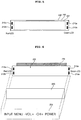
- a plurality of input keys are displayed on the substrate 205.
- a plurality of input keys such as INPUT, MENU, -VOL, VOL+, -CH, CH+ and POWER may be displayed. More specifically, a plurality of input keys may be displayed on the transparent substrate 205 by a printing method, etc.
- the input keys displayed on the substrate 205 are preferably displayed so as to be easily recognized from the synthesized light.
- the input keys displayed on the substrate may be variously changed.
- the touch input position becomes closer to the second light source units 215 than the first light source unit 210, the amount of light emitted from the first light source unit 210 is increased to be greater than the amount of light emitted from the second light source unit 215. Therefore, when the touch input position is moved, it is possible to provide a moving effect.
- FIG. 6 is an exploded perspective view showing another example of the structure of the input device of FIG. 1 .
- the structure of the input device of FIG. 6 is similar to that of the input device of FIG. 5 , except that the position of the touch sensor 220 is disposed between the substrate 205 and the light guide 230, unlike FIG. 5 in which the touch sensor 220 is disposed on the bottom of the input device.
- the reflection layer 231 may be attached to the rear surface of the light guide 230.
- the first light source unit 210 and the second light source unit 215 may be disposed on the light guide 230 and, more particularly, on both ends of the light guide 230 and may be arranged spaced apart from each other.
- the touch sensor 220 may be a capacitive touch sensor.
- the touch information detected by the touch sensor 220 is sent to the light source controller 240.
- the position of the touch sensor 220 may be variously changed.
- FIGs. 7 to 13 are diagrams showing various examples of light display according to touch input positions of the input device of FIG. 1 .
- the touch input position of the user's finger is located at a first position 610 close to the first light source unit 210 at a first time T1 and is then moved to a second position 620 from the first light source unit 210 toward the second light source unit 215 at a second time T2. Then, the touch input position is moved to a middle position 630 between the first light source unit 210 and the second light source unit 215 at a third time T3, is moved to a fourth position 640 close to the second light source unit 215 at a fourth time T4, and is moved to a fifth position 650 closer to the second light source unit 215 at a fifth time T5.
- the light source controller 250 controls the first light source unit 210 or the second light source unit 215 such that at least one of the amount of light emitted from the first light source unit 210 or the amount of light emitted from the second light source unit 215 is changed if the touch input position is changed.
- FIG. 8 shows the principle of synthesizing the light emitted from the first light source unit 210 and the light emitted from the second light source unit 215 according to the embodiment of the present invention.
- red+green yellow
- green+blue cyan
- the first light source unit 210 emits the red light and the second light source unit 215 emits the green light.
- the light guide 220 guides the red light to the second light source unit 215 and guides the green light to the first light source unit 210. If the amount of light emitted from the first light source unit 210 and the amount of light emitted from the second light source unit 215 are identical, as shown in FIG. 8 , a yellow light which is obtained by synthesizing the red light and the green light is displayed on the middle position 630 of the input device 200.
- the intensity of the red light emitted from the first light source unit 210 is gradually decreased toward the second light source unit 215 and the intensity of the green light emitted from the second light source unit 215 is gradually decreased toward the first light source unit 210 such that the yellow light is displayed on the middle position 630 of the input device 200.
- FIG. 9 shows light displayed on the input device 200 in correspondence with the first time T1 of FIG. 7 .
- the touch input position of the user's finger is the first position 610 at the first time T1
- the amount of light emitted from the first light source unit 210 is decreased or the amount of light emitted from the second light source unit 215 such that the yellow light is displayed at the first position 610.
- the light source controller 250 may decrease the level of the signal input to the first light source unit 210 or increase the level of the signal input to the second light source unit 215.
- the light source controller 250 may decrease the pulse width of the signal input to the first light source unit 210 or increase the pulse width of the signal input to the second light source unit 215.
- FIG. 9(a) shows the case where the first electrical signal S1 having a first level V1 is applied to the first light source unit 210 according to a PAM method such that the light emitted from the first light source unit 210 is directed to the second light source unit 215 via the light guide.
- the first level V1 may be a minimum level and the light emitted from the first light source unit 210 may be partially guided.
- the red light emitted from the first light source unit 210 is denoted by an oblique line having an angle of +45 degrees, and a gap between the oblique lines is gradually reduced toward the first light source unit 210.
- FIG. 9(b) shows the case where the second electrical signal S2 having a predetermined level Va is applied to the second light source unit 215 according to a PAM method such that the light emitted from the second light source unit 215 is directed to the first light source unit 210 via the light guide.
- the predetermined level Va may be a maximum level and the amount of light emitted from the second light source unit 215 may be greater than the amount of light emitted from the first light source unit 210.
- the green light emitted from the first light source unit 210 is denoted by an oblique line having an angle of -45 degrees, and a gap between the oblique lines is gradually reduced toward the second light source unit 215.
- FIG. 9(c) shows the case where the red light of FIG. 9(a) and the green light of FIG. 9(b) are synthesized.
- the position of the yellow light obtained by synthesizing the red light and the green light is the first position 610.
- FIG. 10 shows light displayed on the input device 200 in correspondence with the second time T2 of FIG. 7 .
- FIG. 10(a) shows the case where the first electrical signal S1 having a second level V2 is applied to the first light source unit 210 such that the light emitted from the first light source unit 210 is directed to the second light source unit 215 via the light guide.
- the second level is greater than the first level V1 of FIG. 9(a) and the amount of light emitted from the first light source unit 210 is increased as compared to FIG. 9 .
- FIG. 10(b) shows the case where the second electrical signal S2 having a predetermined level Vb is applied to the second light source unit 215 such that the light emitted from the second light source unit 215 is directed to the first light source unit 210 via the light guide.
- the predetermined level Vb is less than the level Va of FIG. 9(b) and the amount of light emitted from the second light source unit 215 is decreased as compared to FIG. 9 .
- FIG. 10(c) shows the case where the red light of FIG. 10(a) and the green light of FIG. 10(b) are synthesized.
- the position of the yellow light obtained by synthesizing the red light and the green light is the first position 620.
- FIGs. 11 to 13 show the case where the amount of light is gradually increased as the level of the first electrical signal S1 input to the first light source unit 210 is gradually increased in order of V3, V4 and V5 and the amount of light is gradually decreased as the level of the second electrical signal S2 input to the second light source unit 215 is gradually decreased in order of Vc, Vd and Ve.
- the position of the yellow light obtained by synthesizing the red light and the green light is changed in order of the third position 630, the fourth position 640 and the fifth position 650.
- FIGs. 9 to 13 show the case where the touch input position moves from the left to the right, when the touch input position reversely moves from the right to the left, the amount of light may be reversely adjusted from the fifth time T5 to the first time T1.
- the light source controller 250 may turn any one of the first light source unit 210 or the second light source unit 215 off.
- the light source controller 250 may supply an off signal to the first light source unit 210 such that the red light is not emitted from the first light source unit 210.
- the second light source unit 215 may emit the green light. Therefore, the light guide 230 may emit only the green light emitted from the second light source unit 215.
- the light source controller 250 may supply an off signal to the second light source unit 215 such that the green light is not emitted from the second light source unit 215.
- the first light source unit 210 may emit the red light. Therefore, the light guide 230 may emit only the red light emitted from the first light source unit 210.
- the touch input position is located at the second light source unit 215, only the red light or the green light may be emitted.
- the light source controller 250 determines that an input key corresponding to a touch input position among the plurality of input keys is operated.
- a plurality of input keys such as an input key, a menu key, a volume key, a channel key and a power key may be displayed on the substrate 205. If the touch input position is located at any one of the plurality of input keys, the light source controller 250 determines that an operation corresponding to the input key is performed. Thus, the light source controller sends a corresponding signal to a controller (170 of FIG. 23 ) of the image display apparatus 10 including the input device 200, which will be described below with reference to FIGs. 14 to 16 .
- FIGs. 14 to 16 are diagrams showing various operation examples of the image display apparatus corresponding to touch input positions.
- FIG. 14(a) if the touch input position is located at the middle position 630 corresponding to the volume key and, more particularly, a Volume Up (VOL+) key of the volume key, as shown in FIG. 14(b) , the audio volume of the image display apparatus 100 is increased.
- FIG. 14 an object 701 representing Volume Up is shown.
- the channel of the image display apparatus 100 may be increased.
- the channel is increased from DTV 7-1 to DTV 8-1.
- a menu object 910 may be displayed on a display 180 of the image display apparatus 100.
- a menu object 910 representing a home menu item, a channel (CH) browser item, a DVR item, etc. is shown.
- the menu object may include a brightness control item, a definition control item, an image quality control item, a horizontal position control item, a vertical position control item, an OSD language control item, etc.
- the light corresponding to each input key is displayed using the light source units 210 and 215 located at both ends of the input device 200, thereby reducing manufacturing costs.
- FIG. 17 is a diagram showing another example of a coupling structure of the input device of FIG. 1
- FIG. 18 is a diagram showing various examples of light display according to touch input positions of the input device of FIG. 17 .
- the light guide 230 may include at least one of a first direction pattern from the first light source unit 210 to the second light source unit 215 or a second direction pattern from the second light source unit 215 to the first light source unit 210.
- a plurality of first direction patterns 1110 from the first light source unit 210 to the second light source unit 215 is formed.
- the first direction patterns 1110 may be formed on the light guide 230 in a groove shape or an insertion shape.
- the first direction patterns may be formed on the substrate 205. More specifically, the first direction patterns may be formed on a lower surface of the substrate 205 which is in contact with the light guide 230.
- the touch input position is moved from the second position 620 to the fourth position 640 through the third position 630, the amount of light emitted from the first light source unit 210 is changed, the amount of light emitted from the second light source unit 215 is changed, the light obtained by synthesizing the light emitted from the first and second light source units is changed, and the directivity of the light is increased by the first direction patterns 1110. Accordingly, it is possible to increase the interactive effect.
- FIGs. 19 to 22 are diagrams showing various examples of light display according to touch input strength of the input device of FIG. 1 .
- each of the first light source unit 210 and the second light source unit 215 includes a plurality of light sources for emitting light having different colors.
- the first light source unit 210 may include a red light source, a green light source and a blue light source.
- the second light source unit 215 may include a green light source, a blue light source and a red light source.
- the first light source unit 210 may emit the blue light and the second light source unit 215 may emit the red light.
- FIG. 20(a) shows the case of applying a first electrical signal S11 having three pulses to the first light source unit 210 according to the strength of the touch input. Then, the blue light is emitted from the first light source unit 210 and is directed to the second light source unit 215 through the light guide. In FIG. 20 , the blue light is denoted by a horizontal line.
- FIG. 20(b) shows the case of applying a second electrical signal S12 having three pulses to the second light source unit 215 according to the strength of the touch input. Then, the red light is emitted from the second light source unit 215 and is directed to the first light source unit 210 through the light guide.
- the red light is denoted by an oblique line having an angle of +45 degrees.
- FIG. 20(c) shows the case of synthesizing the blue light of FIG. 20(a) and the red light of Fig. 20(b) .
- a magenta light may be displayed at the middle position 630.
- the touch input position is changed, similarly to FIG. 7 , at least one of the amount of blue light emitted from the first light source unit 210 or the amount of red light emitted from the second light source unit 215 is changed.
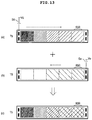
- the first light source unit 210 may emit the green light and the second light source unit 215 may emit the blue light.
- FIG. 21(a) shows the case of applying a first electrical signal S13 having two pulses to the first light source unit 210 according to the strength of the touch input. Then, the green light is emitted from the first light source unit 210 and is directed to the second light source unit 215 through the light guide.
- the green light is denoted by an oblique line having an angle of -45 degrees.
- FIG. 21(b) shows the case of applying a second electrical signal S14 having two pulses to the second light source unit 215 according to the strength of the touch input. Then, the blue light is emitted from the second light source unit 215 and is directed to the first light source unit 210 through the light guide. In FIG. 21 , the blue light is denoted by a horizontal line.
- FIG. 21(c) shows the case of synthesizing the green light of FIG. 21(a) and the blue light of Fig. 21(b) .
- a cyan light may be displayed at the middle position 630.
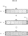
- the first light source unit 210 may emit the red light and the second light source unit 215 may emit the green light.
- FIG. 22(a) shows the case of applying a first electrical signal S15 having one pulse to the first light source unit 210 according to the strength of the touch input. Then, the red light is emitted from the first light source unit 210 and is directed to the second light source unit 215 through the light guide.
- the red light is denoted by an oblique line having an angle of +45 degrees.
- FIG. 22(b) shows the case of applying a second electrical signal S16 having one pulse to the second light source unit 215 according to the strength of the touch input. Then, the green light is emitted from the second light source unit 215 and is directed to the first light source unit 210 through the light guide. In FIG. 22 , the green light is denoted by an oblique line having an angle of -45 degrees.
- FIG. 22(c) shows the case of synthesizing the red light of FIG. 22(a) and the green light of Fig. 22(b) .
- a yellow light may be displayed at the middle position 630.
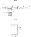
- FIG. 23 is a block diagram of the image display apparatus of FIG. 1 .
- the image display apparatus may be a broadcast display apparatus.
- the image display apparatus 100 may include a broadcast receiver 105, an external device interface 130, a network interface 135, a memory 140, a user input interface 150, a controller 170, a display 180, an audio output unit 185, a power supply 190 and an input device 200.
- the broadcast receiver 105 may include a tuner 110, a demodulator 120 and a network interface 135. As needed, only the tuner 110 and the demodulator may be included or only the network interface 135 may be included.
- the tuner 110 tunes to a Radio Frequency (RF) broadcast signal corresponding to a channel selected by a user from among RF broadcast signals received through an antenna or RF broadcast signals corresponding to all channels previously stored in the image display apparatus.
- RF Radio Frequency
- the tuned RF broadcast is converted into an Intermediate Frequency (IF) signal or a baseband Audio/Video (AV) signal.
- IF Intermediate Frequency
- AV baseband Audio/Video
- the demodulator 120 receives the digital IF signal DIF from the tuner 110 and demodulates the digital IF signal DIF.
- the demodulator 120 may perform demodulation and channel decoding, thereby obtaining a stream signal.
- the stream signal may be a signal in which a video signal, an audio signal and a data signal are multiplexed.
- the stream signal output from the demodulator 120 may be input to the controller 170 and thus subjected to demultiplexing and A/V signal processing.
- the processed video and audio signals are output to the display 180 and the audio output unit 185, respectively.
- the external device interface 130 may serve as an interface between an external device and the image display apparatus 100.
- the external device interface 130 may include an A/V Input/Output (I/O) unit (not shown) and/or a wireless communication module (not shown).
- I/O A/V Input/Output
- wireless communication module not shown
- the network interface 135 serves as an interface between the image display apparatus 100 and a wired/wireless network such as the Internet.
- the network interface 135 may receive content or data provided by an Internet or content provider or a network operator over a network.
- the memory 140 may store various programs necessary for the controller 170 to process and control signals, and may also store processed video, audio and data signals.
- the memory 140 may temporarily store a video, audio and/or data signal received from the external device interface 130.
- the memory 140 may store information about a predetermined broadcast channel by the channel storage function.
- the user input interface 150 transmits a signal input by the user to the controller 170 or transmits a signal received from the controller 170 to the user.
- the input device 200 may synthesize the light emitted from the first light source unit and the light emitted from the second light source unit so as to output the synthesized light and change and output at least one of the amount of light emitted from the first light source unit or the second light source unit according to the touch input position.
- the input device 200 may output the light such that the amount of light emitted from the first light source unit and the amount of light emitted from the second light source unit are inversely proportional to each other according to the touch input position.
- the touch input position information, the touch input number information or the touch input strength information of the input device 200 may be input to the controller 170 through the user input interface 150.
- the input device 200 may be any one of the input devices described with reference to FIGs. 1 to 22 , which will be omitted herein.
- the controller 170 may perform an operation corresponding to the touch input from the input device 200.
- the volume may be controlled as shown in FIG. 14
- the channel may be controlled as shown in FIG. 15
- the menu object may be displayed as shown in FIG. 16 .
- the power on/off operation of the image display apparatus 100 may be performed.
- the controller 170 may control the display of an object corresponding to a touch input position.
- the object 710 representing Volume Up may be displayed on the display 180 as shown in FIG. 14 or the menu object 910 may be displayed as shown in FIG. 16 . Therefore, the user can confirm the operation associated with the input device 200 through the display 180.
- the controller 170 may control the display of the menu object including a brightness control item, a definition control item, an image quality control item, a horizontal position control item, a vertical position control item, an OSD language control item, etc.
- the controller 170 may demultiplex the stream signal received from the tuner 110, the demodulator 120, or the external device interface 130 into a number of signals, process the demultiplexed signals into audio and video data, and output the audio and video data.
- the video signal processed by the controller 170 may be displayed as an image on the display 180.
- the video signal processed by the controller 170 may also be transmitted to an external output device through the external device interface 130.
- the audio signal processed by the controller 170 may be output to the audio output unit 185. Also, the audio signal processed by the controller 170 may be transmitted to the external output device through the external device interface 130.
- the controller 170 may include a DEMUX, a video processor, etc., which will be described below with reference to FIG. 24 .
- the display 180 converts the video signal, the data signal, the OSD signal and the control signal processed by the controller 170 or the video signal, the data signal and the control signal received by the external device interface 130 and generates a driving signal.
- the display 180 may be a projector, a Plasma Display Panel (PDP), a Liquid Crystal Display (LCD), an Organic Light-Emitting Diode (OLED) display or a flexible display.
- the display 180 may be a 3D display.
- the audio output unit 185 receives the audio signal processed by the controller 170 and outputs the received audio signal as sound.
- the power supply 190 supplies power to the image display apparatus 100.
- the power supply 190 may supply power to the controller 170 which may be implemented as a System On Chip (SOC), the display 180 for displaying the video signal, and the audio output unit 185 for outputting the audio signal.
- SOC System On Chip
- the power supply 190 may include a converter (not shown) for converting an AC voltage into a DC voltage.
- the power supply 190 may further include a DC/DC converter for changing the level of the DC voltage and outputting the DC voltage with the changed level.
- the block diagram of the image display apparatus 100 shown in FIG. 23 is an embodiment of the present invention. Some of the components of the block diagram of FIG. 23 may be combined or omitted and new components may be added to the block diagram of FIG. 23 .
- the image display apparatus 100 may be an image display apparatus without a broadcast reception function, e.g., a monitor. In this case, the above-described broadcast receiver 105 may not be included.
- FIG. 24 is a block diagram of the controller of FIG. 23 .
- the controller 170 includes a DEMUX 1810, a video processor 1820, a processor 1830, an OSD generator 1840, a mixer 1845, a frame rate converter (FRC) 1850, and a formatter 1860.
- the controller 170 may further include an audio processor (not shown) and a data processor (not shown).
- the DEMUX 1810 demultiplexes an input stream into a video signal, an audio signal, and a data signal.
- the stream signal input to the DEMUX 1810 may be received from the tuner 110, the demodulator 120 or the external device interface 135.
- the video processor 1820 may process the demultiplexed video signal.
- the video processor 1820 may include a video decoder 1825 and a scaler 1835.
- the video decoder 1825 decodes the demultiplexed video signal and the scaler 1835 scales the resolution of the decoded video signal so that the video signal can be displayed on the display 180.
- the video decoder 1825 may be provided with decoders that operate based on various standards.
- the processor 1830 may control the overall operation of the image display apparatus 100 or the controller 170.
- the processor 1830 controls the tuner 110 to tune to a channel selected by the user and controls the image display apparatus 100 by a user command input through the user input interface 150 or an internal program.
- the processor 1830 may control the operations of the DEMUX 1810, the video processor 1820 and the OSD generator 1840 of the controller 170.
- the OSD generator 1840 generates an OSD signal autonomously or according to user input.
- the OSD generator 1840 may generate signals, by which a variety of information is displayed as images or text on the screen of the display 180, according to a user input signal received through the input device 200.
- the OSD signal may include various data such as a UI, a variety of menu screens, widgets, icons, etc. of the image display apparatus 100.
- the mixer 1845 may mix the decoded video signal processed by the video processor 1820 with the OSD signal generated by the OSD generator 1840 and output the mixed signal to the FRC 1850.
- the FRC 1850 may change the frame rate of an input image.
- the FRC 1850 may maintain the frame rate of the input image without frame rate conversion.
- the formatter 1860 receives the mixed signal from the mixer 1845, that is, the OSD signal and the decoded video signal, changes the format of the mixed signal to be suitable for the display 180.
- the formatter 1860 may convert a received signal into an RGB data signal.
- the RGB signal may be output in the form of a Low Voltage Differential Signal (LVDS) or mini-LVDS.
- LVDS Low Voltage Differential Signal
- the formatter 1860 may divide the video signal into a 2D image signal and a 3D video signal, for 3D video display.
- the formatter 1860 may change the format of the 3D video signal or convert a 2D video signal into a 3D video signal.
- the audio processor (not shown) of the controller 170 may process the demultiplexed audio signal.
- the audio processor (not shown) may have a plurality of decoders.
- the audio processor (not shown) of the controller 170 may also adjust the bass, treble or volume of the audio signal.
- the data processor (not shown) of the controller 170 may process the demultiplexed data signal. For example, if the demultiplexed data signal is an encoded signal, the controller 170 may decode the data signal.
- the encoded data signal may be an EPG which includes broadcasting information specifying the start time, end time, etc. of scheduled broadcast programs.
- the block diagram of the controller 170 illustrated in FIG. 4 is an embodiment of the present invention. Depending upon the specifications of the controller 170, the components of the controller 170 may be combined, or omitted. Or new components are added to the controller 170.
- the FRC 1850 and the formatter 1860 may not be included in the controller 170 and may be separately provided or omitted.
- FIG. 25 is a diagram showing an image display apparatus including an input device according to another embodiment of the present invention.
- the image display apparatus 1900 of FIG. 25 may be a mobile terminal including a display 1980 and an input device 200.
- the mobile terminal 1900 may be a mobile phone, a PMP, an e-book, an MP3 player, a music player, etc.
- the input devices 200 described with reference to FIGs. 1 to 22 are applicable to a mobile terminal.
- the mobile terminal it is possible to increase an interactive effect by adjusting the amount of light according to a touch input position.
- a touch input is performed between first and second light source units arranged spaced apart from each other, at least one of a first electrical signal sent to the first light source unit or a second electrical signal sent to the second light source unit is changed according to touch information such that at least one of the amount of light emitted from the first light source unit or the amount of light emitted from the second light source unit is changed. That is, it is possible to provide an interactive effect during the touch input. Accordingly, it is possible to improve user convenience.
- An image display apparatus including an input device according to an embodiment of the present invention displays an object corresponding to a touch input position so as to variously implement a menu configuration according to the position.
- the image display apparatus may be implemented as code that can be written to a computer-readable recording medium and can thus be read by a processor included in an image display device.
- the computer-readable recording medium may be any type of recording device in which data can be stored in a computer-readable manner. Examples of the computer-readable recording medium include a ROM, a RAM, a CD-ROM, a magnetic tape, a floppy disc, an optical data storage, and a carrier wave (e.g., data transmission over the Internet).
- the computer-readable recording medium can be distributed over a plurality of computer systems connected to a network so that computer-readable code is written thereto and executed therefrom in a decentralized manner. Functional programs, code, and code segments needed for realizing the embodiments herein can be construed by one of ordinary skill in the art.
Landscapes
- Engineering & Computer Science (AREA)
- General Engineering & Computer Science (AREA)
- Theoretical Computer Science (AREA)
- Human Computer Interaction (AREA)
- Physics & Mathematics (AREA)
- General Physics & Mathematics (AREA)
- User Interface Of Digital Computer (AREA)
- Position Input By Displaying (AREA)
- Illuminated Signs And Luminous Advertising (AREA)
- Control Of Indicators Other Than Cathode Ray Tubes (AREA)
- Input From Keyboards Or The Like (AREA)
Claims (2)
- Appareil (100) d'affichage d'image comprenant :un affichage (180) adapté pour afficher une image ; etun dispositif d'entrée (200) adjacent à l'affichage (180), le dispositif d'entrée (200) comprenant :un capteur tactile (220) adapté pour détecter une entrée tactile,un premier dispositif d'émission de lumière (210) adapté pour émettre une première lumière d'une première couleur,un deuxième dispositif d'émission de lumière (215) adapté pour émettre une deuxième lumière d'une deuxième couleur,un substrat (205) formé d'un matériau transparent et adapté pour afficher une pluralité de touches d'entrée,un guide de lumière (230) adapté pour recevoir la première lumière provenant du premier dispositif d'émission de lumière (210) au niveau d'une première extrémité du guide de lumière (230) et pour recevoir la deuxième lumière provenant du deuxième dispositif d'émission de lumière (215) au niveau d'une deuxième extrémité du guide de lumière (230), le guide de lumière (230) étant adapté pour mélanger la première lumière et la deuxième lumière et pour délivrer en sortie une troisième lumière ayant une troisième couleur basée sur les première et deuxième lumières mélangées, etun contrôleur (250) de source de lumière adapté pour commander le premier dispositif d'émission de lumière (210) et le deuxième dispositif d'émission de lumière (215),caractérisé en ce que :une couche de réflexion (231) est disposée entre le guide de lumière (230) et le capteur tactile (220),le premier dispositif d'émission de lumière (210) est agencé au niveau d'une extrémité du guide de lumière (230),le deuxième dispositif d'émission de lumière (215) est agencé au niveau d'une autre extrémité du guide de lumière (230),le guide de lumière (230) est disposé entre le substrat (205) et le capteur tactile (220),la deuxième couleur est différente de la première couleur, etle contrôleur (250) de source de lumière est en outre adapté :pour augmenter une quantité de la première lumière émise à partir du premier dispositif d'émission de lumière (210) lorsque l'entrée tactile détectée est plus près du deuxième dispositif d'émission de lumière (215) que du premier dispositif d'émission de lumière (210), pour diminuer une quantité de la deuxième lumière émise à partir du deuxième dispositif d'émission de lumière (215) lorsque l'entrée tactile détectée est plus près du deuxième dispositif d'émission de lumière (215) que du premier dispositif d'émission de lumière (210), et pour commander l'intensité de la troisième lumière provenant du guide de lumière (230) sur la base d'un nombre d'entrées tactiles ou pour commander l'intensité de la troisième lumière provenant du guide de lumière sur la base d'une intensité de toucher de l'entrée tactile.
- Appareil (100) d'affichage d'image selon la revendication 1, comprenant en outre une zone d'encadrement adjacente à l'affichage (180), dans lequel le dispositif d'entrée (200) est prévu dans la zone d'encadrement.
Applications Claiming Priority (2)
| Application Number | Priority Date | Filing Date | Title |
|---|---|---|---|
| KR1020100121722A KR101787620B1 (ko) | 2010-12-02 | 2010-12-02 | 빛의 합성을 이용한 디스플레이 장치 |
| KR1020110072399A KR101836844B1 (ko) | 2011-07-21 | 2011-07-21 | 입력 장치 및 이를 포함하는 영상표시장치 |
Publications (3)
| Publication Number | Publication Date |
|---|---|
| EP2461238A2 EP2461238A2 (fr) | 2012-06-06 |
| EP2461238A3 EP2461238A3 (fr) | 2014-03-19 |
| EP2461238B1 true EP2461238B1 (fr) | 2017-06-28 |
Family
ID=45421750
Family Applications (1)
| Application Number | Title | Priority Date | Filing Date |
|---|---|---|---|
| EP11009465.3A Not-in-force EP2461238B1 (fr) | 2010-12-02 | 2011-11-30 | Appareil d'affichage incluant un dispositif d'entrée |
Country Status (3)
| Country | Link |
|---|---|
| US (1) | US9218115B2 (fr) |
| EP (1) | EP2461238B1 (fr) |
| CN (1) | CN102622124B (fr) |
Families Citing this family (8)
| Publication number | Priority date | Publication date | Assignee | Title |
|---|---|---|---|---|
| CN103809788A (zh) * | 2012-11-07 | 2014-05-21 | 林志忠 | 具光电转换的触控装置 |
| KR102220825B1 (ko) * | 2013-09-05 | 2021-03-02 | 삼성전자주식회사 | 전자 장치와 전자 장치의 콘텐트 표시방법 |
| TW201601035A (zh) * | 2014-06-18 | 2016-01-01 | Yi Cheng Prec Optronics Co Ltd | 具觸控功能之導光裝置 |
| KR102310870B1 (ko) | 2015-01-12 | 2021-10-12 | 삼성전자주식회사 | 디스플레이 장치 및 그 제어 방법 |
| DE102016216126A1 (de) | 2016-08-26 | 2018-03-01 | Dometic Sweden Ab | Kühleinrichtung für ein Freizeitfahrzeug |
| US10790823B1 (en) * | 2018-05-16 | 2020-09-29 | Valve Corporation | Proximity-based power switch appearance |
| CN112956282A (zh) | 2018-11-13 | 2021-06-11 | 瑞伟安知识产权控股有限公司 | 用于控制光源的系统和方法 |
| EP3697177B1 (fr) * | 2019-02-14 | 2021-01-13 | GIRA GIERSIEPEN GmbH & Co. KG | Capteur tactile pourvu de conduit de lumière intégré |
Citations (1)
| Publication number | Priority date | Publication date | Assignee | Title |
|---|---|---|---|---|
| TWM381807U (en) * | 2010-01-06 | 2010-06-01 | Amtran Technology Co Ltd | Display device and touch-control device thereof |
Family Cites Families (132)
| Publication number | Priority date | Publication date | Assignee | Title |
|---|---|---|---|---|
| EP0650301B1 (fr) | 1993-10-26 | 2000-05-31 | Matsushita Electric Industrial Co., Ltd. | Appareil d'affichage d'images tridimensionnelles |
| JP3459721B2 (ja) | 1995-05-22 | 2003-10-27 | キヤノン株式会社 | 立体画像表示方法及びそれを用いた立体画像表示装置 |
| US7190518B1 (en) | 1996-01-22 | 2007-03-13 | 3Ality, Inc. | Systems for and methods of three dimensional viewing |
| US6064424A (en) | 1996-02-23 | 2000-05-16 | U.S. Philips Corporation | Autostereoscopic display apparatus |
| GB2320156A (en) | 1996-12-07 | 1998-06-10 | Sharp Kk | Directional display and method of making a mask for a directional display |
| EP0879991A3 (fr) * | 1997-05-13 | 1999-04-21 | Matsushita Electric Industrial Co., Ltd. | Système d'illumination |
| US7209585B2 (en) | 2001-06-14 | 2007-04-24 | Sony Corporation | Picture image generation and printed material production apparatus, and a method thereof |
| DE10133135C5 (de) | 2001-07-07 | 2012-11-15 | Electrolux Professional Ag | Stelleinheit für Gargeräte |
| DE10145133C1 (de) | 2001-09-06 | 2003-04-30 | 4D Vision Gmbh | Verfahren zur räumlichen Darstellung |
| DE50308334D1 (de) | 2002-05-07 | 2007-11-22 | Schott Ag | Beleuchtungseinrichtung für Schaltflächen |
| JP3887276B2 (ja) | 2002-07-08 | 2007-02-28 | 株式会社東芝 | 立体画像再生装置 |
| AU2003250947A1 (en) | 2002-07-12 | 2004-02-02 | X3D Technologies Gmbh | Autostereoscopic projection system |
| DE20213819U1 (de) | 2002-09-03 | 2002-11-21 | 4D-Vision GmbH, 07749 Jena | Optische Baugruppe |
| AU2003246079A1 (en) | 2002-09-26 | 2004-04-19 | Sharp Kabushiki Kaisha | 2d/3d switch liquid crystal display panel and 2d/3d selection liquid crystal display |
| EP1581012A1 (fr) | 2002-11-07 | 2005-09-28 | Sanyo Electric Co., Ltd. | Procede de traitement video tridimensionnel et ecran video tridimensionnel |
| CN2603418Y (zh) | 2003-01-08 | 2004-02-11 | 时运达(深圳)电子有限公司 | 一种背光可持续变色的手表 |
| US7382360B2 (en) * | 2003-04-15 | 2008-06-03 | Synaptics Incorporated | Methods and systems for changing the appearance of a position sensor with a light effect |
| DE10320530A1 (de) | 2003-04-30 | 2004-11-25 | X3D Technologies Gmbh | Anordnung und Verfahren zur dreidimensionalen Darstellung |
| JP4015090B2 (ja) | 2003-09-08 | 2007-11-28 | 株式会社東芝 | 立体表示装置および画像表示方法 |
| DE10344323A1 (de) | 2003-09-22 | 2005-04-21 | X3D Technologies Gmbh | Verfahren und Anordnung zur räumlichen Darstellung |
| JP2005110010A (ja) | 2003-09-30 | 2005-04-21 | Toshiba Corp | 立体画像生成方法および立体画像表示装置 |
| JP4271155B2 (ja) | 2004-02-10 | 2009-06-03 | 株式会社東芝 | 三次元画像表示装置 |
| KR100728777B1 (ko) | 2004-04-07 | 2007-06-19 | 삼성에스디아이 주식회사 | 패럴랙스 베리어 및 이를 구비한 입체 영상 표시장치 |
| US7965365B2 (en) | 2004-09-03 | 2011-06-21 | Nec Lcd Technologies, Ltd | Image display device, portable terminal, display panel, and lens |
| DE102004051355A1 (de) | 2004-10-19 | 2006-05-04 | X3D Technologies Gmbh | Anordnung zur räumlich wahrnehmbaren Darstellung |
| KR101113235B1 (ko) | 2004-11-29 | 2012-02-29 | 삼성전자주식회사 | 입체 디스플레이 장치 |
| DE102004059729B3 (de) | 2004-12-11 | 2006-04-13 | Fraunhofer-Gesellschaft zur Förderung der angewandten Forschung e.V. | Verfahren zur autostereoskopischen Erzeugung von dreidimensionalen Bildinformationen aus gerasterten Subpixelauszügen und Anordnung zur Verfahrensdurchführung |
| US8149218B2 (en) | 2004-12-21 | 2012-04-03 | Universal Electronics, Inc. | Controlling device with selectively illuminated user interfaces |
| US20060139448A1 (en) | 2004-12-29 | 2006-06-29 | Samsung Electronics Co., Ltd. | 3D displays with flexible switching capability of 2D/3D viewing modes |
| KR101087568B1 (ko) | 2004-12-30 | 2011-11-28 | 엘지디스플레이 주식회사 | 입체영상표시장치용 패러랙스 베리어 액정패널 및 그제조방법 |
| EP1869660A4 (fr) | 2005-03-26 | 2010-08-04 | Real D | Cartes de vue en mosaiques pour interdigitation autostereoscopique |
| EP1875744A2 (fr) | 2005-04-22 | 2008-01-09 | Koninklijke Philips Electronics N.V. | Afficheur auto-stereoscopique avec mode mixte, destine a l'affichage simultane d'images en deux et en trois dimensions |
| EP2268050A3 (fr) | 2005-05-31 | 2015-11-11 | Epson Imaging Devices Corporation | Affichage d'images |
| KR100811160B1 (ko) * | 2005-06-02 | 2008-03-07 | 삼성전자주식회사 | 사용자명령을 3차원적으로 입력가능한 전자장치 |
| TWI446004B (zh) | 2005-06-14 | 2014-07-21 | Koninkl Philips Electronics Nv | 結合型單一/多個檢視顯示器 |
| JP4632875B2 (ja) | 2005-06-23 | 2011-02-16 | アルプス電気株式会社 | 座標入力装置 |
| KR100649523B1 (ko) | 2005-06-30 | 2006-11-27 | 삼성에스디아이 주식회사 | 입체 영상 표시 장치 |
| KR100647517B1 (ko) | 2005-08-26 | 2006-11-23 | (주)마스터이미지 | 셀 구조 패러랙스-배리어 및 이를 이용하는 입체영상 표시장치 |
| JP4476905B2 (ja) | 2005-08-31 | 2010-06-09 | 株式会社東芝 | 立体表示画像データの構造、立体表示画像データの記録方法、表示再生方法、記録プログラム、および表示再生プログラム |
| US20070058113A1 (en) | 2005-09-12 | 2007-03-15 | Wintek Corporation | Barrier device of a three-dimensional liquid crystal display |
| US7813042B2 (en) | 2005-09-12 | 2010-10-12 | Sharp Kabushiki Kaisha | Multiple-view directional display |
| US7518664B2 (en) | 2005-09-12 | 2009-04-14 | Sharp Kabushiki Kaisha | Multiple-view directional display having parallax optic disposed within an image display element that has an image display layer sandwiched between TFT and color filter substrates |
| JP4521342B2 (ja) | 2005-09-29 | 2010-08-11 | 株式会社東芝 | 三次元画像表示装置、三次元画像表示方法および三次元画像表示プログラム |
| KR100753517B1 (ko) | 2005-10-12 | 2007-08-31 | 엘지전자 주식회사 | 입체 영상 디스플레이 기능을 갖는 이동통신 단말기 및이를 이용한 입체 영상 디스플레이 방법 |
| WO2007072330A1 (fr) | 2005-12-20 | 2007-06-28 | Koninklijke Philips Electronics N.V. | Dispositif d'affichage autostéréoscopique |
| US20070152983A1 (en) * | 2005-12-30 | 2007-07-05 | Apple Computer, Inc. | Touch pad with symbols based on mode |
| US7762702B2 (en) | 2006-04-11 | 2010-07-27 | Sony Ericsson Mobile Communications Ab | Light guide display systems and related methods, systems, and computer program products |
| DE102006019169A1 (de) | 2006-04-21 | 2007-10-25 | Expert Treuhand Gmbh | Autostereoskopische Adapterscheibe mit Echtzeit-Bildsynthese |
| WO2008001825A1 (fr) | 2006-06-27 | 2008-01-03 | Nec Lcd Technologies, Ltd. | Panneau d'affichage, dispositif d'affichage, et dispositif terminal |
| JP2008058790A (ja) | 2006-09-01 | 2008-03-13 | Alps Electric Co Ltd | 表示装置と入力表示装置および車載用入力表示装置 |
| KR100841321B1 (ko) | 2006-09-29 | 2008-06-26 | 엘지전자 주식회사 | 입체영상 표시장치 |
| WO2008059114A1 (fr) * | 2006-11-14 | 2008-05-22 | Oy Modilis Ltd | Agencement guide de lumière et applications associées |
| KR101307748B1 (ko) * | 2006-11-17 | 2013-09-11 | 엘지전자 주식회사 | 터치센서 모듈이 구비된 단말기 |
| KR101086422B1 (ko) | 2007-01-05 | 2011-11-25 | 삼성전자주식회사 | 고효율 2차원/3차원 겸용 영상 표시장치 |
| WO2008100826A1 (fr) | 2007-02-13 | 2008-08-21 | Clairvoyante, Inc | Topologie de sous-pixels et procédés de rendu de sous-pixels pour des écrans et systèmes directionnels |
| KR20080086110A (ko) | 2007-03-21 | 2008-09-25 | 삼성전자주식회사 | 고효율 2차원/3차원 겸용 영상 표시장치 |
| JP4834592B2 (ja) | 2007-03-29 | 2011-12-14 | 株式会社東芝 | 三次元映像表示装置 |
| JP4331224B2 (ja) | 2007-03-29 | 2009-09-16 | 株式会社東芝 | 三次元画像表示装置及び三次元画像の表示方法 |
| DE102007016773B4 (de) | 2007-04-04 | 2011-12-22 | Wise Vision Holdings Ltd. | Verfahren und Anordnung zur dreidimensionalen Darstellung |
| JP2008292666A (ja) | 2007-05-23 | 2008-12-04 | Seiko Epson Corp | 視方向画像データ生成装置、指向性表示用画像データ生成装置、指向性表示ディスプレイ、および、指向性表示システム、並びに、視方向画像データ生成方法、指向性表示用画像データ生成方法 |
| JP4758946B2 (ja) | 2007-05-24 | 2011-08-31 | 大日本スクリーン製造株式会社 | 閾値マトリクス生成方法、画像データ生成方法、画像データ生成装置、画像記録装置および閾値マトリクス |
| US20080316597A1 (en) | 2007-06-25 | 2008-12-25 | Industrial Technology Research Institute | Three-dimensional (3d) display |
| KR101380226B1 (ko) | 2007-07-05 | 2014-04-02 | 엘지디스플레이 주식회사 | 3차원 영상구현 액정표시장치 |
| DE102007045385B3 (de) | 2007-09-20 | 2009-04-23 | Visumotion Gmbh | Verfahren zur Verkürzung oder Verlängerung eines Betrachtungsabstandes zwischen Betrachter und einer Anordnung zur räumlich wahrnehmbaren Darstellung |
| JP2009077234A (ja) | 2007-09-21 | 2009-04-09 | Toshiba Corp | 三次元画像処理装置、方法及びプログラム |
| CN201117490Y (zh) | 2007-11-01 | 2008-09-17 | 广州松下空调器有限公司 | 家用电器控制面板 |
| US20090128900A1 (en) | 2007-11-15 | 2009-05-21 | Idyllic Spectrum Sdn Bhd | Autostereoscopic display |
| US20120162761A1 (en) | 2007-11-15 | 2012-06-28 | Idyllic Spectrum Sdn Bhd | Autostereoscopic display |
| JP5152718B2 (ja) | 2007-12-26 | 2013-02-27 | Nltテクノロジー株式会社 | 画像表示装置および端末装置 |
| US8547339B2 (en) * | 2008-01-04 | 2013-10-01 | Tactus Technology, Inc. | System and methods for raised touch screens |
| TW200933195A (en) | 2008-01-28 | 2009-08-01 | Ind Tech Res Inst | Autostereoscopic display |
| GB2457691A (en) | 2008-02-21 | 2009-08-26 | Sharp Kk | Display with regions simultaneously operable in different viewing modes |
| TW200938877A (en) | 2008-03-07 | 2009-09-16 | Wintek Corp | Image display device and illumination control device therefor |
| KR100918065B1 (ko) | 2008-03-31 | 2009-09-18 | 삼성모바일디스플레이주식회사 | 표시 장치 및 그의 구동 방법 |
| US20090315883A1 (en) | 2008-06-19 | 2009-12-24 | 3M Innovative Properties Company | Autostereoscopic display with pixelated luminaire |
| KR101485392B1 (ko) | 2008-06-19 | 2015-01-23 | 엘지전자 주식회사 | 휴대 단말기 |
| US20100033813A1 (en) | 2008-08-05 | 2010-02-11 | Rogoff Gerald L | 3-D Display Requiring No Special Eyewear |
| US8456104B2 (en) | 2008-08-28 | 2013-06-04 | Sony Corporation | Variable backlight control for bezel |
| KR20100033067A (ko) | 2008-09-19 | 2010-03-29 | 삼성전자주식회사 | 2차원과 3차원 겸용 영상 표시 장치 및 방법 |
| TWI372264B (en) | 2008-10-13 | 2012-09-11 | Ind Tech Res Inst | Three-dimensional image displaying apparatus |
| US7798699B2 (en) | 2008-11-10 | 2010-09-21 | Nokia Corporation | Layered light guide with diffractive structures |
| TWI409677B (zh) | 2008-11-28 | 2013-09-21 | Elan Microelectronics Corp | 發光觸控板模組及其發光裝置 |
| US20100137033A1 (en) | 2008-11-28 | 2010-06-03 | Elan Microelectronics Corp. | Illuminated Touch Sensitive Surface Module |
| JP2010153139A (ja) * | 2008-12-24 | 2010-07-08 | Toshiba Corp | 電子機器 |
| TWI459033B (zh) | 2009-01-22 | 2014-11-01 | Chunghwa Picture Tubes Ltd | 立體顯示裝置 |
| JP5707315B2 (ja) | 2009-03-12 | 2015-04-30 | グリッドマーク株式会社 | 映像変換装置、映像出力装置、映像変換システム、映像変換方法および映像出力方法 |
| US20100245289A1 (en) * | 2009-03-31 | 2010-09-30 | Miroslav Svajda | Apparatus and method for optical proximity sensing and touch input control |
| US8132929B2 (en) | 2009-04-01 | 2012-03-13 | Motorola Mobility, Inc. | Visual morphing using directionally selective microprisms |
| JP2012528346A (ja) | 2009-05-28 | 2012-11-12 | コーニンクレッカ フィリップス エレクトロニクス エヌ ヴィ | 裸眼立体視表示装置 |
| US20100302799A1 (en) * | 2009-05-29 | 2010-12-02 | Nokia Corporation | Moving light effect using a light-guide structure |
| GB2470752B (en) | 2009-06-03 | 2015-01-07 | Au Optronics Corp | Autostereoscopic Display Apparatus |
| KR101615111B1 (ko) | 2009-06-16 | 2016-04-25 | 삼성전자주식회사 | 다시점 영상 표시 장치 및 방법 |
| KR101652471B1 (ko) | 2009-06-16 | 2016-08-30 | 삼성전자주식회사 | 영상 표시 장치 및 방법 |
| US8964009B2 (en) | 2009-07-13 | 2015-02-24 | Kenji Yoshida | Parallax barrier for autostereoscopic display, autostereoscopic display, and method for designing parallax barrier for autostereoscopic display |
| US20110038043A1 (en) | 2009-08-17 | 2011-02-17 | Industrial Technology Research Institute | Segmented lenticular array used in autostereoscopic display apparatus |
| KR101629479B1 (ko) | 2009-11-04 | 2016-06-10 | 삼성전자주식회사 | 능동 부화소 렌더링 방식 고밀도 다시점 영상 표시 시스템 및 방법 |
| US8922625B2 (en) | 2009-11-19 | 2014-12-30 | Lg Electronics Inc. | Mobile terminal and controlling method thereof |
| CN101742343B (zh) | 2009-12-11 | 2013-01-09 | 中航华东光电有限公司 | 一种光栅式立体显示子像素级立体图像合成方法 |
| TWI407195B (zh) | 2009-12-30 | 2013-09-01 | Unique Instr Co Ltd | A full-screen three-dimensional image display device |
| US9247286B2 (en) | 2009-12-31 | 2016-01-26 | Broadcom Corporation | Frame formatting supporting mixed two and three dimensional video data communication |
| US8964013B2 (en) | 2009-12-31 | 2015-02-24 | Broadcom Corporation | Display with elastic light manipulator |
| GB2477294B (en) | 2010-01-27 | 2015-05-06 | Au Optronics Corp | Autostereoscopic display apparatus |
| WO2011105814A2 (fr) | 2010-02-23 | 2011-09-01 | 삼성전자 주식회사 | Procédé et appareil destinés à fournir un service d'images fixes à vues multiples et procédés et appareils destinés à recevoir un service d'images fixes à vues multiples |
| JP5403623B2 (ja) | 2010-03-10 | 2014-01-29 | 株式会社ジャパンディスプレイ | 2画面表示装置 |
| TW201131205A (en) | 2010-03-12 | 2011-09-16 | Unique Instr Co Ltd | Multi-functional liquid crystal parallax barrier device |
| TW201133032A (en) | 2010-03-23 | 2011-10-01 | Unique Instr Co Ltd | Multi-function LCD parallax grating device |
| JP5045826B2 (ja) | 2010-03-31 | 2012-10-10 | ソニー株式会社 | 光源デバイスおよび立体表示装置 |
| US20130003128A1 (en) | 2010-04-06 | 2013-01-03 | Mikio Watanabe | Image generation device, method, and printer |
| EP2561428B1 (fr) * | 2010-04-21 | 2017-11-29 | BlackBerry Limited | Procédé d'interaction avec une zone déroulante sur un dispositif électronique portable |
| JP5073013B2 (ja) | 2010-06-11 | 2012-11-14 | 任天堂株式会社 | 表示制御プログラム、表示制御装置、表示制御方法および表示制御システム |
| JP2012002866A (ja) | 2010-06-14 | 2012-01-05 | Sony Corp | 立体表示用光学デバイスおよび立体表示装置 |
| US8474980B2 (en) | 2010-06-28 | 2013-07-02 | Industrial Technology Research Institute | Projection autostereoscopic display and stereo screen |
| US20120063169A1 (en) * | 2010-06-30 | 2012-03-15 | Jameel Abdul Ahed | Edge lighting for a capacitive sensing device |
| KR101722661B1 (ko) | 2010-07-20 | 2017-04-04 | 삼성디스플레이 주식회사 | 2d/3d 겸용 표시 장치 |
| TWI474299B (zh) | 2010-08-05 | 2015-02-21 | 顯示裝置及視差屏障觸控板的製造方法 | |
| JP5156063B2 (ja) | 2010-08-06 | 2013-03-06 | 株式会社東芝 | 立体映像表示装置および表示方法 |
| JP5673008B2 (ja) | 2010-08-11 | 2015-02-18 | ソニー株式会社 | 画像処理装置、立体画像表示装置および立体画像表示システム、ならびに立体画像表示装置の視差ずれ検出方法および立体画像表示装置の製造方法 |
| KR101695819B1 (ko) | 2010-08-16 | 2017-01-13 | 엘지전자 주식회사 | 입체영상 디스플레이 장치 및 입체영상 디스플레이 방법 |
| US8423898B2 (en) * | 2010-08-23 | 2013-04-16 | Hale Software Concepts, Inc. | System and method for performing calculations using a portable electronic device |
| JP2012058599A (ja) | 2010-09-10 | 2012-03-22 | Sony Corp | 立体画像表示装置および画像表示素子 |
| JP4930631B2 (ja) | 2010-09-27 | 2012-05-16 | ソニー株式会社 | 立体表示装置 |
| TW201215916A (en) | 2010-10-01 | 2012-04-16 | J Touch Corp | Display device structure improvement featuring 2D/3D image switching |
| TW201216684A (en) | 2010-10-12 | 2012-04-16 | Unique Instr Co Ltd | Stereoscopic image display device |
| JP2012165359A (ja) | 2010-10-13 | 2012-08-30 | Act Research Corp | 多数、変換可能な表示モードのプロジェクションディスプレイのシステムそして方法 |
| CN102004324B (zh) | 2010-10-19 | 2011-10-05 | 深圳超多维光电子有限公司 | 光栅、立体显示装置以及立体显示方法 |
| JP2012093503A (ja) | 2010-10-26 | 2012-05-17 | Sony Corp | 立体画像表示装置 |
| US9291829B2 (en) | 2010-10-28 | 2016-03-22 | GRilli3D LLC | Geometrically and optically corrected parallax barrier providing autostereoscopic viewing of a display |
| JP2012108316A (ja) | 2010-11-17 | 2012-06-07 | Sony Corp | 立体表示装置 |
| CN102096200B (zh) | 2010-12-23 | 2012-04-18 | 深圳超多维光电子有限公司 | 一种立体显示装置及其透镜阵列 |
| TWI420152B (zh) | 2011-04-26 | 2013-12-21 | Unique Instr Co Ltd | A Method of Multi - view Three - dimensional Image Display |
| CN102238409B (zh) | 2011-05-10 | 2013-07-24 | 湖南创图视维科技有限公司 | 一种裸眼3d电视墙 |
| US9363504B2 (en) | 2011-06-23 | 2016-06-07 | Lg Electronics Inc. | Apparatus and method for displaying 3-dimensional image |
-
2011
- 2011-11-30 US US13/307,156 patent/US9218115B2/en not_active Expired - Fee Related
- 2011-11-30 EP EP11009465.3A patent/EP2461238B1/fr not_active Not-in-force
- 2011-12-02 CN CN201110462139.4A patent/CN102622124B/zh not_active Expired - Fee Related
Patent Citations (2)
| Publication number | Priority date | Publication date | Assignee | Title |
|---|---|---|---|---|
| TWM381807U (en) * | 2010-01-06 | 2010-06-01 | Amtran Technology Co Ltd | Display device and touch-control device thereof |
| US20110163999A1 (en) * | 2010-01-06 | 2011-07-07 | Amtran Technology Co., Ltd | Display device and touch control device thereof |
Also Published As
| Publication number | Publication date |
|---|---|
| CN102622124B (zh) | 2015-06-10 |
| EP2461238A3 (fr) | 2014-03-19 |
| US9218115B2 (en) | 2015-12-22 |
| EP2461238A2 (fr) | 2012-06-06 |
| US20120146925A1 (en) | 2012-06-14 |
| CN102622124A (zh) | 2012-08-01 |
Similar Documents
| Publication | Publication Date | Title |
|---|---|---|
| EP2461238B1 (fr) | Appareil d'affichage incluant un dispositif d'entrée | |
| EP2461239A2 (fr) | Dispositif d'entrée et appareil d'affichage l'incluant | |
| US9201505B2 (en) | Input device and image display apparatus including the same | |
| US8416361B2 (en) | Display apparatus | |
| US11798508B2 (en) | Display device and method for operating same | |
| KR20150020912A (ko) | 디스플레이 장치 및 그 동작방법 | |
| US10720113B2 (en) | Image display apparatus capable of improving contrast | |
| US20130002729A1 (en) | Image display apparatus and method for operating the same | |
| EP2824912B1 (fr) | Module d'extension audio | |
| US20150287386A1 (en) | Image display apparatus and operation method thereof | |
| KR20170114813A (ko) | 영상표시장치 | |
| KR101836844B1 (ko) | 입력 장치 및 이를 포함하는 영상표시장치 | |
| KR102224634B1 (ko) | 영상표시장치 | |
| KR20130017354A (ko) | 입력 장치 및 이를 포함하는 영상표시장치 | |
| KR102252578B1 (ko) | 영상표시장치 | |
| US12075184B2 (en) | Display device and method for controlling same | |
| US11996059B2 (en) | Image display apparatus | |
| KR20120059235A (ko) | 영상표시기기의 입력 장치 및 그 입력 방법 | |
| KR101820735B1 (ko) | 무선 rf 방식을 이용하는 헤드 셋과 키보드의 연결이 가능한 리모컨 | |
| US10659718B2 (en) | Image display apparatus |
Legal Events
| Date | Code | Title | Description |
|---|---|---|---|
| PUAI | Public reference made under article 153(3) epc to a published international application that has entered the european phase |
Free format text: ORIGINAL CODE: 0009012 |
|
| 17P | Request for examination filed |
Effective date: 20111130 |
|
| AK | Designated contracting states |
Kind code of ref document: A2 Designated state(s): AL AT BE BG CH CY CZ DE DK EE ES FI FR GB GR HR HU IE IS IT LI LT LU LV MC MK MT NL NO PL PT RO RS SE SI SK SM TR |
|
| AX | Request for extension of the european patent |
Extension state: BA ME |
|
| RAP1 | Party data changed (applicant data changed or rights of an application transferred) |
Owner name: LG ELECTRONICS INC. |
|
| PUAL | Search report despatched |
Free format text: ORIGINAL CODE: 0009013 |
|
| AK | Designated contracting states |
Kind code of ref document: A3 Designated state(s): AL AT BE BG CH CY CZ DE DK EE ES FI FR GB GR HR HU IE IS IT LI LT LU LV MC MK MT NL NO PL PT RO RS SE SI SK SM TR |
|
| AX | Request for extension of the european patent |
Extension state: BA ME |
|
| RIC1 | Information provided on ipc code assigned before grant |
Ipc: F21V 8/00 20060101ALI20140207BHEP Ipc: G06F 3/041 20060101AFI20140207BHEP |
|
| 17Q | First examination report despatched |
Effective date: 20141212 |
|
| GRAP | Despatch of communication of intention to grant a patent |
Free format text: ORIGINAL CODE: EPIDOSNIGR1 |
|
| STAA | Information on the status of an ep patent application or granted ep patent |
Free format text: STATUS: GRANT OF PATENT IS INTENDED |
|
| INTG | Intention to grant announced |
Effective date: 20170124 |
|
| GRAS | Grant fee paid |
Free format text: ORIGINAL CODE: EPIDOSNIGR3 |
|
| GRAA | (expected) grant |
Free format text: ORIGINAL CODE: 0009210 |
|
| STAA | Information on the status of an ep patent application or granted ep patent |
Free format text: STATUS: THE PATENT HAS BEEN GRANTED |
|
| AK | Designated contracting states |
Kind code of ref document: B1 Designated state(s): AL AT BE BG CH CY CZ DE DK EE ES FI FR GB GR HR HU IE IS IT LI LT LU LV MC MK MT NL NO PL PT RO RS SE SI SK SM TR |
|
| REG | Reference to a national code |
Ref country code: GB Ref legal event code: FG4D |
|
| REG | Reference to a national code |
Ref country code: CH Ref legal event code: EP |
|
| REG | Reference to a national code |
Ref country code: AT Ref legal event code: REF Ref document number: 905414 Country of ref document: AT Kind code of ref document: T Effective date: 20170715 |
|
| REG | Reference to a national code |
Ref country code: IE Ref legal event code: FG4D |
|
| REG | Reference to a national code |
Ref country code: DE Ref legal event code: R096 Ref document number: 602011039048 Country of ref document: DE |
|
| REG | Reference to a national code |
Ref country code: FR Ref legal event code: PLFP Year of fee payment: 7 |
|
| PG25 | Lapsed in a contracting state [announced via postgrant information from national office to epo] |
Ref country code: NO Free format text: LAPSE BECAUSE OF FAILURE TO SUBMIT A TRANSLATION OF THE DESCRIPTION OR TO PAY THE FEE WITHIN THE PRESCRIBED TIME-LIMIT Effective date: 20170928 Ref country code: GR Free format text: LAPSE BECAUSE OF FAILURE TO SUBMIT A TRANSLATION OF THE DESCRIPTION OR TO PAY THE FEE WITHIN THE PRESCRIBED TIME-LIMIT Effective date: 20170929 Ref country code: HR Free format text: LAPSE BECAUSE OF FAILURE TO SUBMIT A TRANSLATION OF THE DESCRIPTION OR TO PAY THE FEE WITHIN THE PRESCRIBED TIME-LIMIT Effective date: 20170628 Ref country code: LT Free format text: LAPSE BECAUSE OF FAILURE TO SUBMIT A TRANSLATION OF THE DESCRIPTION OR TO PAY THE FEE WITHIN THE PRESCRIBED TIME-LIMIT Effective date: 20170628 Ref country code: FI Free format text: LAPSE BECAUSE OF FAILURE TO SUBMIT A TRANSLATION OF THE DESCRIPTION OR TO PAY THE FEE WITHIN THE PRESCRIBED TIME-LIMIT Effective date: 20170628 |
|
| REG | Reference to a national code |
Ref country code: NL Ref legal event code: MP Effective date: 20170628 |
|
| REG | Reference to a national code |
Ref country code: LT Ref legal event code: MG4D |
|
| REG | Reference to a national code |
Ref country code: AT Ref legal event code: MK05 Ref document number: 905414 Country of ref document: AT Kind code of ref document: T Effective date: 20170628 |
|
| PG25 | Lapsed in a contracting state [announced via postgrant information from national office to epo] |
Ref country code: SE Free format text: LAPSE BECAUSE OF FAILURE TO SUBMIT A TRANSLATION OF THE DESCRIPTION OR TO PAY THE FEE WITHIN THE PRESCRIBED TIME-LIMIT Effective date: 20170628 Ref country code: BG Free format text: LAPSE BECAUSE OF FAILURE TO SUBMIT A TRANSLATION OF THE DESCRIPTION OR TO PAY THE FEE WITHIN THE PRESCRIBED TIME-LIMIT Effective date: 20170928 Ref country code: NL Free format text: LAPSE BECAUSE OF FAILURE TO SUBMIT A TRANSLATION OF THE DESCRIPTION OR TO PAY THE FEE WITHIN THE PRESCRIBED TIME-LIMIT Effective date: 20170628 Ref country code: RS Free format text: LAPSE BECAUSE OF FAILURE TO SUBMIT A TRANSLATION OF THE DESCRIPTION OR TO PAY THE FEE WITHIN THE PRESCRIBED TIME-LIMIT Effective date: 20170628 Ref country code: LV Free format text: LAPSE BECAUSE OF FAILURE TO SUBMIT A TRANSLATION OF THE DESCRIPTION OR TO PAY THE FEE WITHIN THE PRESCRIBED TIME-LIMIT Effective date: 20170628 |
|
| PG25 | Lapsed in a contracting state [announced via postgrant information from national office to epo] |
Ref country code: SK Free format text: LAPSE BECAUSE OF FAILURE TO SUBMIT A TRANSLATION OF THE DESCRIPTION OR TO PAY THE FEE WITHIN THE PRESCRIBED TIME-LIMIT Effective date: 20170628 Ref country code: EE Free format text: LAPSE BECAUSE OF FAILURE TO SUBMIT A TRANSLATION OF THE DESCRIPTION OR TO PAY THE FEE WITHIN THE PRESCRIBED TIME-LIMIT Effective date: 20170628 Ref country code: RO Free format text: LAPSE BECAUSE OF FAILURE TO SUBMIT A TRANSLATION OF THE DESCRIPTION OR TO PAY THE FEE WITHIN THE PRESCRIBED TIME-LIMIT Effective date: 20170628 Ref country code: CZ Free format text: LAPSE BECAUSE OF FAILURE TO SUBMIT A TRANSLATION OF THE DESCRIPTION OR TO PAY THE FEE WITHIN THE PRESCRIBED TIME-LIMIT Effective date: 20170628 Ref country code: AT Free format text: LAPSE BECAUSE OF FAILURE TO SUBMIT A TRANSLATION OF THE DESCRIPTION OR TO PAY THE FEE WITHIN THE PRESCRIBED TIME-LIMIT Effective date: 20170628 |
|
| PG25 | Lapsed in a contracting state [announced via postgrant information from national office to epo] |
Ref country code: IT Free format text: LAPSE BECAUSE OF FAILURE TO SUBMIT A TRANSLATION OF THE DESCRIPTION OR TO PAY THE FEE WITHIN THE PRESCRIBED TIME-LIMIT Effective date: 20170628 Ref country code: SM Free format text: LAPSE BECAUSE OF FAILURE TO SUBMIT A TRANSLATION OF THE DESCRIPTION OR TO PAY THE FEE WITHIN THE PRESCRIBED TIME-LIMIT Effective date: 20170628 Ref country code: ES Free format text: LAPSE BECAUSE OF FAILURE TO SUBMIT A TRANSLATION OF THE DESCRIPTION OR TO PAY THE FEE WITHIN THE PRESCRIBED TIME-LIMIT Effective date: 20170628 Ref country code: IS Free format text: LAPSE BECAUSE OF FAILURE TO SUBMIT A TRANSLATION OF THE DESCRIPTION OR TO PAY THE FEE WITHIN THE PRESCRIBED TIME-LIMIT Effective date: 20171028 Ref country code: PL Free format text: LAPSE BECAUSE OF FAILURE TO SUBMIT A TRANSLATION OF THE DESCRIPTION OR TO PAY THE FEE WITHIN THE PRESCRIBED TIME-LIMIT Effective date: 20170628 |
|
| REG | Reference to a national code |
Ref country code: DE Ref legal event code: R097 Ref document number: 602011039048 Country of ref document: DE |
|
| PG25 | Lapsed in a contracting state [announced via postgrant information from national office to epo] |
Ref country code: DK Free format text: LAPSE BECAUSE OF FAILURE TO SUBMIT A TRANSLATION OF THE DESCRIPTION OR TO PAY THE FEE WITHIN THE PRESCRIBED TIME-LIMIT Effective date: 20170628 |
|
| PLBE | No opposition filed within time limit |
Free format text: ORIGINAL CODE: 0009261 |
|
| STAA | Information on the status of an ep patent application or granted ep patent |
Free format text: STATUS: NO OPPOSITION FILED WITHIN TIME LIMIT |
|
| 26N | No opposition filed |
Effective date: 20180329 |
|
| PG25 | Lapsed in a contracting state [announced via postgrant information from national office to epo] |
Ref country code: MC Free format text: LAPSE BECAUSE OF FAILURE TO SUBMIT A TRANSLATION OF THE DESCRIPTION OR TO PAY THE FEE WITHIN THE PRESCRIBED TIME-LIMIT Effective date: 20170628 |
|
| PG25 | Lapsed in a contracting state [announced via postgrant information from national office to epo] |
Ref country code: LI Free format text: LAPSE BECAUSE OF NON-PAYMENT OF DUE FEES Effective date: 20171130 Ref country code: CH Free format text: LAPSE BECAUSE OF NON-PAYMENT OF DUE FEES Effective date: 20171130 |
|
| PG25 | Lapsed in a contracting state [announced via postgrant information from national office to epo] |
Ref country code: SI Free format text: LAPSE BECAUSE OF FAILURE TO SUBMIT A TRANSLATION OF THE DESCRIPTION OR TO PAY THE FEE WITHIN THE PRESCRIBED TIME-LIMIT Effective date: 20170628 Ref country code: LU Free format text: LAPSE BECAUSE OF NON-PAYMENT OF DUE FEES Effective date: 20171130 |
|
| REG | Reference to a national code |
Ref country code: BE Ref legal event code: MM Effective date: 20171130 |
|
| REG | Reference to a national code |
Ref country code: IE Ref legal event code: MM4A |
|
| PG25 | Lapsed in a contracting state [announced via postgrant information from national office to epo] |
Ref country code: MT Free format text: LAPSE BECAUSE OF NON-PAYMENT OF DUE FEES Effective date: 20171130 |
|
| REG | Reference to a national code |
Ref country code: FR Ref legal event code: PLFP Year of fee payment: 8 |
|
| PG25 | Lapsed in a contracting state [announced via postgrant information from national office to epo] |
Ref country code: IE Free format text: LAPSE BECAUSE OF NON-PAYMENT OF DUE FEES Effective date: 20171130 |
|
| PG25 | Lapsed in a contracting state [announced via postgrant information from national office to epo] |
Ref country code: BE Free format text: LAPSE BECAUSE OF NON-PAYMENT OF DUE FEES Effective date: 20171130 |
|
| PG25 | Lapsed in a contracting state [announced via postgrant information from national office to epo] |
Ref country code: HU Free format text: LAPSE BECAUSE OF FAILURE TO SUBMIT A TRANSLATION OF THE DESCRIPTION OR TO PAY THE FEE WITHIN THE PRESCRIBED TIME-LIMIT; INVALID AB INITIO Effective date: 20111130 |
|
| PG25 | Lapsed in a contracting state [announced via postgrant information from national office to epo] |
Ref country code: CY Free format text: LAPSE BECAUSE OF NON-PAYMENT OF DUE FEES Effective date: 20170628 |
|
| PG25 | Lapsed in a contracting state [announced via postgrant information from national office to epo] |
Ref country code: MK Free format text: LAPSE BECAUSE OF FAILURE TO SUBMIT A TRANSLATION OF THE DESCRIPTION OR TO PAY THE FEE WITHIN THE PRESCRIBED TIME-LIMIT Effective date: 20170628 |
|
| PG25 | Lapsed in a contracting state [announced via postgrant information from national office to epo] |
Ref country code: TR Free format text: LAPSE BECAUSE OF FAILURE TO SUBMIT A TRANSLATION OF THE DESCRIPTION OR TO PAY THE FEE WITHIN THE PRESCRIBED TIME-LIMIT Effective date: 20170628 |
|
| PG25 | Lapsed in a contracting state [announced via postgrant information from national office to epo] |
Ref country code: PT Free format text: LAPSE BECAUSE OF FAILURE TO SUBMIT A TRANSLATION OF THE DESCRIPTION OR TO PAY THE FEE WITHIN THE PRESCRIBED TIME-LIMIT Effective date: 20170628 |
|
| PG25 | Lapsed in a contracting state [announced via postgrant information from national office to epo] |
Ref country code: AL Free format text: LAPSE BECAUSE OF FAILURE TO SUBMIT A TRANSLATION OF THE DESCRIPTION OR TO PAY THE FEE WITHIN THE PRESCRIBED TIME-LIMIT Effective date: 20170628 |
|
| PGFP | Annual fee paid to national office [announced via postgrant information from national office to epo] |
Ref country code: DE Payment date: 20211006 Year of fee payment: 11 Ref country code: GB Payment date: 20211012 Year of fee payment: 11 |
|
| PGFP | Annual fee paid to national office [announced via postgrant information from national office to epo] |
Ref country code: FR Payment date: 20211012 Year of fee payment: 11 |
|
| REG | Reference to a national code |
Ref country code: DE Ref legal event code: R119 Ref document number: 602011039048 Country of ref document: DE |
|
| GBPC | Gb: european patent ceased through non-payment of renewal fee |
Effective date: 20221130 |
|
| PG25 | Lapsed in a contracting state [announced via postgrant information from national office to epo] |
Ref country code: GB Free format text: LAPSE BECAUSE OF NON-PAYMENT OF DUE FEES Effective date: 20221130 Ref country code: DE Free format text: LAPSE BECAUSE OF NON-PAYMENT OF DUE FEES Effective date: 20230601 |
|
| PG25 | Lapsed in a contracting state [announced via postgrant information from national office to epo] |
Ref country code: FR Free format text: LAPSE BECAUSE OF NON-PAYMENT OF DUE FEES Effective date: 20221130 |