EP2461064A2 - Method and system for assessment of clutch wear - Google Patents
Method and system for assessment of clutch wear Download PDFInfo
- Publication number
- EP2461064A2 EP2461064A2 EP11190348A EP11190348A EP2461064A2 EP 2461064 A2 EP2461064 A2 EP 2461064A2 EP 11190348 A EP11190348 A EP 11190348A EP 11190348 A EP11190348 A EP 11190348A EP 2461064 A2 EP2461064 A2 EP 2461064A2
- Authority
- EP
- European Patent Office
- Prior art keywords
- clutch
- slip
- driver
- vehicle
- signal
- Prior art date
- Legal status (The legal status is an assumption and is not a legal conclusion. Google has not performed a legal analysis and makes no representation as to the accuracy of the status listed.)
- Granted
Links
- 238000000034 method Methods 0.000 title claims abstract description 34
- 238000012544 monitoring process Methods 0.000 claims description 12
- 239000000463 material Substances 0.000 description 10
- 238000012546 transfer Methods 0.000 description 7
- 238000001816 cooling Methods 0.000 description 6
- 238000010586 diagram Methods 0.000 description 6
- 238000010521 absorption reaction Methods 0.000 description 2
- 230000000994 depressogenic effect Effects 0.000 description 2
- 230000006870 function Effects 0.000 description 2
- 238000003825 pressing Methods 0.000 description 2
- 229910000831 Steel Inorganic materials 0.000 description 1
- 230000001133 acceleration Effects 0.000 description 1
- 230000001419 dependent effect Effects 0.000 description 1
- 238000011156 evaluation Methods 0.000 description 1
- 238000005259 measurement Methods 0.000 description 1
- 238000012986 modification Methods 0.000 description 1
- 230000004048 modification Effects 0.000 description 1
- 238000012806 monitoring device Methods 0.000 description 1
- 238000005096 rolling process Methods 0.000 description 1
- 239000010959 steel Substances 0.000 description 1
Images


Classifications
-
- F—MECHANICAL ENGINEERING; LIGHTING; HEATING; WEAPONS; BLASTING
- F16—ENGINEERING ELEMENTS AND UNITS; GENERAL MEASURES FOR PRODUCING AND MAINTAINING EFFECTIVE FUNCTIONING OF MACHINES OR INSTALLATIONS; THERMAL INSULATION IN GENERAL
- F16D—COUPLINGS FOR TRANSMITTING ROTATION; CLUTCHES; BRAKES
- F16D48/00—External control of clutches
- F16D48/06—Control by electric or electronic means, e.g. of fluid pressure
-
- B—PERFORMING OPERATIONS; TRANSPORTING
- B60—VEHICLES IN GENERAL
- B60W—CONJOINT CONTROL OF VEHICLE SUB-UNITS OF DIFFERENT TYPE OR DIFFERENT FUNCTION; CONTROL SYSTEMS SPECIALLY ADAPTED FOR HYBRID VEHICLES; ROAD VEHICLE DRIVE CONTROL SYSTEMS FOR PURPOSES NOT RELATED TO THE CONTROL OF A PARTICULAR SUB-UNIT
- B60W30/00—Purposes of road vehicle drive control systems not related to the control of a particular sub-unit, e.g. of systems using conjoint control of vehicle sub-units, or advanced driver assistance systems for ensuring comfort, stability and safety or drive control systems for propelling or retarding the vehicle
- B60W30/18—Propelling the vehicle
- B60W30/184—Preventing damage resulting from overload or excessive wear of the driveline
- B60W30/186—Preventing damage resulting from overload or excessive wear of the driveline excessive wear or burn out of friction elements, e.g. clutches
-
- B—PERFORMING OPERATIONS; TRANSPORTING
- B60—VEHICLES IN GENERAL
- B60W—CONJOINT CONTROL OF VEHICLE SUB-UNITS OF DIFFERENT TYPE OR DIFFERENT FUNCTION; CONTROL SYSTEMS SPECIALLY ADAPTED FOR HYBRID VEHICLES; ROAD VEHICLE DRIVE CONTROL SYSTEMS FOR PURPOSES NOT RELATED TO THE CONTROL OF A PARTICULAR SUB-UNIT
- B60W40/00—Estimation or calculation of non-directly measurable driving parameters for road vehicle drive control systems not related to the control of a particular sub unit, e.g. by using mathematical models
- B60W40/08—Estimation or calculation of non-directly measurable driving parameters for road vehicle drive control systems not related to the control of a particular sub unit, e.g. by using mathematical models related to drivers or passengers
- B60W40/09—Driving style or behaviour
-
- B—PERFORMING OPERATIONS; TRANSPORTING
- B60—VEHICLES IN GENERAL
- B60W—CONJOINT CONTROL OF VEHICLE SUB-UNITS OF DIFFERENT TYPE OR DIFFERENT FUNCTION; CONTROL SYSTEMS SPECIALLY ADAPTED FOR HYBRID VEHICLES; ROAD VEHICLE DRIVE CONTROL SYSTEMS FOR PURPOSES NOT RELATED TO THE CONTROL OF A PARTICULAR SUB-UNIT
- B60W50/00—Details of control systems for road vehicle drive control not related to the control of a particular sub-unit, e.g. process diagnostic or vehicle driver interfaces
- B60W50/08—Interaction between the driver and the control system
- B60W50/14—Means for informing the driver, warning the driver or prompting a driver intervention
-
- F—MECHANICAL ENGINEERING; LIGHTING; HEATING; WEAPONS; BLASTING
- F16—ENGINEERING ELEMENTS AND UNITS; GENERAL MEASURES FOR PRODUCING AND MAINTAINING EFFECTIVE FUNCTIONING OF MACHINES OR INSTALLATIONS; THERMAL INSULATION IN GENERAL
- F16D—COUPLINGS FOR TRANSMITTING ROTATION; CLUTCHES; BRAKES
- F16D48/00—External control of clutches
-
- F—MECHANICAL ENGINEERING; LIGHTING; HEATING; WEAPONS; BLASTING
- F16—ENGINEERING ELEMENTS AND UNITS; GENERAL MEASURES FOR PRODUCING AND MAINTAINING EFFECTIVE FUNCTIONING OF MACHINES OR INSTALLATIONS; THERMAL INSULATION IN GENERAL
- F16D—COUPLINGS FOR TRANSMITTING ROTATION; CLUTCHES; BRAKES
- F16D66/00—Arrangements for monitoring working conditions, e.g. wear, temperature
- F16D2066/006—Arrangements for monitoring working conditions, e.g. wear, temperature without direct measurement of the quantity monitored, e.g. wear or temperature calculated form force and duration of braking
-
- F—MECHANICAL ENGINEERING; LIGHTING; HEATING; WEAPONS; BLASTING
- F16—ENGINEERING ELEMENTS AND UNITS; GENERAL MEASURES FOR PRODUCING AND MAINTAINING EFFECTIVE FUNCTIONING OF MACHINES OR INSTALLATIONS; THERMAL INSULATION IN GENERAL
- F16D—COUPLINGS FOR TRANSMITTING ROTATION; CLUTCHES; BRAKES
- F16D66/00—Arrangements for monitoring working conditions, e.g. wear, temperature
- F16D2066/008—Arrangements for monitoring working conditions, e.g. wear, temperature of clutches
-
- F—MECHANICAL ENGINEERING; LIGHTING; HEATING; WEAPONS; BLASTING
- F16—ENGINEERING ELEMENTS AND UNITS; GENERAL MEASURES FOR PRODUCING AND MAINTAINING EFFECTIVE FUNCTIONING OF MACHINES OR INSTALLATIONS; THERMAL INSULATION IN GENERAL
- F16D—COUPLINGS FOR TRANSMITTING ROTATION; CLUTCHES; BRAKES
- F16D2500/00—External control of clutches by electric or electronic means
- F16D2500/30—Signal inputs
- F16D2500/304—Signal inputs from the clutch
- F16D2500/30404—Clutch temperature
- F16D2500/30405—Estimated clutch temperature
-
- F—MECHANICAL ENGINEERING; LIGHTING; HEATING; WEAPONS; BLASTING
- F16—ENGINEERING ELEMENTS AND UNITS; GENERAL MEASURES FOR PRODUCING AND MAINTAINING EFFECTIVE FUNCTIONING OF MACHINES OR INSTALLATIONS; THERMAL INSULATION IN GENERAL
- F16D—COUPLINGS FOR TRANSMITTING ROTATION; CLUTCHES; BRAKES
- F16D2500/00—External control of clutches by electric or electronic means
- F16D2500/30—Signal inputs
- F16D2500/304—Signal inputs from the clutch
- F16D2500/30406—Clutch slip
-
- F—MECHANICAL ENGINEERING; LIGHTING; HEATING; WEAPONS; BLASTING
- F16—ENGINEERING ELEMENTS AND UNITS; GENERAL MEASURES FOR PRODUCING AND MAINTAINING EFFECTIVE FUNCTIONING OF MACHINES OR INSTALLATIONS; THERMAL INSULATION IN GENERAL
- F16D—COUPLINGS FOR TRANSMITTING ROTATION; CLUTCHES; BRAKES
- F16D2500/00—External control of clutches by electric or electronic means
- F16D2500/30—Signal inputs
- F16D2500/308—Signal inputs from the transmission
- F16D2500/30806—Engaged transmission ratio
-
- F—MECHANICAL ENGINEERING; LIGHTING; HEATING; WEAPONS; BLASTING
- F16—ENGINEERING ELEMENTS AND UNITS; GENERAL MEASURES FOR PRODUCING AND MAINTAINING EFFECTIVE FUNCTIONING OF MACHINES OR INSTALLATIONS; THERMAL INSULATION IN GENERAL
- F16D—COUPLINGS FOR TRANSMITTING ROTATION; CLUTCHES; BRAKES
- F16D2500/00—External control of clutches by electric or electronic means
- F16D2500/30—Signal inputs
- F16D2500/31—Signal inputs from the vehicle
- F16D2500/3104—Travelled distance
-
- F—MECHANICAL ENGINEERING; LIGHTING; HEATING; WEAPONS; BLASTING
- F16—ENGINEERING ELEMENTS AND UNITS; GENERAL MEASURES FOR PRODUCING AND MAINTAINING EFFECTIVE FUNCTIONING OF MACHINES OR INSTALLATIONS; THERMAL INSULATION IN GENERAL
- F16D—COUPLINGS FOR TRANSMITTING ROTATION; CLUTCHES; BRAKES
- F16D2500/00—External control of clutches by electric or electronic means
- F16D2500/30—Signal inputs
- F16D2500/31—Signal inputs from the vehicle
- F16D2500/3108—Vehicle speed
- F16D2500/3111—Standing still, i.e. signal detecting when the vehicle is standing still or bellow a certain limit speed
-
- F—MECHANICAL ENGINEERING; LIGHTING; HEATING; WEAPONS; BLASTING
- F16—ENGINEERING ELEMENTS AND UNITS; GENERAL MEASURES FOR PRODUCING AND MAINTAINING EFFECTIVE FUNCTIONING OF MACHINES OR INSTALLATIONS; THERMAL INSULATION IN GENERAL
- F16D—COUPLINGS FOR TRANSMITTING ROTATION; CLUTCHES; BRAKES
- F16D2500/00—External control of clutches by electric or electronic means
- F16D2500/50—Problem to be solved by the control system
- F16D2500/502—Relating the clutch
- F16D2500/5023—Determination of the clutch wear
-
- F—MECHANICAL ENGINEERING; LIGHTING; HEATING; WEAPONS; BLASTING
- F16—ENGINEERING ELEMENTS AND UNITS; GENERAL MEASURES FOR PRODUCING AND MAINTAINING EFFECTIVE FUNCTIONING OF MACHINES OR INSTALLATIONS; THERMAL INSULATION IN GENERAL
- F16D—COUPLINGS FOR TRANSMITTING ROTATION; CLUTCHES; BRAKES
- F16D2500/00—External control of clutches by electric or electronic means
- F16D2500/50—Problem to be solved by the control system
- F16D2500/502—Relating the clutch
- F16D2500/50296—Limit clutch wear
-
- F—MECHANICAL ENGINEERING; LIGHTING; HEATING; WEAPONS; BLASTING
- F16—ENGINEERING ELEMENTS AND UNITS; GENERAL MEASURES FOR PRODUCING AND MAINTAINING EFFECTIVE FUNCTIONING OF MACHINES OR INSTALLATIONS; THERMAL INSULATION IN GENERAL
- F16D—COUPLINGS FOR TRANSMITTING ROTATION; CLUTCHES; BRAKES
- F16D2500/00—External control of clutches by electric or electronic means
- F16D2500/50—Problem to be solved by the control system
- F16D2500/51—Relating safety
- F16D2500/5102—Detecting abnormal operation, e.g. unwanted slip or excessive temperature
-
- F—MECHANICAL ENGINEERING; LIGHTING; HEATING; WEAPONS; BLASTING
- F16—ENGINEERING ELEMENTS AND UNITS; GENERAL MEASURES FOR PRODUCING AND MAINTAINING EFFECTIVE FUNCTIONING OF MACHINES OR INSTALLATIONS; THERMAL INSULATION IN GENERAL
- F16D—COUPLINGS FOR TRANSMITTING ROTATION; CLUTCHES; BRAKES
- F16D2500/00—External control of clutches by electric or electronic means
- F16D2500/50—Problem to be solved by the control system
- F16D2500/51—Relating safety
- F16D2500/5104—Preventing failures
- F16D2500/5106—Overheat protection
-
- F—MECHANICAL ENGINEERING; LIGHTING; HEATING; WEAPONS; BLASTING
- F16—ENGINEERING ELEMENTS AND UNITS; GENERAL MEASURES FOR PRODUCING AND MAINTAINING EFFECTIVE FUNCTIONING OF MACHINES OR INSTALLATIONS; THERMAL INSULATION IN GENERAL
- F16D—COUPLINGS FOR TRANSMITTING ROTATION; CLUTCHES; BRAKES
- F16D2500/00—External control of clutches by electric or electronic means
- F16D2500/70—Details about the implementation of the control system
- F16D2500/71—Actions
- F16D2500/7101—Driver alarm
- F16D2500/7104—Visual alarms
Definitions
- the present invention relates to assessment of wear in a clutch of a vehicle and particularly the driver's wear of a friction clutch according to the introduction to the independent claims.
- a clutch in a motor vehicle with manual gear changing is fitted between the engine and the gearbox to convey the energy from the engine to the propeller shaft.
- the commonest type of clutch used in vehicles is the friction clutch. It comprises one or more discs with friction linings which are pressed against a flywheel by a pressure plate, resulting in direct drive between engine and gearbox when the vehicle is running. Pressing the clutch pedal down reduces progressively the pressure exerted on the disc by the pressure plate, causing the clutch to begin to slip. When the pedal is fully depressed, the engine is disconnected from the gearbox.
- the transfer of force between pedal and clutch may be mechanical, hydraulic or semi-hydraulic.
- clutch wear is a problem because the clutch is subject to large forces.
- the driver of a heavy vehicle sometimes races the engine before setting the vehicle in motion, in an attempt to avoid the vehicle generally having too little power to move off uphill, or to avoid its rolling backwards.
- moving off at high engine speed entails great risk of clutch wear.
- EP1482196 describes a method for calculating the wear on a friction clutch in a vehicle. Various kinds of operating data are saved for use on the occasion of, for example, servicing.
- DE102008007559 describes a monitoring device which uses sensors for determining whether incorrect gears are used relative to torque. Incorrect gears are indicated to the driver by a warning signal.
- W02010020520 describes a method for detecting clutch wear by comparing an actual pattern with a desired pattern on the clutch actuators.
- W00172546 describes a method and apparatus for indicating wear in a friction clutch of a vehicle. A value is calculated for the energy released in the clutch on the basis of engine torque and clutch slip. When there is risk of clutch overload, the driver is warned. However, this system does not identify what the driver has done wrong during the clutch sequence.
- the object of the present invention is to propose an improved method for reducing clutch wear in vehicles.
- the object described above is achieved by a system for assessing a driver's wear of a friction clutch situated between a gearbox and an engine in a vehicle.
- the system comprises a calculation unit adapted to determining a value of the clutch energy E slip during a slip period, depending on the vehicle's power output P eng and the clutch slip s, and to generating an energy signal which indicates said value of E slip , a comparison unit adapted to comparing the calculated value of the clutch energy E, slip with limits for the clutch energy and to generating a comparison signal S c which indicates the result of said comparison, a rating unit adapted to rating clutch wear on the basis of said result and to generating a rating signal Sg which indicates said rating, and an indicating unit adapted to feeding the rating back to the driver.
- the object is achieved by a method for assessing a driver's wear of a friction clutch which comprises:
- the driver may receive feedback about his/her clutch behaviour, particularly when setting the vehicle in motion, in order thereby to learn to handle the move-off sequence well. He/she may also, even before starting to set the vehicle in motion, be given tips or reminders to help him/her to avoid unnecessary clutch wear. This will result in less clutch wear and no need for the clutch to be changed as often, thereby saving money.
- the assessment of clutch wear is done by calculating the energy lost through the clutch when, for example, the vehicle is being set in motion. Calculating this energy may sometimes be difficult if there are no sensors to show which gear the driver chose. Calculations of the clutch energy may therefore be completed when the process of setting the vehicle in motion has ended and the initial gear can be determined by estimation.
- FIG. 1 is a schematic diagram of a friction clutch 1 and nearby parts.
- the engine speed n eng and power output P eng are conveyed via the clutch 1 and the gearbox 2 to a driveshaft 11 which transmits a driveshaft speed np to the vehicle's wheels.
- the gear set for the gearbox at the time is illustrated as i gear .
- the friction clutch 1 comprises one or more discs with friction linings which are pressed against a steel plate, e.g. by powerful springs and a pressure plate, resulting in direct drive between engine and gearbox when the vehicle is running. Pressing the clutch pedal down reduces progressively the pressure exerted on the disc by the pressure plate, causing the clutch to begin to slip.
- the slip results in a speed difference between the parts of the clutch which are pressed together, here the pressure plate and the disc. This means that the parts wear one another by friction.
- FIG. 2 is a block diagram of a system for assessing a driver's wear of a friction clutch 1.
- the system comprises a calculation unit 3 adapted to determining a value of the clutch energy E slip generated during a slip period, depending on the power output P eng and the clutch slip s, and to generating an energy signal which indicates said value of E slip .
- the clutch energy may be determined by using the equations set out below.
- the ratio in the initial gear i gear may be unknown when the vehicle is being set in motion.
- the calculation unit 3 is therefore adapted to determining the value of the clutch energy E slip , which comprises integrating the value of the power output P eng , and the power output P eng divided by the gear ratio i transf during the slip period.
- the system further comprises a comparison unit 4 adapted to comparing the calculated value of the clutch energy E slip with limits for the clutch energy, and to generating a comparison signal S c which indicates the result of said comparison.
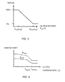
- Figure 3 is a diagram of various clutch energies and how they are rated.
- the system comprises also a rating unit 5 adapted to rating the clutch wear on the basis of said result and generating a rating signal Sg which indicates said rating. The driver's behaviour is then scored on the basis of the calculated energy E slip lost through the clutch. A very large amount of clutch energy generated results in a low rating, and a small amount of clutch energy generated a high rating.
- the rating scale in Figure 3 runs from 0 to 100% but other scales, e.g. 0 to 10, would be equally possible.
- the system further comprises an indicating unit 6 adapted to feeding the rating back to the driver.
- the indicating unit may for example be a display in the vehicle's instrument panel which shows the vehicle's ratings in the form of numerals or symbols.
- the system comprises a time unit 7 adapted to monitoring the driver's use of the clutch control by detecting a slip period t slip which is the time the driver takes to release the clutch from a disconnected state to a connected state.
- a slip period t slip which is the time the driver takes to release the clutch from a disconnected state to a connected state.
- pedal sensors may monitor the clutch pedal and detect its position in terms of closed and open.
- the comparison unit 4 is adapted to determining said limits for the clutch energy E slip with respect to the temperature of the clutch. This makes it possible to determine the clutch temperature limits within which the vehicle should be set in motion. Temperature sensors in the clutch may be avoided by using an estimate of the clutch temperature.
- Figure 4 illustrates an example of energy limits E HIGH and E LOW determined as a function of the clutch temperature.
- the temperature in the clutch may be determined as follows.
- the material of the clutch may be divided into two kinds, viz. 1: clutch disc and 2: surrounding material (flywheel, clutch housing, air, etc.).
- the clutch disc is assumed to absorb heat when slipping and then transfer it to surrounding material which itself gives off heat to the surroundings. This is illustrated in Figure 6 , in which the arrows indicate the direction of heat movement.
- k is a constant for the material, A the area of the disc and d the thickness of the disc.
- the thermal capacity i.e.
- m the weight of the material
- c the thermal capacity.
- k absorb is estimated by measuring the temperature increase when a given amount of energy is quickly supplied.
- the k conduct is estimated by measuring the cooling time for a component when k absorb is already known.
- the ambient temperature T ambient may for example be assumed to be a weighted average of engine temperature and air temperature. Cooling at higher speeds may also be taken into account.
- the system comprises a first monitoring unit 8 adapted to determining the temperature of the clutch and to generating a signal to the driver that the temperature in the clutch is high, if the vehicle has come to a halt and the temperature exceeds a predetermined threshold value.
- T critical a very low gear is required to meet the wear requirements.
- the system comprises a second monitoring unit 9 adapted to detecting settings of the gearbox, and if it is in a high gear, the vehicle is stationary and the driver releases the brake pedal, the monitoring unit 9 is adapted to generating a signal to the driver that a high gear is set.
- an expected scenario is that acceleration will follow. The driver may thus be made aware that the vehicle is about to move off in too high a gear, enabling him/her to downshift in time.
- the monitoring unit 9 is preferably adapted to monitoring whether the vehicle is stationary and to receiving signals from a sensor which monitors the position of the brake pedal.
- the monitoring unit 9 is adapted to detecting whether the gearbox is set in the high-speed or the low-speed section. If it finds that the gearbox is set in the high-speed section, the vehicle is stationary and the driver releases the brake pedal, the monitoring unit 9 according to this embodiment is adapted to generating a signal to the driver that a gear in the high-speed section is set. The risk that the driver might move off with the gear set in the high-speed section can thus be reduced.
- the system comprises according to an embodiment an identifying unit adapted to identifying what the driver has done wrong, by analysing the situation which has arisen.
- M takeoff F takeoff ⁇ r wheel i rear_axle ⁇ i gear ⁇ ⁇ gear ⁇ ⁇ axle , in which r wheel is wheel radius, i rear _ axle the ratio of the rear axle, i gear the ratio of the initial gear, ⁇ gear and ⁇ axle the respective efficiencies of the initial gear and the axle.
- the identifying unit 10 is thus adapted to calculating the engine torque M takeoff which was required to accelerate the vehicle for an initial distance d takeoff .M takeoff is then compared with at least one predetermined value M max of the engine torque, and if M takeoff exceeds a M max an indicating signal is generated to the driver that the vehicle's initial gear was too high when moving off. A limit is thus set for the engine torque which is acceptable when setting the vehicle in motion. The signal may include tips to the driver for improving his/her behaviour. If M takeoff was too high, the driver is reminded that this was so. He/she thus gradually learns which initial gears are appropriate to different road gradients and different loads. This reminder is not given if the lowest gear is already being used.
- the identifying unit 10 is adapted to comparing the time t slip with at least one predetermined time value t max , and if t slip exceeds t max an indicating signal is generated to the driver that the time taken to release the clutch pedal was too long. He/she may thus be made aware that the time taken to release the clutch was too long.
- the signal may include tips to the driver for improving his/her driving behaviour by being reminded to release the clutch more quickly moving off.
- the identifying unit 10 is adapted to comparing the engine's speed n eng when the vehicle is being set in motion with at least one predetermined engine speed value n max and, if n eng exceeds n max , to generating an indicating signal to the driver that the engine speed was too high when moving off.
- the signal may include tips for improving his/her driving behaviour by being reminded to keep the engine speed down when releasing the clutch.
- the invention comprises also a method for assessing a driver's wear of a friction clutch.
- the method comprises a first step S 1 of determining a value of the clutch energy E slip during a slip period, depending on the power output P eng and the clutch slip s.
- E slip is determined by using equations (1) to (7) set out above.
- a second step S2 generates an energy signal which indicates said value of E slip .
- a third step S3 then compares the calculated value of the clutch energy E slip with limits for the clutch energy. This is illustrated in Figure 3 .
- a fourth step S4 generates a comparison signal which indicates the result of said comparison.
- a fifth step S5 rates the clutch wear on the basis of said result.
- a sixth step S6 generates a rating signal which indicates said rating.
- a seventh step S7 feeds the rating back to the driver. He/she is thus made aware of how well he/she has used the clutch as regards wear.
- the method comprises determining said limits for the clutch energy E slip with respect to the temperature of the clutch.
- An example of relationships between the clutch temperature and limits for the clutch energy appears in Figure 4 . If the clutch temperature is high, the limits for the clutch energy will be low.
- the method comprises monitoring the driver's use of the clutch control by detecting a slip period t slip as an amount of time which the driver takes to release the clutch from a disconnected state to a connected state. Only the energy used during the slip period is thus taken into account in the assessment.
- the method comprises, according to an embodiment, detecting settings of the gearbox 2. If the gearbox is set in a high gear, the vehicle is stationary and the driver releases the brake pedal, a signal is then generated to him/her that a high gear is set. The driver may thus be reminded to switch to low gear if he/she forgets to do so before setting the vehicle in motion. He/she then avoids moving off in too high a gear which would result in greater clutch wear. If the gearbox is divided into high-speed and low-speed sections, this setting may also be detected and the driver be warned if too high a gear is set.
- the method comprises determining the temperature of the clutch 1 and generating a signal to the driver that the temperature in the clutch 1 is high, if the vehicle has come to a halt and the temperature exceeds a predetermined threshold value.
- the driver may thus be made aware that the clutch temperature is too high and that a lower gear should be set for the next move-off.
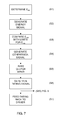
- the method comprises, according to an embodiment, doing an evaluation according to the method steps of the flowchart in Figure 8 .
- This identification is based on a rating signal generated at step S6 in Figure 7 .
- the rating is evaluated at step S80, and if it is poor, the identification of what has caused the poor rating begins.
- a poor rating may for example be within the range 1-5 on a scale of 1-10.
- Step S81 identifies whether too high an initial gear has been used. Identification of too high an initial gear is done, according to an embodiment, by calculating the engine torque M takeoff which was required to accelerate the vehicle for an initial distance d takeoff and by comparing M takeoff with at least one predetermined value M max of the engine torque.
- Step S82 identifies whether M takeoff exceeds M max , in which case a step S800 generates a signal to the driver that the vehicle's initial gear was too high when moving off.
- M takeoff may be determined by means of equations (14) to (16) above. The driver may thus be made aware that he/she used too high an initial gear.
- Step S83 identifies whether the poor rating was due to too high an engine speed when moving off. This is done according to an embodiment by comparing the engine's speed n eng during move-off with at least one predetermined engine speed value n max. Step S84 identifies whether n eng exceeds n max , in which case a step S800 generates an indicating signal to the driver that the engine speed was too high when moving off. The driver may thus be made aware that he/she used too high an engine speed when setting the vehicle in motion.
- Step S85 identifies whether the poor rating was due to the driver having taken too much time to release the clutch when setting the vehicle in motion. This is done according to an embodiment by comparing the time t slip with at least one predetermined time value t max. The next step S86 identifies whether t slip exceeds t max , in which case a step S800 generates a signal to the driver that the time taken to release the clutch pedal was too long. The driver may thus be made aware of how good he/she is at releasing the clutch as regards wear, and may be encouraged to reduce the time taken.
- the above embodiments may be effected in different sequences and need not be confined to the sequence in Figure 8 . It is also possible to indicate to the driver only one reason for poor ratings, thus stopping at the positive judgement arising from the first identification of fault. If there are two or more reasons for poor ratings, they may of course be communicated to the driver all together.
- the indicating signal to the driver may also contain tips on how to improve his/her driving behaviour. Tips from the various embodiments may for example be presented in order of priority or alternatively only the tip regarded as most important may be presented to the driver.
- the invention comprises also a computer programme product comprising programme instructions for enabling a computer system in a vehicle to perform the steps according to the above method when those instructions are run on said computer system.
- the invention comprises also a computer programme product in which the programme instructions are stored on a medium which can be read by a computer system.
Abstract
Description
- The present invention relates to assessment of wear in a clutch of a vehicle and particularly the driver's wear of a friction clutch according to the introduction to the independent claims.
- The driver's influence on vehicle wear is often considerable. Clutch wear is very often driver-related. In particular, the move-off sequence may wear the clutch when the driver does not act correctly, and also when heavy loads occur.
- A clutch in a motor vehicle with manual gear changing is fitted between the engine and the gearbox to convey the energy from the engine to the propeller shaft. The commonest type of clutch used in vehicles is the friction clutch. It comprises one or more discs with friction linings which are pressed against a flywheel by a pressure plate, resulting in direct drive between engine and gearbox when the vehicle is running. Pressing the clutch pedal down reduces progressively the pressure exerted on the disc by the pressure plate, causing the clutch to begin to slip. When the pedal is fully depressed, the engine is disconnected from the gearbox. The transfer of force between pedal and clutch may be mechanical, hydraulic or semi-hydraulic.
- Particularly in heavy vehicles, clutch wear is a problem because the clutch is subject to large forces. The driver of a heavy vehicle sometimes races the engine before setting the vehicle in motion, in an attempt to avoid the vehicle generally having too little power to move off uphill, or to avoid its rolling backwards. However, moving off at high engine speed entails great risk of clutch wear.
- As clutch replacement may cost the vehicle owner a great deal of money, there is an incentive to train the driver in good behaviour.
-
EP1482196 describes a method for calculating the wear on a friction clutch in a vehicle. Various kinds of operating data are saved for use on the occasion of, for example, servicing. -
DE102008007559 describes a monitoring device which uses sensors for determining whether incorrect gears are used relative to torque. Incorrect gears are indicated to the driver by a warning signal. -
W02010020520 describes a method for detecting clutch wear by comparing an actual pattern with a desired pattern on the clutch actuators. -
W00172546 - The above systems and methods identify only high clutch wear. They therefore cannot identify what the driver has done wrong, with a view to being able to help him/her to achieve better behaviour. Nor is there generally any feedback from setting the vehicle in motion well, which is also an important part of the learning process. No account is taken of occasions when the vehicle is set in motion many times in succession, which contributes to raised temperatures in the clutch discs and consequently increased wear.
- The object of the present invention is to propose an improved method for reducing clutch wear in vehicles.
- The object described above is achieved by a system for assessing a driver's wear of a friction clutch situated between a gearbox and an engine in a vehicle. The system comprises a calculation unit adapted to determining a value of the clutch energy Eslip during a slip period, depending on the vehicle's power output Peng and the clutch slip s, and to generating an energy signal which indicates said value of Eslip, a comparison unit adapted to comparing the calculated value of the clutch energy E,slipwith limits for the clutch energy and to generating a comparison signal Sc which indicates the result of said comparison, a rating unit adapted to rating clutch wear on the basis of said result and to generating a rating signal Sg which indicates said rating, and an indicating unit adapted to feeding the rating back to the driver.
- According to another aspect, the object is achieved by a method for assessing a driver's wear of a friction clutch which comprises:
- determining a value of the clutch energy Eslip during a slip period, depending on the vehicle's power output Peng and the clutch slip s, and generating an energy signal which indicates said value of Eslip;
- comparing the calculated value of the clutch energy Eslip with limits for the clutch energy, and generating a comparison signal which indicates the result of said comparison;
- rating the clutch wear on the basis of said result and generating a rating signal which indicates said rating; and
- feeding the rating back to the driver.
- In this way the driver may receive feedback about his/her clutch behaviour, particularly when setting the vehicle in motion, in order thereby to learn to handle the move-off sequence well. He/she may also, even before starting to set the vehicle in motion, be given tips or reminders to help him/her to avoid unnecessary clutch wear. This will result in less clutch wear and no need for the clutch to be changed as often, thereby saving money.
- The assessment of clutch wear is done by calculating the energy lost through the clutch when, for example, the vehicle is being set in motion. Calculating this energy may sometimes be difficult if there are no sensors to show which gear the driver chose. Calculations of the clutch energy may therefore be completed when the process of setting the vehicle in motion has ended and the initial gear can be determined by estimation.
- Preferred embodiments are described in the dependent claims and the detailed description.
- The invention is described below with reference to the attached drawings, in which:
-
Figure 1 is a schematic diagram of a friction clutch. -
Figure 2 is a block diagram of the system according to an embodiment of the invention. -
Figure 3 depicts an example of clutch wear rating. -
Figure 4 depicts an example of energy limits EHIGH and ELOW as a function of clutch temperature. At Twarn the driver is given a reminder to use a lower initial gear than normal. At Tenticat a very low gear is needed to meet wear requirements. -
Figure 5 illustrates parameters used for identifying initial gears which are too high. -
Figure 6 is a schematic diagram of a friction clutch and the pattern of heat flow. -
Figure 7 is a flowchart of a method according to an embodiment of the invention. -
Figure 8 is a flowchart of a method according to a further embodiment of the invention. -
Figure 1 is a schematic diagram of afriction clutch 1 and nearby parts. The engine speed neng and power output Peng are conveyed via theclutch 1 and thegearbox 2 to adriveshaft 11 which transmits a driveshaft speed np to the vehicle's wheels. The gear set for the gearbox at the time is illustrated as igear. Thefriction clutch 1 comprises one or more discs with friction linings which are pressed against a steel plate, e.g. by powerful springs and a pressure plate, resulting in direct drive between engine and gearbox when the vehicle is running. Pressing the clutch pedal down reduces progressively the pressure exerted on the disc by the pressure plate, causing the clutch to begin to slip. The slip results in a speed difference between the parts of the clutch which are pressed together, here the pressure plate and the disc. This means that the parts wear one another by friction. When the clutch pedal is fully depressed, the engine is almost entirely disconnected from the gearbox. -
Figure 2 is a block diagram of a system for assessing a driver's wear of afriction clutch 1. The system comprises acalculation unit 3 adapted to determining a value of the clutch energy Eslip generated during a slip period, depending on the power output Peng and the clutch slip s, and to generating an energy signal which indicates said value of Eslip. The clutch energy may be determined by using the equations set out below. The instantaneous gear ratio between engine and driveshaft, including the clutch, is calculated by the equation
- The ratio in the initial gear igear may be unknown when the vehicle is being set in motion. The instantaneous slip s may be calculated by the equation

- The power output conveyed to the clutch then becomes

- When the clutch slips, the clutch energy Eslip is arrived at by the calculations

in which igear is still unknown. As igear is unknown, two energies are calculated during the period when the driver is sliding the clutch:

- According to this embodiment, the
calculation unit 3 is therefore adapted to determining the value of the clutch energy Eslip, which comprises integrating the value of the power output Peng, and the power output Peng divided by the gear ratio itransf during the slip period. - When moving off is completed and the vehicle is travelling, the initial gear can be estimated. The result is a value of gear which makes it possible for the calculation to be completed by the equation

- The system further comprises a
comparison unit 4 adapted to comparing the calculated value of the clutch energy Eslip with limits for the clutch energy, and to generating a comparison signal Sc which indicates the result of said comparison.Figure 3 is a diagram of various clutch energies and how they are rated. The system comprises also arating unit 5 adapted to rating the clutch wear on the basis of said result and generating a rating signal Sg which indicates said rating. The driver's behaviour is then scored on the basis of the calculated energy Eslip lost through the clutch. A very large amount of clutch energy generated results in a low rating, and a small amount of clutch energy generated a high rating. The rating scale inFigure 3 runs from 0 to 100% but other scales, e.g. 0 to 10, would be equally possible. The system further comprises an indicatingunit 6 adapted to feeding the rating back to the driver. The indicating unit may for example be a display in the vehicle's instrument panel which shows the vehicle's ratings in the form of numerals or symbols. - According to an embodiment, the system comprises a
time unit 7 adapted to monitoring the driver's use of the clutch control by detecting a slip period tslip which is the time the driver takes to release the clutch from a disconnected state to a connected state. For example, pedal sensors may monitor the clutch pedal and detect its position in terms of closed and open. - To cater for wear being worse when the temperature in the clutch is high, the
comparison unit 4 according to an embodiment is adapted to determining said limits for the clutch energy Eslip with respect to the temperature of the clutch. This makes it possible to determine the clutch temperature limits within which the vehicle should be set in motion. Temperature sensors in the clutch may be avoided by using an estimate of the clutch temperature.Figure 4 illustrates an example of energy limits EHIGH and ELOW determined as a function of the clutch temperature. - The temperature in the clutch may be determined as follows. The material of the clutch may be divided into two kinds, viz. 1: clutch disc and 2: surrounding material (flywheel, clutch housing, air, etc.). The clutch disc is assumed to absorb heat when slipping and then transfer it to surrounding material which itself gives off heat to the surroundings. This is illustrated in
Figure 6 , in which the arrows indicate the direction of heat movement. Underlying formulae used for heat flow and thermal capacity are
which thus indicates the heat flow ΔQ at the temperature difference ΔT. k is a constant for the material, A the area of the disc and d the thickness of the disc. The thermal capacity, i.e. the energy Q supplied to the disc, is calculated as
in which m is the weight of the material and c the thermal capacity. As the material constants are unknown, they are estimated by actual measurements of energy absorption and cooling. The calculations may therefore be shortened to ΔQ = kconduct ΔT for heat flow and Q = kabsorbΔT for thermal capacity for the given components. kabsorb is estimated by measuring the temperature increase when a given amount of energy is quickly supplied. The kconduct is estimated by measuring the cooling time for a component when kabsorb is already known. - The energy supplied to the disc during clutch slip is assumed to result in a heat increase corresponding to

in which kabsorb-disc thus denotes a constant for the heat absorption in the disc. The heat flow from disc to surrounding material is assumed to be
and cooling of surrounding material is calculated as
- The temperatures then change during cooling according to the equations


- If not measured, the ambient temperature Tambient may for example be assumed to be a weighted average of engine temperature and air temperature. Cooling at higher speeds may also be taken into account.
- Where the vehicle is repeatedly set in motion, the temperature in the clutch is calculated on the basis of the energy supplied Eslip arrived at by the above calculations. On the basis of material constants and simple assumptions about cooling of the material, it is therefore possible to estimate the temperature, see calculations above. According to an embodiment, the system comprises a
first monitoring unit 8 adapted to determining the temperature of the clutch and to generating a signal to the driver that the temperature in the clutch is high, if the vehicle has come to a halt and the temperature exceeds a predetermined threshold value. When the temperature of the disc Tdisc reaches a critical level Twarn and the driver stops, he/she is thus given a reminder to be aware that the temperature in the clutch is high and that a lower initial gear than normal may therefore need to be used. At Tcritical a very low gear is required to meet the wear requirements. - On most trucks with manual gear changing it is possible on the basis of only three or four gear positions to have access to between eight and twelve gears. This is made possible inter alia by a range gear which divides the gears into a high-speed section and a low-speed section. When an inexperienced driver has driven for a while at high speed and then brings the vehicle to a halt, he/she may well forget to switch to low range before setting the vehicle in motion again. Moving off in high range contributes to clutch wear. The same problem may also arise with a gearbox in an ordinary vehicle which has no range gears but only the division between low and high gears. This division may vary depending on the vehicle's current situation. When setting it in motion, however, a low gear is preferable. To prevent wear, the system according to an embodiment comprises a
second monitoring unit 9 adapted to detecting settings of the gearbox, and if it is in a high gear, the vehicle is stationary and the driver releases the brake pedal, themonitoring unit 9 is adapted to generating a signal to the driver that a high gear is set. When the brake pedal is released, an expected scenario is that acceleration will follow. The driver may thus be made aware that the vehicle is about to move off in too high a gear, enabling him/her to downshift in time. Themonitoring unit 9 is preferably adapted to monitoring whether the vehicle is stationary and to receiving signals from a sensor which monitors the position of the brake pedal. If the gears are divided into respective high-speed and low-speed sections, themonitoring unit 9 according to an embodiment is adapted to detecting whether the gearbox is set in the high-speed or the low-speed section. If it finds that the gearbox is set in the high-speed section, the vehicle is stationary and the driver releases the brake pedal, themonitoring unit 9 according to this embodiment is adapted to generating a signal to the driver that a gear in the high-speed section is set. The risk that the driver might move off with the gear set in the high-speed section can thus be reduced. - According to an embodiment, when clutch wear has been assessed and the energy to the clutch has been calculated, an attempt is made to identify what the driver has done wrong, to help him/her to be able to achieve better behaviour. To this end, the system comprises according to an embodiment an identifying unit adapted to identifying what the driver has done wrong, by analysing the situation which has arisen.
- To identify if the driver has used too high an initial gear, the energy Eslip lost to the clutch when the vehicle was being set in motion is calculated. The remaining energy is used instead to accelerate the vehicle and counteract any gravitational force. During a moving-off process, the energy used to set the vehicle in motion and accelerate it is therefore calculated. The moving-off period is the same here as a clutch slip period. This energy is then used to calculate a force which was required to accelerate the vehicle as

in which dtakeoff is the moving-off distance and Etakeoffthe remaining energy. Ftakeoff and the dtakeoff are illustrated inFigure 5 . Etakeoff is calculated by
in which E1 is arrived at by equation (5). - To then identify whether the initial gear was or was not low enough, the engine torque Mtakeoff which was required to accelerate the vehicle initially is calculated as

in which rwheel is wheel radius, irear_axle the ratio of the rear axle, igear the ratio of the initial gear, ηgear and ηaxle the respective efficiencies of the initial gear and the axle. - The identifying
unit 10 is thus adapted to calculating the engine torque Mtakeoff which was required to accelerate the vehicle for an initial distance dtakeoff.Mtakeoff is then compared with at least one predetermined value Mmax of the engine torque, and if Mtakeoff exceeds a Mmax an indicating signal is generated to the driver that the vehicle's initial gear was too high when moving off. A limit is thus set for the engine torque which is acceptable when setting the vehicle in motion. The signal may include tips to the driver for improving his/her behaviour. If Mtakeoffwas too high, the driver is reminded that this was so. He/she thus gradually learns which initial gears are appropriate to different road gradients and different loads. This reminder is not given if the lowest gear is already being used. - According to an embodiment, the identifying
unit 10 is adapted to comparing the time tslip with at least one predetermined time value tmax, and if tslip exceeds tmax an indicating signal is generated to the driver that the time taken to release the clutch pedal was too long. He/she may thus be made aware that the time taken to release the clutch was too long. The signal may include tips to the driver for improving his/her driving behaviour by being reminded to release the clutch more quickly moving off. - According to another embodiment, the identifying
unit 10 is adapted to comparing the engine's speed neng when the vehicle is being set in motion with at least one predetermined engine speed value nmax and, if neng exceeds nmax, to generating an indicating signal to the driver that the engine speed was too high when moving off. The signal may include tips for improving his/her driving behaviour by being reminded to keep the engine speed down when releasing the clutch. - The invention comprises also a method for assessing a driver's wear of a friction clutch. The method will now be explained with reference to the flowchart in
Figure 7 . The method comprises afirst step S 1 of determining a value of the clutch energy Eslip during a slip period, depending on the power output Peng and the clutch slip s. Eslip is determined by using equations (1) to (7) set out above. A second step S2 generates an energy signal which indicates said value of Eslip. A third step S3 then compares the calculated value of the clutch energy Eslipwith limits for the clutch energy. This is illustrated inFigure 3 . A fourth step S4 generates a comparison signal which indicates the result of said comparison. A fifth step S5 rates the clutch wear on the basis of said result. This is also illustrated inFigure 3 in the form of a rating between 0 and 100%. A sixth step S6 generates a rating signal which indicates said rating. A seventh step S7 feeds the rating back to the driver. He/she is thus made aware of how well he/she has used the clutch as regards wear. - According to an embodiment, the method comprises determining said limits for the clutch energy Eslip with respect to the temperature of the clutch. An example of relationships between the clutch temperature and limits for the clutch energy appears in
Figure 4 . If the clutch temperature is high, the limits for the clutch energy will be low. - According to another embodiment, the method comprises monitoring the driver's use of the clutch control by detecting a slip period tslip as an amount of time which the driver takes to release the clutch from a disconnected state to a connected state. Only the energy used during the slip period is thus taken into account in the assessment.
- To avoid the driver forgetting to change gear when moving off, the method comprises, according to an embodiment, detecting settings of the
gearbox 2. If the gearbox is set in a high gear, the vehicle is stationary and the driver releases the brake pedal, a signal is then generated to him/her that a high gear is set. The driver may thus be reminded to switch to low gear if he/she forgets to do so before setting the vehicle in motion. He/she then avoids moving off in too high a gear which would result in greater clutch wear. If the gearbox is divided into high-speed and low-speed sections, this setting may also be detected and the driver be warned if too high a gear is set. - According to a further embodiment, the method comprises determining the temperature of the
clutch 1 and generating a signal to the driver that the temperature in theclutch 1 is high, if the vehicle has come to a halt and the temperature exceeds a predetermined threshold value. The driver may thus be made aware that the clutch temperature is too high and that a lower gear should be set for the next move-off. - To be able to identify what the driver has done wrong, the method comprises, according to an embodiment, doing an evaluation according to the method steps of the flowchart in
Figure 8 . This identification is based on a rating signal generated at step S6 inFigure 7 . The rating is evaluated at step S80, and if it is poor, the identification of what has caused the poor rating begins. A poor rating may for example be within the range 1-5 on a scale of 1-10. Step S81 identifies whether too high an initial gear has been used. Identification of too high an initial gear is done, according to an embodiment, by calculating the engine torque Mtakeoff which was required to accelerate the vehicle for an initial distance dtakeoff and by comparing Mtakeoffwith at least one predetermined value Mmax of the engine torque. Step S82 identifies whether Mtakeoff exceeds Mmax, in which case a step S800 generates a signal to the driver that the vehicle's initial gear was too high when moving off. Mtakeoff may be determined by means of equations (14) to (16) above. The driver may thus be made aware that he/she used too high an initial gear. - Step S83 identifies whether the poor rating was due to too high an engine speed when moving off. This is done according to an embodiment by comparing the engine's speed neng during move-off with at least one predetermined engine speed value nmax. Step S84 identifies whether neng exceeds nmax, in which case a step S800 generates an indicating signal to the driver that the engine speed was too high when moving off. The driver may thus be made aware that he/she used too high an engine speed when setting the vehicle in motion.
- Step S85 identifies whether the poor rating was due to the driver having taken too much time to release the clutch when setting the vehicle in motion. This is done according to an embodiment by comparing the time tslip with at least one predetermined time value tmax. The next step S86 identifies whether tslip exceeds tmax, in which case a step S800 generates a signal to the driver that the time taken to release the clutch pedal was too long. The driver may thus be made aware of how good he/she is at releasing the clutch as regards wear, and may be encouraged to reduce the time taken.
- The above embodiments may be effected in different sequences and need not be confined to the sequence in
Figure 8 . It is also possible to indicate to the driver only one reason for poor ratings, thus stopping at the positive judgement arising from the first identification of fault. If there are two or more reasons for poor ratings, they may of course be communicated to the driver all together. The indicating signal to the driver may also contain tips on how to improve his/her driving behaviour. Tips from the various embodiments may for example be presented in order of priority or alternatively only the tip regarded as most important may be presented to the driver. - The invention comprises also a computer programme product comprising programme instructions for enabling a computer system in a vehicle to perform the steps according to the above method when those instructions are run on said computer system. The invention comprises also a computer programme product in which the programme instructions are stored on a medium which can be read by a computer system.
- The present invention is not restricted to the embodiments described above. Sundry alternatives, modifications and equivalents may be used. The aforesaid embodiments therefore do not limit the invention's scope which is defined by the attached claims.
Claims (22)
- A system for assessing a driver's wear of a friction clutch (1) situated between a gearbox (2) and an engine in a vehicle, comprising:- a calculation unit (3) adapted to determining a value of the clutch energy Eslip during a slip period, depending on the vehicle's power output Peng and the clutch slip s, and to generating an energy signal which indicates said value of Eslip; c h a r a c t e r i s e d i n that the system comprises- a comparison unit (4) adapted to comparing the calculated value of the clutch energy Eslip with limits for the clutch energy, and to generating a comparison signal Sc which indicates the result of said comparison;- a rating unit (5) adapted to rating the clutch wear on the basis of said result and to generating a rating signal Sg which indicates said rating; and- an indicating unit (6) adapted to feeding the rating back to the driver.
- A system according to claim 1, whereby the comparison unit (4) is adapted to determining said limits for the clutch energy Eslip with respect to the temperature of the clutch.
- A system according to claim 1 or 2, comprising a time unit (7) adapted to monitoring the driver's use of the clutch control by detecting a slip period tslip as the time the driver takes to release the clutch from a disconnected state to a connected state.
- A system according to any one of the foregoing claims, whereby determining the value of the clutch energy Eslip comprises integrating the value of the power output Peng and the power output Peng divided by the gear ratio itransf.
- A system according to any one of the foregoing claims, comprising a first monitoring unit (8) adapted to determining the temperature of the clutch and to generating an indicating signal to the driver that the temperature in the clutch is high, if the vehicle has come to a halt and the temperature exceeds a predetermined threshold value.
- A system according to any one of the foregoing claims, comprising a second monitoring unit (9) adapted to detecting settings of the gearbox and, if the gearbox is set to a high gear, the vehicle is stationary and the driver releases the brake pedal, to generating a signal to him/her that a high gear is set.
- A system according to any one of the foregoing claims, comprising an identifying unit (10) adapted to calculating the engine torque Mtakeoff which was required to accelerate the vehicle for an initial distance dtakeoff, to comparing Mtakeoff with at least one predetermined value Mmax of the engine torque and, if Mtakeoff exceeds Mmax, to generating a signal to the driver that the initial gear was too high when moving off.
- A system according to claim 3, comprising an identifying unit (10) adapted to comparing the time tslip with at least one predetermined time value tmax and, if tslip exceeds tmax, to generating an indicating signal to the driver that the time taken to release the clutch pedal was too long.
- A system according to any one of the foregoing claims, comprising an identifying unit (10) adapted to comparing the engine's speed neng when the vehicle is being set in motion with at least one predetermined engine speed value nmax and, if neng exceeds nmax, to generating a signal to the driver that the engine speed was too high when setting the vehicle in motion.
- A system according to any one of claims 7 to 9, comprising said indicating signal to the driver containing tips for improving his/her driving behaviour.
- A method for assessing a driver's wear of a friction clutch (1) situated between a gearbox (2) and an engine in a vehicle, comprising:- determining a value of the clutch energy Eslip during a slip period, depending on the vehicle's power output Peng and the clutch slip s, and generating an energy signal which indicates said value of Eslip;- comparing the calculated value of the clutch energy Eslip with limits for the clutch energy, and generating a comparison signal which indicates the result of said comparison;- rating the clutch wear on the basis of said result and generating a rating signal which indicates said rating; and- feeding the rating back to the driver.
- A method according to claim 11, comprising determining said limits for the clutch energy Eslip with respect to the temperature of the clutch.
- A method according to claim 11 or 12, comprising determining the driver's use of the clutch control by detecting a slip period tslip as the time the driver takes to release the clutch from a disconnected state to a connected state.
- A method according to any one of claims 11 to 13 whereby determining the value of the clutch energy Eslip comprises integrating the value of the power output Peng and the power output Peng divided by the gear ratio itransf.
- A method according to any one of claims 11 to 14, comprising detecting settings of the gearbox (2) and, if the gearbox (2) is set to a high gear, the vehicle is stationary and the driver releases the brake pedal, generating a signal to him/her that a high gear is set.
- A method according to any one of claims 11 to 15, comprising determining the temperature of the clutch (1) and to generating an indicating signal to the driver that the temperature in the clutch (1) is high, if the vehicle has come to a halt and the temperature exceeds a predetermined threshold value.
- A method according to any one of claims 11 to 15, comprising calculating the engine torque Mtakeoff which was required to accelerate the vehicle for an initial distance dtakeoff, comparing Mtakeoff, with at least one predetermined value Mmax of the engine torque and, if Mtakeoff exceeds Mmax, generating a signal to the driver that the initial gear was too high when moving off.
- A method according to claim 13, comprising comparing the time tslip with at least one predetermined time value tmax and, if tslip exceeds tmax, generating a signal to the driver that the time taken to release the clutch pedal was too long.
- A method according to any one of claims 11 to 18, comprising comparing the engine's speed neng when the vehicle is being set in motion with at least predetermined engine speed value nmax and, if neng exceeds nmax, generating a signal to the driver that the engine speed was too high when setting the vehicle in motion.
- A method according to any one of claims 17 to 19, whereby said indicating signal to the driver contains tips for improving his/her driving behaviour.
- A computer programme product comprising programme instructions for enabling a computer system in a vehicle to perform the steps according to the method of any of claims 11 to 20 when those instructions are run on said computer system.
- A computer programme product according to claim 21, in which the programme instructions are stored on a medium which can be read by a computer system.
Applications Claiming Priority (1)
| Application Number | Priority Date | Filing Date | Title |
|---|---|---|---|
| SE1051274A SE535427C2 (en) | 2010-12-02 | 2010-12-02 | Method and system for assessing coupling wear |
Publications (3)
| Publication Number | Publication Date |
|---|---|
| EP2461064A2 true EP2461064A2 (en) | 2012-06-06 |
| EP2461064A3 EP2461064A3 (en) | 2012-11-14 |
| EP2461064B1 EP2461064B1 (en) | 2014-07-30 |
Family
ID=45065754
Family Applications (1)
| Application Number | Title | Priority Date | Filing Date |
|---|---|---|---|
| EP11190348.0A Active EP2461064B1 (en) | 2010-12-02 | 2011-11-23 | Method and system for assessment of clutch wear |
Country Status (3)
| Country | Link |
|---|---|
| EP (1) | EP2461064B1 (en) |
| BR (1) | BRPI1105056B1 (en) |
| SE (1) | SE535427C2 (en) |
Cited By (3)
| Publication number | Priority date | Publication date | Assignee | Title |
|---|---|---|---|---|
| WO2018233757A1 (en) * | 2017-06-21 | 2018-12-27 | Schaeffler Technologies AG & Co. KG | Method for the correct determination of friction energy arising in a clutch as a vehicle fitted with a manual gearbox pulls away |
| CN110406524A (en) * | 2018-04-26 | 2019-11-05 | 康明斯公司 | Clutch abuses indicator |
| CN113859245A (en) * | 2021-09-13 | 2021-12-31 | 东风汽车集团股份有限公司 | Method, device, medium and equipment for determining friction loss of clutch |
Citations (4)
| Publication number | Priority date | Publication date | Assignee | Title |
|---|---|---|---|---|
| WO2001072546A1 (en) | 2000-03-27 | 2001-10-04 | Scania Cv Ab (Publ) | Method and apparatus for indication of clutch slip |
| EP1482196A1 (en) | 2003-05-30 | 2004-12-01 | MAN Nutzfahrzeuge Aktiengesellschaft | Method of calculating the wear of a friction clutch situated between a combustion engine and a gearbox in a commercial vehicle |
| DE102008007559A1 (en) | 2008-02-05 | 2009-01-29 | Daimler Ag | Monitoring device for monitoring starting process of motor vehicle, has set of evaluation and signaling devices determining whether vehicle drives in higher gear and transmitting warning signal when vehicle does not drive in gear |
| WO2010020520A1 (en) | 2008-08-22 | 2010-02-25 | Robert Bosch Gmbh | Method for detecting a wear of a motor disconnect clutch |
Family Cites Families (12)
| Publication number | Priority date | Publication date | Assignee | Title |
|---|---|---|---|---|
| DE19602006A1 (en) * | 1995-01-28 | 1996-08-01 | Luk Getriebe Systeme Gmbh | Torque transfer system, such as clutch, control system |
| DE19639296C1 (en) * | 1996-09-25 | 1998-04-02 | Daimler Benz Ag | Drive clutch for motor vehicle |
| WO2003087614A1 (en) * | 2002-04-10 | 2003-10-23 | Luk Lamellen Und Kupplungsbau Beteiligungs Kg | Device and method for monitoring a clutch |
| DE102004023581A1 (en) * | 2004-05-13 | 2005-12-08 | Adam Opel Ag | Clutch controlling method for motor vehicle gear, involves evaluating temperature of clutch and comparing temperature with temperature threshold value, where control unit is substitution strategy for starting vehicle |
| US8370037B2 (en) * | 2004-06-30 | 2013-02-05 | Schaeffler Technologies AG & Co. KG | Method for the protection of an automatically actuated clutch of a vehicle from overload |
| DE102005061080A1 (en) * | 2005-01-20 | 2006-07-27 | Luk Lamellen Und Kupplungsbau Beteiligungs Kg | Damage detection method of clutch, involves determining friction power introduced into friction surfaces of components, by slippage between torque-transferring components |
| DE102005026615A1 (en) * | 2005-06-09 | 2006-12-14 | Zf Friedrichshafen Ag | Method and apparatus for controlling an automated friction clutch between a motor and a transmission |
| DE102006037389A1 (en) * | 2006-08-10 | 2008-02-14 | Daimler Ag | Assessment of clutch energy dissipation on starting off, using a manual gearbox, takes the selected gear reduction for an assessment correction to prevent overheating |
| JP5232441B2 (en) * | 2007-10-30 | 2013-07-10 | 三菱重工業株式会社 | Clutch device alarm device |
| US8062178B2 (en) * | 2008-11-05 | 2011-11-22 | Ford Global Technologies, Llc | Temperature control of dual input clutch transmission |
| SE533138C2 (en) * | 2008-11-21 | 2010-07-06 | Scania Cv Abp | Gear Feedback System |
| SE0950384A1 (en) * | 2009-05-28 | 2010-11-29 | Scania Cv Ab | Method and system for displaying information related to how a vehicle is driven |
-
2010
- 2010-12-02 SE SE1051274A patent/SE535427C2/en unknown
-
2011
- 2011-11-23 EP EP11190348.0A patent/EP2461064B1/en active Active
- 2011-11-28 BR BRPI1105056-0A patent/BRPI1105056B1/en active IP Right Grant
Patent Citations (4)
| Publication number | Priority date | Publication date | Assignee | Title |
|---|---|---|---|---|
| WO2001072546A1 (en) | 2000-03-27 | 2001-10-04 | Scania Cv Ab (Publ) | Method and apparatus for indication of clutch slip |
| EP1482196A1 (en) | 2003-05-30 | 2004-12-01 | MAN Nutzfahrzeuge Aktiengesellschaft | Method of calculating the wear of a friction clutch situated between a combustion engine and a gearbox in a commercial vehicle |
| DE102008007559A1 (en) | 2008-02-05 | 2009-01-29 | Daimler Ag | Monitoring device for monitoring starting process of motor vehicle, has set of evaluation and signaling devices determining whether vehicle drives in higher gear and transmitting warning signal when vehicle does not drive in gear |
| WO2010020520A1 (en) | 2008-08-22 | 2010-02-25 | Robert Bosch Gmbh | Method for detecting a wear of a motor disconnect clutch |
Cited By (5)
| Publication number | Priority date | Publication date | Assignee | Title |
|---|---|---|---|---|
| WO2018233757A1 (en) * | 2017-06-21 | 2018-12-27 | Schaeffler Technologies AG & Co. KG | Method for the correct determination of friction energy arising in a clutch as a vehicle fitted with a manual gearbox pulls away |
| CN110651134A (en) * | 2017-06-21 | 2020-01-03 | 舍弗勒技术股份两合公司 | Method for the corrected determination of the friction energy generated in a clutch during a start of a vehicle having a manual transmission |
| CN110651134B (en) * | 2017-06-21 | 2021-04-02 | 舍弗勒技术股份两合公司 | Method for the corrected determination of the friction energy generated in a clutch during a start of a vehicle having a manual transmission |
| CN110406524A (en) * | 2018-04-26 | 2019-11-05 | 康明斯公司 | Clutch abuses indicator |
| CN113859245A (en) * | 2021-09-13 | 2021-12-31 | 东风汽车集团股份有限公司 | Method, device, medium and equipment for determining friction loss of clutch |
Also Published As
| Publication number | Publication date |
|---|---|
| SE1051274A1 (en) | 2012-06-03 |
| EP2461064B1 (en) | 2014-07-30 |
| EP2461064A3 (en) | 2012-11-14 |
| BRPI1105056A2 (en) | 2013-03-12 |
| SE535427C2 (en) | 2012-08-07 |
| BRPI1105056B1 (en) | 2021-05-11 |
Similar Documents
| Publication | Publication Date | Title |
|---|---|---|
| US5723779A (en) | System for determining residual life of friction clutch | |
| US8651256B2 (en) | Method and arrangement for determining the wear condition of a shifting clutch | |
| CN103802824A (en) | Method and system for learning operation of engine clutch of hybrid vehicle | |
| US20060154781A1 (en) | Process for operating an automatically actuated friction clutch and/or a transmission | |
| EP3042095B1 (en) | System and method to predict the remaining useful life of a clutch by coefficient of friction estimation | |
| US20120271523A1 (en) | Method for operating an automated parking brake in a motor vehicle | |
| SE1251304A1 (en) | Fuel consumption analysis in a vehicle | |
| CN103459876A (en) | Method for determining wet clutch temperature | |
| JP2004515402A (en) | Device for detecting the risk of aquaplaning occurring during the driving mode of a vehicle | |
| JP2010065637A (en) | Method and device for diagnosing degradation of lubricating oil in industrial vehicle | |
| JP2007271282A (en) | Vehicle weight detector for vehicle provided with fluid coupling | |
| JPH08303485A (en) | Remaining life judging device for multiple disc friction clutch | |
| EP2461064B1 (en) | Method and system for assessment of clutch wear | |
| CN101466961A (en) | Method and device for identifying a passive rolling moment of a motor vehicle | |
| US7603220B2 (en) | Method and system for detecting damage done to a clutch having at least two components that transfer torque by frictional engagement | |
| JP2010065795A (en) | Method and device for diagnosis of clutch failure of industrial vehicle | |
| US10245949B2 (en) | Method for operating a motor vehicle including an all-wheel drive that can be enabled and disabled by determining an angular acceleration of components, which are uncoupled when the all-wheel drive is disabled | |
| CN105782270A (en) | Real-time monitoring and controlling method for friction torque of dry clutch | |
| SE533139C2 (en) | System for determining the ability to predict braking | |
| US8838352B2 (en) | Method and device for selecting a starting gear in a vehicle | |
| EP2767817B1 (en) | Method and device and computer program and computer readable means for monitoring the wear of the clutch of a manual or of an automated manual transmission , in particular for heavy vehicles | |
| RU2561400C2 (en) | Method and system for assessment of behaviour of driver's braking | |
| CN108799360B (en) | Method for determining the condition of a clutch | |
| US20190077390A1 (en) | Energy based park brake end of life detection system and method | |
| US20190084574A1 (en) | Digital Clutch Gauge |
Legal Events
| Date | Code | Title | Description |
|---|---|---|---|
| PUAI | Public reference made under article 153(3) epc to a published international application that has entered the european phase |
Free format text: ORIGINAL CODE: 0009012 |
|
| AK | Designated contracting states |
Kind code of ref document: A2 Designated state(s): AL AT BE BG CH CY CZ DE DK EE ES FI FR GB GR HR HU IE IS IT LI LT LU LV MC MK MT NL NO PL PT RO RS SE SI SK SM TR |
|
| AX | Request for extension of the european patent |
Extension state: BA ME |
|
| PUAL | Search report despatched |
Free format text: ORIGINAL CODE: 0009013 |
|
| AK | Designated contracting states |
Kind code of ref document: A3 Designated state(s): AL AT BE BG CH CY CZ DE DK EE ES FI FR GB GR HR HU IE IS IT LI LT LU LV MC MK MT NL NO PL PT RO RS SE SI SK SM TR |
|
| AX | Request for extension of the european patent |
Extension state: BA ME |
|
| RIC1 | Information provided on ipc code assigned before grant |
Ipc: F16D 48/06 20060101AFI20121009BHEP |
|
| 17P | Request for examination filed |
Effective date: 20130514 |
|
| 17Q | First examination report despatched |
Effective date: 20130614 |
|
| GRAP | Despatch of communication of intention to grant a patent |
Free format text: ORIGINAL CODE: EPIDOSNIGR1 |
|
| INTG | Intention to grant announced |
Effective date: 20140416 |
|
| GRAS | Grant fee paid |
Free format text: ORIGINAL CODE: EPIDOSNIGR3 |
|
| GRAA | (expected) grant |
Free format text: ORIGINAL CODE: 0009210 |
|
| AK | Designated contracting states |
Kind code of ref document: B1 Designated state(s): AL AT BE BG CH CY CZ DE DK EE ES FI FR GB GR HR HU IE IS IT LI LT LU LV MC MK MT NL NO PL PT RO RS SE SI SK SM TR |
|
| REG | Reference to a national code |
Ref country code: GB Ref legal event code: FG4D |
|
| REG | Reference to a national code |
Ref country code: CH Ref legal event code: EP |
|
| REG | Reference to a national code |
Ref country code: AT Ref legal event code: REF Ref document number: 680143 Country of ref document: AT Kind code of ref document: T Effective date: 20140815 |
|
| REG | Reference to a national code |
Ref country code: IE Ref legal event code: FG4D |
|
| REG | Reference to a national code |
Ref country code: DE Ref legal event code: R096 Ref document number: 602011008692 Country of ref document: DE Effective date: 20140911 |
|
| REG | Reference to a national code |
Ref country code: AT Ref legal event code: MK05 Ref document number: 680143 Country of ref document: AT Kind code of ref document: T Effective date: 20140730 |
|
| REG | Reference to a national code |
Ref country code: NL Ref legal event code: VDEP Effective date: 20140730 |
|
| REG | Reference to a national code |
Ref country code: LT Ref legal event code: MG4D |
|
| PG25 | Lapsed in a contracting state [announced via postgrant information from national office to epo] |
Ref country code: NO Free format text: LAPSE BECAUSE OF FAILURE TO SUBMIT A TRANSLATION OF THE DESCRIPTION OR TO PAY THE FEE WITHIN THE PRESCRIBED TIME-LIMIT Effective date: 20141030 Ref country code: LT Free format text: LAPSE BECAUSE OF FAILURE TO SUBMIT A TRANSLATION OF THE DESCRIPTION OR TO PAY THE FEE WITHIN THE PRESCRIBED TIME-LIMIT Effective date: 20140730 Ref country code: ES Free format text: LAPSE BECAUSE OF FAILURE TO SUBMIT A TRANSLATION OF THE DESCRIPTION OR TO PAY THE FEE WITHIN THE PRESCRIBED TIME-LIMIT Effective date: 20140730 Ref country code: BG Free format text: LAPSE BECAUSE OF FAILURE TO SUBMIT A TRANSLATION OF THE DESCRIPTION OR TO PAY THE FEE WITHIN THE PRESCRIBED TIME-LIMIT Effective date: 20141030 Ref country code: SE Free format text: LAPSE BECAUSE OF FAILURE TO SUBMIT A TRANSLATION OF THE DESCRIPTION OR TO PAY THE FEE WITHIN THE PRESCRIBED TIME-LIMIT Effective date: 20140730 Ref country code: FI Free format text: LAPSE BECAUSE OF FAILURE TO SUBMIT A TRANSLATION OF THE DESCRIPTION OR TO PAY THE FEE WITHIN THE PRESCRIBED TIME-LIMIT Effective date: 20140730 Ref country code: PT Free format text: LAPSE BECAUSE OF FAILURE TO SUBMIT A TRANSLATION OF THE DESCRIPTION OR TO PAY THE FEE WITHIN THE PRESCRIBED TIME-LIMIT Effective date: 20141202 Ref country code: GR Free format text: LAPSE BECAUSE OF FAILURE TO SUBMIT A TRANSLATION OF THE DESCRIPTION OR TO PAY THE FEE WITHIN THE PRESCRIBED TIME-LIMIT Effective date: 20141031 |
|
| PG25 | Lapsed in a contracting state [announced via postgrant information from national office to epo] |
Ref country code: CY Free format text: LAPSE BECAUSE OF FAILURE TO SUBMIT A TRANSLATION OF THE DESCRIPTION OR TO PAY THE FEE WITHIN THE PRESCRIBED TIME-LIMIT Effective date: 20140730 Ref country code: LV Free format text: LAPSE BECAUSE OF FAILURE TO SUBMIT A TRANSLATION OF THE DESCRIPTION OR TO PAY THE FEE WITHIN THE PRESCRIBED TIME-LIMIT Effective date: 20140730 Ref country code: RS Free format text: LAPSE BECAUSE OF FAILURE TO SUBMIT A TRANSLATION OF THE DESCRIPTION OR TO PAY THE FEE WITHIN THE PRESCRIBED TIME-LIMIT Effective date: 20140730 Ref country code: IS Free format text: LAPSE BECAUSE OF FAILURE TO SUBMIT A TRANSLATION OF THE DESCRIPTION OR TO PAY THE FEE WITHIN THE PRESCRIBED TIME-LIMIT Effective date: 20141130 Ref country code: AT Free format text: LAPSE BECAUSE OF FAILURE TO SUBMIT A TRANSLATION OF THE DESCRIPTION OR TO PAY THE FEE WITHIN THE PRESCRIBED TIME-LIMIT Effective date: 20140730 Ref country code: PL Free format text: LAPSE BECAUSE OF FAILURE TO SUBMIT A TRANSLATION OF THE DESCRIPTION OR TO PAY THE FEE WITHIN THE PRESCRIBED TIME-LIMIT Effective date: 20140730 Ref country code: NL Free format text: LAPSE BECAUSE OF FAILURE TO SUBMIT A TRANSLATION OF THE DESCRIPTION OR TO PAY THE FEE WITHIN THE PRESCRIBED TIME-LIMIT Effective date: 20140730 Ref country code: HR Free format text: LAPSE BECAUSE OF FAILURE TO SUBMIT A TRANSLATION OF THE DESCRIPTION OR TO PAY THE FEE WITHIN THE PRESCRIBED TIME-LIMIT Effective date: 20140730 |
|
| PG25 | Lapsed in a contracting state [announced via postgrant information from national office to epo] |
Ref country code: SK Free format text: LAPSE BECAUSE OF FAILURE TO SUBMIT A TRANSLATION OF THE DESCRIPTION OR TO PAY THE FEE WITHIN THE PRESCRIBED TIME-LIMIT Effective date: 20140730 Ref country code: CZ Free format text: LAPSE BECAUSE OF FAILURE TO SUBMIT A TRANSLATION OF THE DESCRIPTION OR TO PAY THE FEE WITHIN THE PRESCRIBED TIME-LIMIT Effective date: 20140730 Ref country code: RO Free format text: LAPSE BECAUSE OF FAILURE TO SUBMIT A TRANSLATION OF THE DESCRIPTION OR TO PAY THE FEE WITHIN THE PRESCRIBED TIME-LIMIT Effective date: 20140730 Ref country code: DK Free format text: LAPSE BECAUSE OF FAILURE TO SUBMIT A TRANSLATION OF THE DESCRIPTION OR TO PAY THE FEE WITHIN THE PRESCRIBED TIME-LIMIT Effective date: 20140730 Ref country code: EE Free format text: LAPSE BECAUSE OF FAILURE TO SUBMIT A TRANSLATION OF THE DESCRIPTION OR TO PAY THE FEE WITHIN THE PRESCRIBED TIME-LIMIT Effective date: 20140730 |
|
| REG | Reference to a national code |
Ref country code: DE Ref legal event code: R097 Ref document number: 602011008692 Country of ref document: DE |
|
| PLBE | No opposition filed within time limit |
Free format text: ORIGINAL CODE: 0009261 |
|
| STAA | Information on the status of an ep patent application or granted ep patent |
Free format text: STATUS: NO OPPOSITION FILED WITHIN TIME LIMIT |
|
| PG25 | Lapsed in a contracting state [announced via postgrant information from national office to epo] |
Ref country code: MC Free format text: LAPSE BECAUSE OF FAILURE TO SUBMIT A TRANSLATION OF THE DESCRIPTION OR TO PAY THE FEE WITHIN THE PRESCRIBED TIME-LIMIT Effective date: 20140730 Ref country code: BE Free format text: LAPSE BECAUSE OF NON-PAYMENT OF DUE FEES Effective date: 20141130 Ref country code: LU Free format text: LAPSE BECAUSE OF FAILURE TO SUBMIT A TRANSLATION OF THE DESCRIPTION OR TO PAY THE FEE WITHIN THE PRESCRIBED TIME-LIMIT Effective date: 20141123 |
|
| REG | Reference to a national code |
Ref country code: CH Ref legal event code: PL |
|
| 26N | No opposition filed |
Effective date: 20150504 |
|
| PG25 | Lapsed in a contracting state [announced via postgrant information from national office to epo] |
Ref country code: CH Free format text: LAPSE BECAUSE OF NON-PAYMENT OF DUE FEES Effective date: 20141130 Ref country code: LI Free format text: LAPSE BECAUSE OF NON-PAYMENT OF DUE FEES Effective date: 20141130 |
|
| REG | Reference to a national code |
Ref country code: IE Ref legal event code: MM4A |
|
| REG | Reference to a national code |
Ref country code: FR Ref legal event code: PLFP Year of fee payment: 5 |
|
| PG25 | Lapsed in a contracting state [announced via postgrant information from national office to epo] |
Ref country code: IE Free format text: LAPSE BECAUSE OF NON-PAYMENT OF DUE FEES Effective date: 20141123 |
|
| PG25 | Lapsed in a contracting state [announced via postgrant information from national office to epo] |
Ref country code: SI Free format text: LAPSE BECAUSE OF FAILURE TO SUBMIT A TRANSLATION OF THE DESCRIPTION OR TO PAY THE FEE WITHIN THE PRESCRIBED TIME-LIMIT Effective date: 20140730 |
|
| PG25 | Lapsed in a contracting state [announced via postgrant information from national office to epo] |
Ref country code: SM Free format text: LAPSE BECAUSE OF FAILURE TO SUBMIT A TRANSLATION OF THE DESCRIPTION OR TO PAY THE FEE WITHIN THE PRESCRIBED TIME-LIMIT Effective date: 20140730 |
|
| PG25 | Lapsed in a contracting state [announced via postgrant information from national office to epo] |
Ref country code: HU Free format text: LAPSE BECAUSE OF FAILURE TO SUBMIT A TRANSLATION OF THE DESCRIPTION OR TO PAY THE FEE WITHIN THE PRESCRIBED TIME-LIMIT; INVALID AB INITIO Effective date: 20111123 Ref country code: BE Free format text: LAPSE BECAUSE OF FAILURE TO SUBMIT A TRANSLATION OF THE DESCRIPTION OR TO PAY THE FEE WITHIN THE PRESCRIBED TIME-LIMIT Effective date: 20140730 Ref country code: TR Free format text: LAPSE BECAUSE OF FAILURE TO SUBMIT A TRANSLATION OF THE DESCRIPTION OR TO PAY THE FEE WITHIN THE PRESCRIBED TIME-LIMIT Effective date: 20140730 Ref country code: MT Free format text: LAPSE BECAUSE OF FAILURE TO SUBMIT A TRANSLATION OF THE DESCRIPTION OR TO PAY THE FEE WITHIN THE PRESCRIBED TIME-LIMIT Effective date: 20140730 |
|
| REG | Reference to a national code |
Ref country code: FR Ref legal event code: PLFP Year of fee payment: 6 |
|
| REG | Reference to a national code |
Ref country code: FR Ref legal event code: PLFP Year of fee payment: 7 |
|
| PG25 | Lapsed in a contracting state [announced via postgrant information from national office to epo] |
Ref country code: MK Free format text: LAPSE BECAUSE OF FAILURE TO SUBMIT A TRANSLATION OF THE DESCRIPTION OR TO PAY THE FEE WITHIN THE PRESCRIBED TIME-LIMIT Effective date: 20140730 |
|
| REG | Reference to a national code |
Ref country code: FR Ref legal event code: PLFP Year of fee payment: 8 |
|
| PG25 | Lapsed in a contracting state [announced via postgrant information from national office to epo] |
Ref country code: AL Free format text: LAPSE BECAUSE OF FAILURE TO SUBMIT A TRANSLATION OF THE DESCRIPTION OR TO PAY THE FEE WITHIN THE PRESCRIBED TIME-LIMIT Effective date: 20140730 |
|
| P01 | Opt-out of the competence of the unified patent court (upc) registered |
Effective date: 20230518 |
|
| PGFP | Annual fee paid to national office [announced via postgrant information from national office to epo] |
Ref country code: FR Payment date: 20230929 Year of fee payment: 13 |
|
| PGFP | Annual fee paid to national office [announced via postgrant information from national office to epo] |
Ref country code: GB Payment date: 20231006 Year of fee payment: 13 |
|
| PGFP | Annual fee paid to national office [announced via postgrant information from national office to epo] |
Ref country code: IT Payment date: 20231010 Year of fee payment: 13 Ref country code: DE Payment date: 20230929 Year of fee payment: 13 |