EP2461064A2 - Verfahren und System zur Einschätzung der Kupplungsabnutzung - Google Patents
Verfahren und System zur Einschätzung der Kupplungsabnutzung Download PDFInfo
- Publication number
- EP2461064A2 EP2461064A2 EP11190348A EP11190348A EP2461064A2 EP 2461064 A2 EP2461064 A2 EP 2461064A2 EP 11190348 A EP11190348 A EP 11190348A EP 11190348 A EP11190348 A EP 11190348A EP 2461064 A2 EP2461064 A2 EP 2461064A2
- Authority
- EP
- European Patent Office
- Prior art keywords
- clutch
- slip
- driver
- vehicle
- signal
- Prior art date
- Legal status (The legal status is an assumption and is not a legal conclusion. Google has not performed a legal analysis and makes no representation as to the accuracy of the status listed.)
- Granted
Links
- 238000000034 method Methods 0.000 title claims abstract description 34
- 238000012544 monitoring process Methods 0.000 claims description 12
- 239000000463 material Substances 0.000 description 10
- 238000012546 transfer Methods 0.000 description 7
- 238000001816 cooling Methods 0.000 description 6
- 238000010586 diagram Methods 0.000 description 6
- 238000010521 absorption reaction Methods 0.000 description 2
- 230000000994 depressogenic effect Effects 0.000 description 2
- 230000006870 function Effects 0.000 description 2
- 238000003825 pressing Methods 0.000 description 2
- 229910000831 Steel Inorganic materials 0.000 description 1
- 230000001133 acceleration Effects 0.000 description 1
- 230000001419 dependent effect Effects 0.000 description 1
- 238000011156 evaluation Methods 0.000 description 1
- 238000005259 measurement Methods 0.000 description 1
- 238000012986 modification Methods 0.000 description 1
- 230000004048 modification Effects 0.000 description 1
- 238000012806 monitoring device Methods 0.000 description 1
- 238000005096 rolling process Methods 0.000 description 1
- 239000010959 steel Substances 0.000 description 1
Images


Classifications
-
- B—PERFORMING OPERATIONS; TRANSPORTING
- B60—VEHICLES IN GENERAL
- B60W—CONJOINT CONTROL OF VEHICLE SUB-UNITS OF DIFFERENT TYPE OR DIFFERENT FUNCTION; CONTROL SYSTEMS SPECIALLY ADAPTED FOR HYBRID VEHICLES; ROAD VEHICLE DRIVE CONTROL SYSTEMS FOR PURPOSES NOT RELATED TO THE CONTROL OF A PARTICULAR SUB-UNIT
- B60W30/00—Purposes of road vehicle drive control systems not related to the control of a particular sub-unit, e.g. of systems using conjoint control of vehicle sub-units
- B60W30/18—Propelling the vehicle
- B60W30/184—Preventing damage resulting from overload or excessive wear of the driveline
- B60W30/186—Preventing damage resulting from overload or excessive wear of the driveline excessive wear or burn out of friction elements, e.g. clutches
-
- F—MECHANICAL ENGINEERING; LIGHTING; HEATING; WEAPONS; BLASTING
- F16—ENGINEERING ELEMENTS AND UNITS; GENERAL MEASURES FOR PRODUCING AND MAINTAINING EFFECTIVE FUNCTIONING OF MACHINES OR INSTALLATIONS; THERMAL INSULATION IN GENERAL
- F16D—COUPLINGS FOR TRANSMITTING ROTATION; CLUTCHES; BRAKES
- F16D48/00—External control of clutches
- F16D48/06—Control by electric or electronic means, e.g. of fluid pressure
-
- B—PERFORMING OPERATIONS; TRANSPORTING
- B60—VEHICLES IN GENERAL
- B60W—CONJOINT CONTROL OF VEHICLE SUB-UNITS OF DIFFERENT TYPE OR DIFFERENT FUNCTION; CONTROL SYSTEMS SPECIALLY ADAPTED FOR HYBRID VEHICLES; ROAD VEHICLE DRIVE CONTROL SYSTEMS FOR PURPOSES NOT RELATED TO THE CONTROL OF A PARTICULAR SUB-UNIT
- B60W40/00—Estimation or calculation of non-directly measurable driving parameters for road vehicle drive control systems not related to the control of a particular sub unit, e.g. by using mathematical models
- B60W40/08—Estimation or calculation of non-directly measurable driving parameters for road vehicle drive control systems not related to the control of a particular sub unit, e.g. by using mathematical models related to drivers or passengers
- B60W40/09—Driving style or behaviour
-
- B—PERFORMING OPERATIONS; TRANSPORTING
- B60—VEHICLES IN GENERAL
- B60W—CONJOINT CONTROL OF VEHICLE SUB-UNITS OF DIFFERENT TYPE OR DIFFERENT FUNCTION; CONTROL SYSTEMS SPECIALLY ADAPTED FOR HYBRID VEHICLES; ROAD VEHICLE DRIVE CONTROL SYSTEMS FOR PURPOSES NOT RELATED TO THE CONTROL OF A PARTICULAR SUB-UNIT
- B60W50/00—Details of control systems for road vehicle drive control not related to the control of a particular sub-unit, e.g. process diagnostic or vehicle driver interfaces
- B60W50/08—Interaction between the driver and the control system
- B60W50/14—Means for informing the driver, warning the driver or prompting a driver intervention
-
- F—MECHANICAL ENGINEERING; LIGHTING; HEATING; WEAPONS; BLASTING
- F16—ENGINEERING ELEMENTS AND UNITS; GENERAL MEASURES FOR PRODUCING AND MAINTAINING EFFECTIVE FUNCTIONING OF MACHINES OR INSTALLATIONS; THERMAL INSULATION IN GENERAL
- F16D—COUPLINGS FOR TRANSMITTING ROTATION; CLUTCHES; BRAKES
- F16D48/00—External control of clutches
-
- F—MECHANICAL ENGINEERING; LIGHTING; HEATING; WEAPONS; BLASTING
- F16—ENGINEERING ELEMENTS AND UNITS; GENERAL MEASURES FOR PRODUCING AND MAINTAINING EFFECTIVE FUNCTIONING OF MACHINES OR INSTALLATIONS; THERMAL INSULATION IN GENERAL
- F16D—COUPLINGS FOR TRANSMITTING ROTATION; CLUTCHES; BRAKES
- F16D66/00—Arrangements for monitoring working conditions, e.g. wear, temperature
- F16D2066/006—Arrangements for monitoring working conditions, e.g. wear, temperature without direct measurement of the quantity monitored, e.g. wear or temperature calculated form force and duration of braking
-
- F—MECHANICAL ENGINEERING; LIGHTING; HEATING; WEAPONS; BLASTING
- F16—ENGINEERING ELEMENTS AND UNITS; GENERAL MEASURES FOR PRODUCING AND MAINTAINING EFFECTIVE FUNCTIONING OF MACHINES OR INSTALLATIONS; THERMAL INSULATION IN GENERAL
- F16D—COUPLINGS FOR TRANSMITTING ROTATION; CLUTCHES; BRAKES
- F16D66/00—Arrangements for monitoring working conditions, e.g. wear, temperature
- F16D2066/008—Arrangements for monitoring working conditions, e.g. wear, temperature of clutches
-
- F—MECHANICAL ENGINEERING; LIGHTING; HEATING; WEAPONS; BLASTING
- F16—ENGINEERING ELEMENTS AND UNITS; GENERAL MEASURES FOR PRODUCING AND MAINTAINING EFFECTIVE FUNCTIONING OF MACHINES OR INSTALLATIONS; THERMAL INSULATION IN GENERAL
- F16D—COUPLINGS FOR TRANSMITTING ROTATION; CLUTCHES; BRAKES
- F16D2500/00—External control of clutches by electric or electronic means
- F16D2500/30—Signal inputs
- F16D2500/304—Signal inputs from the clutch
- F16D2500/30404—Clutch temperature
- F16D2500/30405—Estimated clutch temperature
-
- F—MECHANICAL ENGINEERING; LIGHTING; HEATING; WEAPONS; BLASTING
- F16—ENGINEERING ELEMENTS AND UNITS; GENERAL MEASURES FOR PRODUCING AND MAINTAINING EFFECTIVE FUNCTIONING OF MACHINES OR INSTALLATIONS; THERMAL INSULATION IN GENERAL
- F16D—COUPLINGS FOR TRANSMITTING ROTATION; CLUTCHES; BRAKES
- F16D2500/00—External control of clutches by electric or electronic means
- F16D2500/30—Signal inputs
- F16D2500/304—Signal inputs from the clutch
- F16D2500/30406—Clutch slip
-
- F—MECHANICAL ENGINEERING; LIGHTING; HEATING; WEAPONS; BLASTING
- F16—ENGINEERING ELEMENTS AND UNITS; GENERAL MEASURES FOR PRODUCING AND MAINTAINING EFFECTIVE FUNCTIONING OF MACHINES OR INSTALLATIONS; THERMAL INSULATION IN GENERAL
- F16D—COUPLINGS FOR TRANSMITTING ROTATION; CLUTCHES; BRAKES
- F16D2500/00—External control of clutches by electric or electronic means
- F16D2500/30—Signal inputs
- F16D2500/308—Signal inputs from the transmission
- F16D2500/30806—Engaged transmission ratio
-
- F—MECHANICAL ENGINEERING; LIGHTING; HEATING; WEAPONS; BLASTING
- F16—ENGINEERING ELEMENTS AND UNITS; GENERAL MEASURES FOR PRODUCING AND MAINTAINING EFFECTIVE FUNCTIONING OF MACHINES OR INSTALLATIONS; THERMAL INSULATION IN GENERAL
- F16D—COUPLINGS FOR TRANSMITTING ROTATION; CLUTCHES; BRAKES
- F16D2500/00—External control of clutches by electric or electronic means
- F16D2500/30—Signal inputs
- F16D2500/31—Signal inputs from the vehicle
- F16D2500/3104—Travelled distance
-
- F—MECHANICAL ENGINEERING; LIGHTING; HEATING; WEAPONS; BLASTING
- F16—ENGINEERING ELEMENTS AND UNITS; GENERAL MEASURES FOR PRODUCING AND MAINTAINING EFFECTIVE FUNCTIONING OF MACHINES OR INSTALLATIONS; THERMAL INSULATION IN GENERAL
- F16D—COUPLINGS FOR TRANSMITTING ROTATION; CLUTCHES; BRAKES
- F16D2500/00—External control of clutches by electric or electronic means
- F16D2500/30—Signal inputs
- F16D2500/31—Signal inputs from the vehicle
- F16D2500/3108—Vehicle speed
- F16D2500/3111—Standing still, i.e. signal detecting when the vehicle is standing still or bellow a certain limit speed
-
- F—MECHANICAL ENGINEERING; LIGHTING; HEATING; WEAPONS; BLASTING
- F16—ENGINEERING ELEMENTS AND UNITS; GENERAL MEASURES FOR PRODUCING AND MAINTAINING EFFECTIVE FUNCTIONING OF MACHINES OR INSTALLATIONS; THERMAL INSULATION IN GENERAL
- F16D—COUPLINGS FOR TRANSMITTING ROTATION; CLUTCHES; BRAKES
- F16D2500/00—External control of clutches by electric or electronic means
- F16D2500/50—Problem to be solved by the control system
- F16D2500/502—Relating the clutch
- F16D2500/5023—Determination of the clutch wear
-
- F—MECHANICAL ENGINEERING; LIGHTING; HEATING; WEAPONS; BLASTING
- F16—ENGINEERING ELEMENTS AND UNITS; GENERAL MEASURES FOR PRODUCING AND MAINTAINING EFFECTIVE FUNCTIONING OF MACHINES OR INSTALLATIONS; THERMAL INSULATION IN GENERAL
- F16D—COUPLINGS FOR TRANSMITTING ROTATION; CLUTCHES; BRAKES
- F16D2500/00—External control of clutches by electric or electronic means
- F16D2500/50—Problem to be solved by the control system
- F16D2500/502—Relating the clutch
- F16D2500/50296—Limit clutch wear
-
- F—MECHANICAL ENGINEERING; LIGHTING; HEATING; WEAPONS; BLASTING
- F16—ENGINEERING ELEMENTS AND UNITS; GENERAL MEASURES FOR PRODUCING AND MAINTAINING EFFECTIVE FUNCTIONING OF MACHINES OR INSTALLATIONS; THERMAL INSULATION IN GENERAL
- F16D—COUPLINGS FOR TRANSMITTING ROTATION; CLUTCHES; BRAKES
- F16D2500/00—External control of clutches by electric or electronic means
- F16D2500/50—Problem to be solved by the control system
- F16D2500/51—Relating safety
- F16D2500/5102—Detecting abnormal operation, e.g. unwanted slip or excessive temperature
-
- F—MECHANICAL ENGINEERING; LIGHTING; HEATING; WEAPONS; BLASTING
- F16—ENGINEERING ELEMENTS AND UNITS; GENERAL MEASURES FOR PRODUCING AND MAINTAINING EFFECTIVE FUNCTIONING OF MACHINES OR INSTALLATIONS; THERMAL INSULATION IN GENERAL
- F16D—COUPLINGS FOR TRANSMITTING ROTATION; CLUTCHES; BRAKES
- F16D2500/00—External control of clutches by electric or electronic means
- F16D2500/50—Problem to be solved by the control system
- F16D2500/51—Relating safety
- F16D2500/5104—Preventing failures
- F16D2500/5106—Overheat protection
-
- F—MECHANICAL ENGINEERING; LIGHTING; HEATING; WEAPONS; BLASTING
- F16—ENGINEERING ELEMENTS AND UNITS; GENERAL MEASURES FOR PRODUCING AND MAINTAINING EFFECTIVE FUNCTIONING OF MACHINES OR INSTALLATIONS; THERMAL INSULATION IN GENERAL
- F16D—COUPLINGS FOR TRANSMITTING ROTATION; CLUTCHES; BRAKES
- F16D2500/00—External control of clutches by electric or electronic means
- F16D2500/70—Details about the implementation of the control system
- F16D2500/71—Actions
- F16D2500/7101—Driver alarm
- F16D2500/7104—Visual alarms
Definitions
- the present invention relates to assessment of wear in a clutch of a vehicle and particularly the driver's wear of a friction clutch according to the introduction to the independent claims.
- a clutch in a motor vehicle with manual gear changing is fitted between the engine and the gearbox to convey the energy from the engine to the propeller shaft.
- the commonest type of clutch used in vehicles is the friction clutch. It comprises one or more discs with friction linings which are pressed against a flywheel by a pressure plate, resulting in direct drive between engine and gearbox when the vehicle is running. Pressing the clutch pedal down reduces progressively the pressure exerted on the disc by the pressure plate, causing the clutch to begin to slip. When the pedal is fully depressed, the engine is disconnected from the gearbox.
- the transfer of force between pedal and clutch may be mechanical, hydraulic or semi-hydraulic.
- clutch wear is a problem because the clutch is subject to large forces.
- the driver of a heavy vehicle sometimes races the engine before setting the vehicle in motion, in an attempt to avoid the vehicle generally having too little power to move off uphill, or to avoid its rolling backwards.
- moving off at high engine speed entails great risk of clutch wear.
- EP1482196 describes a method for calculating the wear on a friction clutch in a vehicle. Various kinds of operating data are saved for use on the occasion of, for example, servicing.
- DE102008007559 describes a monitoring device which uses sensors for determining whether incorrect gears are used relative to torque. Incorrect gears are indicated to the driver by a warning signal.
- W02010020520 describes a method for detecting clutch wear by comparing an actual pattern with a desired pattern on the clutch actuators.
- W00172546 describes a method and apparatus for indicating wear in a friction clutch of a vehicle. A value is calculated for the energy released in the clutch on the basis of engine torque and clutch slip. When there is risk of clutch overload, the driver is warned. However, this system does not identify what the driver has done wrong during the clutch sequence.
- the object of the present invention is to propose an improved method for reducing clutch wear in vehicles.
- the object described above is achieved by a system for assessing a driver's wear of a friction clutch situated between a gearbox and an engine in a vehicle.
- the system comprises a calculation unit adapted to determining a value of the clutch energy E slip during a slip period, depending on the vehicle's power output P eng and the clutch slip s, and to generating an energy signal which indicates said value of E slip , a comparison unit adapted to comparing the calculated value of the clutch energy E, slip with limits for the clutch energy and to generating a comparison signal S c which indicates the result of said comparison, a rating unit adapted to rating clutch wear on the basis of said result and to generating a rating signal Sg which indicates said rating, and an indicating unit adapted to feeding the rating back to the driver.
- the object is achieved by a method for assessing a driver's wear of a friction clutch which comprises:
- the driver may receive feedback about his/her clutch behaviour, particularly when setting the vehicle in motion, in order thereby to learn to handle the move-off sequence well. He/she may also, even before starting to set the vehicle in motion, be given tips or reminders to help him/her to avoid unnecessary clutch wear. This will result in less clutch wear and no need for the clutch to be changed as often, thereby saving money.
- the assessment of clutch wear is done by calculating the energy lost through the clutch when, for example, the vehicle is being set in motion. Calculating this energy may sometimes be difficult if there are no sensors to show which gear the driver chose. Calculations of the clutch energy may therefore be completed when the process of setting the vehicle in motion has ended and the initial gear can be determined by estimation.
- FIG. 1 is a schematic diagram of a friction clutch 1 and nearby parts.
- the engine speed n eng and power output P eng are conveyed via the clutch 1 and the gearbox 2 to a driveshaft 11 which transmits a driveshaft speed np to the vehicle's wheels.
- the gear set for the gearbox at the time is illustrated as i gear .
- the friction clutch 1 comprises one or more discs with friction linings which are pressed against a steel plate, e.g. by powerful springs and a pressure plate, resulting in direct drive between engine and gearbox when the vehicle is running. Pressing the clutch pedal down reduces progressively the pressure exerted on the disc by the pressure plate, causing the clutch to begin to slip.
- the slip results in a speed difference between the parts of the clutch which are pressed together, here the pressure plate and the disc. This means that the parts wear one another by friction.
- FIG. 2 is a block diagram of a system for assessing a driver's wear of a friction clutch 1.
- the system comprises a calculation unit 3 adapted to determining a value of the clutch energy E slip generated during a slip period, depending on the power output P eng and the clutch slip s, and to generating an energy signal which indicates said value of E slip .
- the clutch energy may be determined by using the equations set out below.
- the ratio in the initial gear i gear may be unknown when the vehicle is being set in motion.
- the calculation unit 3 is therefore adapted to determining the value of the clutch energy E slip , which comprises integrating the value of the power output P eng , and the power output P eng divided by the gear ratio i transf during the slip period.
- the system further comprises a comparison unit 4 adapted to comparing the calculated value of the clutch energy E slip with limits for the clutch energy, and to generating a comparison signal S c which indicates the result of said comparison.
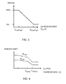
- Figure 3 is a diagram of various clutch energies and how they are rated.
- the system comprises also a rating unit 5 adapted to rating the clutch wear on the basis of said result and generating a rating signal Sg which indicates said rating. The driver's behaviour is then scored on the basis of the calculated energy E slip lost through the clutch. A very large amount of clutch energy generated results in a low rating, and a small amount of clutch energy generated a high rating.
- the rating scale in Figure 3 runs from 0 to 100% but other scales, e.g. 0 to 10, would be equally possible.
- the system further comprises an indicating unit 6 adapted to feeding the rating back to the driver.
- the indicating unit may for example be a display in the vehicle's instrument panel which shows the vehicle's ratings in the form of numerals or symbols.
- the system comprises a time unit 7 adapted to monitoring the driver's use of the clutch control by detecting a slip period t slip which is the time the driver takes to release the clutch from a disconnected state to a connected state.
- a slip period t slip which is the time the driver takes to release the clutch from a disconnected state to a connected state.
- pedal sensors may monitor the clutch pedal and detect its position in terms of closed and open.
- the comparison unit 4 is adapted to determining said limits for the clutch energy E slip with respect to the temperature of the clutch. This makes it possible to determine the clutch temperature limits within which the vehicle should be set in motion. Temperature sensors in the clutch may be avoided by using an estimate of the clutch temperature.
- Figure 4 illustrates an example of energy limits E HIGH and E LOW determined as a function of the clutch temperature.
- the temperature in the clutch may be determined as follows.
- the material of the clutch may be divided into two kinds, viz. 1: clutch disc and 2: surrounding material (flywheel, clutch housing, air, etc.).
- the clutch disc is assumed to absorb heat when slipping and then transfer it to surrounding material which itself gives off heat to the surroundings. This is illustrated in Figure 6 , in which the arrows indicate the direction of heat movement.
- k is a constant for the material, A the area of the disc and d the thickness of the disc.
- the thermal capacity i.e.
- m the weight of the material
- c the thermal capacity.
- k absorb is estimated by measuring the temperature increase when a given amount of energy is quickly supplied.
- the k conduct is estimated by measuring the cooling time for a component when k absorb is already known.
- the ambient temperature T ambient may for example be assumed to be a weighted average of engine temperature and air temperature. Cooling at higher speeds may also be taken into account.
- the system comprises a first monitoring unit 8 adapted to determining the temperature of the clutch and to generating a signal to the driver that the temperature in the clutch is high, if the vehicle has come to a halt and the temperature exceeds a predetermined threshold value.
- T critical a very low gear is required to meet the wear requirements.
- the system comprises a second monitoring unit 9 adapted to detecting settings of the gearbox, and if it is in a high gear, the vehicle is stationary and the driver releases the brake pedal, the monitoring unit 9 is adapted to generating a signal to the driver that a high gear is set.
- an expected scenario is that acceleration will follow. The driver may thus be made aware that the vehicle is about to move off in too high a gear, enabling him/her to downshift in time.
- the monitoring unit 9 is preferably adapted to monitoring whether the vehicle is stationary and to receiving signals from a sensor which monitors the position of the brake pedal.
- the monitoring unit 9 is adapted to detecting whether the gearbox is set in the high-speed or the low-speed section. If it finds that the gearbox is set in the high-speed section, the vehicle is stationary and the driver releases the brake pedal, the monitoring unit 9 according to this embodiment is adapted to generating a signal to the driver that a gear in the high-speed section is set. The risk that the driver might move off with the gear set in the high-speed section can thus be reduced.
- the system comprises according to an embodiment an identifying unit adapted to identifying what the driver has done wrong, by analysing the situation which has arisen.
- M takeoff F takeoff ⁇ r wheel i rear_axle ⁇ i gear ⁇ ⁇ gear ⁇ ⁇ axle , in which r wheel is wheel radius, i rear _ axle the ratio of the rear axle, i gear the ratio of the initial gear, ⁇ gear and ⁇ axle the respective efficiencies of the initial gear and the axle.
- the identifying unit 10 is thus adapted to calculating the engine torque M takeoff which was required to accelerate the vehicle for an initial distance d takeoff .M takeoff is then compared with at least one predetermined value M max of the engine torque, and if M takeoff exceeds a M max an indicating signal is generated to the driver that the vehicle's initial gear was too high when moving off. A limit is thus set for the engine torque which is acceptable when setting the vehicle in motion. The signal may include tips to the driver for improving his/her behaviour. If M takeoff was too high, the driver is reminded that this was so. He/she thus gradually learns which initial gears are appropriate to different road gradients and different loads. This reminder is not given if the lowest gear is already being used.
- the identifying unit 10 is adapted to comparing the time t slip with at least one predetermined time value t max , and if t slip exceeds t max an indicating signal is generated to the driver that the time taken to release the clutch pedal was too long. He/she may thus be made aware that the time taken to release the clutch was too long.
- the signal may include tips to the driver for improving his/her driving behaviour by being reminded to release the clutch more quickly moving off.
- the identifying unit 10 is adapted to comparing the engine's speed n eng when the vehicle is being set in motion with at least one predetermined engine speed value n max and, if n eng exceeds n max , to generating an indicating signal to the driver that the engine speed was too high when moving off.
- the signal may include tips for improving his/her driving behaviour by being reminded to keep the engine speed down when releasing the clutch.
- the invention comprises also a method for assessing a driver's wear of a friction clutch.
- the method comprises a first step S 1 of determining a value of the clutch energy E slip during a slip period, depending on the power output P eng and the clutch slip s.
- E slip is determined by using equations (1) to (7) set out above.
- a second step S2 generates an energy signal which indicates said value of E slip .
- a third step S3 then compares the calculated value of the clutch energy E slip with limits for the clutch energy. This is illustrated in Figure 3 .
- a fourth step S4 generates a comparison signal which indicates the result of said comparison.
- a fifth step S5 rates the clutch wear on the basis of said result.
- a sixth step S6 generates a rating signal which indicates said rating.
- a seventh step S7 feeds the rating back to the driver. He/she is thus made aware of how well he/she has used the clutch as regards wear.
- the method comprises determining said limits for the clutch energy E slip with respect to the temperature of the clutch.
- An example of relationships between the clutch temperature and limits for the clutch energy appears in Figure 4 . If the clutch temperature is high, the limits for the clutch energy will be low.
- the method comprises monitoring the driver's use of the clutch control by detecting a slip period t slip as an amount of time which the driver takes to release the clutch from a disconnected state to a connected state. Only the energy used during the slip period is thus taken into account in the assessment.
- the method comprises, according to an embodiment, detecting settings of the gearbox 2. If the gearbox is set in a high gear, the vehicle is stationary and the driver releases the brake pedal, a signal is then generated to him/her that a high gear is set. The driver may thus be reminded to switch to low gear if he/she forgets to do so before setting the vehicle in motion. He/she then avoids moving off in too high a gear which would result in greater clutch wear. If the gearbox is divided into high-speed and low-speed sections, this setting may also be detected and the driver be warned if too high a gear is set.
- the method comprises determining the temperature of the clutch 1 and generating a signal to the driver that the temperature in the clutch 1 is high, if the vehicle has come to a halt and the temperature exceeds a predetermined threshold value.
- the driver may thus be made aware that the clutch temperature is too high and that a lower gear should be set for the next move-off.
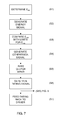
- the method comprises, according to an embodiment, doing an evaluation according to the method steps of the flowchart in Figure 8 .
- This identification is based on a rating signal generated at step S6 in Figure 7 .
- the rating is evaluated at step S80, and if it is poor, the identification of what has caused the poor rating begins.
- a poor rating may for example be within the range 1-5 on a scale of 1-10.
- Step S81 identifies whether too high an initial gear has been used. Identification of too high an initial gear is done, according to an embodiment, by calculating the engine torque M takeoff which was required to accelerate the vehicle for an initial distance d takeoff and by comparing M takeoff with at least one predetermined value M max of the engine torque.
- Step S82 identifies whether M takeoff exceeds M max , in which case a step S800 generates a signal to the driver that the vehicle's initial gear was too high when moving off.
- M takeoff may be determined by means of equations (14) to (16) above. The driver may thus be made aware that he/she used too high an initial gear.
- Step S83 identifies whether the poor rating was due to too high an engine speed when moving off. This is done according to an embodiment by comparing the engine's speed n eng during move-off with at least one predetermined engine speed value n max. Step S84 identifies whether n eng exceeds n max , in which case a step S800 generates an indicating signal to the driver that the engine speed was too high when moving off. The driver may thus be made aware that he/she used too high an engine speed when setting the vehicle in motion.
- Step S85 identifies whether the poor rating was due to the driver having taken too much time to release the clutch when setting the vehicle in motion. This is done according to an embodiment by comparing the time t slip with at least one predetermined time value t max. The next step S86 identifies whether t slip exceeds t max , in which case a step S800 generates a signal to the driver that the time taken to release the clutch pedal was too long. The driver may thus be made aware of how good he/she is at releasing the clutch as regards wear, and may be encouraged to reduce the time taken.
- the above embodiments may be effected in different sequences and need not be confined to the sequence in Figure 8 . It is also possible to indicate to the driver only one reason for poor ratings, thus stopping at the positive judgement arising from the first identification of fault. If there are two or more reasons for poor ratings, they may of course be communicated to the driver all together.
- the indicating signal to the driver may also contain tips on how to improve his/her driving behaviour. Tips from the various embodiments may for example be presented in order of priority or alternatively only the tip regarded as most important may be presented to the driver.
- the invention comprises also a computer programme product comprising programme instructions for enabling a computer system in a vehicle to perform the steps according to the above method when those instructions are run on said computer system.
- the invention comprises also a computer programme product in which the programme instructions are stored on a medium which can be read by a computer system.
Landscapes
- Engineering & Computer Science (AREA)
- Mechanical Engineering (AREA)
- General Engineering & Computer Science (AREA)
- Automation & Control Theory (AREA)
- Transportation (AREA)
- Physics & Mathematics (AREA)
- Human Computer Interaction (AREA)
- Mathematical Physics (AREA)
- Fluid Mechanics (AREA)
- Mechanical Operated Clutches (AREA)
- Hydraulic Clutches, Magnetic Clutches, Fluid Clutches, And Fluid Joints (AREA)
Applications Claiming Priority (1)
| Application Number | Priority Date | Filing Date | Title |
|---|---|---|---|
| SE1051274A SE535427C2 (sv) | 2010-12-02 | 2010-12-02 | Metod och system för bedömning av kopplingsslitage |
Publications (3)
| Publication Number | Publication Date |
|---|---|
| EP2461064A2 true EP2461064A2 (de) | 2012-06-06 |
| EP2461064A3 EP2461064A3 (de) | 2012-11-14 |
| EP2461064B1 EP2461064B1 (de) | 2014-07-30 |
Family
ID=45065754
Family Applications (1)
| Application Number | Title | Priority Date | Filing Date |
|---|---|---|---|
| EP11190348.0A Active EP2461064B1 (de) | 2010-12-02 | 2011-11-23 | Verfahren und System zur Einschätzung der Kupplungsabnutzung |
Country Status (3)
| Country | Link |
|---|---|
| EP (1) | EP2461064B1 (de) |
| BR (1) | BRPI1105056B1 (de) |
| SE (1) | SE535427C2 (de) |
Cited By (3)
| Publication number | Priority date | Publication date | Assignee | Title |
|---|---|---|---|---|
| WO2018233757A1 (de) * | 2017-06-21 | 2018-12-27 | Schaeffler Technologies AG & Co. KG | Verfahren zur korrekten bestimmung einer in einer kupplung entstehenden reibenergie während einer anfahrt eines fahrzeuges mit einem handschaltgetriebe |
| CN110406524A (zh) * | 2018-04-26 | 2019-11-05 | 康明斯公司 | 离合器滥用指示器 |
| CN113859245A (zh) * | 2021-09-13 | 2021-12-31 | 东风汽车集团股份有限公司 | 一种确定离合器摩擦损耗的方法、装置、介质及设备 |
Citations (4)
| Publication number | Priority date | Publication date | Assignee | Title |
|---|---|---|---|---|
| WO2001072546A1 (en) | 2000-03-27 | 2001-10-04 | Scania Cv Ab (Publ) | Method and apparatus for indication of clutch slip |
| EP1482196A1 (de) | 2003-05-30 | 2004-12-01 | MAN Nutzfahrzeuge Aktiengesellschaft | Verfahren zur Begründung des Verschleisses einer Reibungskupplung zwischen einem Verbrennungsmotor und einem Schaltgetriebe eines Nutzfahrzeuges |
| DE102008007559A1 (de) | 2008-02-05 | 2009-01-29 | Daimler Ag | Überwachungseinrichtung |
| WO2010020520A1 (de) | 2008-08-22 | 2010-02-25 | Robert Bosch Gmbh | Verfahren zum erfassen eines verschleisses einer motortrennkupplung |
Family Cites Families (12)
| Publication number | Priority date | Publication date | Assignee | Title |
|---|---|---|---|---|
| DE19602006A1 (de) * | 1995-01-28 | 1996-08-01 | Luk Getriebe Systeme Gmbh | Vorrichtung und ein Verfahren zur Ansteuerung eines Drehmomentübertragungssystems |
| DE19639296C1 (de) * | 1996-09-25 | 1998-04-02 | Daimler Benz Ag | Zwischen Motor und Antriebstrang eines Kraftfahrzeuges angeordnete Kupplung |
| DE10316454B4 (de) * | 2002-04-10 | 2021-05-20 | Schaeffler Technologies AG & Co. KG | Vorrichtung und Verfahren zum Überwachen einer Kupplung |
| DE102004023581A1 (de) * | 2004-05-13 | 2005-12-08 | Adam Opel Ag | Verfahren zur Steuerung einer Kupplung und/oder eines Kraftfahrzeuggetriebes |
| US8370037B2 (en) * | 2004-06-30 | 2013-02-05 | Schaeffler Technologies AG & Co. KG | Method for the protection of an automatically actuated clutch of a vehicle from overload |
| DE102005061080A1 (de) * | 2005-01-20 | 2006-07-27 | Luk Lamellen Und Kupplungsbau Beteiligungs Kg | Verfahren und Vorrichtung zum Erkennen einer Schädigung einer Kupplung mit wenigstens zwei durch Reibeingriff Drehmoment übertragenden Bauteilen |
| DE102005026615A1 (de) * | 2005-06-09 | 2006-12-14 | Zf Friedrichshafen Ag | Verfahren und Vorrichtung zur Steuerung einer automatisierten Reibkupplung zwischen einem Motor und einem Getriebe |
| DE102006037389A1 (de) * | 2006-08-10 | 2008-02-14 | Daimler Ag | Verfahren zur Abschätzung einer an einer Anfahrkupplung eines Kraftfahrzeugs dissipierten Energiemenge |
| JP5232441B2 (ja) * | 2007-10-30 | 2013-07-10 | 三菱重工業株式会社 | クラッチ装置の警報装置 |
| US8062178B2 (en) * | 2008-11-05 | 2011-11-22 | Ford Global Technologies, Llc | Temperature control of dual input clutch transmission |
| SE533138C2 (sv) * | 2008-11-21 | 2010-07-06 | Scania Cv Abp | Växelåterkopplingssystem |
| SE0950384A1 (sv) * | 2009-05-28 | 2010-11-29 | Scania Cv Ab | Metod och system för visning av information relaterat till hur ett fordon framförs |
-
2010
- 2010-12-02 SE SE1051274A patent/SE535427C2/sv unknown
-
2011
- 2011-11-23 EP EP11190348.0A patent/EP2461064B1/de active Active
- 2011-11-28 BR BRPI1105056-0A patent/BRPI1105056B1/pt active IP Right Grant
Patent Citations (4)
| Publication number | Priority date | Publication date | Assignee | Title |
|---|---|---|---|---|
| WO2001072546A1 (en) | 2000-03-27 | 2001-10-04 | Scania Cv Ab (Publ) | Method and apparatus for indication of clutch slip |
| EP1482196A1 (de) | 2003-05-30 | 2004-12-01 | MAN Nutzfahrzeuge Aktiengesellschaft | Verfahren zur Begründung des Verschleisses einer Reibungskupplung zwischen einem Verbrennungsmotor und einem Schaltgetriebe eines Nutzfahrzeuges |
| DE102008007559A1 (de) | 2008-02-05 | 2009-01-29 | Daimler Ag | Überwachungseinrichtung |
| WO2010020520A1 (de) | 2008-08-22 | 2010-02-25 | Robert Bosch Gmbh | Verfahren zum erfassen eines verschleisses einer motortrennkupplung |
Cited By (5)
| Publication number | Priority date | Publication date | Assignee | Title |
|---|---|---|---|---|
| WO2018233757A1 (de) * | 2017-06-21 | 2018-12-27 | Schaeffler Technologies AG & Co. KG | Verfahren zur korrekten bestimmung einer in einer kupplung entstehenden reibenergie während einer anfahrt eines fahrzeuges mit einem handschaltgetriebe |
| CN110651134A (zh) * | 2017-06-21 | 2020-01-03 | 舍弗勒技术股份两合公司 | 用于经校正地确定在具有手动变速器的车辆起动期间在离合器中生成的摩擦能量的方法 |
| CN110651134B (zh) * | 2017-06-21 | 2021-04-02 | 舍弗勒技术股份两合公司 | 用于经校正地确定在具有手动变速器的车辆起动期间在离合器中生成的摩擦能量的方法 |
| CN110406524A (zh) * | 2018-04-26 | 2019-11-05 | 康明斯公司 | 离合器滥用指示器 |
| CN113859245A (zh) * | 2021-09-13 | 2021-12-31 | 东风汽车集团股份有限公司 | 一种确定离合器摩擦损耗的方法、装置、介质及设备 |
Also Published As
| Publication number | Publication date |
|---|---|
| BRPI1105056B1 (pt) | 2021-05-11 |
| EP2461064A3 (de) | 2012-11-14 |
| BRPI1105056A2 (pt) | 2013-03-12 |
| EP2461064B1 (de) | 2014-07-30 |
| SE1051274A1 (sv) | 2012-06-03 |
| SE535427C2 (sv) | 2012-08-07 |
Similar Documents
| Publication | Publication Date | Title |
|---|---|---|
| US5723779A (en) | System for determining residual life of friction clutch | |
| US8651256B2 (en) | Method and arrangement for determining the wear condition of a shifting clutch | |
| JP5443610B2 (ja) | 自動車内自動駐車ブレーキの作動方法 | |
| EP3042095B1 (de) | System und verfahren zur voraussage der restlebensdauer einer kupplung durch schätzung des reibungskoeffizienten | |
| CN103802824A (zh) | 学习混合动力车辆的发动机离合器的操作的方法和系统 | |
| US20060154781A1 (en) | Process for operating an automatically actuated friction clutch and/or a transmission | |
| SE1251304A1 (sv) | Bränsleförbrukningsanalys i ett fordon | |
| EP2359032B1 (de) | Getriebefeedbacksystem | |
| CN103459876A (zh) | 用于确定湿式离合器的温度的方法 | |
| JP2004515402A (ja) | 車両の運転モード中に発生するアクアプレーニングの危険性を検出するための装置 | |
| JP2010065637A (ja) | 産業車両の潤滑油劣化診断方法及び装置 | |
| JP2007271282A (ja) | 流体継手を備えた車両の車両重量検出装置 | |
| JPH08303485A (ja) | 多板摩擦クラッチの残存寿命判定装置 | |
| EP2461064B1 (de) | Verfahren und System zur Einschätzung der Kupplungsabnutzung | |
| US7603220B2 (en) | Method and system for detecting damage done to a clutch having at least two components that transfer torque by frictional engagement | |
| CN105782270A (zh) | 干式离合器摩擦转矩实时监测和控制方法 | |
| JP2010065795A (ja) | 産業車両のクラッチ故障診断方法及び装置 | |
| US10245949B2 (en) | Method for operating a motor vehicle including an all-wheel drive that can be enabled and disabled by determining an angular acceleration of components, which are uncoupled when the all-wheel drive is disabled | |
| SE533139C2 (sv) | System för fastställande av förmåga att förutse inbromsning | |
| US8838352B2 (en) | Method and device for selecting a starting gear in a vehicle | |
| EP2767817B1 (de) | Verfahren, Vorrichtung, Rechnerprogram und computerlesbares Aufzeichnungsmedium zur Überwachung des Verschleißes der Kupplung eines manuellen oder eines automatischen manuellen Getriebes, insbesondere für Schwerfahrzeuge | |
| RU2561400C2 (ru) | Способ и система оценки поведения торможения водителя | |
| CN108799360B (zh) | 用于确定一种离合器的状况的方法 | |
| US20190077390A1 (en) | Energy based park brake end of life detection system and method | |
| US20190084574A1 (en) | Digital Clutch Gauge |
Legal Events
| Date | Code | Title | Description |
|---|---|---|---|
| PUAI | Public reference made under article 153(3) epc to a published international application that has entered the european phase |
Free format text: ORIGINAL CODE: 0009012 |
|
| AK | Designated contracting states |
Kind code of ref document: A2 Designated state(s): AL AT BE BG CH CY CZ DE DK EE ES FI FR GB GR HR HU IE IS IT LI LT LU LV MC MK MT NL NO PL PT RO RS SE SI SK SM TR |
|
| AX | Request for extension of the european patent |
Extension state: BA ME |
|
| PUAL | Search report despatched |
Free format text: ORIGINAL CODE: 0009013 |
|
| AK | Designated contracting states |
Kind code of ref document: A3 Designated state(s): AL AT BE BG CH CY CZ DE DK EE ES FI FR GB GR HR HU IE IS IT LI LT LU LV MC MK MT NL NO PL PT RO RS SE SI SK SM TR |
|
| AX | Request for extension of the european patent |
Extension state: BA ME |
|
| RIC1 | Information provided on ipc code assigned before grant |
Ipc: F16D 48/06 20060101AFI20121009BHEP |
|
| 17P | Request for examination filed |
Effective date: 20130514 |
|
| 17Q | First examination report despatched |
Effective date: 20130614 |
|
| GRAP | Despatch of communication of intention to grant a patent |
Free format text: ORIGINAL CODE: EPIDOSNIGR1 |
|
| INTG | Intention to grant announced |
Effective date: 20140416 |
|
| GRAS | Grant fee paid |
Free format text: ORIGINAL CODE: EPIDOSNIGR3 |
|
| GRAA | (expected) grant |
Free format text: ORIGINAL CODE: 0009210 |
|
| AK | Designated contracting states |
Kind code of ref document: B1 Designated state(s): AL AT BE BG CH CY CZ DE DK EE ES FI FR GB GR HR HU IE IS IT LI LT LU LV MC MK MT NL NO PL PT RO RS SE SI SK SM TR |
|
| REG | Reference to a national code |
Ref country code: GB Ref legal event code: FG4D |
|
| REG | Reference to a national code |
Ref country code: CH Ref legal event code: EP |
|
| REG | Reference to a national code |
Ref country code: AT Ref legal event code: REF Ref document number: 680143 Country of ref document: AT Kind code of ref document: T Effective date: 20140815 |
|
| REG | Reference to a national code |
Ref country code: IE Ref legal event code: FG4D |
|
| REG | Reference to a national code |
Ref country code: DE Ref legal event code: R096 Ref document number: 602011008692 Country of ref document: DE Effective date: 20140911 |
|
| REG | Reference to a national code |
Ref country code: AT Ref legal event code: MK05 Ref document number: 680143 Country of ref document: AT Kind code of ref document: T Effective date: 20140730 |
|
| REG | Reference to a national code |
Ref country code: NL Ref legal event code: VDEP Effective date: 20140730 |
|
| REG | Reference to a national code |
Ref country code: LT Ref legal event code: MG4D |
|
| PG25 | Lapsed in a contracting state [announced via postgrant information from national office to epo] |
Ref country code: NO Free format text: LAPSE BECAUSE OF FAILURE TO SUBMIT A TRANSLATION OF THE DESCRIPTION OR TO PAY THE FEE WITHIN THE PRESCRIBED TIME-LIMIT Effective date: 20141030 Ref country code: LT Free format text: LAPSE BECAUSE OF FAILURE TO SUBMIT A TRANSLATION OF THE DESCRIPTION OR TO PAY THE FEE WITHIN THE PRESCRIBED TIME-LIMIT Effective date: 20140730 Ref country code: ES Free format text: LAPSE BECAUSE OF FAILURE TO SUBMIT A TRANSLATION OF THE DESCRIPTION OR TO PAY THE FEE WITHIN THE PRESCRIBED TIME-LIMIT Effective date: 20140730 Ref country code: BG Free format text: LAPSE BECAUSE OF FAILURE TO SUBMIT A TRANSLATION OF THE DESCRIPTION OR TO PAY THE FEE WITHIN THE PRESCRIBED TIME-LIMIT Effective date: 20141030 Ref country code: SE Free format text: LAPSE BECAUSE OF FAILURE TO SUBMIT A TRANSLATION OF THE DESCRIPTION OR TO PAY THE FEE WITHIN THE PRESCRIBED TIME-LIMIT Effective date: 20140730 Ref country code: FI Free format text: LAPSE BECAUSE OF FAILURE TO SUBMIT A TRANSLATION OF THE DESCRIPTION OR TO PAY THE FEE WITHIN THE PRESCRIBED TIME-LIMIT Effective date: 20140730 Ref country code: PT Free format text: LAPSE BECAUSE OF FAILURE TO SUBMIT A TRANSLATION OF THE DESCRIPTION OR TO PAY THE FEE WITHIN THE PRESCRIBED TIME-LIMIT Effective date: 20141202 Ref country code: GR Free format text: LAPSE BECAUSE OF FAILURE TO SUBMIT A TRANSLATION OF THE DESCRIPTION OR TO PAY THE FEE WITHIN THE PRESCRIBED TIME-LIMIT Effective date: 20141031 |
|
| PG25 | Lapsed in a contracting state [announced via postgrant information from national office to epo] |
Ref country code: CY Free format text: LAPSE BECAUSE OF FAILURE TO SUBMIT A TRANSLATION OF THE DESCRIPTION OR TO PAY THE FEE WITHIN THE PRESCRIBED TIME-LIMIT Effective date: 20140730 Ref country code: LV Free format text: LAPSE BECAUSE OF FAILURE TO SUBMIT A TRANSLATION OF THE DESCRIPTION OR TO PAY THE FEE WITHIN THE PRESCRIBED TIME-LIMIT Effective date: 20140730 Ref country code: RS Free format text: LAPSE BECAUSE OF FAILURE TO SUBMIT A TRANSLATION OF THE DESCRIPTION OR TO PAY THE FEE WITHIN THE PRESCRIBED TIME-LIMIT Effective date: 20140730 Ref country code: IS Free format text: LAPSE BECAUSE OF FAILURE TO SUBMIT A TRANSLATION OF THE DESCRIPTION OR TO PAY THE FEE WITHIN THE PRESCRIBED TIME-LIMIT Effective date: 20141130 Ref country code: AT Free format text: LAPSE BECAUSE OF FAILURE TO SUBMIT A TRANSLATION OF THE DESCRIPTION OR TO PAY THE FEE WITHIN THE PRESCRIBED TIME-LIMIT Effective date: 20140730 Ref country code: PL Free format text: LAPSE BECAUSE OF FAILURE TO SUBMIT A TRANSLATION OF THE DESCRIPTION OR TO PAY THE FEE WITHIN THE PRESCRIBED TIME-LIMIT Effective date: 20140730 Ref country code: NL Free format text: LAPSE BECAUSE OF FAILURE TO SUBMIT A TRANSLATION OF THE DESCRIPTION OR TO PAY THE FEE WITHIN THE PRESCRIBED TIME-LIMIT Effective date: 20140730 Ref country code: HR Free format text: LAPSE BECAUSE OF FAILURE TO SUBMIT A TRANSLATION OF THE DESCRIPTION OR TO PAY THE FEE WITHIN THE PRESCRIBED TIME-LIMIT Effective date: 20140730 |
|
| PG25 | Lapsed in a contracting state [announced via postgrant information from national office to epo] |
Ref country code: SK Free format text: LAPSE BECAUSE OF FAILURE TO SUBMIT A TRANSLATION OF THE DESCRIPTION OR TO PAY THE FEE WITHIN THE PRESCRIBED TIME-LIMIT Effective date: 20140730 Ref country code: CZ Free format text: LAPSE BECAUSE OF FAILURE TO SUBMIT A TRANSLATION OF THE DESCRIPTION OR TO PAY THE FEE WITHIN THE PRESCRIBED TIME-LIMIT Effective date: 20140730 Ref country code: RO Free format text: LAPSE BECAUSE OF FAILURE TO SUBMIT A TRANSLATION OF THE DESCRIPTION OR TO PAY THE FEE WITHIN THE PRESCRIBED TIME-LIMIT Effective date: 20140730 Ref country code: DK Free format text: LAPSE BECAUSE OF FAILURE TO SUBMIT A TRANSLATION OF THE DESCRIPTION OR TO PAY THE FEE WITHIN THE PRESCRIBED TIME-LIMIT Effective date: 20140730 Ref country code: EE Free format text: LAPSE BECAUSE OF FAILURE TO SUBMIT A TRANSLATION OF THE DESCRIPTION OR TO PAY THE FEE WITHIN THE PRESCRIBED TIME-LIMIT Effective date: 20140730 |
|
| REG | Reference to a national code |
Ref country code: DE Ref legal event code: R097 Ref document number: 602011008692 Country of ref document: DE |
|
| PLBE | No opposition filed within time limit |
Free format text: ORIGINAL CODE: 0009261 |
|
| STAA | Information on the status of an ep patent application or granted ep patent |
Free format text: STATUS: NO OPPOSITION FILED WITHIN TIME LIMIT |
|
| PG25 | Lapsed in a contracting state [announced via postgrant information from national office to epo] |
Ref country code: MC Free format text: LAPSE BECAUSE OF FAILURE TO SUBMIT A TRANSLATION OF THE DESCRIPTION OR TO PAY THE FEE WITHIN THE PRESCRIBED TIME-LIMIT Effective date: 20140730 Ref country code: BE Free format text: LAPSE BECAUSE OF NON-PAYMENT OF DUE FEES Effective date: 20141130 Ref country code: LU Free format text: LAPSE BECAUSE OF FAILURE TO SUBMIT A TRANSLATION OF THE DESCRIPTION OR TO PAY THE FEE WITHIN THE PRESCRIBED TIME-LIMIT Effective date: 20141123 |
|
| REG | Reference to a national code |
Ref country code: CH Ref legal event code: PL |
|
| 26N | No opposition filed |
Effective date: 20150504 |
|
| PG25 | Lapsed in a contracting state [announced via postgrant information from national office to epo] |
Ref country code: CH Free format text: LAPSE BECAUSE OF NON-PAYMENT OF DUE FEES Effective date: 20141130 Ref country code: LI Free format text: LAPSE BECAUSE OF NON-PAYMENT OF DUE FEES Effective date: 20141130 |
|
| REG | Reference to a national code |
Ref country code: IE Ref legal event code: MM4A |
|
| REG | Reference to a national code |
Ref country code: FR Ref legal event code: PLFP Year of fee payment: 5 |
|
| PG25 | Lapsed in a contracting state [announced via postgrant information from national office to epo] |
Ref country code: IE Free format text: LAPSE BECAUSE OF NON-PAYMENT OF DUE FEES Effective date: 20141123 |
|
| PG25 | Lapsed in a contracting state [announced via postgrant information from national office to epo] |
Ref country code: SI Free format text: LAPSE BECAUSE OF FAILURE TO SUBMIT A TRANSLATION OF THE DESCRIPTION OR TO PAY THE FEE WITHIN THE PRESCRIBED TIME-LIMIT Effective date: 20140730 |
|
| PG25 | Lapsed in a contracting state [announced via postgrant information from national office to epo] |
Ref country code: SM Free format text: LAPSE BECAUSE OF FAILURE TO SUBMIT A TRANSLATION OF THE DESCRIPTION OR TO PAY THE FEE WITHIN THE PRESCRIBED TIME-LIMIT Effective date: 20140730 |
|
| PG25 | Lapsed in a contracting state [announced via postgrant information from national office to epo] |
Ref country code: HU Free format text: LAPSE BECAUSE OF FAILURE TO SUBMIT A TRANSLATION OF THE DESCRIPTION OR TO PAY THE FEE WITHIN THE PRESCRIBED TIME-LIMIT; INVALID AB INITIO Effective date: 20111123 Ref country code: BE Free format text: LAPSE BECAUSE OF FAILURE TO SUBMIT A TRANSLATION OF THE DESCRIPTION OR TO PAY THE FEE WITHIN THE PRESCRIBED TIME-LIMIT Effective date: 20140730 Ref country code: TR Free format text: LAPSE BECAUSE OF FAILURE TO SUBMIT A TRANSLATION OF THE DESCRIPTION OR TO PAY THE FEE WITHIN THE PRESCRIBED TIME-LIMIT Effective date: 20140730 Ref country code: MT Free format text: LAPSE BECAUSE OF FAILURE TO SUBMIT A TRANSLATION OF THE DESCRIPTION OR TO PAY THE FEE WITHIN THE PRESCRIBED TIME-LIMIT Effective date: 20140730 |
|
| REG | Reference to a national code |
Ref country code: FR Ref legal event code: PLFP Year of fee payment: 6 |
|
| REG | Reference to a national code |
Ref country code: FR Ref legal event code: PLFP Year of fee payment: 7 |
|
| PG25 | Lapsed in a contracting state [announced via postgrant information from national office to epo] |
Ref country code: MK Free format text: LAPSE BECAUSE OF FAILURE TO SUBMIT A TRANSLATION OF THE DESCRIPTION OR TO PAY THE FEE WITHIN THE PRESCRIBED TIME-LIMIT Effective date: 20140730 |
|
| REG | Reference to a national code |
Ref country code: FR Ref legal event code: PLFP Year of fee payment: 8 |
|
| PG25 | Lapsed in a contracting state [announced via postgrant information from national office to epo] |
Ref country code: AL Free format text: LAPSE BECAUSE OF FAILURE TO SUBMIT A TRANSLATION OF THE DESCRIPTION OR TO PAY THE FEE WITHIN THE PRESCRIBED TIME-LIMIT Effective date: 20140730 |
|
| P01 | Opt-out of the competence of the unified patent court (upc) registered |
Effective date: 20230518 |
|
| PGFP | Annual fee paid to national office [announced via postgrant information from national office to epo] |
Ref country code: FR Payment date: 20230929 Year of fee payment: 13 |
|
| PGFP | Annual fee paid to national office [announced via postgrant information from national office to epo] |
Ref country code: GB Payment date: 20231006 Year of fee payment: 13 |
|
| PGFP | Annual fee paid to national office [announced via postgrant information from national office to epo] |
Ref country code: IT Payment date: 20231010 Year of fee payment: 13 Ref country code: DE Payment date: 20230929 Year of fee payment: 13 |