EP2460639B1 - Vorrichtung zur Blasformung von Behältnissen - Google Patents
Vorrichtung zur Blasformung von Behältnissen Download PDFInfo
- Publication number
- EP2460639B1 EP2460639B1 EP11191606.0A EP11191606A EP2460639B1 EP 2460639 B1 EP2460639 B1 EP 2460639B1 EP 11191606 A EP11191606 A EP 11191606A EP 2460639 B1 EP2460639 B1 EP 2460639B1
- Authority
- EP
- European Patent Office
- Prior art keywords
- control piston
- control
- piston
- cylinder
- plastic
- Prior art date
- Legal status (The legal status is an assumption and is not a legal conclusion. Google has not performed a legal analysis and makes no representation as to the accuracy of the status listed.)
- Active
Links
- 238000000071 blow moulding Methods 0.000 title claims description 13
- 239000004033 plastic Substances 0.000 claims description 51
- 238000007789 sealing Methods 0.000 claims description 38
- 229910052751 metal Inorganic materials 0.000 claims description 17
- 239000002184 metal Substances 0.000 claims description 17
- 239000000919 ceramic Substances 0.000 claims description 14
- 239000012815 thermoplastic material Substances 0.000 claims description 3
- 238000006073 displacement reaction Methods 0.000 claims description 2
- 238000010276 construction Methods 0.000 claims 1
- 239000011796 hollow space material Substances 0.000 claims 1
- 238000007664 blowing Methods 0.000 description 29
- 230000003584 silencer Effects 0.000 description 5
- 230000002093 peripheral effect Effects 0.000 description 4
- 229920001875 Ebonite Polymers 0.000 description 2
- FYYHWMGAXLPEAU-UHFFFAOYSA-N Magnesium Chemical compound [Mg] FYYHWMGAXLPEAU-UHFFFAOYSA-N 0.000 description 2
- 238000011156 evaluation Methods 0.000 description 2
- 229910052749 magnesium Inorganic materials 0.000 description 2
- 239000011777 magnesium Substances 0.000 description 2
- 238000000034 method Methods 0.000 description 2
- 229910052782 aluminium Inorganic materials 0.000 description 1
- XAGFODPZIPBFFR-UHFFFAOYSA-N aluminium Chemical compound [Al] XAGFODPZIPBFFR-UHFFFAOYSA-N 0.000 description 1
- 230000000903 blocking effect Effects 0.000 description 1
- 230000001419 dependent effect Effects 0.000 description 1
- 239000000463 material Substances 0.000 description 1
- 230000007246 mechanism Effects 0.000 description 1
- 150000002739 metals Chemical class 0.000 description 1
- 238000013022 venting Methods 0.000 description 1
- 239000013585 weight reducing agent Substances 0.000 description 1
Images


Classifications
-
- B—PERFORMING OPERATIONS; TRANSPORTING
- B29—WORKING OF PLASTICS; WORKING OF SUBSTANCES IN A PLASTIC STATE IN GENERAL
- B29C—SHAPING OR JOINING OF PLASTICS; SHAPING OF MATERIAL IN A PLASTIC STATE, NOT OTHERWISE PROVIDED FOR; AFTER-TREATMENT OF THE SHAPED PRODUCTS, e.g. REPAIRING
- B29C49/00—Blow-moulding, i.e. blowing a preform or parison to a desired shape within a mould; Apparatus therefor
- B29C49/42—Component parts, details or accessories; Auxiliary operations
- B29C49/78—Measuring, controlling or regulating
-
- B—PERFORMING OPERATIONS; TRANSPORTING
- B29—WORKING OF PLASTICS; WORKING OF SUBSTANCES IN A PLASTIC STATE IN GENERAL
- B29C—SHAPING OR JOINING OF PLASTICS; SHAPING OF MATERIAL IN A PLASTIC STATE, NOT OTHERWISE PROVIDED FOR; AFTER-TREATMENT OF THE SHAPED PRODUCTS, e.g. REPAIRING
- B29C49/00—Blow-moulding, i.e. blowing a preform or parison to a desired shape within a mould; Apparatus therefor
- B29C49/42—Component parts, details or accessories; Auxiliary operations
- B29C49/4289—Valve constructions or configurations, e.g. arranged to reduce blowing fluid consumption
-
- B—PERFORMING OPERATIONS; TRANSPORTING
- B29—WORKING OF PLASTICS; WORKING OF SUBSTANCES IN A PLASTIC STATE IN GENERAL
- B29C—SHAPING OR JOINING OF PLASTICS; SHAPING OF MATERIAL IN A PLASTIC STATE, NOT OTHERWISE PROVIDED FOR; AFTER-TREATMENT OF THE SHAPED PRODUCTS, e.g. REPAIRING
- B29C49/00—Blow-moulding, i.e. blowing a preform or parison to a desired shape within a mould; Apparatus therefor
- B29C49/42—Component parts, details or accessories; Auxiliary operations
- B29C49/58—Blowing means
-
- B—PERFORMING OPERATIONS; TRANSPORTING
- B29—WORKING OF PLASTICS; WORKING OF SUBSTANCES IN A PLASTIC STATE IN GENERAL
- B29C—SHAPING OR JOINING OF PLASTICS; SHAPING OF MATERIAL IN A PLASTIC STATE, NOT OTHERWISE PROVIDED FOR; AFTER-TREATMENT OF THE SHAPED PRODUCTS, e.g. REPAIRING
- B29C49/00—Blow-moulding, i.e. blowing a preform or parison to a desired shape within a mould; Apparatus therefor
- B29C49/28—Blow-moulding apparatus
- B29C49/30—Blow-moulding apparatus having movable moulds or mould parts
- B29C49/36—Blow-moulding apparatus having movable moulds or mould parts rotatable about one axis
-
- B—PERFORMING OPERATIONS; TRANSPORTING
- B29—WORKING OF PLASTICS; WORKING OF SUBSTANCES IN A PLASTIC STATE IN GENERAL
- B29C—SHAPING OR JOINING OF PLASTICS; SHAPING OF MATERIAL IN A PLASTIC STATE, NOT OTHERWISE PROVIDED FOR; AFTER-TREATMENT OF THE SHAPED PRODUCTS, e.g. REPAIRING
- B29C49/00—Blow-moulding, i.e. blowing a preform or parison to a desired shape within a mould; Apparatus therefor
- B29C49/42—Component parts, details or accessories; Auxiliary operations
- B29C49/78—Measuring, controlling or regulating
- B29C49/783—Measuring, controlling or regulating blowing pressure
Definitions
- the present invention relates to a device according to claim 1 for the blow molding of containers.
- Such devices have been known for a long time from the prior art.
- heated plastic preforms are usually subjected to compressed air in order to be converted in this way to plastic containers.
- the loading of the plastic preforms with compressed air is usually carried out by means of blowing nozzles.
- the necessary for the expansion of the plastic preforms blow pressure is usually provided by means of valve blocks available.
- valve blocks available.
- Various configurations of these valve blocks or valve mechanisms are known from the prior art.
- the EP 1 328 396 B1 describes a blow molding machine with a mounted on the blowing device control valve for controlling the blowing air.
- a blow nozzle at least over part of its height annularly enclosing valve body is provided.
- a low-pressure valve, a high pressure valve and a vent valve are distributed over the circumference of the valve carrier and connected by bores in the valve carrier with the tuyere.
- an apparatus for blow-molding containers is known.
- This device has a device for the pneumatic control of the blowing pressure and this device has a guided in a cylinder control piston which is mounted in the direction of a longitudinal axis.
- this control piston is at least partially formed of a plastic. Due to this regional design of the control piston made of plastic, a metallic contact with the wall of the cylinder is avoided. In this way, separate guide bands can be avoided.
- this control piston made of plastic also has a lower weight and a reduced mass inertia.
- the present device comprises blowing stations arranged on a blowing wheel for blow molding containers made of a thermoplastic material. Furthermore, the device has a device for the pneumatic control of a blowing pressure, wherein the means for pneumatic control comprises a guided in a cylinder control piston which is displaceably mounted in the direction of a piston longitudinal axis and in which by the cylinder - hereinafter also as a guide cylinder or generally guide body designated - passes through a closable by the control piston main flow path. Furthermore, the control piston is provided with a control surface, which faces a control chamber of the cylinder and which is designed to transmit a control force to the control piston.
- a circumferential wall of the control piston blocks the main flow path in at least one position of the control piston.
- the main flow path in a closed state of the device is blocked by a circumferential wall of the control piston.
- the containers are, in particular, plastic preforms or the plastic containers to be molded therefrom.
- a blocking is understood to mean that said peripheral wall is in the way of the main flow path.
- the peripheral wall does not necessarily have to seal the main flow path. Rather, it is possible that the sealing takes place via an end face of the control piston or a part of this end face.
- An inlet for the compressed air is advantageously arranged in a circumferential wall of the cylinder.
- an inlet for the blast air or compressed air is offset relative to the outlet in the longitudinal direction of the control piston, i. offset in height.
- both the inlet for the compressed air and the outlet for the compressed air is usually covered or blocked by an end face of the control piston.
- the advantage of this embodiment is that a more uniform flow of the control piston in the circumferential direction is possible.
- a further embodiment of a present device has blowing stations arranged on a blowing wheel for blow molding containers made of a thermoplastic material. Furthermore, the device has a device for the pneumatic control of a blowing pressure, wherein the means for pneumatic control comprises a guided in a cylinder control piston which is displaceably mounted in the direction of a piston longitudinal axis and in which passes through the cylinder a closable by the control piston main flow path. Furthermore, the control piston is provided with a control surface, which faces a control chamber of the cylinder and which is designed to transmit a control force to the control piston.
- the control piston is at least partially formed of a metal or a ceramic.
- control piston is partially formed of a metal or a ceramic.
- the main flow path is arranged such that is displaced in a lowering of the control pressure of the control piston by the acting high pressure in the direction of the piston longitudinal axis.
- the displacement of the control piston does not take place under the influence of the high pressure or blowing pressure but in another way, for example by an additional pilot valve, a spring, magnetic forces or the like.
- the individual blowing stations each have blow molds within which plastic preforms are expandable to the plastic containers.
- the cylinder at least partially made of a plastic guide surfaces for guiding the control piston. In this way a metallic contact with the control piston is avoided.
- the main flow path is arranged in the cylinder. While in the case of EP 1 271 029 the main flow path is arranged below the piston is here proposed that the main flow path is located in the cylinder or a peripheral wall of the cylinder itself. Therefore, in this embodiment, said main flow path is not sealed by a bottom surface of the control piston but by the outer periphery of the control piston.
- the device for pneumatic control has a sealing surface for closing the main flow path and this sealing surface is arranged on an outer circumference of the cylinder.
- the end face of the piston is not understood to be an outer circumference.
- the control piston is designed as an at least partially metallic or ceramic piston and preferably as a metal piston or ceramic piston, which is preferably guided in a plastic bushing and advantageously also integrates the said sealing surfaces into this plastic bushing are.
- the sealing surface and the said guide for the control piston are formed in two parts.
- control piston is completely formed from a metal.
- control piston is formed of aluminum.
- control piston has a cavity.
- This cavity may be embodied in the interior of the control piston. In other words, here for weight reduction of the piston inside running hollow, for example, be turned out.
- At least one sealing device for sealing the movement of the control piston (along its longitudinal direction) is arranged in the cylinder. More specifically, these are sealing surfaces that are designed to seal the movement of the control piston.
- the device has a control chamber in the circumferential direction (or around its direction of movement) surrounding Beaufschlagungsraum on which in particular can be acted upon with blown air.
- the control piston is not acted upon exclusively in its longitudinal direction with the pressure but fully circumferentially from the side. In this way, a symmetrical flow of the control piston is possible.
- the device has at least two, preferably at least three and preferably a plurality of uniformly arranged on the circumference of the control piston air openings. In a closed state of the device or of the valve, these air openings are advantageously closed by the outer circumference of the control piston.
- control piston on an urging surface, which shifts the control piston upon application of compressed air - in particular in the radial direction of the control piston that is a direction perpendicular to the longitudinal direction of the control piston direction along the piston longitudinal axis.
- the control piston can be displaced directly by the longitudinally impinging air. Since, as mentioned above, in the embodiment shown here, the air does not meet with a longitudinal direction on the control piston but sideways, is advantageous to said urging surface provided.
- This may be, for example, an inclined surface arranged at the piston end, which causes a movement of the control piston in its entirety when pressurized air is applied in a direction that is radial or perpendicular to the direction of movement of the control piston.
- said urging surface may be arranged on an outer circumference of the control piston. This will be explained in more detail with reference to the figures.
- control piston is designed in several parts and in particular in two parts.
- one of these several or both parts of the control piston may for example be made of a metal and the other of plastic.
- a stop means such as a stop screw, is arranged on the control piston.
- This stop screw serves on the one hand as a stop and on the other advantageous as a lid for reducing the Steuerlufttotraumvolumens.
- control piston is made of a material selected from a group including metals, ceramics, magnesium, hard rubber and the like.
- the guide or the guide cylinder is, as mentioned above, advantageously made of a plastic.
- the guide cylinder it would also be possible for the guide cylinder to be made of metal or ceramic. It would also be possible that the guide cylinder is constructed in several parts and, for example, has a guide body made of plastic for guiding the control piston and a base body which carries this guide body. This body can also form the control room.
- control piston on a plastic element.
- the control piston composed of a metallic portion and a plastic portion.
- a plastic segment it would be possible for a plastic segment to be accommodated in a cavity of the control piston.
- a sealing surface is formed at the end of the control piston made of plastic.
- a plastic element is incorporated in an otherwise made of metal control piston.
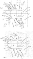
- Fig. 1 shows a rough schematic representation of a device 1 for forming containers.
- This device has a rotatable support, such as a blowing wheel 2, on which a plurality of blowing stations 4 is arranged.
- These blowing stations 4 serve in each case for forming plastic preforms 10 to plastic containers.
- the individual blow molding stations each have blow molds which form a cavity in their interior which serves to expand the plastic preforms 10.
- the individual blow molding stations also have stretch rods which stretch the plastic preforms in their longitudinal direction, so that the device is a stretch blow molding machine.
- Fig. 2a shows a valve block according to the prior art.
- This valve block in this case has a blowing nozzle 72 which is applied to the plastic preforms 10 in order to pressurize them for their expansion with compressed air.
- the reference numeral 110 refers to a housing of the valve block, which is designated in its entirety by 120.
- Reference numeral 118 denotes a muffler.
- Fig. 2b shows a more detailed illustration of a valve block according to the prior art. It can be seen that supply channels 104 are present here, via which the blown air can be supplied to the plastic preform 10.
- the reference numeral 106 refers to a movable piston which can be moved here along the double arrow P, for example by using guide curves or the like. Via an annular space 102, the blown air for the expansion of the plastic preforms 10 can be supplied by means of a valve (not shown).
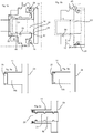
- Fig. 3 shows a representation of a device 20 for the pneumatic control of the blowing pressure or a control block 20.
- This control block has a control piston 14 which is mounted displaceably along the longitudinal axis L.
- this control piston 14 is mounted displaceably in a cylinder 12 or a guide body 12.
- the control piston 14 is at least partially formed of a metal and in particular it is formed on its outer periphery 14a of a metal.
- the cylinder or the guide cylinder 12 is formed here from a plastic. In this cylinder 12 also guide surfaces 42 and 44 are integrated, which are also made here of plastic.
- the reference numeral 28 denotes a sealing device, which is also arranged here in a circumferential groove 23 of the cylinder 12.
- the reference numeral 16 designates a main flow path, which when the valve is open (in Fig. 3 when the closed position is drawn) leads from an admission space 30 to an outlet 31. Along this main flow path 16, the blown air reaches the plastic preforms (not shown).
- the reference numeral 32 denotes openings which are distributed uniformly in the circumferential direction of the control piston 14 and in particular arranged in the cylinder 12 here.
- a surface 17 arranged on the outer circumference 14a of the control piston 14 lies opposite the individual openings 32 in a closed state of the valve.
- the reference numeral 46 refers to a sealing surface of the control piston 14, which the outlet channel 31 in the in Fig. 3 covering position shown.
- the sealing surface 46 also causes a seal of the main flow path 16.
- the control piston is in a closed state of the valve to a sealing body 36, which is formed here at the left end of the cylinder 12.
- this sealing body 36 is formed integrally with the cylinder 36. This is with reference to the FIGS. 8a-8d explained in more detail.
- this sealing surface 46 is disposed on the control piston 14, more specifically, a portion of the end face of the control piston forms the said sealing surface 46.
- the control piston 14, which is designed here as a metal piston (but can also be made of ceramic) is thus in an additional guide cylinder, ie the cylinder 12, which is made here of plastic out.
- the cylinder also serves to seal the end face of the control piston 14 against the metallic valve block. If the control piston 14 is made of ceramic, can be dispensed with the additional guide cylinder 12.
- the guide cylinder can in turn be accommodated in a receiving body such as a sleeve (not shown).
- the control piston 14 is mounted directly on the integrated into the cylinder 12 guide points or Passungs mismessern 42, 44.
- the guide piston has a cavity 52 in its interior, or is turned out hollow inside.
- the reference numeral 34 denotes a stopper screw. This stop screw 34 serves on the one hand to form a stop for the backward movement of the control piston 14 and on the other hand, this stop screw 34 also serves as a cover for reducing the control air / dead volume, since the stopper screw 34, the cavity 52 is covered.
- the air openings 32 are arranged uniformly on the circumference of the control piston 14, and thereby cause the piston is symmetrically flowed by the compressed air.
- the reference numeral 15 refers to a trained as an inclined surface Drfit Structure, which is arranged at the lower end of the control piston 14.
- This urging surface or oblique surface 15, which is formed circumferentially here, also serves as an urging surface.
- An urging surface is understood to mean a surface or a section which, by its (in particular geometrical) arrangement, is suitable for generating a force acting on a gaseous medium acting in the longitudinal direction of the control piston. Thus, the urging surface deflects a force acting on them preferred. As soon as the space 30 surrounding the control piston 14 is subjected to compressed air, this pressure also acts on this urging surface 15 and thus causes the control piston 14 to act in Fig. 3 pushed back to the right.
- the device 20 is designed so that in the presence of a control pressure in the control chamber 26 of, for example, 10 bar of the control piston 14 in the in Fig. 3 shown, left position. Only when the control pressure in the control chamber 26 is no longer present, the control piston 14 due to the blowing pressure in Fig. 3 move to the right. The control pressure acts on the control surface 24 of the control piston 14th
- Fig. 4 shows a further embodiment of a device 20.
- a seal against the outlet 31 by means of a plastic disc 50 which has the same size areas A1, A2 on the printed pages. In this way, equal areas arise when sealing.
- the control piston 14 is mounted here on guide belts 62, 64, which are inserted in the cylinder 12. Again, a cavity 52 is provided to save weight and also in Fig. 3 illustrated stop screw. As in the case of Fig. 3 Here, too, a symmetrical flow of the control piston 12 is achieved by the uniform circumferentially arranged openings 32.
- the control piston can be made here of metal, ceramic, if necessary. Also as magnesium or hard rubber.
- the cylinder or the guide is advantageously made of metal or ceramic here.
- Fig. 5a shows a further embodiment for illustrating the guide.
- a seal 29 is provided on the control piston 14, which serves to seal the 10 bar pressure chamber.
- Another seal 28 is disposed in the cylinder 12.
- the control piston 14 is guided here exclusively on the small diameter D1 of the cylinder 12.
- the reference numerals 42 and 44 relate again to the respective guide surfaces.
- Fig. 5b shows a further embodiment of a device.
- a seal 29 is also provided in the control piston 12 and a seal 28 in the cylinder 12.
- the piston guide takes place here both on the small diameter D1, as well as on the large diameter D2 of the control piston 12.
- the reference numerals 42 and 45 refer to the respective guide surfaces.
- the guide surfaces are formed such that a purely metallic contact of the guide surfaces is avoided, so that, for example, the guide between a plastic surface and a metal surface or between two plastic surfaces.
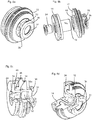
- FIGS. 6a to 6c show three possible embodiments of a control piston 14.
- the piston is in each case made of two components.
- the piston in this case has a base body 14b.
- a sealing surface 25 made of plastic is arranged on the main body 14b.
- a sealing surface 27 is provided, which is an area of the main body 14b engages behind. In this case, this sealing surface 27 is vulcanized onto the base body 14b.
- the sealing surface 25 is also made of plastic and vulcanized with a base portion 21 in the main body 14b.
- Fig. 7a shows a detailed view illustrating the sealing surfaces.
- the control piston has here a recess 18, so that the supplied blowing air flows to the control piston in full.
- the sealing takes place here via the two surfaces A1 and A2.
- a plastic disc 50 is also provided here, against which the control piston 14 rests over the surface A1 for the purpose of sealing.
- the two surfaces A1 and A2 are the same size here.
- Fig. 7b shows a further embodiment for illustrating the seal.
- the control piston 14 here again has a recess 19 which, however, here is designed as a circumferential groove.
- the reference numeral 46 refers in both representations to the formed on the control piston 14 sealing surface.
- the two surfaces A1 and A2 are parallel to each other and particularly preferably offset in the longitudinal direction of the control piston 14 to each other.
- FIGS. 8a-8d show various representations of the cylinder 12, partly with the control piston 14 arranged therein FIG. 8a it can be seen that on the cylinder 12, a sealing body 36 is formed. More precisely, this sealing body 36 is arranged integrally on the cylinder 12. In the Fig. 8a not shown) inner surface of the sealing body 36 serves to seal the valve when a corresponding end face of the control piston 14 bears against it.
- the sealing body 36 is arranged by means of webs 38 on the base body of the cylinder 12 and between these, the individual openings 32, via which the blowing air can enter, formed.
- Fig. 8b shows a representation of the in Fig. 8a
- the control piston 14 is formed here in two parts and more precisely has a stop screw 34 which is screwed into a corresponding cavity of the control piston.
- the reference numeral 48 refers to a circumferential projection which is arranged on the cylinder 12.
- the urging surface 15 can be seen, which causes when exposed to compressed air, that the control piston in Fig. 8b relative to the cylinder 12 moves to the left.
- Fig. 8c shows a sectional view of the cylinder 12 with disposed therein control piston 14. It can be seen that the circumferential projection 48 in a recess 49 which is formed in the control piston 14, can penetrate.
- the reference numeral 36a designates the above-mentioned inner surface of the sealing body 36 which together with the end face 14c of the control piston 14 (or a -particularly annular - part of this end face 14c serves to seal the valve.
- Fig. 8d shows a further sectional view, in which in particular the end face 14c of the control piston 14 is visible
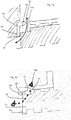
- Fig. 9a shows another possible embodiment of a device.
- the control piston 14 is not in the 3 and 4 shown oblique surfaces 15. Therefore, originating from the annular space 30 Queranströmung on the control piston 14 causes no axial force, because the pressure is not present at the end face of the piston. For this reason, another (inevitable) control by means of two additional valves 82 and 84, which act here as pilot valves, is provided.
- a first pilot valve 82 it is possible to apply an annular surface 86 with control air, in order in this way the control piston 14 in Fig. 7 along the arrow P1 to move to its rear position (ie to the right). In this position, the working pressure air can flow into the plastic preform.
- control piston 14 can be achieved by a second pilot valve 84, which in turn acts on the control chamber 26 with compressed air and in this way a movement of the control piston 14 in Fig. 7 to the left, ie counter to the direction of arrow P1 causes.
- a combination of an additional piston and an air spring is used.
- This system pressure of 10 bar works here in the Control chamber 26 and causes in this way, that the control piston is pressed into the front position and thus closes the "P1" valve.
- the pilot valve 82 By means of the pilot valve 82, the annular surface 86 is supplied with control air and thereby the control piston 14 can be moved to the rear position and in this way, the working pressure air can flow into the plastic preform.
- the device has an additional piston.
- the working pressure air eg at 40 bar
- valve 84 By means of a pilot valve 84, the circular area or control surface 24 is supplied with control air and thereby the control piston 14 is moved to the front position and in this way closes the valve.
- the return of the valve it would also be possible for the return of the valve to be done in other ways, for example by a spring.
- an electromagnet could be provided which moves the control piston 14 in the figures to the right or opens the valve.
- the device or have the means for the pneumatic control of the blowing pressure on the pressure transducer.
- pressure transducer include the pressure transducer itself and the transmitter in a housing. So that the pressure sensor can be positioned closer to the process, it is proposed here to form the pressure sensor in two parts and, in particular, to provide the evaluation electronics at a distance from the actual pressure sensor.
- the transmitter and the pressure transducer themselves as different components and in particular carried out separately.
- the present invention is therefore further directed to a device according to the preamble of claim 1, which device comprises a pressure transducer for determining at least one pressure occurring in the device and wherein an evaluation of this pressure transducer is arranged separately from the actual pressure transducer.
- the pressure sensor is arranged directly on the unit for the pneumatic control of the blowing pressure.
- the pressure sensor can be positioned directly in the pressure chamber, for example, the annular chamber 30 acted upon by the blowing pressure, and the transmitter outside. In this way, the control block can be made more compact overall.
- valves such as the pilot valves 82 and 84 by (not shown) air channels in the control block.
- the in Fig. 2a arranged silencer 118 is arranged in a non-aseptic area. This procedure is particularly suitable for aseptic execution of the control block.
- these valves are provided in particular redundantly and in particular or intended only for safe opening of the device in case of failure of a pilot valve. It would be possible to install two (redundant) pilot valves on an outlet valve, which is advantageous for a space-saving solution for a safe opening.
- Fig. 11a and 11b show two possible embodiments of an aseptic pilot valve 90.
- the reference numerals 92 and 94 each refer to a signal terminal, in Fig. 10b the two openings 96 and 98 on working connections, the reference numeral 95 to a connection for a silencer and the reference numeral 93 to a supply port (in particular for air).
- the signal connection 92 and 94 can be designed, for example, as an IP67 suitable plug or as a gap-free potted cable.
- the air connections (for air supply and silencer) can be separated for each pilot valve as well as shared.
Landscapes
- Engineering & Computer Science (AREA)
- Manufacturing & Machinery (AREA)
- Mechanical Engineering (AREA)
- Actuator (AREA)
- Blow-Moulding Or Thermoforming Of Plastics Or The Like (AREA)
- Processing And Handling Of Plastics And Other Materials For Molding In General (AREA)
Description
- Die vorliegende Erfindung bezieht sich auf eine Vorrichtung gemäß Anspruch 1 zur Blasformung von Behältnissen. Derartige Vorrichtungen sind aus dem Stand der Technik seit langem bekannt. Dabei werden üblicherweise erwärmte Kunststoffvorformlinge mit Druckluft beaufschlagt um auf diese Weise zu Kunststoffbehältnissen umgeformt zu werden. Üblicherweise weisen derartigen Vorrichtungen zum Umformen der Kunststoffvorformlinge zu Kunststoffbehältnissen ein Blasrad auf, an dem eine Vielzahl von Blasstationen angeordnet ist. Diese Blasstationen wiederum bilden hierbei Hohlräume aus, innerhalb derer die Kunststoffvorformlinge expandiert werden.
- Die Beaufschlagung der Kunststoffvorformlinge mit Druckluft erfolgt dabei üblicherweise mittels Blasdüsen. Der zur Expansion der Kunststoffvorformlinge nötige Blasdruck wird dabei üblicherweise mittels Ventilblöcken zur Verfügung gestellt. Aus dem Stand der Technik sind diverse Ausgestaltungen dieser Ventilblöcke bzw. Ventilmechanismen bekannt.
- Die
EP 1 328 396 B1 beschreibt eine Blasmaschine mit einem an der Blasvorrichtung angebrachten Steuerventil zur Steuerung der Blasluft. Dabei ist ein die Blasdüse zumindest über einen Teil ihrer Höhe ringartig umschließender Ventilkörper vorgesehen. Ein Niederdruckventil, ein Hochdruckventil sowie ein Entlüftungsventil sind über den Umfang des Ventilträgers verteilt angeordnet und durch Bohrungen im Ventilträger mit der Blasdüse verbunden. - Aus der
EP 1 271 029 B1 , die den Gegenstand des Oberbegriffs des Anspruchs 1 offenbart, ist eine Vorrichtung zur Blasformung von Behältern bekannt. Diese Vorrichtung weist dabei eine Einrichtung zur pneumatischen Steuerung des Blasdrucks auf und diese Einrichtung weist einen in einem Zylinder geführten Steuerkolben auf, der in Richtung einer Längsachse gelagert ist. Dabei ist dieser Steuerkolben zumindest bereichsweise aus einem Kunststoff ausgebildet. Durch diese bereichsweise Ausbildung des Steuerkolbens aus Kunststoff wird ein metallischer Kontakt mit der Wandung des Zylinders vermieden. Auf diese Weise können separate Führungsbänder vermieden werden. Daneben weist dieser Steuerkolben aus Kunststoff auch ein geringeres Gewicht und eine verringerte Massenträgheit auf.
Diese Vorrichtung arbeitet zwar zufriedenstellend, es hat sich jedoch gezeigt, dass die auf diese Weise hergestellten Steuerkolben teilweise einem erhöhten Verschleiß unterliegen.
Der vorliegenden Erfindung liegt daher Aufgabe zugrunde, eine Vorrichtung zur Blasformung von Behältern zur Verfügung zu stellen, welche eine erhöhte Lebensdauer aufweist. Dies wird erfindungsgemäß durch den Gegenstand des unabhängigen Anspruchs erreicht. Vorteilhafte Ausführungsformen und Ausbildungen sind Gegenstand der Unteransprüche. - Bei einer ersten Ausgestaltung weist die vorliegende Vorrichtung auf einem Blasrad angeordnete Blasstationen zur Blasformung von Behältern aus einem thermoplastischen Material auf. Weiterhin weist die Vorrichtung eine Einrichtung zur pneumatischen Steuerung eines Blasdrucks auf, wobei die Einrichtung zur pneumatischen Steuerung einen in einem Zylinder geführten Steuerkolben aufweist, der in Richtung einer Kolbenlängsachse verschieblich gelagert ist und bei der durch den Zylinder - im Folgenden auch als Führungszylinder oder allgemein Führungskörper bezeichnet - hindurch ein vom Steuerkolben verschließbarer Hauptströmungsweg verläuft. Weiterhin ist der Steuerkolben mit einer Steuerfläche versehen, die einem Steuerraum des Zylinders zugewandt ist und die zur Übertragung einer Steuerkraft auf den Steuerkolben ausgebildet ist.
- Eine Umfangswandung des Steuerkolbens blockiert in wenigstens einer Position des Steuerkolbens den Hauptströmungsweg. Mit anderen Worten ist insbesondere der Hauptströmungsweg in einem geschlossenen Zustand der Einrichtung von einer Umfangswandung des Steuerkolbens blockiert.
- Während im Stand der Technik üblicherweise nur die Stirnflächen des Steuerkolbens den Hauptströmungsweg für die Blasluft blockieren, wird hier vorgeschlagen, dass zusätzlich zumindest auch die Umfangswandung den Hauptströmungsweg blockiert. Bei den Behältern handelt es sich insbesondere um Kunststoffvorformlinge bzw. die daraus zu formenden Kunststoffbehälter. Unter einem Blockieren wird dabei verstanden, dass die besagte Umfangswandung dem Hauptströmungspfad im Weg steht. Dabei muss die Umfangswandung den Hauptströmungspfad nicht notwendigerweise abdichten. Vielmehr ist es möglich, dass die Abdichtung über eine Stirnfläche des Steuerkolbens bzw. einen Teil dieser Stirnfläche erfolgt.
- Vorteilhaft ist dabei ein Einlass für die Druckluft in einer Umfangswandung des Zylinders angeordnet. Vorteilhaft ist ein Einlass für die Blasluft bzw. Druckluft gegenüber dem Auslass in der Längsrichtung des Steuerkolbens versetzt, d.h. höhenversetzt. Im Stand der Technik wird üblicherweise durch eine Stirnfläche des Steuerkolbens sowohl der Einlass für die Druckluft als auch der Auslass für die Druckluft abgedeckt bzw. blockiert. Im Rahmen der hier vorliegenden Offenbarung wird vorgeschlagen, dass zumindest entweder der Einlass für die Blasluft oder der Auslass für die Blasluft, bevorzugt der Einlass für die Blasluft von einer Umfangswandung des Steuerkolbens in einem geschlossenen Zustand der Einrichtung bzw. des Ventils blockiert bzw. (zumindest teilweise) versperrt wird. Der Vorteil dieser Ausführungsform besteht darin, dass so eine gleichmäßigere Anströmung des Steuerkolbens in dessen Umfangsrichtung möglich ist.
- Eine weitere Ausgestaltung einer vorliegenden Vorrichtung weist auf einem Blasrad angeordnete Blasstationen zur Blasformung von Behältern aus einem thermoplastischen Material auf. Weiterhin weist die Vorrichtung eine Einrichtung zur pneumatischen Steuerung eines Blasdrucks auf, wobei die Einrichtung zur pneumatischen Steuerung einen in einem Zylinder geführten Steuerkolben aufweist, der in Richtung einer Kolbenlängsachse verschieblich gelagert ist und bei der durch den Zylinder hindurch ein vom Steuerkolben verschließbarer Hauptströmungsweg verläuft. Weiterhin ist der Steuerkolben mit einer Steuerfläche versehen, die einem Steuerraum des Zylinders zugewandt ist und die zur Übertragung einer Steuerkraft auf den Steuerkolben ausgebildet ist.
- Der Steuerkolben ist mindestens bereichsweise aus einem Metall oder einer Keramik ausgebildet.
- Es wird daher vorgeschlagen, ein pneumatisch gesteuertes Ventil zur Verfügung zu stellen, dessen Steuerkolben bereichsweise aus einem Metall oder einer Keramik ausgebildet ist. Durch diese Ausbildung des Steuerkolbens aus Metall oder Keramik kann die Widerstandsfähigkeit des Steuerkolbens und damit eines beweglichen Ventilelements erhöht werden und auf diese Weise auch die Lebensdauer der Einrichtung d.h. des Ventils in seiner Gesamtheit.
- Bevorzugt ist der Hauptströmungsweg derart angeordnet, dass bei einer Absenkung des Steuerdrucks der Steuerkolben durch den einwirkenden Hochdruck in Richtung der Kolbenlängsachse verschoben wird. Es wäre jedoch auch möglich, dass die Verschiebung des Steuerkolbens nicht unter Einfluss des Hochdrucks bzw. Blasdrucks erfolgt sondern in anderer Weise, etwa durch ein zusätzliches Pilotventil, eine Feder, magnetische Kräfte oder dergleichen.
- Vorteilhaft weisen die einzelnen Blasstationen jeweils Blasformen auf, innerhalb derer Kunststoffvorformlinge zu den Kunststoffbehältnissen expandierbar sind.
- Erfindungsgemäß weist der Zylinder zumindest teilweise aus einem Kunststoff gefertigte Führungsflächen zum Führen des Steuerkolbens auf. Auf diese Weise wird ein metallischer Kontakt mit dem Steuerkolben vermieden.
- Bei einer weiteren vorteilhaften Ausführungsform ist der Hauptströmungsweg in dem Zylinder angeordnet. Während im Falle der
EP 1 271 029 der Hauptströmungsweg unterhalb des Kolbens angeordnet ist wird hier vorgeschlagen, dass der Hauptströmungsweg in dem Zylinder bzw. einer Umfangswand des Zylinders selbst befindlich ist. Daher wird bei dieser Ausführungsform der besagte Hauptströmungsweg nicht durch eine Bodenfläche des Steuerkolbens sondern durch den Außenumfang des Steuerkolbens abgedeckt bzw. abgedichtet. - Nach einer weiteren vorteilhaften Ausführungsform weist die Einrichtung zur pneumatischen Steuerung eine Dichtfläche zum Verschließen des Hauptströmungswegs auf und diese Dichtfläche ist an einem Außenumfang des Zylinders angeordnet. Die Stirnfläche des Kolbens wird dabei nicht als Aussenumfang verstanden Damit wird vorgeschlagen, dass der Steuerkolben als zumindest teilweise metallischer oder keramischer Kolben und bevorzugt als Metallkolben oder Keramikkolben ausgeführt ist, der bevorzugt in einer Kunststoffbuchse geführt ist wobei vorteilhaft in diese Kunststoffbuchse auch die besagten Dichtflächen integriert sind. Vorzugsweise sind dabei die Dichtfläche und die besagte Führung für den Steuerkolben zweiteilig ausgebildet.
- Bei einer weiteren vorteilhaften Ausführungsform ist der Steuerkolben vollständig aus einem Metall ausgebildet. Vorteilhaft ist der Steuerkolben aus Aluminium ausgebildet.
- Bei einer weiteren bevorzugten Ausführungsform weist der Steuerkolben einen Hohlraum auf. Dieser Hohlraum kann dabei im Inneren des Steuerkolbens ausgeführt sein. Mit anderen Worten kann hier zur Gewichtserleichterung der Kolben innen hohl ausgeführt beispielsweise ausgedreht sein.
- Bei einer weiteren vorteilhaften Ausführungsform ist in dem Zylinder wenigstens eine Dichtungseinrichtung zum Abdichten der Bewegung des Steuerkolbens (entlang dessen Längsrichtung) angeordnet. Genauer gesagt handelt sich hierbei um Dichtflächen, die zum Abdichten der Bewegung des Steuerkolbens ausgebildet sind.
- Bei einer weiteren vorteilhaften Ausführungsform weist die Vorrichtung einen den Steuerkolben in dessen Umfangsrichtung (bzw. um dessen Bewegungsrichtung herum) umgebenden Beaufschlagungsraum auf, der insbesondere mit Blasluft beaufschlagbar ist. Dies bedeutet, dass im Gegensatz zum Stand der Technik der Steuerkolben nicht ausschließlich in seiner Längsrichtung mit dem Druck beaufschlagt wird sondern voll umfänglich von der Seite her. Auf diese Weise ist eine symmetrische Anströmung des Steuerkolbens möglich. Vorteilhaft weist die Vorrichtung wenigstens zwei, bevorzugt wenigstens drei und bevorzugt eine Vielzahl von gleichmäßig am Umfang des Steuerkolbens angeordneten Luftöffnungen auf. In einem geschlossenen Zustand der Einrichtung bzw. des Ventils werden diese Luftöffnungen vorteilhaft durch den Aussenumfang des Steuerkolbens verschlossen.
- Bei einer weiteren vorteilhaften Ausführungsform weist der Steuerkolben eine Drängfläche auf, welche den Steuerkolben bei Beaufschlagung mit Druckluft - insbesondere in der radialen Richtung des Steuerkolbens d.h. einer zu der Längsrichtung des Steuerkolbens senkrecht stehenden Richtung - entlang der Kolbenlängsachse verschiebt. Bei dem Stand der Technik kann der Steuerkolben unmittelbar durch die in Längsrichtung auftreffende Luft verschoben werden. Da, wie oben erwähnt, bei der hier dargestellten Ausführungsform die Luft nicht mit einer Längsrichtung auf den Steuerkolben trifft sondern seitwärts, ist vorteilhaft die genannte Drängfläche vorgesehen. Dabei kann es sich beispielsweise um eine am Kolbenende angeordnete Schrägflache handeln, die bei der Beaufschlagung mit Druckluft in einer radialen bzw. senkrecht zu der Bewegungsrichtung des Steuerkolbens stehenden Richtung eine Bewegung des Steuerkolbens in seiner Gesamtheit bewirkt. Daneben kann die besagte Drängfläche an einem Außenumfang des Steuerkolbens angeordnet sein. Dies wird unter Bezugnahme auf die Figuren genauer erläutert.
- Bei einer weiteren bevorzugten Ausführungsform ist der Steuerkolben mehrteilig und insbesondere zweiteilig ausgebildet. Dabei kann eines dieser mehreren bzw. beiden Teile des Steuerkolbens beispielsweise aus einem Metall und das andere aus Kunststoff gefertigt sein.
- Bei einer weiteren vorteilhaften Ausführungsform ist an dem Steuerkolben ein Anschlagmittel, wie beispielsweise eine Anschlagsschraube, angeordnet. Diese Anschlagsschraube dient dabei zum einen als Anschlag und zum anderen vorteilhaft auch als Deckel zur Reduzierung des Steuerlufttotraumvolumens.
- Bei einer bevorzugten Ausführungsform ist der Steuerkolben aus einem Material hergestellt, welches aus einer Gruppe ausgewählt ist, welche Metalle, Keramik, Magnesium, Hartgummi und der gleichen enthält. Die Führung bzw. der Führungszylinder ist, wie oben erwähnt, vorteilhaft aus einem Kunststoff hergestellt.
- Es wäre jedoch auch möglich, dass der Führungszylinder aus Metall oder Keramik ausgebildet ist. Auch wäre es möglich, dass der Führungszylinder mehrteilig aufgebaut ist und beispielsweise einen aus Kunststoff gefertigten Führungskörper zum Führen des Steuerkolbens aufweist sowie einen Grundkörper, der diesen Führungskörper trägt. Dieser Grundkörper kann dabei auch den Steuerraum ausbilden.
- Bei einer weiteren vorteilhaften Ausführungsform weist der Steuerkolben ein Kunststoffelement auf. Auf diese Weise ist es möglich, dass sich der Steuerkolben aus einem metallischen Anteil und einem Kunststoffanteil zusammensetzt. So wäre es beispielsweise möglich, dass in einem Hohlraum des Steuerkolbens ein Kunststoffsegment untergebracht ist. Auch wäre möglich, dass eine Dichtfläche am Ende des Steuerkolbens aus Kunststoff ausgebildet ist. Daneben wäre es möglich, dass ein Kunststoffelement in einen ansonsten aus Metall bestehenden Steuerkolben eingearbeitet ist.
- Weitere Vorteile und Ausführungsformen ergeben sich aus den beigefügten Zeichnungen:
Darin zeigen: - Fig. 1
- eine schematische Darstellung einer Vorrichtung zum Blasformen von Behältern;
- Fig. 2a
- einen Ventilblock nach dem Stand der Technik;
- Fig. 2b
- eine Detaildarstellung des Ventilblocks aus
Figur 2a ; - Fig. 3
- eine Darstellung einer Einrichtung zur pneumatischen Steuerung des Blasdrucks;
- Fig. 4
- eine weitere Ausführungsform einer Einrichtung;
- Fig. 5a
- eine Detaildarstellung einer Einrichtung;
- Fig. 5b
- eine weitere Detaildarstellung einer Einrichtung;
- Fig. 6a - 6c
- drei mögliche Varianten für Steuerkolben;
- Fig. 7a - 7b
- zwei Teilansichten einer Vorrichtung;
- Fig. 8a - 8d
- vier Darstellungen einer vorteilhaften Ausführungsform eines Ventils
- Fig.9a
- eine weitere Ausführungsform einer Einrichtungsform zur pneumatischen Steuerung;
- Fig. 9b
- eine weitere Ausführungsform einer Einrichtung zur Steuerung des Blasdrucks;
- Fig. 10
- eine weitere Ausführungsform einer Einrichtung zur Steuerung des Blasdrucks;
- Fig. 11a, 11b
- zwei Darstellungen eines aseptischen Pilotventils.
-
Fig. 1 zeigt eine grob schematische Darstellung einer Vorrichtung 1 zum Umformen von Behältnissen. Diese Vorrichtung weist dabei einen drehbaren Träger, wie ein Blasrad 2 auf, an dem eine Vielzahl von Blasstationen 4 angeordnet ist. Diese Blasstationen 4 dienen dabei jeweils zum Umformen von Kunststoffvorformlingen 10 zu Kunststoffbehältnissen. Zu diesem Zweck weisen die einzelnen Blasstationen jeweils Blasformen auf, die in ihrem Inneren einen Hohlraum ausbilden, der zur Expansion der Kunststoffvorformlinge 10 dient. Vorzugsweise weisen die einzelnen Blasstationen auch Reckstangen auf, welche die Kunststoffvorformlinge in deren Längsrichtung dehnen, so dass es sich bei der Vorrichtung um eine Streckblasmaschine handelt. -
Fig. 2a zeigt einen Ventilblock nach dem Stand der Technik. Dieser Ventilblock weist dabei eine Blasdüse 72 auf, welche an die Kunststoffvorformlinge 10 angelegt wird, um diese zu deren Expansion mit Druckluft zu beaufschlagen. Das Bezugszeichen 110 bezieht sich auf ein Gehäuse des Ventilblocks, der in seiner Gesamtheit mit 120 bezeichnet ist. Das Bezugszeichen 118 kennzeichnet einen Schalldämpfer. -
Fig. 2b zeigt eine detailliertere Darstellung eines Ventilblocks nach dem Stand der Technik. Man erkennt, dass hier Zuführkanäle 104 vorhanden sind, über welche die Blasluft dem Kunststoffvorformling 10 zugeführt werden kann. Das Bezugszeichen 106 bezieht sich auf einen beweglichen Kolben, der hier beispielsweise durch Verwendung von Führungskurven oder dergleichen entlang des Doppelpfeils P bewegt werden kann. Über einen Ringraum 102 kann mittels eines (nicht gezeigten) Ventils die Blasluft zur Expansion der Kunststoffvorformlinge 10 zugeführt werden. -
Fig. 3 zeigt eine Darstellung einer Einrichtung 20 zur pneumatischen Steuerung des Blasdrucks bzw. eines Steuerblocks 20. Dieser Steuerblock weist dabei einen Steuerkolben 14 auf, der entlang der Längsachse L verschieblich gelagert ist. Im Einzelnen ist dieser Steuerkolben 14 in einem Zylinder 12 bzw. einem Führungskörper 12 verschieblich gelagert. - Der Steuerkolben 14 ist dabei wenigstens abschnittsweise aus einem Metall ausgebildet und insbesondere ist er an seinem Außenumfang 14a aus einem Metall ausgebildet. Der Zylinder bzw. der Führungszylinder 12 ist hier aus einem Kunststoff ausgebildet. In diesen Zylinder 12 sind auch Führungsflächen 42 und 44 integriert, die hier ebenfalls aus Kunststoff gefertigt sind. Das Bezugszeichen 28 kennzeichnet eine Dichtungseinrichtung, die hier ebenfalls in einer umlaufenden Nut 23 des Zylinders 12 angeordnet ist. Das Bezugszeichen 16 kennzeichnet einen Hauptströmungsweg, der bei geöffnetem Ventil (in
Fig. 3 ist die geschlossene Stellung gezeichnet) von einem Beaufschlagungsraum 30 zu einem Auslass 31 führt. Entlang dieses Hauptströmungswegs 16 gelangt die Blasluft zu den (nicht dargestellten) Kunststoffvorformlingen. - Das Bezugszeichen 32 kennzeichnet Öffnungen, welche hier gleichmäßig in Umfangsrichtung des Steuerkolbens 14 verteilt und insbesondere in dem Zylinder 12 angeordnet sind. Eine am Aussenumfang 14a des Steuerkolbens 14 angeordnete Fläche 17 liegt den einzelnen Öffnungen 32 in einem geschlossenen Zustand des Ventils gegenüber..
- Das Bezugszeichen 46 bezieht sich auf eine Dichtfläche des Steuerkolbens 14, welche den Austrittskanal 31 in der in
Fig. 3 gezeigten Position abdeckt. Damit bewirkt die Dichtfläche 46 auch eine Abdichtung des Hauptströmungswegs 16. Genauer gesagt liegt der Steuerkolben in einem geschlossenen Zustand des Ventils an einem Dichtkörper 36 an, der hier an dem linken Ende des Zylinders 12 ausgebildet ist. Vorteilhaft ist dieser Dichtkörper 36 einteilig mit dem Zylinder 36 ausgebildet. Dies wird unter Bezugnahme auf dieFiguren 8a - 8d genauer erläutert. - Bei der in
Fig. 3 gezeigten Darstellung ist diese Dichtfläche 46 an dem Steuerkolben 14 angeordnet, genauer bildet ein Abschnitt der Stirnfläche des Steuerkolbens die besagte Dichtfläche 46 aus. Der Steuerkolben 14, der hier als Metallkolben ausgeführt ist (jedoch auch aus Keramik gefertigt sein kann) wird damit in einem zusätzlichen Führungszylinder, d.h. dem Zylinder 12, der hier aus Kunststoff gefertigt ist, geführt. Der Zylinder dient gleichzeitig zur Abdichtung der Stirnfläche des Steuerkolbens 14 gegen den metallischen Ventilblock. Falls der Steuerkolben 14 aus Keramik besteht, kann auf den zusätzlichen Führungszylinder 12 verzichtet werden. Der Führungszylinder kann wiederum in einem Aufnahmekörper wie einer Hülse (nicht gezeigt) aufgenommen sein. - Der Steuerkolben 14 ist direkt auf den in den Zylinder 12 integrierten Führungsstellen bzw. Passungsdurchmessern 42, 44 gelagert. Zur Gewichtseinsparung weist der Führungskolben in seinem Inneren einen Hohlraum 52 auf, bzw. ist innen hohl ausgedreht. Das Bezugszeichen 34 kennzeichnet eine Anschlagschraube. Diese Anschlagschraube 34 dient einerseits dazu, um einen Anschlag für die Rückwärtsbewegung des Steuerkolbens 14 auszubilden und andererseits dient diese Anschlagschraube 34 auch als Deckel zur Reduzierung des Steuerluft-/ Totvolumens, da durch diese Anschlagschraube 34 der Hohlraum 52 abgedeckt wird. Die Luftöffnungen 32 sind gleichmäßig am Umfang des Steuerkolbens 14 angeordnet, und bewirken dadurch, dass der Kolben symmetrisch von der Druckluft angeströmt wird.
- Das Bezugszeichen 15 bezieht sich auf eine als Schrägfläche ausgebildete Drängfläche, die am unteren Ende des Steuerkolbens 14 angeordnet ist. Diese Drängfläche bzw. Schrägfläche 15, die hier umlaufend ausgebildet ist, dient dabei auch als Drängfläche. Unter einer Drängfläche wird eine Fläche bzw. ein Abschnitt verstanden, der durch seine (insbesondere geometrische) Anordnung geeignet ist, bei Beaufschlagung mit einem gasförmigen Medium eine Kraft zu erzeugen, die hier in der Längsrichtung des Steuerkolbens wirkt. Damit lenkt die Drängfläche eine auf sie wirkende Kraft bevorzugt um. Sobald der den Steuerkolben 14 umgebende Raum 30 mit Druckluft beaufschlagt wird, wirkt dieser Druck auch auf diese Drängfläche 15 und bewirkt damit, dass der Steuerkolben 14 in
Fig. 3 nach rechts zurückgedrängt wird. - Dabei ist jedoch die Einrichtung 20 so ausgelegt, dass bei Vorhandensein eines Steuerdrucks in dem Steuerraum 26 von beispielsweise 10 bar der Steuerkolben 14 in der in
Fig. 3 gezeigten, linken Position ist. Erst wenn der Steuerdruck in dem Steuerraum 26 nicht mehr vorhanden ist, kann sich der Steuerkolben 14 aufgrund des Blasdrucks inFig. 3 nach rechts bewegen. Der Steuerdruck wirkt dabei auf die Steuerfläche 24 des Steuerkolbens 14 -
Fig. 4 zeigt eine weitere Ausführungsform einer Einrichtung 20. Bei dieser Ausführungsform erfolgt eine Abdichtung gegenüber dem Auslass 31 mit Hilfe einer Kunststoffscheibe 50, die gleich große Flächen A1, A2 auf den Druckseiten aufweist. Auf diese Weise ergeben sich gleich große Flächen beim Abdichten. - Der Steuerkolben 14 ist hier auf Führungsbändern 62, 64 gelagert, welche in dem Zylinder 12 eingelegt sind. Auch hier ist wieder ein Hohlraum 52 zur Gewichtseinsparung vorgesehen sowie die auch in
Fig. 3 dargestellte Anschlagschraube. Wie auch im Fall vonFig. 3 wird auch hier eine symmetrische Anströmung des Steuerkolbens 12 durch die gleichmäßige am Umfang angeordneten Öffnungen 32 erreicht. - Der Steuerkolben kann hier aus Metall, Keramik, ggfs. auch als Magnesium oder Hartgummi hergestellt sein. Der Zylinder bzw. die Führung ist hier vorteilhaft aus Metall oder Keramik hergestellt.
-
Fig. 5a zeigt eine weitere Ausführungsform zur Veranschaulichung der Führung. Hier ist an dem Steuerkolben 14 eine Dichtung 29 vorgesehen, welche zur Abdichtung des 10 bar Druckraums dient. Eine weitere Dichtung 28 ist in dem Zylinder 12 angeordnet. Der Steuerkolben 14 wird hier ausschließlich auf dem kleinen Durchmesser D1 von dem Zylinder 12 geführt. Die Bezugszeichen 42 und 44 beziehen sich wieder auf die jeweiligen Führungsflächen. -
Fig. 5b zeigt eine weitere Ausführungsform einer Einrichtung. In diesem Fall ist ebenfalls eine Dichtung 29 in dem Steuerkolben 12 vorgesehen sowie eine Dichtung 28 in dem Zylinder 12. Die Kolbenführung erfolgt hier jedoch sowohl auf dem kleinen Durchmesser D1, als auch auf dem großen Durchmesser D2 des Steuerkolbens 12. Die Bezugszeichen 42 und 45 beziehen sich auf die jeweiligen Führungsflächen. - Vorzugsweise sind bei allen Ausführungsformen die Führungsflächen derart ausgebildet, dass ein rein metallischer Kontakt der Führungsflächen vermieden wird, so dass beispielsweise die Führung zwischen einer Kunststofffläche und einer Metallfläche oder zwischen zwei Kunststoffflächen erfolgt.
- Die
Figuren 6a bis 6c zeigen drei mögliche Ausgestaltungen eines Steuerkolbens 14. Bei diesen Ausführungsformen ist der Kolben jeweils aus zwei Komponenten ausgebaut. Im Einzelnen weist der Kolben hierbei einen Grundkörper 14b auf. Bei der inFig. 6a gezeigten Ausgestaltung ist an dem Grundkörper 14b eine Dichtfläche 25 aus Kunststoff angeordnet. Bei der inFig. 6b gezeigten Variante ist eine Dichtfläche 27 vorgesehen, welche einen Bereich des Grundkörpers 14b hintergreift. Dabei ist diese Dichtfläche 27 auf den Grundkörper 14b aufvulkanisiert. - Bei der in
Fig. 6c gezeigten Ausführungsform ist die Dichtfläche 25 ebenfalls aus Kunststoff hergestellt und mit einem Grundabschnitt 21 in den Grundkörper 14b einvulkanisiert. -
Fig. 7a zeigt eine Detaildarstellung zur Veranschaulichung der Dichtflächen. Dabei blockiert auch hier eine Umfangswandung 14a des Steuerkolbens 14 den Hauptströmungsweg 16. Der Steuerkolben weist jedoch hier eine Ausnehmung 18 auf, so dass die zugeführte Blasluft den Steuerkolben vollumfänglich anströmt. Die Abdichtung erfolgt hier über die beiden Flächen A1 und A2. Genauer gesagt ist auch hier eine Kunststoffscheibe 50 vorgesehen, an der der Steuerkolben 14 über die Fläche A1 zum Zweck der Abdichtung anliegt. Bei den gezeigten Ausführungsformen ist es daher auch nicht notwendig, dass der Steuerkolben die Kunststoffführung über seinen Umfang an allen Stellen berührt. Bei der inFig. 7a gezeigten Ausführungsform ist damit gewährleistet, dass jeweils eine metallische oder keramische Oberfläche gegenüber einer Kunststofffläche abdichtet. Bevorzugt sind auch hier die beiden Flächen A1 und A2 gleich groß. -
Fig. 7b zeigt eine weitere Ausführungsform zur Veranschaulichung der Abdichtung. Auch hier sind wieder zwei Dichtflächen A1 und A2 vorgesehen, über welche die Abdichtung erfolgt. Der Steuerkolben 14 weist hier wiederum eine Ausnehmung 19 auf, welche hier jedoch als umlaufende Nut ausgebildet ist. Das Bezugszeichen 46 bezieht sich in beiden Darstellungen auf die an dem Steuerkolben 14 ausgebildete Dichtfläche. Bevorzugt sind die beiden Flächen A1 und A2 parallel zueinander und besonders bevorzugt in der Längsrichtung des Steuerkolbens 14 zueinander versetzt. - Die
Figuren 8a - 8d zeigen verschiede Darstellungen des Zylinders 12, teilweise mit dem darin angeordneten Steuerkolben 14. InFigur 8a erkennt man, dass an dem Zylinder 12 ein Dichtkörper 36 ausgebildet ist. Genauer gesagt ist dieser Dichtkörper 36 einteilig an dem Zylinder 12 angeordnet. Die (inFig. 8a nicht gezeigte) Innenfläche des Dichtkörpers 36 dient zum Abdichten des Ventils, wenn sich eine entsprechende Stirnfläche des Steuerkolbens 14 daran anlegt. Der Dichtkörper 36 ist mittels Stegen 38 an dem Grundkörper des Zylinders 12 angeordnet und zwischen diesen sind die einzelnen Öffnungen 32, über welche die Blasluft eintreten kann, ausgebildet. -
Fig. 8b zeigt eine Darstellung des inFig 8a gezeigten Zylinders 12 sowie des darin beweglich anzuordnenden Steuerkolbens 14. Man erkennt, dass der Steuerkolben 14 hier insgesamt zweiteilig ausgebildet ist und genauer eine Anschlagschraube 34 aufweist, welche in einen entsprechenden Hohlraum des Steuerkolbens eingeschraubt wird. Das Bezugszeichen 48 bezieht sich auf einen umlaufenden Vorsprung, der an dem Zylinder 12 angeordnet ist. Weiterhin ist auch hier wieder die Drängfläche 15 erkennbar, die bei Beaufschlagung mit Druckluft bewirkt, dass sich der Steuerkolben inFig. 8b gegenüber dem Zylinder 12 nach links bewegt. -
Fig. 8c zeigt eine Schnittdarstellung des Zylinders 12 mit darin angeordnetem Steuerkolben 14. Man erkennt, dass der umlaufende Vorsprung 48 in eine Ausnehmung 49, welche in dem Steuerkolben 14 ausgebildet ist, eindringen kann. Das Bezugszeichen 36a kennzeichnet die oben erwähnte Innenfläche des Dichtkörpers 36 welche gemeinsam mit der Stirnfläche 14c des Steuerkolbens 14 (bzw. einem -insbesondere ringförmigen - Teil dieser Stirnfläche 14c zum Abdichten des Ventils dient.Fig. 8d zeigt eine weitere Schnittdarstellung, bei der insbesondere auch die Stirnfläche 14c des Steuerkolbens 14 sichtbar ist -
Fig. 9a zeigt eine weitere mögliche Ausführungsform einer Einrichtung. Bei dieser Ausführungsform weist der Steuerkolben 14 nicht die in denFig. 3 und 4 gezeigten Schrägflächen 15 auf. Daher bewirkt die aus den Ringraum 30 stammende Queranströmung auf den Steuerkolben 14 keine axiale Kraft, weil der Druck nicht an der Stirnseite des Kolbens ansteht. Aus diesem Grund ist eine weitere (zwangsläufige) Ansteuerung mit Hilfe zweier zusätzlicher Ventile 82 und 84, die hier als Pilotventile fungieren, vorgesehen. Mittels eines ersten Pilotventils 82 ist es möglich, eine Ringfläche 86 mit Steuerluft zu beaufschlagen, um auf diese Weise den Steuerkolben 14 inFig. 7 entlang des Pfeils P1 in seine hintere Stellung (d.h. nach rechts) zu bewegen. In dieser Position kann die Arbeitsdruckluft in den Kunststoffvorformling strömen. Die Bewegung des Steuerkolbens 14 kann durch ein zweites Pilotventil 84 erreicht werden, welches wiederum den Steuerraum 26 mit Druckluft beaufschlagt und auf diese Weise eine Bewegung des Steuerkolbens 14 inFig. 7 nach links, d. h. entgegen der Pfeilrichtung P1 bewirkt. - Bei der in
Fig. 9b gezeigten Ausführungsform wird eine Kombination aus einem zusätzlichen Kolben und einer Luftfeder verwendet. Dieser Systemdruck von 10 bar wirkt hier in dem Steuerraum 26 und bewirkt auf diese Weise, dass der Steuerkolben in die vordere Position gedrückt wird und auf diese Weise das "P1"-Ventil schließt. Mittels des Pilotventils 82 wird die Ringfläche 86 mit Steuerluft beaufschlagt und dadurch kann der Steuerkolben 14 in die hintere Stellung bewegt werden und auf diese Weise kann die Arbeitsdruckluft in den Kunststoffvorformling einströmen. - Bei der in
Fig. 10 gezeigten Ausführungsform weist die Einrichtung einen zusätzlichen Kolben auf. Bei dieser Ausführungsform wirkt auf die Ringfläche 86 permanent die Arbeitsdruckluft (z. B. mit 40 bar), sodass der Steuerkolben 14 in die hintere Position gedrückt wird und auf diese Weise das Ventil geöffnet ist (d. h. hier kann die Arbeitsdruckluft in den Kunststoffvorformling einströmen). - Mittels eines Pilotventils 84 wird die Kreisfläche bzw. Steuerfläche 24 mit Steuerluft beaufschlagt und dadurch wird der Steuerkolben 14 in die vordere Stellung bewegt und auf diese Weise schließt das Ventil. Es wäre jedoch auch möglich, dass die Rückstellung des Ventils in anderer Weise, etwa durch eine Feder erfolgt. Auch könnte ein Elektromagnet vorgesehen sein, der den Steuerkolben 14 in den Figuren nach rechts bewegt bzw. das Ventil öffnet.
- Bei einer vorteilhaften Ausführungsform weist die Vorrichtung bzw. weisen die Einrichtungen zur pneumatischen Steuerung des Blasdrucks Druckaufnehmer auf. Üblicherweise beinhalten derartige Druckaufnehmer den Druckaufnehmer selbst und die Auswerteelektronik in einem Gehäuse. Damit der Druckaufnehmer näher am Prozess positioniert werden kann, wird hier vorgeschlagen, den Druckaufnehmer zweiteilig auszubilden und insbesondere die Auswerteelektronik beabstandet von dem eigentlichen Druckaufnehmer vorzusehen. Vorteilhaft werden daher die Auswerteelektronik und der Druckaufnehmer selbst als unterschiedliche Bauteile und insbesondere getrennt voneinander ausgeführt.
- Die vorliegende Erfindung ist daher weiterhin auf eine Vorrichtung nach dem Oberbegriff von Anspruch 1 gerichtet, wobei diese Vorrichtung einen Druckaufnehmer zum Bestimmen wenigstens eines in der Einrichtung auftretenden Drucks aufweist und wobei eine Auswerteelektronik dieses Druckaufnehmers getrennt von dem eigentlichen Druckaufnehmer angeordnet ist. Bevorzugt ist der Druckaufnehmer unmittelbar an der Einheit zur pneumatischen Steuerung des Blasdrucks angeordnet.
- Mit anderen Worten kann der Druckaufnehmer direkt in der Druckkammer, beispielsweise der durch den Blasdruck beaufschlagten Ringkammer 30 positioniert werden und die Auswerteelektronik außerhalb. Auf diese Weise kann der Steuerblock insgesamt kompakter gebaut werden.
- Bei einer weiteren vorteilhaften Ausführungsform, welche jedoch auch unabhängig von der Eingangs beschriebenen Offenbarung Anwendung finden kann, erfolgt die Entlüftung der Ventile, wie beispielsweise der Pilotventile 82 und 84 durch (nicht gezeigte) Luftkanäle im Steuerblock. Auf diese Weise ist es möglich, den in
Fig. 2a dargestellten Schalldämpfer 118 in einem nicht aseptischen Bereich anzuordnen. Diese Vorgehensweise eignet sich insbesondere bei einer aseptischen Ausführung des Steuerblocks. - Bei einer weiteren vorteilhaften Ausführungsform weist die Einrichtung zur pneumatischen Steuerung zwei Pilotventile auf und weiterhin weist der Steuerblock zwei Auslauss-(exhaust) Ventile auf. Diese Ventile sind dabei jedoch insbesondere redundant vorgesehen und insbesondere bzw. nur zum sicheren Öffnen der Einrichtung bei Ausfall eines Pilotventils gedacht. Dabei wäre es möglich, zwei (redundante) Pilotventile an einem Auslassventil zu verbauen, was vorteilhaft für eine platzsparende Lösung für ein sicheres Öffnen ist.
-
Fig. 11a und 11b zeigen zwei mögliche Ausführungen eines aseptischen Pilotventils 90. Dabei beziehen sich die Bezugszeichen 92 und 94 auf je einen Signalanschluss, inFig. 10b die beiden Öffnungen 96 und 98 auf Arbeitsanschlüsse, das Bezugszeichen 95 auf einen Anschluss für einen Schalldämpfer und das Bezugszeichen 93 auf einen Zuführanschluss (insbesondere für Luft). Dabei wäre es auch möglich, ein oder mehrere der in den vorangegangen Figuren gezeigten Pilotventile als eine Einheit auszuführen und beispielsweise in Kunststoff zu vergießen. Der Signalanschluss 92 und 94 kann dabei beispielsweise als IP67 geeigneter Stecker oder auch als spaltfrei vergossenes Kabel ausgeführt sein. Die Luftanschlüsse (für Luftzufuhr und Schalldämpfer) können sowohl für jedes Pilotventil getrennt, als auch gemeinsam nutzbar ausgeführt sein. -
- 1
- Vorrichtung
- 2
- Blasrad
- 4
- Blasstationen
- 10
- Kunststoffvorformlinge
- 12
- (Führungs-)Zylinder, Führungskörper
- 14
- Steuerkolben
- 14a
- Aussenumfang des Steuerkolbens
- 14b
- Grundkörper
- 14c
- Stirnfläche des Steuerkolbens
- 15
- Drängfläche
- 16
- Hauptströmungsweg
- 17
- Fläche des Steuerkolbens
- 18
- Ausnehmung
- 19
- nutförmige Ausnehmung
- 20
- Steuerblock, Einrichtung
- 21
- Grundabschnitt
- 23
- Nut
- 24
- Steuerfläche
- 25
- Dichtfläche
- 26
- Steuerraum
- 27
- Dichtfläche
- 28
- Dichtungseinrichtung
- 29
- Dichtung
- 30
- Beaufschlagungsraum, Ringraum
- 31
- Auslass, Austrittskanal
- 32
- Öffnungen
- 34
- Anschlagschraube
- 36
- Dichtkörper
- 36a
- Innenfläche des Dichtkörpers
- 38
- Stege
- 42, 44, 45
- Führungsflächen, Passungsdurchmesser
- 46
- Dichtfläche
- 48
- (ringförmiger) Vorsprung
- 49
- Ausnehmung
- 52
- Hohlraum
- 62
- erstes Pilotenventil
- 62, 64
- Führungsbänder
- 72
- Blasdüse
- 82, 84
- (Pilot)-Ventile
- 86
- Ringfläche
- 90
- aseptisches Pilotventil
- 92, 94
- Signalanschluss
- 93
- Zuführanschluss
- 95
- Anschluss für Schalldämpfer
- 96, 98
- Arbeitsanschlüsse
- 102
- Ringraum (Stand der Technik)
- 104
- Zuführkanäle (Stand der Technik)
- 106
- beweglicher Kolben (Stand der Technik)
- 110
- Gehäuse
- 118
- Schalldämpfer
- 120
- Ventilblock (Stand der Technik)
- A1, A2
- große Flächen
- D1
- kleiner Durchmesser
- D2
- großer Durchmesser
- L
- Längsachse
- P
- Doppelpfeil
- P1
- Pfeil
- P2
- Pfeilrichtung
Claims (10)
- Vorrichtung (1) mit auf einem Blasrad (2) angeordneten Blasstationen (4) zur Blasformung von Behältern (10) aus einem thermoplastischen Material, mit einer Einrichtung (20) zur pneumatischen Steuerung eines Blasdruckes, wobei die Einrichtung (20) zur pneumatischen Steuerung einen in einem Zylinder (12) geführten Steuerkolben (14) aufweist, der in Richtung einer Kolbenlängsachse (L) verschieblich gelagert ist und bei der durch den Zylinder (12) hindurch ein vom Steuerkolben (14) verschließbarer Hauptströmungsweg (16) verläuft, sowie bei der der Steuerkolben (14) mit einer Steuerfläche (24) versehen ist, die einem Steuerraum (26) des Zylinders (12) zugewandt ist und die zur Übertragung einer Steuerkraft auf den Steuerkolben (14) ausgebildet ist, wobei der Steuerkolben (14) mindestens bereichsweise aus einem Metall oder einer Keramik ausgebildet ist,
dadurch gekennzeichnet, dass
der Zylinder (12) aus einem Kunststoff gefertigte Führungsflächen (42, 44) zum Führen des Steuerkolbens (14) aufweist, durch die Führungsflächen (42, 44) ein metallischer Kontakt des Steuerkolbens (14) mit dem Zylinder verhindert ist. - Vorrichtung nach Anspruch 1,
dadurch gekennzeichnet, dass
der Hauptströmungsweg (16) derart angeordnet ist, dass bei einer Absenkung des Steuerdrucks der Steuerkolben (14) durch den einwirkenden Hochdruck in Richtung der Kolbenlängsachse (L) verschoben wird. - Vorrichtung (1) nach wenigstens einem der vorangegangenen Ansprüche,
dadurch gekennzeichnet, dass
der Steuerkolben (14) vollständig aus einem Metall oder aus Keramik ausgebildet ist. - Vorrichtung (1) nach wenigstens einem der vorangegangenen Ansprüche,
dadurch gekennzeichnet, dass
der Steuerkolben (14) einen Hohlraum (52) aufweist. - Vorrichtung (1) nach wenigstens einem der vorangegangenen Ansprüche,
dadurch gekennzeichnet, dass
in dem Zylinder (12) wenigstens eine Dichtungseinrichtung (28) zum Abdichten der Bewegung des Steuerkolbens (14) angeordnet ist. - Vorrichtung (1) nach wenigstens einem der vorangegangenen Ansprüche,
dadurch gekennzeichnet, dass
die Vorrichtung (1) einen den Steuerkolben (14) in dessen Umfangsrichtung umgebenden Beaufschlagungsraum (30) aufweist, der mit Blasluft beaufschlagbar ist. - Vorrichtung (1) nach wenigstens einem der vorangegangenen Ansprüche,
dadurch gekennzeichnet, dass
der Steuerkolben (14) eine Drängfläche (15) aufweist, welche den Steuerkolben (14) bei Beaufschlagung mit Druckluft entlang der Kolbenlängsachse (L) verschieben kann. - Vorrichtung (1) nach wenigstens einem der vorangegangenen Ansprüche,
dadurch gekennzeichnet, dass
der Steuerkolben (14) mehrteilig und insbesondere zweiteilig ausgebildet ist. - Vorrichtung (1) nach wenigstens einem der vorangegangenen Ansprüche,
dadurch gekennzeichnet, dass
der Steuerkolben (14) eine Anschlagschraube (34) aufweist. - Vorrichtung (1) nach wenigstens einem der vorangegangenen Ansprüche,
dadurch gekennzeichnet, dass
der Steuerkolben (14) ein Kunststoffelement (25, 27) aufweist.
Priority Applications (1)
| Application Number | Priority Date | Filing Date | Title |
|---|---|---|---|
| EP18194200.4A EP3431252A1 (de) | 2010-12-01 | 2011-12-01 | Vorrichtung zur blasformung von behältnissen |
Applications Claiming Priority (1)
| Application Number | Priority Date | Filing Date | Title |
|---|---|---|---|
| DE102010052903A DE102010052903A1 (de) | 2010-12-01 | 2010-12-01 | Vorrichtung zur Blasformung von Behältnissen |
Related Child Applications (1)
| Application Number | Title | Priority Date | Filing Date |
|---|---|---|---|
| EP18194200.4A Division EP3431252A1 (de) | 2010-12-01 | 2011-12-01 | Vorrichtung zur blasformung von behältnissen |
Publications (3)
| Publication Number | Publication Date |
|---|---|
| EP2460639A2 EP2460639A2 (de) | 2012-06-06 |
| EP2460639A3 EP2460639A3 (de) | 2014-01-15 |
| EP2460639B1 true EP2460639B1 (de) | 2018-10-10 |
Family
ID=45217354
Family Applications (2)
| Application Number | Title | Priority Date | Filing Date |
|---|---|---|---|
| EP11191606.0A Active EP2460639B1 (de) | 2010-12-01 | 2011-12-01 | Vorrichtung zur Blasformung von Behältnissen |
| EP18194200.4A Pending EP3431252A1 (de) | 2010-12-01 | 2011-12-01 | Vorrichtung zur blasformung von behältnissen |
Family Applications After (1)
| Application Number | Title | Priority Date | Filing Date |
|---|---|---|---|
| EP18194200.4A Pending EP3431252A1 (de) | 2010-12-01 | 2011-12-01 | Vorrichtung zur blasformung von behältnissen |
Country Status (4)
| Country | Link |
|---|---|
| US (1) | US9050751B2 (de) |
| EP (2) | EP2460639B1 (de) |
| CN (1) | CN102529076B (de) |
| DE (1) | DE102010052903A1 (de) |
Families Citing this family (3)
| Publication number | Priority date | Publication date | Assignee | Title |
|---|---|---|---|---|
| KR101328244B1 (ko) * | 2013-02-05 | 2013-11-14 | 파카코리아 주식회사 | 블로우 몰딩 머신용 블로잉 밸브 |
| DE102013111029A1 (de) * | 2013-10-04 | 2015-04-09 | Krones Ag | Blasformmaschine mit Blaskolben mit schräg angeordneten Verbindungsleitungen |
| DE102013111950A1 (de) | 2013-10-30 | 2015-04-30 | Krones Ag | Umformvorrichtung zum Umformen von Kunststoffvorformlingen zu Kunststoffbehältnissen |
Citations (11)
| Publication number | Priority date | Publication date | Assignee | Title |
|---|---|---|---|---|
| US4267861A (en) | 1979-11-05 | 1981-05-19 | Rk Industries | Plural modular fluid transfer valves |
| US4644969A (en) | 1984-08-20 | 1987-02-24 | Oki Electric Industry Co., Ltd. | Water control valve with pneumatic actuator |
| EP0882921A2 (de) | 1997-06-04 | 1998-12-09 | Furon Company | Kompaktes Ventil mit Rollmembranventilkörper |
| DE19956575A1 (de) | 1999-11-24 | 2001-05-31 | Berghof Laborprodukte Gmbh | Hochdruckventil für aggressive Medien |
| EP1271029A1 (de) | 2001-06-29 | 2003-01-02 | SIG Corpoplast GmbH & Co. KG | Vorrichtung zur pneumatischen Steuerung |
| DE10131556A1 (de) | 2001-06-29 | 2003-01-16 | Sig Corpoplast Gmbh & Co Kg | Vorrichtung zur pneumatischen Steuerung |
| EP1293329A1 (de) | 2001-09-15 | 2003-03-19 | SIG Corpoplast GmbH & Co. KG | Vorrichtung zur Blasformung von Behältern |
| DE20305232U1 (de) | 2003-04-01 | 2003-05-28 | Festo Ag & Co | Ventilblock |
| EP2078890A1 (de) | 2008-01-11 | 2009-07-15 | Festo AG & Co. KG | Ventileinheit |
| EP2105641A2 (de) | 2008-03-26 | 2009-09-30 | Festo AG & Co. KG | Ventileinheit und damit ausgestattete Streckblasvorrichtung |
| EP2335904A1 (de) | 2009-12-21 | 2011-06-22 | FESTO AG & Co. KG | Ventil |
Family Cites Families (4)
| Publication number | Priority date | Publication date | Assignee | Title |
|---|---|---|---|---|
| FR2804059B1 (fr) * | 2000-01-20 | 2002-08-30 | Sidel Sa | Machine de soufflage de recipients comportant des moyens d'orientation des preformes dans le moule de soufflage |
| DE20018500U1 (de) | 2000-10-28 | 2001-12-13 | Krones Ag | Blasmaschine |
| CN100560338C (zh) * | 2006-12-08 | 2009-11-18 | 上海紫江企业集团股份有限公司 | 容器瓶的拉伸吹塑成型方法 |
| ATE518643T1 (de) * | 2008-02-05 | 2011-08-15 | Seitz Eugen Ag | Vorrichtung zum einblasen von druckluft in eine blasform |
-
2010
- 2010-12-01 DE DE102010052903A patent/DE102010052903A1/de active Pending
-
2011
- 2011-12-01 US US13/308,911 patent/US9050751B2/en active Active
- 2011-12-01 EP EP11191606.0A patent/EP2460639B1/de active Active
- 2011-12-01 EP EP18194200.4A patent/EP3431252A1/de active Pending
- 2011-12-01 CN CN201110393161.8A patent/CN102529076B/zh active Active
Patent Citations (11)
| Publication number | Priority date | Publication date | Assignee | Title |
|---|---|---|---|---|
| US4267861A (en) | 1979-11-05 | 1981-05-19 | Rk Industries | Plural modular fluid transfer valves |
| US4644969A (en) | 1984-08-20 | 1987-02-24 | Oki Electric Industry Co., Ltd. | Water control valve with pneumatic actuator |
| EP0882921A2 (de) | 1997-06-04 | 1998-12-09 | Furon Company | Kompaktes Ventil mit Rollmembranventilkörper |
| DE19956575A1 (de) | 1999-11-24 | 2001-05-31 | Berghof Laborprodukte Gmbh | Hochdruckventil für aggressive Medien |
| EP1271029A1 (de) | 2001-06-29 | 2003-01-02 | SIG Corpoplast GmbH & Co. KG | Vorrichtung zur pneumatischen Steuerung |
| DE10131556A1 (de) | 2001-06-29 | 2003-01-16 | Sig Corpoplast Gmbh & Co Kg | Vorrichtung zur pneumatischen Steuerung |
| EP1293329A1 (de) | 2001-09-15 | 2003-03-19 | SIG Corpoplast GmbH & Co. KG | Vorrichtung zur Blasformung von Behältern |
| DE20305232U1 (de) | 2003-04-01 | 2003-05-28 | Festo Ag & Co | Ventilblock |
| EP2078890A1 (de) | 2008-01-11 | 2009-07-15 | Festo AG & Co. KG | Ventileinheit |
| EP2105641A2 (de) | 2008-03-26 | 2009-09-30 | Festo AG & Co. KG | Ventileinheit und damit ausgestattete Streckblasvorrichtung |
| EP2335904A1 (de) | 2009-12-21 | 2011-06-22 | FESTO AG & Co. KG | Ventil |
Also Published As
| Publication number | Publication date |
|---|---|
| EP2460639A3 (de) | 2014-01-15 |
| EP2460639A2 (de) | 2012-06-06 |
| US20120141621A1 (en) | 2012-06-07 |
| US9050751B2 (en) | 2015-06-09 |
| CN102529076A (zh) | 2012-07-04 |
| EP3431252A1 (de) | 2019-01-23 |
| DE102010052903A1 (de) | 2012-06-06 |
| CN102529076B (zh) | 2014-07-23 |
Similar Documents
| Publication | Publication Date | Title |
|---|---|---|
| EP2105641B1 (de) | Ventileinheit und damit ausgestattete Streckblasvorrichtung | |
| EP2253451B1 (de) | Vorrichtung zum Blasformen von Kunststoffvorformlingen mit reduziertem Totvolumen und entsprechende Anlage | |
| EP0236464B1 (de) | Nietsetzwerkzeug | |
| WO2010092038A2 (de) | Vorrichtung zur einstellung des gasdrucks in einem kraftfahrzeugreifen | |
| EP3024633A1 (de) | Ventilanordnung | |
| EP2460639B1 (de) | Vorrichtung zur Blasformung von Behältnissen | |
| EP2167303B1 (de) | Ventileinrichtung für hohlkörperblasmaschinen und verfahren zum einblasen von drukluft in ein blasvolumen | |
| DE102019107140A1 (de) | Düsenanordnung mit Druckreguliervorrichtung sowie Granuliervorrichtung | |
| EP3348376B1 (de) | Umformvorrichtung zum umformen von kunststoffvorformlingen zu kunststoffbehältnissen | |
| DE102014000814B4 (de) | Ventileinheit | |
| EP0465955B1 (de) | Pneumatisch betätigbarer Linearantrieb für Punktschweiss-Automaten | |
| EP2053260B1 (de) | Kupplungskraftverstärker | |
| DE2334413A1 (de) | Pneumatischer stellantrieb | |
| EP0849005B1 (de) | Pneumatischer Klopfer | |
| DE102016125137A1 (de) | Mehrstellungszylinder | |
| DE102009059829B4 (de) | Ventileinrichtung | |
| DE102008025775A1 (de) | Vorrichtung zum Expandieren von Behältnissen mit radial zustellbarer Dichtung | |
| EP2505336A1 (de) | Antriebseinrichtung für den Blasdorn einer Blasformmaschine | |
| DE202004019495U1 (de) | Durch Druckmitteldruck, insbesondere pneuamtisch, betätigte Kolben-Zylinder-Einheit, bei welcher ein mit einer Kolbenstange verbundener Kolben durch Druckmittelbeaufschlagung linear bewegbar ist, z.B. druckmittelbetätigbare Kniehebelspannvorrichtung, insbesondere für den Karosseriebau der Kfz-Industrie | |
| EP3119595B1 (de) | Vorrichtung zum abdichten und aufpumpen aufblasbarer gegenstände | |
| DE4012968C2 (de) | Pneumatisch betätigbarer Linearantrieb für Punktschweiß-Automaten | |
| DE10120323C1 (de) | Elektropneumatisches Regelventil mit einer Dichtungsanordnung | |
| EP1416166B1 (de) | Endlagengedämpfter Pneumatikzylinder | |
| EP4082751B1 (de) | Verfahren zum betreiben einer ventileinheit und ventileinheit | |
| EP1731246A1 (de) | Vorrichtung zum Herstellen einer Vielfalt von Formteilen aus Pulver. |
Legal Events
| Date | Code | Title | Description |
|---|---|---|---|
| PUAI | Public reference made under article 153(3) epc to a published international application that has entered the european phase |
Free format text: ORIGINAL CODE: 0009012 |
|
| AK | Designated contracting states |
Kind code of ref document: A2 Designated state(s): AL AT BE BG CH CY CZ DE DK EE ES FI FR GB GR HR HU IE IS IT LI LT LU LV MC MK MT NL NO PL PT RO RS SE SI SK SM TR |
|
| AX | Request for extension of the european patent |
Extension state: BA ME |
|
| PUAL | Search report despatched |
Free format text: ORIGINAL CODE: 0009013 |
|
| AK | Designated contracting states |
Kind code of ref document: A3 Designated state(s): AL AT BE BG CH CY CZ DE DK EE ES FI FR GB GR HR HU IE IS IT LI LT LU LV MC MK MT NL NO PL PT RO RS SE SI SK SM TR |
|
| AX | Request for extension of the european patent |
Extension state: BA ME |
|
| RIC1 | Information provided on ipc code assigned before grant |
Ipc: F16K 31/124 20060101ALN20131211BHEP Ipc: B29C 49/42 20060101AFI20131211BHEP |
|
| 17P | Request for examination filed |
Effective date: 20140715 |
|
| RBV | Designated contracting states (corrected) |
Designated state(s): AL AT BE BG CH CY CZ DE DK EE ES FI FR GB GR HR HU IE IS IT LI LT LU LV MC MK MT NL NO PL PT RO RS SE SI SK SM TR |
|
| STAA | Information on the status of an ep patent application or granted ep patent |
Free format text: STATUS: EXAMINATION IS IN PROGRESS |
|
| 17Q | First examination report despatched |
Effective date: 20180202 |
|
| GRAP | Despatch of communication of intention to grant a patent |
Free format text: ORIGINAL CODE: EPIDOSNIGR1 |
|
| STAA | Information on the status of an ep patent application or granted ep patent |
Free format text: STATUS: GRANT OF PATENT IS INTENDED |
|
| RIC1 | Information provided on ipc code assigned before grant |
Ipc: B29C 49/78 20060101ALI20180531BHEP Ipc: F16K 31/124 20060101ALN20180531BHEP Ipc: B29C 49/58 20060101ALI20180531BHEP Ipc: B29C 49/42 20060101AFI20180531BHEP |
|
| INTG | Intention to grant announced |
Effective date: 20180626 |
|
| GRAS | Grant fee paid |
Free format text: ORIGINAL CODE: EPIDOSNIGR3 |
|
| GRAA | (expected) grant |
Free format text: ORIGINAL CODE: 0009210 |
|
| STAA | Information on the status of an ep patent application or granted ep patent |
Free format text: STATUS: THE PATENT HAS BEEN GRANTED |
|
| AK | Designated contracting states |
Kind code of ref document: B1 Designated state(s): AL AT BE BG CH CY CZ DE DK EE ES FI FR GB GR HR HU IE IS IT LI LT LU LV MC MK MT NL NO PL PT RO RS SE SI SK SM TR |
|
| REG | Reference to a national code |
Ref country code: GB Ref legal event code: FG4D Free format text: NOT ENGLISH |
|
| RIN1 | Information on inventor provided before grant (corrected) |
Inventor name: GELTINGER, FLORIAN Inventor name: VOTH, KLAUS Inventor name: HANDSCHUH, EDUARD |
|
| REG | Reference to a national code |
Ref country code: AT Ref legal event code: REF Ref document number: 1050709 Country of ref document: AT Kind code of ref document: T Effective date: 20181015 Ref country code: CH Ref legal event code: EP |
|
| REG | Reference to a national code |
Ref country code: IE Ref legal event code: FG4D Free format text: LANGUAGE OF EP DOCUMENT: GERMAN |
|
| REG | Reference to a national code |
Ref country code: DE Ref legal event code: R096 Ref document number: 502011014826 Country of ref document: DE |
|
| REG | Reference to a national code |
Ref country code: NL Ref legal event code: MP Effective date: 20181010 |
|
| REG | Reference to a national code |
Ref country code: LT Ref legal event code: MG4D |
|
| PG25 | Lapsed in a contracting state [announced via postgrant information from national office to epo] |
Ref country code: NL Free format text: LAPSE BECAUSE OF FAILURE TO SUBMIT A TRANSLATION OF THE DESCRIPTION OR TO PAY THE FEE WITHIN THE PRESCRIBED TIME-LIMIT Effective date: 20181010 |
|
| PG25 | Lapsed in a contracting state [announced via postgrant information from national office to epo] |
Ref country code: NO Free format text: LAPSE BECAUSE OF FAILURE TO SUBMIT A TRANSLATION OF THE DESCRIPTION OR TO PAY THE FEE WITHIN THE PRESCRIBED TIME-LIMIT Effective date: 20190110 Ref country code: ES Free format text: LAPSE BECAUSE OF FAILURE TO SUBMIT A TRANSLATION OF THE DESCRIPTION OR TO PAY THE FEE WITHIN THE PRESCRIBED TIME-LIMIT Effective date: 20181010 Ref country code: LT Free format text: LAPSE BECAUSE OF FAILURE TO SUBMIT A TRANSLATION OF THE DESCRIPTION OR TO PAY THE FEE WITHIN THE PRESCRIBED TIME-LIMIT Effective date: 20181010 Ref country code: LV Free format text: LAPSE BECAUSE OF FAILURE TO SUBMIT A TRANSLATION OF THE DESCRIPTION OR TO PAY THE FEE WITHIN THE PRESCRIBED TIME-LIMIT Effective date: 20181010 Ref country code: HR Free format text: LAPSE BECAUSE OF FAILURE TO SUBMIT A TRANSLATION OF THE DESCRIPTION OR TO PAY THE FEE WITHIN THE PRESCRIBED TIME-LIMIT Effective date: 20181010 Ref country code: PL Free format text: LAPSE BECAUSE OF FAILURE TO SUBMIT A TRANSLATION OF THE DESCRIPTION OR TO PAY THE FEE WITHIN THE PRESCRIBED TIME-LIMIT Effective date: 20181010 Ref country code: BG Free format text: LAPSE BECAUSE OF FAILURE TO SUBMIT A TRANSLATION OF THE DESCRIPTION OR TO PAY THE FEE WITHIN THE PRESCRIBED TIME-LIMIT Effective date: 20190110 Ref country code: FI Free format text: LAPSE BECAUSE OF FAILURE TO SUBMIT A TRANSLATION OF THE DESCRIPTION OR TO PAY THE FEE WITHIN THE PRESCRIBED TIME-LIMIT Effective date: 20181010 Ref country code: IS Free format text: LAPSE BECAUSE OF FAILURE TO SUBMIT A TRANSLATION OF THE DESCRIPTION OR TO PAY THE FEE WITHIN THE PRESCRIBED TIME-LIMIT Effective date: 20190210 |
|
| PG25 | Lapsed in a contracting state [announced via postgrant information from national office to epo] |
Ref country code: SE Free format text: LAPSE BECAUSE OF FAILURE TO SUBMIT A TRANSLATION OF THE DESCRIPTION OR TO PAY THE FEE WITHIN THE PRESCRIBED TIME-LIMIT Effective date: 20181010 Ref country code: RS Free format text: LAPSE BECAUSE OF FAILURE TO SUBMIT A TRANSLATION OF THE DESCRIPTION OR TO PAY THE FEE WITHIN THE PRESCRIBED TIME-LIMIT Effective date: 20181010 Ref country code: GR Free format text: LAPSE BECAUSE OF FAILURE TO SUBMIT A TRANSLATION OF THE DESCRIPTION OR TO PAY THE FEE WITHIN THE PRESCRIBED TIME-LIMIT Effective date: 20190111 Ref country code: PT Free format text: LAPSE BECAUSE OF FAILURE TO SUBMIT A TRANSLATION OF THE DESCRIPTION OR TO PAY THE FEE WITHIN THE PRESCRIBED TIME-LIMIT Effective date: 20190210 Ref country code: AL Free format text: LAPSE BECAUSE OF FAILURE TO SUBMIT A TRANSLATION OF THE DESCRIPTION OR TO PAY THE FEE WITHIN THE PRESCRIBED TIME-LIMIT Effective date: 20181010 |
|
| REG | Reference to a national code |
Ref country code: DE Ref legal event code: R026 Ref document number: 502011014826 Country of ref document: DE |
|
| PLBI | Opposition filed |
Free format text: ORIGINAL CODE: 0009260 |
|
| PLAX | Notice of opposition and request to file observation + time limit sent |
Free format text: ORIGINAL CODE: EPIDOSNOBS2 |
|
| PG25 | Lapsed in a contracting state [announced via postgrant information from national office to epo] |
Ref country code: DK Free format text: LAPSE BECAUSE OF FAILURE TO SUBMIT A TRANSLATION OF THE DESCRIPTION OR TO PAY THE FEE WITHIN THE PRESCRIBED TIME-LIMIT Effective date: 20181010 Ref country code: CZ Free format text: LAPSE BECAUSE OF FAILURE TO SUBMIT A TRANSLATION OF THE DESCRIPTION OR TO PAY THE FEE WITHIN THE PRESCRIBED TIME-LIMIT Effective date: 20181010 |
|
| REG | Reference to a national code |
Ref country code: CH Ref legal event code: PL |
|
| 26 | Opposition filed |
Opponent name: FESTO AG & CO. KG Effective date: 20190710 |
|
| PG25 | Lapsed in a contracting state [announced via postgrant information from national office to epo] |
Ref country code: RO Free format text: LAPSE BECAUSE OF FAILURE TO SUBMIT A TRANSLATION OF THE DESCRIPTION OR TO PAY THE FEE WITHIN THE PRESCRIBED TIME-LIMIT Effective date: 20181010 Ref country code: MC Free format text: LAPSE BECAUSE OF FAILURE TO SUBMIT A TRANSLATION OF THE DESCRIPTION OR TO PAY THE FEE WITHIN THE PRESCRIBED TIME-LIMIT Effective date: 20181010 Ref country code: SK Free format text: LAPSE BECAUSE OF FAILURE TO SUBMIT A TRANSLATION OF THE DESCRIPTION OR TO PAY THE FEE WITHIN THE PRESCRIBED TIME-LIMIT Effective date: 20181010 Ref country code: LU Free format text: LAPSE BECAUSE OF NON-PAYMENT OF DUE FEES Effective date: 20181201 Ref country code: SM Free format text: LAPSE BECAUSE OF FAILURE TO SUBMIT A TRANSLATION OF THE DESCRIPTION OR TO PAY THE FEE WITHIN THE PRESCRIBED TIME-LIMIT Effective date: 20181010 Ref country code: EE Free format text: LAPSE BECAUSE OF FAILURE TO SUBMIT A TRANSLATION OF THE DESCRIPTION OR TO PAY THE FEE WITHIN THE PRESCRIBED TIME-LIMIT Effective date: 20181010 |
|
| REG | Reference to a national code |
Ref country code: IE Ref legal event code: MM4A |
|
| GBPC | Gb: european patent ceased through non-payment of renewal fee |
Effective date: 20190110 |
|
| REG | Reference to a national code |
Ref country code: BE Ref legal event code: MM Effective date: 20181231 |
|
| PG25 | Lapsed in a contracting state [announced via postgrant information from national office to epo] |
Ref country code: SI Free format text: LAPSE BECAUSE OF FAILURE TO SUBMIT A TRANSLATION OF THE DESCRIPTION OR TO PAY THE FEE WITHIN THE PRESCRIBED TIME-LIMIT Effective date: 20181010 Ref country code: IE Free format text: LAPSE BECAUSE OF NON-PAYMENT OF DUE FEES Effective date: 20181201 |
|
| PG25 | Lapsed in a contracting state [announced via postgrant information from national office to epo] |
Ref country code: BE Free format text: LAPSE BECAUSE OF NON-PAYMENT OF DUE FEES Effective date: 20181231 |
|
| PLBB | Reply of patent proprietor to notice(s) of opposition received |
Free format text: ORIGINAL CODE: EPIDOSNOBS3 |
|
| PG25 | Lapsed in a contracting state [announced via postgrant information from national office to epo] |
Ref country code: CH Free format text: LAPSE BECAUSE OF NON-PAYMENT OF DUE FEES Effective date: 20181231 Ref country code: LI Free format text: LAPSE BECAUSE OF NON-PAYMENT OF DUE FEES Effective date: 20181231 Ref country code: GB Free format text: LAPSE BECAUSE OF NON-PAYMENT OF DUE FEES Effective date: 20190110 |
|
| PG25 | Lapsed in a contracting state [announced via postgrant information from national office to epo] |
Ref country code: MT Free format text: LAPSE BECAUSE OF FAILURE TO SUBMIT A TRANSLATION OF THE DESCRIPTION OR TO PAY THE FEE WITHIN THE PRESCRIBED TIME-LIMIT Effective date: 20181010 |
|
| PLAB | Opposition data, opponent's data or that of the opponent's representative modified |
Free format text: ORIGINAL CODE: 0009299OPPO |
|
| REG | Reference to a national code |
Ref country code: AT Ref legal event code: MM01 Ref document number: 1050709 Country of ref document: AT Kind code of ref document: T Effective date: 20181201 |
|
| R26 | Opposition filed (corrected) |
Opponent name: FESTO SE & CO. KG Effective date: 20190710 |
|
| PG25 | Lapsed in a contracting state [announced via postgrant information from national office to epo] |
Ref country code: TR Free format text: LAPSE BECAUSE OF FAILURE TO SUBMIT A TRANSLATION OF THE DESCRIPTION OR TO PAY THE FEE WITHIN THE PRESCRIBED TIME-LIMIT Effective date: 20181010 |
|
| PG25 | Lapsed in a contracting state [announced via postgrant information from national office to epo] |
Ref country code: AT Free format text: LAPSE BECAUSE OF NON-PAYMENT OF DUE FEES Effective date: 20181201 |
|
| PG25 | Lapsed in a contracting state [announced via postgrant information from national office to epo] |
Ref country code: HU Free format text: LAPSE BECAUSE OF FAILURE TO SUBMIT A TRANSLATION OF THE DESCRIPTION OR TO PAY THE FEE WITHIN THE PRESCRIBED TIME-LIMIT; INVALID AB INITIO Effective date: 20111201 Ref country code: CY Free format text: LAPSE BECAUSE OF FAILURE TO SUBMIT A TRANSLATION OF THE DESCRIPTION OR TO PAY THE FEE WITHIN THE PRESCRIBED TIME-LIMIT Effective date: 20181010 Ref country code: MK Free format text: LAPSE BECAUSE OF NON-PAYMENT OF DUE FEES Effective date: 20181010 |
|
| REG | Reference to a national code |
Ref country code: DE Ref legal event code: R100 Ref document number: 502011014826 Country of ref document: DE |
|
| PLCK | Communication despatched that opposition was rejected |
Free format text: ORIGINAL CODE: EPIDOSNREJ1 |
|
| PLBN | Opposition rejected |
Free format text: ORIGINAL CODE: 0009273 |
|
| STAA | Information on the status of an ep patent application or granted ep patent |
Free format text: STATUS: OPPOSITION REJECTED |
|
| 27O | Opposition rejected |
Effective date: 20210203 |
|
| P01 | Opt-out of the competence of the unified patent court (upc) registered |
Effective date: 20230523 |
|
| PGFP | Annual fee paid to national office [announced via postgrant information from national office to epo] |
Ref country code: IT Payment date: 20231110 Year of fee payment: 13 Ref country code: FR Payment date: 20231108 Year of fee payment: 13 Ref country code: DE Payment date: 20231031 Year of fee payment: 13 |