EP2460166B1 - Aufzugsbedieneinheit mit einem tasterelement - Google Patents
Aufzugsbedieneinheit mit einem tasterelement Download PDFInfo
- Publication number
- EP2460166B1 EP2460166B1 EP10735295.7A EP10735295A EP2460166B1 EP 2460166 B1 EP2460166 B1 EP 2460166B1 EP 10735295 A EP10735295 A EP 10735295A EP 2460166 B1 EP2460166 B1 EP 2460166B1
- Authority
- EP
- European Patent Office
- Prior art keywords
- control unit
- lift control
- shaped portion
- button
- activation
- Prior art date
- Legal status (The legal status is an assumption and is not a legal conclusion. Google has not performed a legal analysis and makes no representation as to the accuracy of the status listed.)
- Not-in-force
Links
- 230000004913 activation Effects 0.000 claims description 41
- 239000000463 material Substances 0.000 claims description 8
- 239000002184 metal Substances 0.000 claims description 7
- 230000004888 barrier function Effects 0.000 claims description 5
- 239000000919 ceramic Substances 0.000 claims description 5
- 239000004033 plastic Substances 0.000 claims description 5
- 229920003023 plastic Polymers 0.000 claims description 5
- 230000001419 dependent effect Effects 0.000 claims description 3
- 239000011343 solid material Substances 0.000 claims description 3
- 239000011324 bead Substances 0.000 claims description 2
- 241001422033 Thestylus Species 0.000 description 20
- 238000000465 moulding Methods 0.000 description 20
- 230000009471 action Effects 0.000 description 7
- 230000000694 effects Effects 0.000 description 6
- 239000000523 sample Substances 0.000 description 5
- 230000008901 benefit Effects 0.000 description 4
- 230000006378 damage Effects 0.000 description 4
- 238000010438 heat treatment Methods 0.000 description 4
- 230000007704 transition Effects 0.000 description 4
- 239000004020 conductor Substances 0.000 description 2
- 239000011521 glass Substances 0.000 description 2
- 229910001092 metal group alloy Inorganic materials 0.000 description 2
- 230000003287 optical effect Effects 0.000 description 2
- 239000004417 polycarbonate Substances 0.000 description 2
- 229920000515 polycarbonate Polymers 0.000 description 2
- 238000007142 ring opening reaction Methods 0.000 description 2
- 239000012780 transparent material Substances 0.000 description 2
- 229910000831 Steel Inorganic materials 0.000 description 1
- 230000015572 biosynthetic process Effects 0.000 description 1
- 230000008859 change Effects 0.000 description 1
- 235000019504 cigarettes Nutrition 0.000 description 1
- 238000009434 installation Methods 0.000 description 1
- 238000004519 manufacturing process Methods 0.000 description 1
- 230000007246 mechanism Effects 0.000 description 1
- 238000013021 overheating Methods 0.000 description 1
- 230000001681 protective effect Effects 0.000 description 1
- 230000009467 reduction Effects 0.000 description 1
- 239000007787 solid Substances 0.000 description 1
- 239000010959 steel Substances 0.000 description 1
Images


Classifications
-
- H—ELECTRICITY
- H01—ELECTRIC ELEMENTS
- H01H—ELECTRIC SWITCHES; RELAYS; SELECTORS; EMERGENCY PROTECTIVE DEVICES
- H01H3/00—Mechanisms for operating contacts
- H01H3/02—Operating parts, i.e. for operating driving mechanism by a mechanical force external to the switch
- H01H3/12—Push-buttons
-
- H—ELECTRICITY
- H01—ELECTRIC ELEMENTS
- H01H—ELECTRIC SWITCHES; RELAYS; SELECTORS; EMERGENCY PROTECTIVE DEVICES
- H01H2239/00—Miscellaneous
- H01H2239/038—Anti-vandalism
-
- H—ELECTRICITY
- H01—ELECTRIC ELEMENTS
- H01H—ELECTRIC SWITCHES; RELAYS; SELECTORS; EMERGENCY PROTECTIVE DEVICES
- H01H2239/00—Miscellaneous
- H01H2239/072—High temperature considerations
Definitions
- the invention relates to an elevator operating unit with a pushbutton element, wherein the pushbutton element has an activation display element.
- the danger is great that elevator systems and their components are damaged by wanton destruction.
- the operating units of an elevator installation are designed so that they are largely insensitive to mechanical impact. This means, for example, that the pushbutton elements or pushbutton switches of an operating unit made of a robust material, such as metal and encapsulated so that they can not be leveraged or damaged by means of a tool.
- the U.S. Patent 4,822,963 describes a vandal-resistant push-button assembly with a running in a guide ring push button. Operator side, the push button and the guide ring on a spherical surface, which is bounded by an operating-side opening in a push-button assembly-carrying front panel.
- the guide ring is formed on the operation-side periphery so that it can be precisely inserted into the circular shoulder, with its spherical surface merges seamlessly into the surface of the front panel.
- the step-shaped transition from one guide ring opening to the other guide ring opening forms a circular shoulder which limits the movement of the push button in the direction of switch.
- the operation-side end of the push button is formed so that it is guided in the operation-side opening of the guide ring and is displaceable up to the circular shoulder, wherein the tapered opening serves as a second guide surface.
- a spring force from the switch presses the push button against the guide ring at the location of the spring clip so that the spherical surface of the push button smoothly merges into the spherical surface of the guide ring.
- the guide ring thus provides protection against mechanical effects.
- a lever tool can not be attached by this ring to the push button and lever it out.
- EP 0473934 B1 discloses a vandal-resistant push-button element in which guide rings are carried by a mounting plate which is maintained at a distance from front panel covers of display annunciators or modular wall elements of elevator cars.
- the guide rings lie with a first shoulder on the mounting plate and are connected by inserted in first grooves retaining rings with the mounting plate.
- the punched openings of the mounting plate are sized to provide clearance between the tapered diameter of the guide rings and the mounting plate, allowing the guide rings to be aligned with the punched openings of the faceplates, with the mass of the retaining rings selected to accommodate play in each Trap is covered.
- Along the first and second guide surfaces slide in the guide rings used push buttons, confirm with their ends switch.
- the button element has a transparent window, which usually consists of plastic.
- an optical signal is output from a light source located below the transparent window and becomes visible to the users.
- this transparent window there is a risk that the window can be damaged by means of a fire, a glow or the like and thus the button element must be replaced.
- a lit push button is disclosed, which consists of a heat-resistant transparent material, such. B. glass. However, glass can be destroyed by mechanical action.
- FIG US-A-4771139 Another example of elevator control unit with metal keys is shown in FIG US-A-4771139 apparently.
- the European Standard EN 81-71 defines protective measures against wanton destruction and lays down three categories. In the category 0 is assumed a rare and only slight damage to any location of the elevator can occur. This also applies to buildings whose access is limited only to certain people and / or if the use of the elevator under surveillance, z. B. by video surveillance, is. There are no special requirements for category 0 in EN 81-71, since it is assumed that there is already minimal protection against vandalism from the EN 81-1 / 2 standard. Category 1 lifts take into account the unobserved general public, which may occasionally experience moderate vandalism. Additional protection measures must be fulfilled for this category. For Category 2 lifts, severe vandalism is the reason why the lift must be resistant to such effects and must meet requirements beyond Category 1.
- European Standard EN 81-71 specifies fire test criteria in Annex F to verify that elevator controls and their buttons have sufficient protection against a heat source.
- a button element For a button element to be considered vandal resistant (category 1 or 2), it must survive the action of a 40 mm flame in a time between 60 and 120 seconds.
- the object of the invention is that a solution for a vandal-resistant probe element, which is protected against both mechanical and thermal effects, is proposed.
- the stylus element has an activation indication element, wherein in a region where a distance between an edge region of the stylus element and the activation indication element is minimum, the edge region has a shape.
- the activation display element is arranged lower relative to a height of the formation, so that the activation display element is protected by the direct action of a heat source acting on the shape of the push-button element.
- the stylus element is ideally made of one piece and is embedded in a recess of the elevator control unit, so that no guide ring or guide frame is necessary.
- the button element is embedded in such a way that there is no possibility for the approach of a mechanical lever and thus the Button element is protected against mechanical effects.
- the probe element consists of a material which is largely insensitive to mechanical and / or thermal effects. This material may be metal, steel, a metal alloy, ceramics, etc.
- the molding may be in the form of a projection.
- a protrusion may be a bead, a smooth transition, a wave, a (half) hyperbola, a (half) parabola, a highlight, a barrier, or the like.
- the activation display element is arranged in a trough, a depression, a gutter or the like.
- the spacing of the activation indicator element for molding is generally determined by the height of the molding relative to the activation indicator element or the shape of the molding.
- the activation display element is transparent or transparent to light and may be made of plastic, ceramic, polycarbonate, etc., for example.
- a fire eg, a lighter, a candle, a Bunsen burner, etc.
- an ember eg, a cigarette, etc.
- the stylus element is thermally connected to the elevator control unit, ie, a heat acting on the stylus element can be dissipated via a thermal connection to the elevator control unit.
- a thermal connection exists when two thermally conductive materials touch each other or have such a small distance from each other that heat is dissipated from one material to the other material.
- the thermal connection can thus be done by the embedding of the stylus element in the elevator control unit or by, for example, a joint, a wire connection or the like.
- a good thermal connection forms a metal-to-metal connection between the elevator control unit and the stylus element.
- An advantage of the invention is that the probe elements according to the invention, despite their vandal resistance, can meet high aesthetic requirements.
- Another advantage is that it is no longer necessary to distinguish between vandal-resistant and nonvandal-resistant push-button elements. Only one push-button element is needed, which meets the requirements of every type of building and is therefore very cost-effective.
- the molding causes an improved leverage of the stylus element, as formed by the molding an extended lever arm.
- the force for operating the stylus element can be significantly reduced.
- Yet another advantage is that no guide ring or frame is required by the inventive design, resulting in a simplification of the production of the probe element and the associated cost reduction.
- Fig. 1 shows an elevator operating unit 6 with a pushbutton element 7 according to the invention.
- the elevator operating unit 6 has a push-button element 7 in this example.
- several push-button elements 7 may be arranged on the elevator control unit 6.
- Such an elevator control unit 6 is usually mounted vertically on a wall in a building or in an elevator car. So can an upper one Edge area, which is directed towards the ceiling of the building or the elevator car and a lower edge area, which is directed towards the floor or floor of the elevator car defined.
- the elevator operation unit 6 and the button member 7 are each made of a thermally conductive material such as a metal, a metal alloy, ceramics, plastic, etc.
- the stylus 7 and the elevator operation unit 6 are thermally connected to each other so that heat applied to the stylus member 7 acts on the thermal connection 3 to the elevator control unit 6 is derived. This reduces the risk of overheating of the stylus element 7.
- the button element 7 further has a projection 1 at the lower edge region and an activation display element 2.
- the activation display element 2 consists of a transparent material, for example plastic, ceramic, polycarbonate etc. and is arranged at a distance from the projection 1. Basically, the distance of the activation display element 2 to the molding 1, or in this example to the projection 1, depends on the height of the edge region relative to the position or height of the activation display element 2 or the shape of the molding 1, wherein the activation display element 2 always relative to Height of the projection 1 is arranged deeper. The higher, for example, the projection 1 is or projects out of the plane, the greater the distance between the activation indicator element 2 and the projection 1 can be selected.
- the shape of the molding can be chosen so that a flame 5 is led away from the activation display element 2 or guided past or over it.
- the activation display element 2 is arranged in the transition from the plane of the stylus element 7 (upper part of the stylus element) to the projection 1, ie in a groove thus formed.
- the projection 1 or generally the molding 1 acts as a heat shield or as a fire barrier and / or as a flow deflection device, so that the activation indicator element 2 is protected from the direct action of a heat source 4 and its flame 5 acting from below on the projection 1 of the button element 7
- the projection 1 is preferably made of solid material, so that a longer period of time is required for the heating.
- the flame is due to the geometry of the Projection 1 passed over the activation display element 2 and applies only above the activation display element 2 on the button element 7. The flame 5 can thus not act directly on the activation display element 2.
- the resulting heating of the stylus element 7 is derived by the thermal connection 3 with the elevator control unit 6 to the elevator control unit 6.
- the relatively sensitive activation display element 2 can be effectively protected from the flame 5 or from the effect of heat, and thus damage is possible only with great effort.
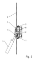
- FIG. 2 shows a side view of an elevator control unit 6 with a button element 7 according to the invention.
- the button mechanism or electronics 8 is shown.
- any (pressure) type of styli can be used.
- the side view can be clearly seen that the originating from the heat source 4 flame 5 is blocked and deflected by the molding 1 and the projection 1 such that it only above the activation display element 2 impinges on the stylus element 7 and there for heating of the Button element 7 provides.
- the heat is dissipated via the thermal connection 3, in this example, the push-button element 7 with the elevator control unit 6 via a thermally conductive joint, with the elevator control unit 6 to the elevator control unit 6.
- a direct action of the flame 5 is not possible by the inventive shape 1, since even with a change in the angle to the stylus element 7, the flame 5 in this example always upwards, ie contrary to the gravitational force, escapes, that draws another angle to the stylus element 7 only the risk of burns for the vandal after, but no direct action on the activation display element 2 is possible.
- FIG. 3A shows an example of an inventive button element 7 with the activation display element 2 and the molding 1, here a projection.
- the molding 1 has in this example an arcuate lower edge 9 and protrudes out of the key plane 11, wherein the transition between the flat key element 11 and the molding 1 is flowing. This shape of the molding 1 creates a groove 10 over the entire length of the key element 7. In or near this channel 10, the activation display element 2 is arranged.
- the key element 7 in this example has a length of about 4.7 cm and a width on the sides of the button element 7 of about 3 cm. The maximum width is about 3.3 cm due to the arched lower edge.
- the molding 1 has relative to the activation indicator 2, a relative height of a maximum of about 0.3 cm.
- Figure 3B-F show further examples of possible inventive button elements 7 with the activation display element 2 and the molding 1 in different embodiments.
- the general shape of the key element 7 is arbitrary. So of course, a round button element 7 is conceivable.
- the activation indicator 2 could be located in a depression or trough.
- the entire key element 7 could also be concave.
- the molding 1 need not be configured over the entire length of the stylus element 7 as a fire barrier. The molding 1 need only be shaped so that a direct action on the activation display element 2 is avoided.
Landscapes
- Elevator Control (AREA)
Description
- Die Erfindung betrifft eine Aufzugsbedieneinheit mit einem Tasterelement, wobei das Tasterelement ein Aktivierungsanzeigeelement aufweist.
- Gerade in öffentlichen Gebäuden, jedoch nicht nur, ist die Gefahr gross, dass Aufzugsanlagen und deren Komponenten durch mutwillige Zerstörung beschädigt werden. Um derartige Gefahren zu reduzieren werden zum Beispiel die Bedieneinheiten einer Aufzugsanlage so gestaltet, dass sie gegen eine mechanische Gewalteinwirkung weitestgehend unempfindlich sind. Dies bedeutet zum Beispiel, dass die Tasterelemente bzw. Druckknopfschalter einer Bedieneinheit aus einem robusten Material, wie etwa Metall gearbeitet und so eingekapselt sind, dass sie mittels eines Werkzeugs nicht ausgehebelt oder beschädigt werden können.
- Die
US-A-4 822 963 beschreibt eine vandalenresistente Druckknopfanordnung mit einem in einem Führungsring verlaufenden Druckknopf. Bedienungsseitig weisen der Druckknopf und der Führungsring eine sphärische Oberfläche auf, die durch eine bedienungsseitige Öffnung in einer die Druckknopfanordnung tragenden Frontplatte begrenzt wird. Der Führungsring ist an der bedienungsseitigen Peripherie so ausgebildet, dass er präzise in die kreisrunde Schulter eingesetzt werden kann, wobei seine sphärische Oberfläche nahtlos in die Oberfläche der Frontplatte übergeht. Der stufenförmige Übergang von einer Führungsringöffnung zur anderen Führungsringöffnung bildet eine kreisrunde Schulter, die die Bewegung des Druckknopfes in Richtung Schalter begrenzt. Das bedienungsseitige Ende des Druckknopfes ist so ausgebildet, dass er in der bedienungsseitigen Öffnung des Führungsringes geführt wird und bis zur kreisrunden Schulter verschiebbar ist, wobei die verjüngte Öffnung als zweite Führungsfläche dient. Eine vom Schalter ausgehende Federkraft presst den Druckknopf an der Stelle der Federklammer gegen den Führungsring, sodass die sphärische Oberfläche des Druckknopfes nahtlos in die sphärische Oberfläche des Führungsringes übergeht. Der Führungsring bildet somit einen Schutz vor mechanischen Einwirkungen. Ein Hebelwerkzeug kann durch diesen Ring nicht an den Druckknopf angesetzt werden und diesen aushebeln. -
EP 0473934 B1 offenbart ein vandalenrestistentes Druckknopfelement, bei dem Führungsringe von einer Montageplatte getragen werden, die in einem Abstand von als Frontplatten dienenden Abdeckungen von Anzeige-Meldeelementen oder modularen Wandelementen von Aufzugskabinen gehalten wird. Die Führungsringe liegen mit einer ersten Schulter auf der Montageplatte auf und werden von in ersten Nuten eingelegten Rückhalteringen mit der Montageplatte verbunden. Die gestanzten Öffnungen der Montageplatte sind so bemessen, dass zwischen dem verjüngten Durchmesser der Führungsringe und der Montageplatte ein Spiel entsteht, dank dem die Führungsringe auf die gestanzten Öffnungen der Frontplatten ausrichtbar sind, wobei die Masse der Rückhalteringe so gewählt ist, dass das Spiel in jedem Falle überdeckt wird. Entlang ersten und zweiten Führungsflächen gleiten in die Führungsringe eingesetzte Druckknöpfe, die mit ihren Enden Schalter bestätigen. Vom Schalter ausgehende Federkräfte pressen den Druckknopf soweit in Gegenbetätigungsrichtung bis eine Federklammer am Ende des Führungsringes ansteht. In dieser Lage bildet eine sphärische Oberfläche des Führungsringes bedienungsseitig eine nahtlose Fläche. Auch hier ist der Schutz massgeblich vom Führungsring abhängig. - Für Benutzer einer Aufzugsanlage ist es wichtig eine Rückmeldung zu erhalten, wenn sie das Tasterelement gedrückt haben, sodass sie verifizieren können, dass die Eingabe des Fahrziels erfolgreich war. Eine derartige Rückmeldung erfolgt meist über ein optisches Signal. Dazu weist das Tasterelement ein transparentes Fenster auf, das meist aus Kunststoff besteht. Bei Betätigung des Tasterelements wird ein optisches Signal von einer unter dem transparenten Fenster liegenden Lichtquelle ausgegeben und für die Benutzer sichtbar. Bei diesem transparenten Fenster besteht jedoch die Gefahr, dass mittels eines Feuers, einer Glut oder Ähnlichem das Fenster beschädigt werden kann und somit das Tasterelement ausgetauscht werden muss. Bei
GB 1380690 - Ein weiteres Beispiel von Aufzugsbedieneinheit mit Metalltasten wird in
US-A-4771139 offenbar. - Die Europäische Norm EN 81-71 definiert Schutzmassnahmen gegen eine mutwillige Zerstörung und legt dazu drei Kategorien fest. In der Kategorie 0 wird von einer seltenen und nur leichten Beschädigung ausgegangen, die an jedem Standort des Aufzugs auftreten kann. Dies trifft auch für Gebäude zu, deren Zugang nur für bestimmte Personen eingeschränkt ist und/oder wenn die Benutzung des Aufzugs unter Überwachung, z. B. mittels Videoüberwachung, steht. Für die Kategorie 0 gibt es in der EN 81-71 keine besonderen Anforderungen, da davon ausgegangen wird, dass bereits ein minimaler Schutz gegen Vandalismus aus der Norm EN 81-1/2 besteht. Bei Aufzügen der Kategorie 1 ist die unbeobachtete allgemeine Öffentlichkeit berücksichtigt, bei der es gelegentlich zu mässigem Vandalismus kommen kann. Für diese Kategorie sind zusätzliche Schutzmassnahmen zu erfüllen. Bei Aufzügen der Kategorie 2 wird vom schweren Vandalismus ausgegangen, weshalb der Aufzug resistent gegen derartige Einwirkungen ausgeführt sein muss und über die Kategorie 1 hinaus gehende Anforderungen erfüllen muss. Die Europäische Norm EN 81-71 spezifiziert im Anhang F Brandprüfungs-Kriterien, damit verifiziert werden kann, ob Aufzugsbedieneinheiten und deren Tasterelemente genügend Schutz vor einer Wärmequelle haben. Damit ein Tasterelement als vandalenrestistent (Kategorie 1 oder 2) gilt, muss es die Einwirkung einer 40 mm Flamme in einer Zeit zwischen 60 und 120 Sekunden überstehen.
- Die Aufgabe der Erfindung besteht darin, dass eine Lösung für ein vandalenrestistentes Tasterelement, das sowohl gegen mechanische als auch thermische Einwirkungen geschützt ist, vorgeschlagen wird.
- Ein Aspekt besteht darin, dass bei einer Aufzugsbedieneinheit mit einem Tasterelement das Tasterelement ein Aktivierungsanzeigenelement aufweist, wobei in einem Bereich, indem ein Abstand zwischen einem Randbereich des Tasterelements und des Aktivierungsanzeigenelements minimal ist, der Randbereich eine Ausformung hat. Dabei ist das Aktivierungsanzeigeelement relativ zu einer Höhe der Ausformung tiefer angeordnet, so dass das Aktivierungsanzeigenelement von der direkten Einwirkung von einer an der Ausformung des Tasterelements einwirkende Wärmequelle geschützt ist.
- Das Tasterelement ist idealerweise aus einem Stück gefertigt und ist in einer Aussparung der Aufzugsbedieneinheit eingebettet, so dass kein Führungsring bzw. Führungsrahmen notwendig ist. Dabei ist das Tasterelement derart eingebettet, dass keine Möglichkeit für den Ansatz eines mechanischen Hebels besteht und somit das Tasterelement vor mechanischen Einwirkungen geschützt ist. Das Tasterelement besteht aus einem Material, welches weitestgehend unempfindlich vor mechanischen und/oder thermischen Einwirkungen ist. Dieses Material kann Metall, Stahl, eine Metalllegierung, Keramik etc. sein.
- Die Ausformung kann in Form einer Auskragung ausgebildet sein. Eine Auskragung kann eine Wulst, ein fliessender Übergang, eine Welle, eine (Halb)-Hyperbel, eine (Halb)-Parabel, eine Hervorhebung, eine Barriere oder Ähnliches sein. Vorstellbar ist auch, dass das Aktivierungsanzeigeelement in einer Mulde, einer Vertiefung, einer Rinne oder Ähnlichem angeordnet ist. Vorzugsweise ist zumindest die Ausformung aus vollem Material, also massiv, gearbeitet bzw. gefertigt, was aufgrund der grösseren Masse an Material zu einer langsameren Erwärmung führt.
- Der Abstand des Aktivierungsanzeigenelements zur Ausformung bestimmt sich im Allgemeinen durch die Höhe der Ausformung relativ zum Aktivierungsanzeigenelement bzw. von der Form der Ausformung.
- Das Aktivierungsanzeigenelement ist transparent oder für Licht durchlässig und kann zum Beispiel aus Kunststoff, Keramik, Polykarbonat etc. ausgestaltet sein.
- Als Wärmequelle wird ein Feuer (z. B. ein Feuerzeug, eine Kerze, ein Bunsenbrenner etc.), eine Glut (z. B. eine Zigarette etc.) etc. verwendet.
- Das Tasterelement ist mit der Aufzugsbedieneinheit thermisch verbunden, d. h. eine auf das Tasterelement einwirkende Wärme kann über eine thermische Verbindung an die Aufzugsbedieneinheit abgeleitet werden. Eine thermische Verbindung besteht dann, wenn sich zwei thermisch leitende Materialien berühren bzw. einen derart geringen Abstand zueinander haben, dass Wärme von einem Material zum anderen Material abgeleitet wird. Die thermische Verbindung kann somit durch die Einbettung des Tasterelements in die Aufzugsbedieneinheit oder auch durch zum Beispiel einem Gelenk, einer Drahtverbindung oder Ähnlichem geschehen. Eine gute thermische Verbindung bildet zum Beispiel eine Metall-Metall-Verbindung zwischen der Aufzugsbedieneinheit und dem Tasterelement.
- Ein Vorteil der Erfindung besteht darin, dass die erfindungsgemässen Tasterelemente trotz ihrer Vandalenresistenz hohen ästhetischen Anforderungen entsprechen können.
- Ein weiterer Vorteil besteht darin, dass nicht mehr unterschieden werden muss zwischen vandalenresistenten und nicht vandalenresistenten Tasterelementen. Es wird nur ein Tasterelement benötigt, das den Anforderungen für jede Art von Gebäuden entspricht und somit sehr kosteneffektiv ist.
- Noch ein weiterer Vorteil besteht darin, dass die Ausformung eine verbesserte Hebelwirkung des Tasterelements bewirkt, da durch die Ausformung ein verlängerter Hebelarm entsteht. Somit kann die Kraft zur Betätigung des Tasterelements deutlich verringert werden.
- Noch ein weiterer Vorteil besteht darin, dass durch die erfindungsgemässe Ausgestaltung kein Führungsring bzw. -rahmen benötigt wird, was zu einer Vereinfachung der Herstellung des Tasterelements und der damit verbundenen Kostenreduktion führt.
- Die Erfindung wird anhand eines in den Figuren dargestellten Ausführungsbeispiels näher erläutert. Dabei zeigen
- Figur 1
- eine Aufzugsbedieneinheit mit einem erfindungsgemässen Tasterelement,
- Figur 2
- eine Seitenansicht einer Aufzugsbedieneinheit mit einem erfindungsgemässen Tasterelement,
- Figur 3A
- ein erfindungsgemässes Tasterelement und
- Figur 3B-F
- alternative erfindungsgemässe Tasterelemente.
-
Fig. 1 zeigt eine Aufzugsbedieneinheit 6 mit einem erfindungsgemässen Tasterelement 7. Die Aufzugsbedieneinheit 6 weist in diesem Beispiel ein Tasterelement 7 auf. Jedoch können auch mehrere Tasterelemente 7 auf der Aufzugsbedieneinheit 6 angeordnet sein. Eine derartige Aufzugsbedieneinheit 6 ist meist vertikal an einer Wand in einem Gebäude oder in einer Aufzugskabine montiert. So können ein oberer Randbereich, der hin zur Decke des Gebäudes bzw. der Aufzugskabine gerichtet ist und ein unterer Randbereich, der hin zum Fussboden bzw. Boden der Aufzugskabine gerichtet ist, definiert werden. In diesem Beispiel bestehen die Aufzugsbedieneinheit 6 und das Tasterelement 7 jeweils aus einem thermisch leitenden Material, wie etwa einem Metall, einer Metalllegierung, Keramik, Kunststoff etc. Das Tasterelement 7 und die Aufzugsbedieneinheit 6 sind thermisch miteinander verbunden, sodass Wärme, die auf das Tasterelement 7 einwirkt über die thermische Verbindung 3 an die Aufzugsbedieneinheit 6 abgeleitet wird. Dadurch wird das Risiko einer Überhitzung des Tasterelements 7 reduziert. - Das Tasterelement 7 weist weiter eine Auskragung 1 am unteren Randbereich und ein Aktivierungsanzeigeelement 2 auf. Das Aktivierungsanzeigeelement 2 besteht aus einem lichtdurchlässigen Material, zum Beispiel Kunststoff, Keramik, Polykarbonat etc. und ist mit einem Abstand zur Auskragung 1 angeordnet. Grundsätzlich hängt der Abstand des Aktivierungsanzeigeelement 2 zur Ausformung 1, bzw. in diesem Beispiel zur Auskragung 1, von der Höhe des Randbereichs relativ zur Lage bzw. Höhe des Aktivierungsanzeigeelements 2 oder von der Form der Ausformung 1 ab, wobei das Aktivierungsanzeigeelement 2 stets relativ zur Höhe der Auskragung 1 tiefer angeordnet ist. Je höher zum Beispiel die Auskragung 1 ist bzw. aus der Ebene herausragt desto grösser kann der Abstand des Aktivierungsanzeigeelements 2 zur Auskragung 1 gewählt werden. Aber auch die Form der Ausformung kann so gewählt werden, dass eine Flamme 5 vom Aktivierungsanzeigeelement 2 weggeleitet bzw. vorbeigeleitet bzw. darüber hinweg geleitet wird. Im vorliegenden Beispiel ist das Aktivierungsanzeigeelement 2 im Übergang von der Ebene des Tasterelements 7 (oberer Teil des Tasterelements) zur Auskragung 1, also in einer so entstehenden Rinne angeordnet.
- Die Auskragung 1 oder allgemein die Ausformung 1 wirkt erfindungsgemäss als Hitzeschild bzw. als Feuerbarriere und/oder als Strömungsumlenkeinrichtung, sodass das Aktivierungsanzeigeelement 2 von der direkten Einwirkung von einer von unten an die Auskragung 1 des Tasterelements 7 einwirkende Wärmequelle 4 und ihrer Flamme 5 geschützt ist. Ausserdem ist die Auskragung 1 vorzugsweise aus massivem Material gefertigt, sodass für die Erwärmung eine längere Zeitspanne benötigt wird. Wie in
Fig. 1 zu sehen ist, wird die Flamme aufgrund der Geometrie der Auskragung 1 über das Aktivierungsanzeigeelement 2 hinweg geleitet und trifft erst oberhalb des Aktivierungsanzeigeelements 2 auf das Tasterelement 7 auf. Die Flamme 5 kann somit nicht direkt auf das Aktivierungsanzeigeelement 2 einwirken. Die daraus resultierende Erwärmung des Tasterelements 7 wird durch die thermische Verbindung 3 mit der Aufzugsbedieneinheit 6 an die Aufzugsbedieneinheit 6 abgeleitet. Dadurch kann das relativ empfindliche Aktivierungsanzeigeelement 2 von der Flamme 5 bzw. von der Hitzeeinwirkung effektiv geschützt werden und somit ist eine Beschädigung nur mit hohem Aufwand möglich. -
Figur 2 zeigt eine Seitenansicht einer Aufzugsbedieneinheit 6 mit einem erfindungsgemässen Tasterelement 7. In diesem Beispiel ist die Tastermechanik bzw. - elektronik 8 dargestellt. Für das erfindungsgemässe Tasterelement 7 können beliebige (Druck-)Tastertypen verwendet werden. Durch die Seitenansicht ist gut zu sehen, dass die von der Wärmequelle 4 stammende Flamme 5 durch die Ausformung 1 bzw. der Auskragung 1 derart blockiert und abgelenkt wird, dass sie erst oberhalb des Aktivierungsanzeigeelements 2 auf das Tasterelement 7 auftrifft und dort für eine Erwärmung des Tasterelements 7 sorgt. Die Wärme wird über die thermische Verbindung 3, in diesem Beispiel ist das Tasterelement 7 mit der Aufzugsbedieneinheit 6 über ein thermisch leitendes Gelenk verbunden, mit der Aufzugsbedieneinheit 6 an die Aufzugsbedieneinheit 6 abgeführt. Eine direkte Einwirkung der Flamme 5 ist durch die erfindungsgemässe Ausformung 1 nicht möglich, da selbst bei einer Änderung des Winkels zum Tasterelement 7 die Flamme 5 in diesem Beispiel immer nach oben, also entgegen der Gravitationskraft, entweicht, d. h. ein anderer Winkel zum Tasterelement 7 zieht lediglich die Verbrennungsgefahr für den Vandalen nach, jedoch ist keine direkte Einwirkung auf das Aktivierungsanzeigeelement 2 möglich. -
Figur 3A zeigt ein Beispiel für ein erfindungsgemässes Tasterelement 7 mit dem Aktivierungsanzeigeelement 2 und der Ausformung 1, hier eine Auskragung. Die Ausformung 1 weist in diesem Beispiel eine bogenförmige untere Kante 9 auf und ragt aus der Tastenebene 11 heraus, wobei der Übergang zwischen dem ebenen Tastenelement 11 und der Ausformung 1 fliessend ist. Durch diese Form der Ausformung 1 entsteht eine Rinne 10 über die gesamte Länge des Tastenelements 7. In bzw. nahe an dieser Rinne 10 ist das Aktivierungsanzeigeelement 2 angeordnet. Das Tastenelement 7 hat in diesem Beispiel eine Länge von ca. 4,7 cm und eine Breite an den Seiten des Tasterelements 7 von ca. 3 cm. Die maximale Breite beträgt aufgrund der bogenförmigen unteren Kante ca. 3,3 cm. Die Ausformung 1 hat gegenüber dem Aktivierungsanzeigeelement 2 eine relative Höhe von maximal ca. 0,3 cm. -
Figur 3B-F zeigen weitere Beispiele möglicher erfindungsgemässer Tasterelemente 7 mit dem Aktivierungsanzeigeelement 2 und der Ausformung 1 in unterschiedlichen Ausgestaltungsformen. Die allgemeine Form des Tastenelements 7 ist beliebig. So ist selbstverständlich auch ein rundes Tasterelement 7 vorstellbar. Auch könnte sich die Aktivierungsanzeige 2 in einer Vertiefung bzw. Mulde befinden. Das gesamte Tastenelement 7 könnte auch konkav geformt sein. Auch muss die Ausformung 1 nicht über die gesamte Länge des Tasterelements 7 als Feuerbarriere ausgestaltet sein. Die Ausformung 1 muss nur so geformt sein, dass eine direkte Einwirkung auf das Aktivierungsanzeigeelement 2 vermieden wird.
Claims (13)
- Aufzugsbedieneinheit (6), welche vertikal an einer Wand in einem Gebäude oder in einer Aufzugskabine montiert ist, mit einem einen oberen und einen unteren Randbereich aufweisenden Tasterelement (7), wobei das Tasterelement (7) ein Aktivierungsanzeigeelement (2) aufweist,
dadurch gekennzeichnet,
dass in einem Bereich, in dem ein Abstand zwischen dem unteren Randbereich des Tasterelements (7) und dem Aktivierungsanzeigeelement (2) minimal ist, der untere Randbereich eine Ausformung (1) aufweist und
dass das Aktivierungsanzeigeelement (2) relativ zu einer Höhe der Ausformung (1) tiefer angeordnet ist, so dass das Aktivierungsanzeigeelement (2) aufgrund der tieferen Anordnung relativ zu einer Höhe der Ausformung (1) von einer unten an der Ausformung (1) des Tasterelements (7) einwirkenden Flamme (5) einer Wärmequelle (4) geschützt ist. - Aufzugsbedieneinheit nach Anspruch 1,
dadurch gekennzeichnet,
dass die Ausformung (1) in Form einer Auskragung, einer Wulst, einer Hervorhebung, einer Welle oder einer Barriere ausgebildet ist. - Aufzugsbedieneinheit nach den Ansprüchen 1 oder 2,
dadurch gekennzeichnet,
dass die Wärme der einwirkenden Wärmequelle (4) durch eine Form der Ausformung (1) von dem Aktivierungsanzeigeelement (2) weggeleitet wird. - Aufzugsbedieneinheit (6) nach Anspruch 1,
dadurch gekennzeichnet,
dass die Aktivierungsanzeige (2) in einer Mulde, einer Rinne oder einer Vertiefung angeordnet ist. - Aufzugsbedieneinheit (6) nach einem der vorangegangenen Ansprüche,
dadurch gekennzeichnet,
dass der Abstand des Aktivierungsanzeigeelements (2) zur Ausformung (1) abhängig von der Höhe des Randbereichs relativ zum Aktivierungsanzeigeelement (2) ist. - Aufzugsbedieneinheit (6) nach einem der vorangegangenen Ansprüche,
dadurch gekennzeichnet,
dass der Abstand des Aktivierungsanzeigeelements (2) abhängig von der Form der Ausformung (1) ist. - Aufzugsbedieneinheit (6) nach einem der vorangegangenen Ansprüche,
dadurch gekennzeichnet,
dass die Ausformung (1) ein Hitzeschild, eine Feuerbarriere und/oder eine Strömungsumlenkeinrichtung ist. - Aufzugsbedieneinheit (6) nach einem der vorangegangenen Ansprüche,
dadurch gekennzeichnet,
dass zumindest die Ausformung aus vollem Material gefertigt ist. - Aufzugsbedieneinheit (6) nach einem der vorangegangenen Ansprüche,
dadurch gekennzeichnet,
dass das Tasterelement (7) aus einem nicht-brennbaren Material besteht. - Aufzugsbedieneinheit (6) nach einem der vorangegangenen Ansprüche,
dadurch gekennzeichnet,
dass das Aktivierungsanzeigeelement (2) aus Kunststoff oder Keramik besteht. - Aufzugsbedieneinheit (6) nach einem der vorangegangenen Ansprüche,
dadurch gekennzeichnet,
dass das Aktivierungsanzeigeelement (2) transparent oder lichtdurchlässig ist. - Aufzugsbedieneinheit (6) nach einem der vorangegangen Ansprüche,
dadurch gekennzeichnet,
dass das Tasterelement (7) eine thermische Verbindung (3) mit der Aufzugsbedieneinheit (6) aufweist. - Aufzugsbedieneinheit (6) nach Anspruch 10,
dadurch gekennzeichnet,
dass die thermische Verbindung (3) eine Metall-Metall-Verbindung ist.
Priority Applications (1)
| Application Number | Priority Date | Filing Date | Title |
|---|---|---|---|
| EP10735295.7A EP2460166B1 (de) | 2009-07-27 | 2010-07-27 | Aufzugsbedieneinheit mit einem tasterelement |
Applications Claiming Priority (3)
| Application Number | Priority Date | Filing Date | Title |
|---|---|---|---|
| EP09166496 | 2009-07-27 | ||
| EP10735295.7A EP2460166B1 (de) | 2009-07-27 | 2010-07-27 | Aufzugsbedieneinheit mit einem tasterelement |
| PCT/EP2010/060874 WO2011012613A1 (de) | 2009-07-27 | 2010-07-27 | Aufzugsbedieneinheit mit einem tasterelement |
Publications (2)
| Publication Number | Publication Date |
|---|---|
| EP2460166A1 EP2460166A1 (de) | 2012-06-06 |
| EP2460166B1 true EP2460166B1 (de) | 2015-11-04 |
Family
ID=41334565
Family Applications (1)
| Application Number | Title | Priority Date | Filing Date |
|---|---|---|---|
| EP10735295.7A Not-in-force EP2460166B1 (de) | 2009-07-27 | 2010-07-27 | Aufzugsbedieneinheit mit einem tasterelement |
Country Status (2)
| Country | Link |
|---|---|
| EP (1) | EP2460166B1 (de) |
| WO (1) | WO2011012613A1 (de) |
Family Cites Families (6)
| Publication number | Priority date | Publication date | Assignee | Title |
|---|---|---|---|---|
| GB1380690A (en) | 1971-06-04 | 1975-01-15 | Bennie Lifts Ltd | Illuminated push-button assemblies and mountings therefor |
| US4822963A (en) | 1985-07-10 | 1989-04-18 | Adams Elevator Equipment Co. | Vandal resistant push button assembly |
| US4771139A (en) * | 1986-06-27 | 1988-09-13 | Desmet Gregory L | Keyboard with metal cover and improved switches |
| FR2692715B1 (fr) * | 1989-06-06 | 1994-10-21 | Long Lite | Dispositif de protection pour interrupteurs électriques. |
| US5201409A (en) | 1990-09-04 | 1993-04-13 | Inventio Ag | Vandal resistant push button assembly |
| ATE168825T1 (de) * | 1994-10-05 | 1998-08-15 | Inventio Ag | Dem benutzer zugeneigtes tableau für aufzüge |
-
2010
- 2010-07-27 EP EP10735295.7A patent/EP2460166B1/de not_active Not-in-force
- 2010-07-27 WO PCT/EP2010/060874 patent/WO2011012613A1/de not_active Ceased
Also Published As
| Publication number | Publication date |
|---|---|
| WO2011012613A1 (de) | 2011-02-03 |
| EP2460166A1 (de) | 2012-06-06 |
Similar Documents
| Publication | Publication Date | Title |
|---|---|---|
| DE102008014443B4 (de) | Beleuchteter Taster mit Vergussmasse | |
| DE102007025433B4 (de) | Folienschaltermodul | |
| DE3045962A1 (de) | Tastatur mit beleuchteten tasten | |
| EP0123184A2 (de) | Tastaturanordnung | |
| DE10228141A1 (de) | Gargerät | |
| EP2853027A1 (de) | Sensorelementeinrichtung für einen kapazitiven berührungsschalter einer bedieneinrichtung, bedieneinrichtung und kochfeld | |
| DE19527826A1 (de) | Strahlungs-Kochstelleneinheit | |
| EP0473934B1 (de) | Vandalenresistentes Druckknopfelement | |
| EP2460166A1 (de) | Aufzugsbedieneinheit mit einem tasterelement | |
| DE102013003659B4 (de) | Beleuchteter kapazitiver Taster | |
| DE102010055395A1 (de) | Schlüsselkarterschalter | |
| EP3884554B1 (de) | Elektrisches installationsgerät | |
| EP2478541B1 (de) | Betätiger mit signalanzeige | |
| DE102016100795B4 (de) | Wippschalter mit beweglichen Lichtschächten | |
| EP0592925A1 (de) | Handgefahrenmelder | |
| EP0884265B1 (de) | Anzeigevorrichtung für Aufzüge | |
| EP1245033B1 (de) | Türöffnerschalter | |
| EP0660800B1 (de) | Sicherheitseinrichtung an der einlaufstelle eines umlaufenden handlaufs einer rolltreppe, eines rollsteiges oder dgl. | |
| EP1653621B1 (de) | Optischer Berührschalter | |
| EP1873596B1 (de) | Tragbarer Funkfernsteuerungssender mit beleuchteten Tasten | |
| DE102014215840A1 (de) | Bedienelementteil für eine Bedieneinrichtung, Bedieneinrichtung sowie Elektrogerät mit einer Bedieneinrichtung | |
| DE9113754U1 (de) | Elektrischer Kurzhub-Drucktaster | |
| DE102021105646A1 (de) | Bedienvorrichtung für ein Fahrzeug | |
| DE3728166C2 (de) | ||
| DE202007007116U1 (de) | Beleuchtete Tastatur |
Legal Events
| Date | Code | Title | Description |
|---|---|---|---|
| PUAI | Public reference made under article 153(3) epc to a published international application that has entered the european phase |
Free format text: ORIGINAL CODE: 0009012 |
|
| 17P | Request for examination filed |
Effective date: 20120113 |
|
| AK | Designated contracting states |
Kind code of ref document: A1 Designated state(s): AL AT BE BG CH CY CZ DE DK EE ES FI FR GB GR HR HU IE IS IT LI LT LU LV MC MK MT NL NO PL PT RO SE SI SK SM TR |
|
| DAX | Request for extension of the european patent (deleted) | ||
| GRAP | Despatch of communication of intention to grant a patent |
Free format text: ORIGINAL CODE: EPIDOSNIGR1 |
|
| INTG | Intention to grant announced |
Effective date: 20150715 |
|
| GRAS | Grant fee paid |
Free format text: ORIGINAL CODE: EPIDOSNIGR3 |
|
| GRAA | (expected) grant |
Free format text: ORIGINAL CODE: 0009210 |
|
| AK | Designated contracting states |
Kind code of ref document: B1 Designated state(s): AL AT BE BG CH CY CZ DE DK EE ES FI FR GB GR HR HU IE IS IT LI LT LU LV MC MK MT NL NO PL PT RO SE SI SK SM TR |
|
| REG | Reference to a national code |
Ref country code: GB Ref legal event code: FG4D Free format text: NOT ENGLISH |
|
| REG | Reference to a national code |
Ref country code: CH Ref legal event code: EP |
|
| REG | Reference to a national code |
Ref country code: AT Ref legal event code: REF Ref document number: 759706 Country of ref document: AT Kind code of ref document: T Effective date: 20151115 |
|
| REG | Reference to a national code |
Ref country code: IE Ref legal event code: FG4D Free format text: LANGUAGE OF EP DOCUMENT: GERMAN |
|
| REG | Reference to a national code |
Ref country code: DE Ref legal event code: R096 Ref document number: 502010010589 Country of ref document: DE |
|
| REG | Reference to a national code |
Ref country code: NL Ref legal event code: MP Effective date: 20151104 |
|
| REG | Reference to a national code |
Ref country code: LT Ref legal event code: MG4D |
|
| PG25 | Lapsed in a contracting state [announced via postgrant information from national office to epo] |
Ref country code: NL Free format text: LAPSE BECAUSE OF FAILURE TO SUBMIT A TRANSLATION OF THE DESCRIPTION OR TO PAY THE FEE WITHIN THE PRESCRIBED TIME-LIMIT Effective date: 20151104 Ref country code: IT Free format text: LAPSE BECAUSE OF FAILURE TO SUBMIT A TRANSLATION OF THE DESCRIPTION OR TO PAY THE FEE WITHIN THE PRESCRIBED TIME-LIMIT Effective date: 20151104 Ref country code: IS Free format text: LAPSE BECAUSE OF FAILURE TO SUBMIT A TRANSLATION OF THE DESCRIPTION OR TO PAY THE FEE WITHIN THE PRESCRIBED TIME-LIMIT Effective date: 20160304 Ref country code: LT Free format text: LAPSE BECAUSE OF FAILURE TO SUBMIT A TRANSLATION OF THE DESCRIPTION OR TO PAY THE FEE WITHIN THE PRESCRIBED TIME-LIMIT Effective date: 20151104 Ref country code: NO Free format text: LAPSE BECAUSE OF FAILURE TO SUBMIT A TRANSLATION OF THE DESCRIPTION OR TO PAY THE FEE WITHIN THE PRESCRIBED TIME-LIMIT Effective date: 20160204 Ref country code: HR Free format text: LAPSE BECAUSE OF FAILURE TO SUBMIT A TRANSLATION OF THE DESCRIPTION OR TO PAY THE FEE WITHIN THE PRESCRIBED TIME-LIMIT Effective date: 20151104 Ref country code: ES Free format text: LAPSE BECAUSE OF FAILURE TO SUBMIT A TRANSLATION OF THE DESCRIPTION OR TO PAY THE FEE WITHIN THE PRESCRIBED TIME-LIMIT Effective date: 20151104 |
|
| PG25 | Lapsed in a contracting state [announced via postgrant information from national office to epo] |
Ref country code: FI Free format text: LAPSE BECAUSE OF FAILURE TO SUBMIT A TRANSLATION OF THE DESCRIPTION OR TO PAY THE FEE WITHIN THE PRESCRIBED TIME-LIMIT Effective date: 20151104 Ref country code: PT Free format text: LAPSE BECAUSE OF FAILURE TO SUBMIT A TRANSLATION OF THE DESCRIPTION OR TO PAY THE FEE WITHIN THE PRESCRIBED TIME-LIMIT Effective date: 20160304 Ref country code: PL Free format text: LAPSE BECAUSE OF FAILURE TO SUBMIT A TRANSLATION OF THE DESCRIPTION OR TO PAY THE FEE WITHIN THE PRESCRIBED TIME-LIMIT Effective date: 20151104 Ref country code: SE Free format text: LAPSE BECAUSE OF FAILURE TO SUBMIT A TRANSLATION OF THE DESCRIPTION OR TO PAY THE FEE WITHIN THE PRESCRIBED TIME-LIMIT Effective date: 20151104 Ref country code: LV Free format text: LAPSE BECAUSE OF FAILURE TO SUBMIT A TRANSLATION OF THE DESCRIPTION OR TO PAY THE FEE WITHIN THE PRESCRIBED TIME-LIMIT Effective date: 20151104 Ref country code: GR Free format text: LAPSE BECAUSE OF FAILURE TO SUBMIT A TRANSLATION OF THE DESCRIPTION OR TO PAY THE FEE WITHIN THE PRESCRIBED TIME-LIMIT Effective date: 20160205 |
|
| PG25 | Lapsed in a contracting state [announced via postgrant information from national office to epo] |
Ref country code: CZ Free format text: LAPSE BECAUSE OF FAILURE TO SUBMIT A TRANSLATION OF THE DESCRIPTION OR TO PAY THE FEE WITHIN THE PRESCRIBED TIME-LIMIT Effective date: 20151104 |
|
| REG | Reference to a national code |
Ref country code: DE Ref legal event code: R097 Ref document number: 502010010589 Country of ref document: DE |
|
| PG25 | Lapsed in a contracting state [announced via postgrant information from national office to epo] |
Ref country code: SK Free format text: LAPSE BECAUSE OF FAILURE TO SUBMIT A TRANSLATION OF THE DESCRIPTION OR TO PAY THE FEE WITHIN THE PRESCRIBED TIME-LIMIT Effective date: 20151104 Ref country code: SM Free format text: LAPSE BECAUSE OF FAILURE TO SUBMIT A TRANSLATION OF THE DESCRIPTION OR TO PAY THE FEE WITHIN THE PRESCRIBED TIME-LIMIT Effective date: 20151104 Ref country code: EE Free format text: LAPSE BECAUSE OF FAILURE TO SUBMIT A TRANSLATION OF THE DESCRIPTION OR TO PAY THE FEE WITHIN THE PRESCRIBED TIME-LIMIT Effective date: 20151104 Ref country code: DK Free format text: LAPSE BECAUSE OF FAILURE TO SUBMIT A TRANSLATION OF THE DESCRIPTION OR TO PAY THE FEE WITHIN THE PRESCRIBED TIME-LIMIT Effective date: 20151104 Ref country code: RO Free format text: LAPSE BECAUSE OF FAILURE TO SUBMIT A TRANSLATION OF THE DESCRIPTION OR TO PAY THE FEE WITHIN THE PRESCRIBED TIME-LIMIT Effective date: 20151104 |
|
| PLBE | No opposition filed within time limit |
Free format text: ORIGINAL CODE: 0009261 |
|
| STAA | Information on the status of an ep patent application or granted ep patent |
Free format text: STATUS: NO OPPOSITION FILED WITHIN TIME LIMIT |
|
| 26N | No opposition filed |
Effective date: 20160805 |
|
| PGFP | Annual fee paid to national office [announced via postgrant information from national office to epo] |
Ref country code: CH Payment date: 20160713 Year of fee payment: 7 Ref country code: DE Payment date: 20160722 Year of fee payment: 7 |
|
| PG25 | Lapsed in a contracting state [announced via postgrant information from national office to epo] |
Ref country code: SI Free format text: LAPSE BECAUSE OF FAILURE TO SUBMIT A TRANSLATION OF THE DESCRIPTION OR TO PAY THE FEE WITHIN THE PRESCRIBED TIME-LIMIT Effective date: 20151104 |
|
| PG25 | Lapsed in a contracting state [announced via postgrant information from national office to epo] |
Ref country code: BE Free format text: LAPSE BECAUSE OF NON-PAYMENT OF DUE FEES Effective date: 20160731 |
|
| GBPC | Gb: european patent ceased through non-payment of renewal fee |
Effective date: 20160727 |
|
| PG25 | Lapsed in a contracting state [announced via postgrant information from national office to epo] |
Ref country code: MC Free format text: LAPSE BECAUSE OF FAILURE TO SUBMIT A TRANSLATION OF THE DESCRIPTION OR TO PAY THE FEE WITHIN THE PRESCRIBED TIME-LIMIT Effective date: 20151104 |
|
| PG25 | Lapsed in a contracting state [announced via postgrant information from national office to epo] |
Ref country code: FR Free format text: LAPSE BECAUSE OF NON-PAYMENT OF DUE FEES Effective date: 20160801 |
|
| REG | Reference to a national code |
Ref country code: FR Ref legal event code: ST Effective date: 20170331 |
|
| REG | Reference to a national code |
Ref country code: IE Ref legal event code: MM4A |
|
| PG25 | Lapsed in a contracting state [announced via postgrant information from national office to epo] |
Ref country code: GB Free format text: LAPSE BECAUSE OF NON-PAYMENT OF DUE FEES Effective date: 20160727 |
|
| PG25 | Lapsed in a contracting state [announced via postgrant information from national office to epo] |
Ref country code: IE Free format text: LAPSE BECAUSE OF NON-PAYMENT OF DUE FEES Effective date: 20160727 |
|
| PG25 | Lapsed in a contracting state [announced via postgrant information from national office to epo] |
Ref country code: LU Free format text: LAPSE BECAUSE OF NON-PAYMENT OF DUE FEES Effective date: 20160727 |
|
| REG | Reference to a national code |
Ref country code: AT Ref legal event code: MM01 Ref document number: 759706 Country of ref document: AT Kind code of ref document: T Effective date: 20160727 |
|
| PG25 | Lapsed in a contracting state [announced via postgrant information from national office to epo] |
Ref country code: AT Free format text: LAPSE BECAUSE OF NON-PAYMENT OF DUE FEES Effective date: 20160727 |
|
| REG | Reference to a national code |
Ref country code: DE Ref legal event code: R119 Ref document number: 502010010589 Country of ref document: DE |
|
| REG | Reference to a national code |
Ref country code: CH Ref legal event code: PL |
|
| PG25 | Lapsed in a contracting state [announced via postgrant information from national office to epo] |
Ref country code: LI Free format text: LAPSE BECAUSE OF NON-PAYMENT OF DUE FEES Effective date: 20170731 Ref country code: CH Free format text: LAPSE BECAUSE OF NON-PAYMENT OF DUE FEES Effective date: 20170731 Ref country code: DE Free format text: LAPSE BECAUSE OF NON-PAYMENT OF DUE FEES Effective date: 20180201 |
|
| PG25 | Lapsed in a contracting state [announced via postgrant information from national office to epo] |
Ref country code: HU Free format text: LAPSE BECAUSE OF FAILURE TO SUBMIT A TRANSLATION OF THE DESCRIPTION OR TO PAY THE FEE WITHIN THE PRESCRIBED TIME-LIMIT; INVALID AB INITIO Effective date: 20100727 Ref country code: CY Free format text: LAPSE BECAUSE OF FAILURE TO SUBMIT A TRANSLATION OF THE DESCRIPTION OR TO PAY THE FEE WITHIN THE PRESCRIBED TIME-LIMIT Effective date: 20151104 |
|
| PG25 | Lapsed in a contracting state [announced via postgrant information from national office to epo] |
Ref country code: MK Free format text: LAPSE BECAUSE OF FAILURE TO SUBMIT A TRANSLATION OF THE DESCRIPTION OR TO PAY THE FEE WITHIN THE PRESCRIBED TIME-LIMIT Effective date: 20151104 Ref country code: TR Free format text: LAPSE BECAUSE OF FAILURE TO SUBMIT A TRANSLATION OF THE DESCRIPTION OR TO PAY THE FEE WITHIN THE PRESCRIBED TIME-LIMIT Effective date: 20151104 Ref country code: MT Free format text: LAPSE BECAUSE OF FAILURE TO SUBMIT A TRANSLATION OF THE DESCRIPTION OR TO PAY THE FEE WITHIN THE PRESCRIBED TIME-LIMIT Effective date: 20151104 |
|
| PG25 | Lapsed in a contracting state [announced via postgrant information from national office to epo] |
Ref country code: BG Free format text: LAPSE BECAUSE OF FAILURE TO SUBMIT A TRANSLATION OF THE DESCRIPTION OR TO PAY THE FEE WITHIN THE PRESCRIBED TIME-LIMIT Effective date: 20151104 |
|
| PG25 | Lapsed in a contracting state [announced via postgrant information from national office to epo] |
Ref country code: AL Free format text: LAPSE BECAUSE OF FAILURE TO SUBMIT A TRANSLATION OF THE DESCRIPTION OR TO PAY THE FEE WITHIN THE PRESCRIBED TIME-LIMIT Effective date: 20151104 |