EP2458345A1 - Dosiervorrichtung - Google Patents
Dosiervorrichtung Download PDFInfo
- Publication number
- EP2458345A1 EP2458345A1 EP10192661A EP10192661A EP2458345A1 EP 2458345 A1 EP2458345 A1 EP 2458345A1 EP 10192661 A EP10192661 A EP 10192661A EP 10192661 A EP10192661 A EP 10192661A EP 2458345 A1 EP2458345 A1 EP 2458345A1
- Authority
- EP
- European Patent Office
- Prior art keywords
- outlet opening
- dosing
- dosing unit
- movement
- receiving device
- Prior art date
- Legal status (The legal status is an assumption and is not a legal conclusion. Google has not performed a legal analysis and makes no representation as to the accuracy of the status listed.)
- Granted
Links
- 238000005520 cutting process Methods 0.000 claims description 8
- 230000007246 mechanism Effects 0.000 claims description 4
- 239000000463 material Substances 0.000 description 18
- 239000000126 substance Substances 0.000 description 7
- 239000000843 powder Substances 0.000 description 4
- 238000000926 separation method Methods 0.000 description 4
- 238000000605 extraction Methods 0.000 description 3
- 238000000034 method Methods 0.000 description 3
- 239000002245 particle Substances 0.000 description 3
- 230000008569 process Effects 0.000 description 3
- 230000008878 coupling Effects 0.000 description 2
- 238000010168 coupling process Methods 0.000 description 2
- 238000005859 coupling reaction Methods 0.000 description 2
- 238000006073 displacement reaction Methods 0.000 description 2
- 238000002474 experimental method Methods 0.000 description 2
- 230000009969 flowable effect Effects 0.000 description 2
- 230000035939 shock Effects 0.000 description 2
- 230000007704 transition Effects 0.000 description 2
- 241000251468 Actinopterygii Species 0.000 description 1
- 241000408529 Libra Species 0.000 description 1
- 238000010521 absorption reaction Methods 0.000 description 1
- 230000008901 benefit Effects 0.000 description 1
- 239000004568 cement Substances 0.000 description 1
- 210000000078 claw Anatomy 0.000 description 1
- 230000001112 coagulating effect Effects 0.000 description 1
- 238000000576 coating method Methods 0.000 description 1
- 238000010276 construction Methods 0.000 description 1
- 239000007822 coupling agent Substances 0.000 description 1
- 239000000835 fiber Substances 0.000 description 1
- 239000012530 fluid Substances 0.000 description 1
- 230000005484 gravity Effects 0.000 description 1
- 230000004941 influx Effects 0.000 description 1
- 239000007788 liquid Substances 0.000 description 1
- 210000000056 organ Anatomy 0.000 description 1
- 239000006072 paste Substances 0.000 description 1
- 238000003825 pressing Methods 0.000 description 1
- 238000007789 sealing Methods 0.000 description 1
- 239000013049 sediment Substances 0.000 description 1
- 238000007493 shaping process Methods 0.000 description 1
- 239000002689 soil Substances 0.000 description 1
- 238000003860 storage Methods 0.000 description 1
- 238000005303 weighing Methods 0.000 description 1
Images



Classifications
-
- G—PHYSICS
- G01—MEASURING; TESTING
- G01F—MEASURING VOLUME, VOLUME FLOW, MASS FLOW OR LIQUID LEVEL; METERING BY VOLUME
- G01F13/00—Apparatus for measuring by volume and delivering fluids or fluent solid materials, not provided for in the preceding groups
- G01F13/001—Apparatus for measuring by volume and delivering fluids or fluent solid materials, not provided for in the preceding groups for fluent solid material
-
- B—PERFORMING OPERATIONS; TRANSPORTING
- B65—CONVEYING; PACKING; STORING; HANDLING THIN OR FILAMENTARY MATERIAL
- B65B—MACHINES, APPARATUS OR DEVICES FOR, OR METHODS OF, PACKAGING ARTICLES OR MATERIALS; UNPACKING
- B65B1/00—Packaging fluent solid material, e.g. powders, granular or loose fibrous material, loose masses of small articles, in individual containers or receptacles, e.g. bags, sacks, boxes, cartons, cans, or jars
- B65B1/04—Methods of, or means for, filling the material into the containers or receptacles
- B65B1/06—Methods of, or means for, filling the material into the containers or receptacles by gravity flow
-
- B—PERFORMING OPERATIONS; TRANSPORTING
- B65—CONVEYING; PACKING; STORING; HANDLING THIN OR FILAMENTARY MATERIAL
- B65B—MACHINES, APPARATUS OR DEVICES FOR, OR METHODS OF, PACKAGING ARTICLES OR MATERIALS; UNPACKING
- B65B1/00—Packaging fluent solid material, e.g. powders, granular or loose fibrous material, loose masses of small articles, in individual containers or receptacles, e.g. bags, sacks, boxes, cartons, cans, or jars
- B65B1/04—Methods of, or means for, filling the material into the containers or receptacles
- B65B1/08—Methods of, or means for, filling the material into the containers or receptacles by vibratory feeders
-
- G—PHYSICS
- G01—MEASURING; TESTING
- G01G—WEIGHING
- G01G13/00—Weighing apparatus with automatic feed or discharge for weighing-out batches of material
- G01G13/02—Means for automatically loading weigh pans or other receptacles, e.g. disposable containers, under control of the weighing mechanism
-
- G—PHYSICS
- G01—MEASURING; TESTING
- G01G—WEIGHING
- G01G17/00—Apparatus for or methods of weighing material of special form or property
- G01G17/04—Apparatus for or methods of weighing material of special form or property for weighing fluids, e.g. gases, pastes
- G01G17/06—Apparatus for or methods of weighing material of special form or property for weighing fluids, e.g. gases, pastes having means for controlling the supply or discharge
Definitions
- the invention relates to a dosing device with a receiving device which is movably mounted in a predetermined direction of movement and a dosing unit adapted to this dosing device, which can be inserted into the receiving device.
- Flowable substance dosing devices such as powders, pastes or liquids are used in many areas of industry.
- these metering devices have a drive device, a controller and a measuring device for detecting the metered-out mass.
- the supply of flowable substances or the Dosiergut can be done either by a supply line or by a replaceable dosing. So that the dosing unit can be inserted into the dosing device, it must have a receiving device.
- a dosing unit essentially has a removal vessel which contains the dosing material and which is closed by a dosing head.
- the dosing head includes an outlet opening and a closure element, by means of which the outlet opening is variably closable.
- the dosing head can also be provided with a supply device, for example with a supply hose.
- a metering device with a receiving device for a metering unit of the aforementioned type is in the EP 1 959 244 A1 disclosed.
- This has a receiving device for a dosing unit, which is pivotally mounted about a horizontal axis. Oscillating pivoting movements of the receiving device can be produced by means of a striking mechanism, wherein powdered dosing material in the dosing unit is loosened up by the pivoting movements.
- powder bridges are torn by the pivoting movements, which inhibit the influx of dosing to the outlet opening. In powder bridges, the individual powder particles wedge each other to form a curved lid and thus stop the continuous inflow of dosing material to the outlet opening.
- Dosiergut with arbitrary grain shapes and low humidity oscillating pivoting motion have provided excellent results.
- the dosing material filled in the dosing unit which has been solidified by a long storage time, transport shocks or by moisture absorption, can be brought into a significantly more fluid state by the pivoting movements. This is because the dosing material is thrown up in the extraction vessel due to the pivoting movements and a loose filling of the dosing material is produced.
- the object of the present invention is therefore to provide a metering unit in which as little dosing adheres to the inner wall of the dosing.
- An inventive dosing unit has an interior, which is bounded by a side wall and a bottom. In the bottom, an outlet opening is further formed.
- the dosing unit can be connected to a receiving device of a dosing device.
- the receiving device is movably mounted in a predetermined direction of movement.
- the central longitudinal axis of the outlet opening is aligned at a predetermined angle to the predetermined direction of movement.
- the interior surface of the bottom facing the interior has an at least line-shaped area extending from the outlet opening and extending along the predetermined direction of movement.
- the inventive design of the soil as a function of the direction of movement causes maximum movements in the at least line-shaped area between the inner wall and the adhering to this Dosiergut can be reached during movements of the receiving device. Furthermore, since the central longitudinal axis of the outlet opening at a predetermined angle to Movement direction is aligned, slid the dosing, detached by the shear forces from the inner wall, efficiently through the outlet opening of the dosing unit.
- the predetermined angle measured between the linear area and the central longitudinal axis is less than 90 °.
- the predetermined direction of movement may be a swivel movement of the receiving device taking place about a horizontal pivot axis.
- the at least line-shaped region of the inner wall must be a circular arc that extends from the central longitudinal axis of the outlet opening, starting from the side wall.
- the circle center of the circular arc is arranged at an orthogonal distance to the central longitudinal axis of the outlet opening and oriented such that when connected to the receiving device dosing unit of the center of the circle is arranged on the pivot axis of the receiving device.
- the receiving device has coupling means for at least one metering unit, whereby it is ensured by the coupling means that the distances of the metering unit used to the pivot axis in the inventive sense can be adjusted and / or maintained. Even simpler is the use of a firmly defined coupling agent, to which the geometric relationships of the metering unit are aligned.
- the size of the radius of curvature of the circular arc thus corresponds to the radius of the pivoting movement.
- the direction of movement takes place at a predetermined angle to the central longitudinal axis of the outlet opening. Due to the circular arc, the predetermined angle varies logically depending on the distance of the considered tangent point of the circular arc from the central longitudinal axis of the outlet opening. The further away the considered tangent point is from the outlet opening, the sharper the predetermined angle.
- the inventive design of the bottom according to the first embodiment results in that during pivoting movements of the receiving device in the region of the circular arc maximum shear forces between the inner wall and at this adhering Dosiergut be reached.
- Experiments with a plurality of metered products with very different properties have shown that the dosage material is efficiently detached from the inner surface by the oscillating pivoting movements and can be conveyed to the outlet opening due to the design of the inner surface according to the invention.
- the radius of curvature of the circular arc may deviate slightly from the radius of the pivoting movements.
- a good detachment of coagulating dosing goods was also achieved if the size of the radius of curvature does not deviate more than ⁇ 10% from the radius of the pivoting movement.
- the predetermined direction of movement is a linear movement of the receiving device.
- the at least line-shaped region is a straight line which extends from the central longitudinal axis of the outlet opening to the side wall.
- the floor can have a continuous surface course.
- the inner wall may be formed, for example, rotationally symmetrical with respect to the outlet opening, whereby a funnel-shaped, curved or conical inner wall is present.
- the base can also have a discontinuous surface course, starting from the linear area. This ensures that in the zone of the linear area, the greatest shear forces arise and the dosing is promoted in this zone to the outlet.
- At least two outlet openings may be formed in the bottom of a metering unit, wherein the bottom starting from each outlet opening has a circular arc and the outlet openings are arranged on a line parallel to the pivot axis.
- the outlet opening has a blade-shaped edge.
- the blade-shaped edge leads to a better separation of the substance strand, since this is fragmented by the edge as a result of the pivoting movements and its inertia in mass.
- the outlet opening can also have any desired cross-section, preferably it is triangular, quadrangular or round.
- various closure organs can furthermore be used.
- the cross-sectional area of the outlet opening can be variably closed or opened with a slide.
- the slider may have a cutting edge, which leads to a better separation of the substance strand, since this is dismembered due to the pivoting movements and by its inertia of the cutting edge.
- the slide is arranged to be displaceable orthogonally to the central longitudinal axis of the outlet opening and has a straight, crescent-shaped or V-shaped closure edge or a triangular, quadrangular or round passage opening.
- the cross-sectional area of the outlet opening can also be variably closed or opened with a closure element which can be displaced linearly along the central longitudinal axis of the outlet opening.
- a dosing device In order for a dosing unit to be able to be used with the inner contour adapted to the movements according to the invention, a dosing device must be provided with a correspondingly movably configured receiving device for receiving a dosing unit.
- the receiving device can be designed to be pivotable or linearly movable, depending on the inner contour of the dosing unit.
- the metering device has a striking mechanism for generating oscillating movements of the receiving device in the predetermined direction of movement.
- the rapid sequence of very short movements leads to a separation of the dosing material in the boundary region to the inner wall of the dosing and prevents the re-adhesion of Dosiergutp
- the amplitudes of the oscillating movements are so small that they are more like shock waves.
- the surface of the bottom towards the outlet opening can be configured with special means for conveying the metered material. These means may be a fish scale structure, sawtooth grooves, fibers straightening in a particular direction of travel, non-stick coatings and the like.
- the receiving device may also be rotatable about a horizontal axis of rotation.
- a dosing unit can be turned over head. This has the advantage that the receiving device can be rotated into a defined loading position, in which a dosing unit can be inserted in a simple manner into the receiving device.
- the dosing can be mixed and loosened by the rotational movement.
- the rotary movement into the feed position causes all dosing material to fall back into the extraction vessel.
- the operator or a loading device can then remove the dosing unit from the receiving device and store it in this predetermined position.
- the dosing material is kept away from the outlet opening. Even if the dosing material tends to coagulate or sediment, the substance does not clump in the area of the extraction vessel bottom and does not "cement" the outlet opening.
- the FIG. 1 shows a metering unit 50 with a dosing 70 in a cutaway elevation.
- the dosing unit 50 is shown in its position of use, that is to say in the position in which the removal vessel 60 is connected to the dosing head 70 and dosing material can be discharged. If dosing is to emerge from the dosing 70, the dosing unit 50, as shown, must be turned upside down, so that the dosing 70 is down at the bottom and the withdrawal vessel 60 with respect to the direction of gravity.
- the dosing head 70 has a main body 71, with which the removal vessel 60 is detachably connected.
- the removal vessel 60 may also be a closure lid, so that a filled, ready-to-use dosing 70 at the same time includes the supply of dosing.
- other feed devices are connectable to the main body 71, for example a funnel, a tank, a silo or a supply hose.
- the main body 71 further comprises a first means 72 for transmitting a torque.
- the first means 72 does not necessarily have the in FIG. 1 have projection shown to allow a positive connection with a first unit, not shown.
- the main body 71 may as first means 72 also a Have clamping surface which can be connected non-positively, for example with a clamping claw or collet, with the first unit.
- the main body 71 is almost completely surrounded by a cup-shaped actuator 90 which is rotatably connected to the main body 71 about its central longitudinal axis X.
- the actuator 90 has an opening on the front side 91 and a second means 92 for transmitting a torque.
- a slider 80 is arranged, which is shown in the open position and includes a passage opening 82.
- the main body 71 has a cylindrical basic shape.
- an inner space 73 is formed, which is bounded by a bottom 78 and a cylindrical side wall 79.
- the side wall 79 of the main body 71 forms the connection point for the removal vessel 60.
- an outlet opening 75 in the bottom 78 is arranged on the central longitudinal axis X of the main body 71 and the dosing head 50.
- the outlet opening 75 is connected to the connection point for the removal vessel 60, so that in the operating state of the metering unit 50 metered material can pass from the removal vessel 60 to the outlet opening 75.
- the inner surface 77 of the bottom 78 facing the inner space 73 of the main body 71 is arched and has a linear area in the form of a circular arc R whose center of circle M is arranged on the pivot axis Z of a receiving device (not shown).
- the pivot axis Z specifies the direction of movement V.
- the pivot axis Z is orthogonal to the plane and also arranged in parallel at a distance S to the central longitudinal axis X of the dosing.
- the circular arc R extends from the central longitudinal axis X of the outlet opening 75, starting from the side wall 79.
- the predetermined direction of movement V takes place at a predetermined angle ⁇ to the central longitudinal axis of the outlet opening.
- the predetermined angle ⁇ measured between the linear area and the central longitudinal axis X is less than 90 °.
- the interior space 73 remote from the end face 74 of the bottom 78 has a, the outlet opening 75 encircling dome 76.
- the slider 80 is essentially a flat part, which is guided linearly parallel to the end face 74 in a suitable manner on the main body 71.
- the actuator 90 has a non-visible curve segment, by means of which a transmitted to the actuator 90 rotational movement is converted into a force acting on the slide 80 linear movement.
- the passage opening 82 may have any cross-section, for example a triangular, rectangular, square or oval cross-sectional shape.
- the triangular cross-sectional shape is particularly suitable because the passage cross section of the dosing 70 can be adjusted by means of a relative displacement of the slider 80 and its passage 82 relative to the outlet opening 75 to the diameter of a single particle of the dosing.
- the passage opening 82 has a cutting edge 83, which leads to a better separation of the substance strand, since this is dismembered by the pivoting movements and by its inertia of the cutting edge 83.
- the dimensions of the actuator 90 are matched to the thickness of the slider 80 and the dimensions of the body 71 such that the slider 80 is pressed against the dome 76 with a slight pressing force.
- a sealing ring 69 may be formed or inserted in the interior 73.
- the circular arc R is shown by an arrow whose tip points to the actual circular arc R. This type of presentation was chosen to emphasize the connection between the circle center M, which is arranged on the pivot axis Z, and the circular arc R. The length of the arrow labeled R thus also corresponds to the radius of the circular arc R.
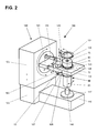
- FIG. 2 3 is a schematic representation of a metering device 100 with a metering unit 50, the metering device 100 having a receiving device 121 and a drive device 122 and a scale 145 having a weighing cell for detecting the metered metered material mass.
- the receiving device 121 is divided into a bearing part 131 and a pivot part 132, wherein the pivot part 132 is pivotally connected about a horizontal pivot axis Z with the bearing part 131.
- the bearing part 131 is rotatably connected to a base unit 120 about a horizontal rotation axis.
- the pivoting movements taking place in the predetermined direction of movement V are generated by a non-visible drive arranged in the base unit 120 and transmitted to the pivoting part 132 via a linkage 133.
- a first unit 123 is rotatably mounted in the pivot member 132 and connected via a belt 127 to a drive wheel of the drive device 122, so that rotational movements can be transmitted.
- the first unit 123 has a first recess 128, which is matched to the shape of the first means 72.
- a second unit 124 along a rigidly connected to the pivot member 132 guide rod 129 is linearly displaceable and designed to pivot about this.
- the second unit 124 can also be fixed to the guide rod 129.
- the second unit 124 has a second recess 130, which is tuned to the shape of the second means 92.
- FIG. 2 shows the metering device 100 not in operational state, but in the bamboosphase.
- the dosing unit 50 is inserted into the receiving device 121, which lingers in the illustrated loading position, or into a bore of the first unit 123.
- the annularly formed second unit 124 is subsequently pivoted to the metering unit 50 aligned and linearly displaced along the guide rod 129 until the actuator 90 passes through the second unit 124 and this rests on the second means 92 loosely.
- the second unit 124 may be rotated until the first means 72 in the first recess 128 and the second means 92 in the second recess 130 rests.
- the second unit 124 is fixed on the guide rod 129 and the receiving device 121 together with the dosing unit 50 is rotated about a horizontal axis of rotation, so that the outlet opening 75 is arranged directly above the inlet opening of a target vessel 146.
- the destination vessel 146 stands on a load receiver 147 of the balance 145.
- the receiving device 121 can be rotated as often as desired before dispensing or shaken in a shock-like manner by pivoting.
- the actuator 90 is not rotated relative to the receiving device 121 to open and close the metering unit 50, but the main body 71 with the removal vessel 60th
- the base unit 120 can be divided into a lower part 126 and a top 125, wherein the height adjustment of the upper part 125 to the lower part 126 is vertically displaceable.
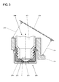
- FIG. 3 shows a metering unit 250 in a sectional elevation, the metering unit 250 having a removal vessel 260 and a metering head 270.
- the dosing head 270 corresponds in its construction exactly in the FIG. 1 shown dosing.
- the inner surface 277 of the bottom 278 is conical and not curved and thus has a line-shaped area, which appears in section as a straight line.
- the line-shaped area extends parallel to the direction of movement V of a parallel guided by means of parallel links 231, 232 receiving device 221.
- the receiving device 221 and the parallel links 231, 232 are part of a dosing device 200 shown only partially.
- the two parallel links 231, 232 are the same length, therefore essentially a linear movement in the direction of movement V and in the given angle ⁇ to the central longitudinal axis X of the outlet opening 275. Also in this embodiment, the predetermined angle ⁇ is measured between the line-shaped area and the central longitudinal axis, smaller than 90 °.
- the two parallel links 231, 232 may also have a different length, whereby the predetermined direction of movement V is a pivoting movement or rocking motion and the inner surface of the bottom of this pivoting movement must be adjusted, curved.
- FIG. 4 shows a schematic, three-dimensional representation of the dosing head 370 of a dosing unit with an outlet opening 375 in a further embodiment.
- the outlet opening 375 has a blade-shaped edge 376.
- This further embodiment essentially corresponds to that in the FIG. 1 already described embodiment.
- FIG. 4 clearly shows how the rotationally symmetrical inner surface 377 of the bottom 378 is designed.
- the circle center M of the circular arc R is aligned with the pivot axis Z arranged orthogonally and at a distance S from the central longitudinal axis X, which predetermines the direction of movement V.
- the circular arc R determines the rotationally symmetrical shaping of the inner surface 377 relative to the central longitudinal axis X of the dosing head 370. Accordingly, only a linear region of the inner surface 377 has the orientation according to the invention relative to the pivot axis Z, although the inner surface 377 has a continuous surface course starting from the circular arc R.
- a closure element 380 is arranged on its central longitudinal axis X.
- the end surface 381 of the closure element 380 is arranged for this purpose at an angle ⁇ to the central longitudinal axis X.
- the end face 381 of the closure element 380 or the closure element 380 itself can also be designed differently. Possible embodiments are for example in the EP 1 931 950 A1 . EP 1 931 951 A1 and in the EP 1 931 953 A1 disclosed.
- FIG. 5 shows a schematic, three-dimensional representation of the dosing 470 a dosing with an outlet 475 in another embodiment.
- the interior 473 of the dosing head 470 is bounded by a side wall and a bottom 478, the transition from the side wall to the bottom 478 lying in the horizontal sectional plane F and therefore the side wall is not shown.
- the circle center M of the circular arc R is aligned with the axis of rotation X orthogonal and arranged at a distance S pivot axis Z, which defines the direction of movement V.
- the inner surface 477 of the bottom 478 has a discontinuous surface profile, the point of discontinuity lying in the region of the circular arc R.
- FIG. 6 shows a schematic, three-dimensional representation of the dosing head 570 of a dosing unit with two outlet openings 575A, 575B in a further embodiment.
- closure elements On the representation of closure elements was omitted for the purpose of a better overview.
- the interior 573 of the dosing head 570 is bounded by a side wall 579 and a bottom 578, wherein the transition from the side wall 579 to the bottom 478 lies partially in the horizontal sectional plane F.
- the horizontal pivot axis Z is also arranged in the sectional plane F.
- the inner surface 577 of the bottom 578 is channel-shaped, so that not only a circle center M is present, but this extends over the entire length of the pivot axis Z out. Accordingly, each point of the inner surface 577 according to the invention is arranged on a circular arc R, the center of the circle M is arranged on the pivot axis Z.
- the central longitudinal axes XA, XB of the outlet openings 575A, 575B are each arranged at the same distance S to the pivot axis Z, which defines the direction of movement V. Furthermore, more than two outlet openings 575A, 575B can be present, which can be closed independently of one another or synchronously with closure elements.
- Embodiments with knowledge of the present invention can be provided, for example, by combining the features of the individual embodiments with each other and / or individual functional units of the embodiments are exchanged. So in the FIG. 5 disclosed discontinuous inner surface also in a dosing with multiple outlet openings, as in FIG. 6 is disclosed. Furthermore, the closure elements such as the slide are off FIG. 1 and the closure element FIG. 4 can be used in all embodiments. Accordingly, such combinations and alternatives are considered part of the invention.
Landscapes
- Physics & Mathematics (AREA)
- General Physics & Mathematics (AREA)
- Engineering & Computer Science (AREA)
- Mechanical Engineering (AREA)
- Fluid Mechanics (AREA)
- Medical Preparation Storing Or Oral Administration Devices (AREA)
- Basic Packing Technique (AREA)
- Loading And Unloading Of Fuel Tanks Or Ships (AREA)
- Feeding, Discharge, Calcimining, Fusing, And Gas-Generation Devices (AREA)
Abstract
Description
- Die Erfindung betrifft eine Dosiervorrichtung mit einer Aufnahmevorrichtung die in einer vorbestimmten Bewegungsrichtung bewegbar gelagert ist und eine auf diese Dosiervorrichtung abgestimmte, in die Aufnahmevorrichtung einsetzbare Dosiereinheit.
- Dosiervorrichtungen für fliessfähige Substanzen, beispielsweise für Pulver, Pasten oder Flüssigkeiten werden in vielen Bereichen der Industrie eingesetzt. Vorzugsweise weisen diese Dosiervorrichtungen eine Antriebsvorrichtung, eine Steuerung und eine Messvorrichtung zur Erfassung der ausdosierten Masse auf. Die Zuführung von fliessfähigen Substanzen beziehungsweise dem Dosiergut, kann entweder durch eine Versorgungsleitung oder durch eine auswechselbare Dosiereinheit erfolgen. Damit die Dosiereinheit in die Dosiervorrichtung eingesetzt werden kann, muss diese eine Aufnahmevorrichtung aufweisen.
- Eine Dosiereinheit weist im Wesentlichen ein Entnahmegefäss auf, welches das Dosiergut enthält und welches mit einem Dosierkopf verschlossen ist. Der Dosierkopf beinhaltet eine Auslassöffnung und ein Verschlusselement, mittels welchem die Auslassöffnung variabel verschliessbar ist. An Stelle des Entnahmegefässes kann der Dosierkopf auch mit einer Zufuhrvorrichtung versehen sein, beispielsweise mit einem Zufuhrschlauch.
- Eine Dosiervorrichtung mit einer Aufnahmevorrichtung für eine Dosiereinheit der vorgenannten Art wird in der
EP 1 959 244 A1 offenbart. Diese weist eine Aufnahmevorrichtung für eine Dosiereinheit auf, welche um eine horizontale Achse schwenkbar gelagert ist. Mittels eines Schlagmechanismus können oszillierende Schwenkbewegungen der Aufnahmevorrichtung erzeugt werden, wobei durch die Schwenkbewegungen pulverförmiges Dosiergut in der Dosiereinheit aufgelockert wird. Ferner werden durch die Schwenkbewegungen Pulverbrücken eingerissen, die den Zustrom von Dosiergut zur Auslassöffnung hin hemmen. Bei Pulverbrücken verkeilen sich die einzelnen Pulverpartikel gegenseitig zu einem bogenförmigen Deckel und stoppen so den kontinuierlichen Zufluss von Dosiergut zur Auslassöffnung. - Bei pulverförmigem Dosiergut mit beliebigen Kornformen und geringer Feuchte haben oszillierende Schwenkbewegung hervorragende Ergebnisse erbracht. Das in der Dosiereinheit verfüllte Dosiergut, welches durch eine lange Lagerungszeit, Transporterschütterungen oder durch Feuchtigkeitsaufnahme verfestigt worden ist, kann durch die Schwenkbewegungen in einen deutlich fliessfähigeren Zustand gebracht werden. Dies deshalb, weil durch die Schwenkbewegungen das Dosiergut im Entnahmegefäss aufgeworfen wird und eine lockere Aufschüttung des Dosierguts entsteht.
- Versuche haben jedoch gezeigt, dass trotz der Auflockerung des Dosiergutes das Dosiergut an der Innenwand des Dosierkopfs anhaftet, insbesondere im Bereich der Austragungsöffnung. Dies kann zur Behinderung des Austragungsvorganges führen.
- Die Aufgabe der vorliegenden Erfindung ist daher, eine Dosiereinheit zu schaffen, bei welcher möglichst wenig Dosiergut an der Innenwand des Dosierkopfs anhaftet.
- Diese Aufgabe wird mit einer Dosiereinheit und einer Dosiervorrichtung gelöst, welche die in den unabhängigen Patentansprüchen angegebenen Merkmale aufweisen.
- Eine erfindungsgemässe Dosiereinheit weist einen Innenraum auf, welcher durch eine Seitenwand und einen Boden begrenzt ist. Im Boden ist ferner eine Auslassöffnung ausgebildet. Die Dosiereinheit kann mit einer Aufnahmevorrichtung einer Dosiervorrichtung verbunden werden. Die Aufnahmevorrichtung ist in einer vorbestimmten Bewegungsrichtung bewegbar gelagert. Die Mittellängsachse der Auslassöffnung ist in einem vorgegebenen Winkel zur vorbestimmten Bewegungsrichtung ausgerichtet. Die dem Innenraum zugewandte Innenfläche des Bodens weist einen, von der Auslassöffnung ausgehenden, zumindest linienförmigen Bereich auf, der sich entlang der vorbestimmten Bewegungsrichtung erstreckt.
- Die erfindungsgemässe Ausbildung des Bodens in Abhängigkeit der Bewegungsrichtung führt dazu, dass bei Bewegungen der Aufnahmevorrichtung maximale Scherkräfte im zumindest linienförmigen Bereich zwischen der Innenwand und dem an dieser anhaftendem Dosiergut erreichbar sind. Da ferner die Mittellängsachse der Auslassöffnung in einem vorgegebenen Winkel zur Bewegungsrichtung ausgerichtet ist, rutscht das Dosiergut, durch die Scherkräfte von der Innenwand abgelöst, effizient durch die Auslassöffnung aus der Dosiereinheit. Der vorgegebene Winkel zwischen dem linienförmigen Bereich und der Mittellängsachse gemessen, ist kleiner als 90°.
- In einer ersten Ausgestaltung der erfindungsgemässen Dosiervorrichtung kann die vorbestimmte Bewegungsrichtung eine um eine horizontale Schwenkachse erfolgende Schwenkbewegung der Aufnahmevorrichtung sein. Dadurch muss der zumindest linienförmige Bereich der Innenwand ein Kreisbogen sein, der sich von der Mittellängsachse der Auslassöffnung ausgehend zur Seitenwand hin erstreckt. Der Kreismittelpunkt des Kreisbogens ist in orthogonalem Abstand zur Mittellängsachse der Auslassöffnung angeordnet und derart ausgerichtet, dass bei mit der Aufnahmevorrichtung verbundener Dosiereinheit der Kreismittelpunkt auf der Schwenkachse der Aufnahmevorrichtung angeordnet ist. Konkret kann dies dadurch erreicht werden, dass die Aufnahmevorrichtung Kupplungsmittel für mindestens eine Dosiereinheit aufweist, wobei durch die Kupplungsmittel sichergestellt wird, dass die Abstände der eingesetzten Dosiereinheit zur Schwenkachse in erfindungsgemässem Sinne eingestellt und/oder eingehalten werden können. Noch einfacher ist die Verwendung eines fest definierten Kupplungsmittels, auf welches die geometrischen Verhältnisse der Dosiereinheit ausgerichtet sind.
- Die Grösse des Krümmungsradius des Kreisbogens entspricht somit dem Radius der Schwenkbewegung. Dadurch dass die Schwenkachse im Abstand von der Mittellängsachse angeordnet ist, erfolgt die Bewegungsrichtung in einem vorgegebenen Winkel zur Mittellängsachse der Auslassöffnung. Aufgrund des Kreisbogens variiert logischerweise der vorgegebene Winkel in Abhängigkeit der Entfernung des betrachteten Tangentenpunkts des Kreisbogens von der Mittellängsachse der Auslassöffnung. Je weiter entfernt der betrachtete Tangentenpunkt von der Auslassöffnung gewählt ist, desto spitzer ist der vorgegebene Winkel.
- Die erfindungsgemässe Ausbildung des Bodens gemäss der ersten Ausgestaltung führt dazu, dass bei Schwenkbewegungen der Aufnahmevorrichtung im Bereich des Kreisbogens maximale Scherkräfte zwischen der Innenwand und dem an dieser anhaftendem Dosiergut erreichbar sind. Versuche mit mehreren Dosiergütern mit unterschiedlichsten Eigenschaften haben ergeben, dass durch die erfindungsgemässe Ausbildung der Innenfläche das Dosiergut durch die oszillierenden Schwenkbewegungen effizient von der Innenfläche ablöst und zur Auslassöffnung förderbar ist.
- Selbstverständlich kann der Krümmungsradius des Kreisbogens etwas vom Radius der Schwenkbewegungen abweichen. Eine gute Ablösung koagulierender Dosiergüter wurde auch erreicht, wenn die Grösse des Krümmungsradius nicht mehr als ± 10% vom Radius der Schwenkbewegung abweicht.
- In einer zweiten Ausführung ist die vorbestimmte Bewegungsrichtung eine Linearbewegung der Aufnahmevorrichtung. Erfindungsgemäss ist der zumindest linienförmige Bereich eine Gerade, die sich von der Mittellängsachse der Auslassöffnung ausgehend zur Seitenwand hin erstreckt.
- Ausgehend vom linienförmigen Bereich beider Ausführungen kann der Boden einen kontinuierlichen Flächenverlauf aufweisen. Um einen kontinuierlichen Flächenverlauf zu erreichen, kann die Innenwand beispielsweise bezogen auf die Auslassöffnung rotationssymmetrisch ausgebildet sein, wodurch eine trichterförmige, gewölbte oder kegelförmige Innenwand vorhanden ist.
- In Abhängigkeit der gewünschten Eigenschaften des Erfindungsgegenstandes kann der Boden ausgehend vom linienförmigen Bereich auch einen diskontinuierlichen Flächenverlauf aufweisen. Dadurch wird erreicht, dass in der Zone des linienförmigen Bereichs die grössten Scherkräfte entstehen und das Dosiergut in diese Zone zur Auslassöffnung gefördert wird.
- Selbstverständlich können im Boden einer Dosiereinheit mindestens zwei Auslassöffnungen ausgebildet sein, wobei der Boden von jeder Auslassöffnung ausgehend einen Kreisbogen aufweist und die Auslassöffnungen auf einer zur Schwenkachse parallelen Linie angeordnet sind.
- Vorzugsweise weist die Auslassöffnung eine schneidenförmige Kante auf. Insbesondere bei strangförmig austretenden Substanzen führt die schneidenförmige Kante zu einer besseren Abtrennung des Substanzstranges, da dieser infolge der Schwenkbewegungen und durch seine Massenträgheit von der Kante zerstückelt wird.
- Die Auslassöffnung kann ferner einen beliebigen Querschnitt aufweisen, vorzugsweise ist er dreieckig, viereckig oder rund.
- In der erfindungsgemässen Dosiereinheit können ferner verschiedene Verschlussorgane verwendet werden. Beispielsweise kann die Querschnittfläche der Auslassöffnung mit einem Schieber variabel verschlossen beziehungsweise geöffnet werden. Auch der Schieber kann eine Schneidkante aufweisen, die zu einer besseren Abtrennung des Substanzstranges führt, da dieser infolge der Schwenkbewegungen und durch seine Massenträgheit von der Schneidkante zerstückelt wird.
- Vorzugsweise ist der Schieber orthogonal zur Mittellängsachse der Auslassöffnung verschiebbar angeordnet und weist eine gerade, sichelförmige oder V-förmige Verschlusskante oder eine dreieckige, viereckige oder runde Durchlassöffnung auf.
- Anstelle eines Schiebers kann die Querschnittfläche der Auslassöffnung auch mit einem entlang der Mittellängsachse der Auslassöffnung linear verschiebbaren Verschlusselement variabel verschlossen beziehungsweise geöffnet werden.
- Damit eine Dosiereinheit mit der den Bewegungen erfindungsgemäss angepassten Innenkontur einsetzbar ist, muss eine Dosiervorrichtung mit einer entsprechend bewegbar ausgestalteten Aufnahmevorrichtung zur Aufnahme einer Dosiereinheit vorhanden sein. Wie weiter oben aufgeführt, kann die Aufnahmevorrichtung je nach Innenkontur der Dosiereinheit schwenkbar oder linear bewegbar ausgestaltet sein.
- Ferner weist die Dosiervorrichtung einen Schlagmechanismus zur Erzeugung oszillierender Bewegungen der Aufnahmevorrichtung in der vorgegebenen Bewegungsrichtung auf. Die rasche Abfolge von sehr kurzen Bewegungen führt zu einer Ablösung des Dosiergutes im Grenzbereich zur Innenwand des Dosierkopfes und verhindert das Wiederanhaften der Dosiergutpartikel. Je nach Ausgestaltung des Schlagmechanismus und der bewegbar gelagerten Aufnahmevorrichtung sind die Amplituden der oszillierenden Bewegungen so klein, dass diese eher Schockwellen gleichen. Selbstverständlich kann die Oberfläche des Bodens zur Auslassöffnung hin mit speziellen Mitteln zur Förderung des Dosiergutes ausgestaltet sein. Diese Mittel können eine fischschuppenartige Strukturierung, Rillen mit Sägezahnprofil, sich in eine bestimmte Bewegungsrichtung aufrichtende Fasern, Antihaftbeschichtungen und dergleichen mehr sein.
- Die Aufnahmevorrichtung kann ferner um eine horizontale Drehachse drehbar sein. Durch diese Ausgestaltung kann eine Dosiereinheit über Kopf gedreht werden. Dies hat den Vorteil, dass die Aufnahmevorrichtung in eine definierte Beschickungsposition gedreht werden kann, in der eine Dosiereinheit auf einfache Weise in die Aufnahmevorrichtung einsetzbar ist. Zudem kann das Dosiergut durch die Drehbewegung durchmischt und aufgelockert werden. Sobald der Dosiervorgang abgeschlossen ist, führt die Drehbewegung in die Beschickungsposition dazu, dass alles Dosiergut in das Entnahmegefäss zurückfällt. Die Bedienungsperson oder eine Beschickungsvorrichtung kann die Dosiereinheit anschliessend aus der Aufnahmevorrichtung entfernen und in dieser vorgegebenen Lage einlagern. Bei der Einlagerung der Dosiereinheit wird das Dosiergut von der Auslassöffnung ferngehalten. Selbst wenn das Dosiergut zur Koagulation oder Sedimentation neigt, verklumpt die Substanz im Bereich des Entnahmegefäss-Bodens und "zementiert" nicht die Auslassöffnung zu.
- Einzelheiten der erfindungsgemässen Dosiervorrichtung ergeben sich anhand der Beschreibung der in den Zeichnungen dargestellten Ausführungsbeispiele. Es zeigen:
- Fig. 1
- eine Dosiereinheit in geschnittenem Aufriss, wobei die Dosiereinheit ein Entnahmegefäss und einen Dosierkopf aufweist, sowie eine Schwenkachse einer nicht dargestellten Aufnahmevorrichtung, auf welcher der Kreismittelpunkt eines Kreisbogens angeordnet ist;
- Fig. 2
- eine schematische, dreidimensionale Darstellung einer Dosiervorrichtung mit einer Aufnahmevorrichtung, in die eine Dosiereinheit gemäss der
Figur 1 eingesetzt ist; - Fig. 3
- eine Dosiereinheit in geschnittenem Aufriss, wobei die Dosiereinheit ein Entnahmegefäss und einen Dosierkopf aufweist, sowie eine mittels Parallellenker linear geführte Aufnahmevorrichtung, zu deren Bewegungsrichtung der linienförmige Bereich des Bodens der Dosiereinheit parallel angeordnet ist;
- Fig. 4
- eine schematische, dreidimensionale Darstellung des Dosierkopfs einer Dosiereinheit mit einer Auslassöffnung und mit einem entlang der Mittellängsachse der Auslassöffnung geführten Verschlusselement sowie mit einer kontinuierlichen Innenfläche;
- Fig. 5
- eine schematische, dreidimensionale Darstellung des Dosierkopfs einer Dosiereinheit mit einer Auslassöffnung und einer diskontinuierlichen Innenfläche;
- Fig. 6
- eine schematische, dreidimensionale Darstellung des Dosierkopfs einer Dosiereinheit mit zwei Auslassöffnungen.
- Die
Figur 1 zeigt eine Dosiereinheit 50 mit einem Dosierkopf 70 in geschnittenem Aufriss. Die Dosiereinheit 50 ist in ihrer Gebrauchslage dargestellt, das heisst in der Lage, in welcher das Entnahmegefäss 60 mit dem Dosierkopf 70 verbunden ist und Dosiergut ausgetragen werden kann. Wenn Dosiergut aus dem Dosierkopf 70 austreten soll, muss die Dosiereinheit 50 wie dargestellt, kopfüber gedreht sein, so dass der Dosierkopf 70 bezogen auf die Richtung der Schwerkraft unten und das Entnahmegefäss 60 oben ist. Der Dosierkopf 70 weist einen Grundkörper 71 auf, mit dem das Entnahmegefäss 60 lösbar verbunden ist. An Stelle des Entnahmegefässes 60 kann auch ein Verschlussdeckel vorhanden sein, so dass ein verfüllter, einsatzbereiter Dosierkopf 70 gleichzeitig den Vorrat an Dosiergut beinhaltet. Ferner sind auch andere Zuführvorrichtungen mit dem Grundkörper 71 verbindbar, beispielsweise ein Trichter, ein Tank, ein Silo oder ein Zuführschlauch. Der Grundkörper 71 weist ferner ein erstes Mittel 72 zur Übertragung eines Drehmoments auf. Selbstverständlich muss das erste Mittel 72 nicht zwingend den inFigur 1 dargestellten Vorsprung aufweisen um einen Formschluss mit einer nicht dargestellten ersten Einheit zu ermöglichen. Der Grundkörper 71 kann als erstes Mittel 72 auch eine Klemmfläche aufweisen die kraftschlüssig, beispielsweise mit einer Klemmpratze oder Spannzange, mit der ersten Einheit verbunden werden kann. Der Grundkörper 71 wird fast vollständig von einem becherförmigen Stellglied 90 umgeben, welches um seine Mittellängsachse X drehbar mit dem Grundkörper 71 verbunden ist. Das Stellglied 90 weist stirnseitig einen Durchbruch 91 und ein zweites Mittel 92 zur Übertragung eines Drehmoments auf. Zwischen dem Grundkörper 71 und dem Stellglied 90 ist ein Schieber 80 angeordnet, welcher in der offenen Stellung dargestellt ist und eine Durchlassöffnung 82 beinhaltet. - Der Grundkörper 71 weist eine zylindrische Grundform auf. Im Grundkörper 71 ist ein Innenraum 73 ausgebildet, welcher durch einen Boden 78 und eine zylindrische Seitenwand 79 begrenzt wird. Die Seitenwand 79 des Grundkörpers 71 bildet die Anschlussstelle für das Entnahmegefäss 60. Auf der Mittellängsachse X des Grundkörpers 71 beziehungsweise des Dosierkopfs 50, ist eine Auslassöffnung 75 im Boden 78 angeordnet. Die Auslassöffnung 75 ist mit der Anschlussstelle für das Entnahmegefäss 60 verbunden, so dass im Betriebszustand der Dosiereinheit 50 Dosiergut vom Entnahmegefäss 60 zur Auslassöffnung 75 gelangen kann. Die dem Innenraum 73 des Grundkörpers 71 zugewandte Innenfläche 77 des Bodens 78 ist gewölbt ausgebildet und weist einen linienförmigen Bereich in der Form eines Kreisbogens R auf, dessen Kreismittelpunkt M auf der Schwenkachse Z einer nicht dargestellten Aufnahmevorrichtung angeordnet ist. Die Schwenkachse Z gibt die Bewegungsrichtung V vor. Die Schwenkachse Z ist orthogonal zur Zeichnungsebene und zudem parallel im Abstand S zur Mittellängsachse X des Dosierkopfs angeordnet. Der Kreisbogen R erstreckt sich von der Mittellängsachse X der Auslassöffnung 75 ausgehend zur Seitenwand 79 hin. Dadurch dass die Schwenkachse Z im Abstand S von der Mittellängsachse X angeordnet ist, erfolgt die vorgegebene Bewegungsrichtung V in einem vorgegebenen Winkel α zur Mittellängsachse der Auslassöffnung. Der vorgegebene Winkel α zwischen dem linienförmigen Bereich und der Mittellängsachse X gemessen, ist kleiner als 90°.
- Da die Innenfläche 77 des Bodens 78 in Bezug auf die Mittellängsachse X der Auslassöffnung 75 rotationssymmetrisch ausgebildet ist, gilt der vorangehend beschriebene Bezug des Kreismittelpunkts M zur Schwenkachse Z nur für einen linienförmigen Bereich der Innenfläche 77. Dies ist jedoch ausreichend, da das Dosiergut sich ausgehend von diesem linienförmigen Bereich von der Innenfläche 77 ablöst und das daneben anhaftende Dosiergut mitreisst.
- Die dem Innenraum 73 abgewandte Stirnfläche 74 des Bodens 78 weist eine, die Auslassöffnung 75 umlaufende Kuppe 76 auf. Der Schieber 80 ist im Wesentlichen ein flaches Teil, welcher parallel zur Stirnfläche 74 in geeigneter Weise am Grundkörper 71 linear geführt ist. Das Stellglied 90 weist ein nicht einsehbares Kurvensegment auf, mittels welchem eine auf das Stellglied 90 übertragene Drehbewegung in eine auf den Schieber 80 wirkende lineare Bewegung umgewandelt wird.
- Mittels des linear verschiebbaren Schiebers 80 kann dessen Durchlassöffnung 82 mit der Auslassöffnung 75 variabel in Übereinstimmung gebracht werden, so dass der Durchlassquerschnitt abhängig vom Drehwinkel des Stellgliedes 90 relativ zum Grundkörper 71, frei wählbar ist. Selbstverständlich kann die Durchlassöffnung 82 einen beliebigen Querschnitt aufweisen, beispielsweise eine dreieckige, rechteckige, quadratische oder ovale Querschnittform. Wie in der
US 7,284,574 B2 bereits ausführlich beschrieben, eignet sich die dreieckige Querschnittform besonders, da der Durchlassquerschnitt des Dosierkopfs 70 mittels einer relativen Verschiebung des Schiebers 80 und dessen Durchlassöffnung 82 relativ zur Auslassöffnung 75 bis auf den Durchmesser eines einzelnen Partikels des Dosiergutes angepasst werden kann. Dementsprechend sind nicht nur ein in der Menge variabel einstellbarer Dosiergutstrom aus der Dosiereinheit 50 ausdosierbar, sondern auch einzelne Partikel. Vorzugsweise weist die Durchlassöffnung 82 eine Schneidkante 83 auf, die zu einer besseren Abtrennung des Substanzstranges führt, da dieser infolge der Schwenkbewegungen und durch seine Massenträgheit von der Schneidkante 83 zerstückelt wird. - Die Abmessungen des Stellgliedes 90 sind derart auf die Dicke des Schiebers 80 und die Abmessungen des Grundkörpers 71 abgestimmt, dass der Schieber 80 mit leichter Presskraft gegen die Kuppe 76 gepresst ist. Um eine ausreichende Abdichtung zwischen dem Entnahmegefäss 60 und dem Grundkörper 71 zu erreichen, kann im Innenraum 73 ein Dichtring 69 ausgebildet oder eingesetzt sein.
- In den
Figuren 1 und4 bis 6 ist der Kreisbogen R mittels eines Pfeils dargestellt, dessen Spitze auf den eigentlichen Kreisbogen R weist. Diese Darstellungsart wurde gewählt, um die Verbindung zwischen dem Kreismittelpunkt M, welcher auf der Schwenkachse Z angeordnet ist, und dem Kreisbogen R hervorzuheben. Die Länge des mit R bezeichneten Pfeils entspricht somit auch dem Radius des Kreisbogens R. - In
Figur 2 ist schematisch in dreidimensionaler Ansicht eine Dosiervorrichtung 100 mit einer Dosiereinheit 50 dargestellt, wobei die Dosiervorrichtung 100 eine Aufnahmevorrichtung 121 und eine Antriebsvorrichtung 122 sowie eine Waage 145 mit einer Wägezelle zur Erfassung der ausdosierten Dosiergutmasse aufweist. Die Aufnahmevorrichtung 121 ist in einen Lagerteil 131 und in einen Schwenkteil 132 unterteilt, wobei der Schwenkteil 132 um eine horizontale Schwenkachse Z schwenkbar mit dem Lagerteil 131 verbunden ist. Das Lagerteil 131 ist mit einer Grundeinheit 120 um eine horizontale Drehachse drehbar verbunden. Die in der vorgegebenen Bewegungsrichtung V erfolgenden Schwenkbewegungen werden von einem in der Grundeinheit 120 angeordneten, nicht sichtbaren Antrieb erzeugt und über ein Gestänge 133 auf das Schwenkteil 132 übertragen. - Eine erste Einheit 123 ist drehbar im Schwenkteil 132 gelagert und über einen Riemen 127 mit einem Antriebsrad der Antriebsvorrichtung 122 verbunden, so dass Drehbewegungen übertragen werden können. Die erste Einheit 123 weist eine erste Aussparung 128 auf, die auf die Form des ersten Mittels 72 abgestimmt ist. Wie die Doppelpfeile andeuten, ist eine zweite Einheit 124 entlang eines mit dem Schwenkteil 132 starr verbundenen Führungsstabes 129 linear verschiebbar und um diesen verschwenkbar ausgestaltet. Ferner ist die zweite Einheit 124 auch am Führungsstab 129 fixierbar. Die zweite Einheit 124 weist eine zweite Aussparung 130 auf, die auf die Form des zweiten Mittels 92 abgestimmt ist.
-
Figur 2 zeigt die Dosiervorrichtung 100 nicht in betriebsbereitem Zustand, sondern in der Einrichtungsphase. In der Einrichtungsphase wird die Dosiereinheit 50 in die in der dargestellten Beschickungsposition verweilenden Aufnahmevorrichtung 121 beziehungsweise in eine Bohrung der ersten Einheit 123 eingesetzt. Zur Erstellung der vollständigen Betriebsbereitschaft der Dosiervorrichtung 100 wird hernach die ringförmig ausgebildete zweite Einheit 124 mittels Verschwenken zur Dosiereinheit 50 ausgerichtet und dem Führungsstab 129 entlang linear verschoben, bis das Stellglied 90 durch die zweite Einheit 124 hindurchreicht und diese auf dem zweiten Mittel 92 lose aufliegt. Nun kann die zweite Einheit 124 solange gedreht werden, bis das erste Mittel 72 in der ersten Aussparung 128 und das zweite Mittel 92 in der zweiten Aussparung 130 ruht. Anschliessend wird die zweite Einheit 124 am Führungsstab 129 fixiert und die Aufnahmevorrichtung 121 mitsamt der Dosiereinheit 50 um eine horizontale Drehachse gedreht, so dass die Auslassöffnung 75 unmittelbar über der Einlassöffnung eines Zielgefässes 146 angeordnet ist. Das Zielgefäss 146 steht auf einem Lastaufnehmer 147 der Waage 145. Selbstverständlich kann zur Auflockerung des Dosiergutes die Aufnahmevorrichtung 121 vor dem Dosieren beliebig oft gedreht oder durch Verschwenken schockartig geschüttelt werden. Wie aus derFigur 2 klar ersichtlich ist, wird zum öffnen und schliessen der Dosiereinheit 50 nicht das Stellglied 90 relativ zur Aufnahmevorrichtung 121 gedreht, sondern der Grundkörper 71 mit dem Entnahmegefäss 60. - Um nach dem Dosiervorgang die Dosiereinheit 50 aus der Aufnahmevorrichtung 121 zu entfernen, werden die vorangehend beschriebenen Schritte im Wesentlichen in umgekehrter Reihenfolge durchgeführt.
- Damit Zielgefässe 146 mit unterschiedlicher Höhe verwendet werden können, kann die Grundeinheit 120 in ein Unterteil 126 und in ein Oberteil 125 aufgeteilt sein, wobei zur Höhenverstellung das Oberteil 125 zum Unterteil 126 vertikal verschiebbar ist.
-
Figur 3 zeigt eine Dosiereinheit 250 in geschnittenem Aufriss, wobei die Dosiereinheit 250 ein Entnahmegefäss 260 und einen Dosierkopf 270 aufweist. Der Dosierkopf 270 entspricht in seinem Aufbau genau dem in derFigur 1 dargestellten Dosierkopf. Der einzige Unterschied liegt darin, dass in derFigur 3 die Innenfläche 277 des Bodens 278 kegelförmig und nicht gewölbt ausgebildet ist und somit einen linienförmigen Bereich aufweist, der im Schnitt als Gerade erscheint. Der linienförmige Bereich erstreckt sich parallel zur Bewegungsrichtung V einer mittels Parallellenker 231, 232 linear geführten Aufnahmevorrichtung 221. Die Aufnahmevorrichtung 221 und die Parallellenker 231, 232 sind Teil einer nur teilweise dargestellten Dosiervorrichtung 200. Die beiden Parallellenker 231, 232 sind gleich lang, deshalb erfolgt im Wesentlichen eine lineare Bewegung in der Bewegungsrichtung V und im vorgegebenen Winkel α zur Mittellängsachse X der Auslassöffnung 275. Auch bei diesem Ausführungsbeispiel ist der vorgegebene Winkel α zwischen dem linienförmigen Bereich und der Mittellängsachse gemessen, kleiner 90°. - Selbstverständlich können die beiden Parallellenker 231, 232 auch eine unterschiedliche Länge aufweisen, wodurch die vorbestimmte Bewegungsrichtung V eine Schwenkbewegung beziehungsweise Schaukelbewegung ist und die Innenfläche des Bodens dieser Schwenkbewegung angepasst, gewölbt sein muss.
-
Figur 4 zeigt eine schematische, dreidimensionale Darstellung des Dosierkopfs 370 einer Dosiereinheit mit einer Auslassöffnung 375 in einer weiteren Ausführung. Die Auslassöffnung 375 weist eine schneidenförmige Kante 376 auf. Diese weitere Ausführung entspricht im Wesentlichen der in derFigur 1 bereits beschriebenen Ausgestaltung. InFigur 4 ist deutlich ersichtlich, wie die rotationssymmetrische Innenfläche 377 des Bodens 378 ausgestaltet ist. Der Kreismittelpunkt M des Kreisbogens R ist auf die von der Mittellängsachse X orthogonal und im Abstand S angeordnete Schwenkachse Z ausgerichtet, die die Bewegungsrichtung V vorgibt. Der Kreisbogen R bestimmt die auf die Mittellängsachse X des Dosierkopfs 370 bezogene, rotationssymmetrische Formgebung der Innenfläche 377. Demzufolge weist nur ein linienförmiger Bereich der Innenfläche 377 die erfindungsgemässe Ausrichtung zur Schwenkachse Z auf, obwohl die Innenfläche 377 ausgehend vom Kreisbogen R einen kontinuierlichen Flächenverlauf aufweist. - Im Innenraum 373 des Dosierkopfs 370 ist auf dessen Mittellängsachse X ein Verschlusselement 380 angeordnet. Durch lineare Verschiebung des Verschlusselementes 380 entlang der Mittellängsachse X kann die Auslassöffnung 375 variabel verschlossen werden. Die Endfläche 381 des Verschlusselementes 380 ist zu diesem Zweck unter einem Winkel β zur Mittellängsachse X angeordnet. Selbstverständlich kann die Endfläche 381 des Verschlusselements 380 oder das Verschlusselement 380 selbst auch anders ausgestaltet sein. Mögliche Ausgestaltungen sind beispielsweise in der
EP 1 931 950 A1 ,EP 1 931 951 A1 und in derEP 1 931 953 A1 offenbart. -
Figur 5 zeigt eine schematische, dreidimensionale Darstellung des Dosierkopfs 470 einer Dosiereinheit mit einer Auslassöffnung 475 in einer weiteren Ausführung. Auf die Darstellung eines Verschlusselements wurde Zwecks einer besseren Übersicht verzichtet. Wie in den vorangehend beschriebenen Ausführungen wird der Innenraum 473 des Dosierkopfs 470 durch eine Seitenwand und einen Boden 478 begrenzt, wobei der Übergang von der Seitenwand zum Boden 478 in der horizontalen Schnittebene F liegt und deshalb die Seitenwand nicht dargestellt ist. Der Kreismittelpunkt M des Kreisbogens R ist auf die von der Mittellängsachse X orthogonal und im Abstand S angeordnete Schwenkachse Z ausgerichtet, die die Bewegungsrichtung V vorgibt. Die Innenfläche 477 des Bodens 478 weist einen diskontinuierlichen Flächenverlauf auf, wobei die Stelle der Diskontinuität im Bereich des Kreisbogens R liegt. -
Figur 6 zeigt eine schematische, dreidimensionale Darstellung des Dosierkopfs 570 einer Dosiereinheit mit zwei Auslassöffnungen 575A, 575B in einer weiteren Ausführung. Auf die Darstellung von Verschlusselementen wurde Zwecks einer besseren Übersicht verzichtet. Wie in den vorangehend beschriebenen Ausführungen wird der Innenraum 573 des Dosierkopfs 570 durch eine Seitenwand 579 und einen Boden 578 begrenzt, wobei der Übergang von der Seitenwand 579 zum Boden 478 teilweise in der horizontalen Schnittebene F liegt. Die horizontale Schwenkachse Z ist ebenfalls in der Schnittebene F angeordnet. Anders als bei den vorhergehenden Beispielen ist die Innenfläche 577 des Bodens 578 rinnenförmig ausgebildet, so dass nicht nur ein Kreismittelpunkt M vorhanden ist, sondern sich dieser über die gesamte Länge der Schwenkachse Z hin erstreckt. Dem entsprechend ist jeder Punkt der Innenfläche 577 erfindungsgemäss auf einem Kreisbogen R angeordnet, dessen Kreismittelpunkt M auf der Schwenkachse Z angeordnet ist. Wie aus derFigur 6 ersichtlich ist, sind die Mittellängsachsen XA, XB der Auslassöffnungen 575A, 575B je im gleichen Abstand S zur Schwenkachse Z angeordnet, welche die Bewegungsrichtung V vorgibt. Ferner können auch mehr als zwei Auslassöffnungen 575A, 575B vorhanden sein, welche unabhängig voneinander oder synchron mit Verschlusselementen verschliessbar sind. - Obwohl die Erfindung durch die Darstellung spezifischer Ausführungsbeispiele beschrieben worden ist, ist es offensichtlich, dass zahlreiche weitere
- Ausführungsvarianten in Kenntnis der vorliegenden Erfindung geschaffen werden können, beispielsweise indem die Merkmale der einzelnen Ausführungsbeispiele miteinander kombiniert und/oder einzelne Funktionseinheiten der Ausführungsbeispiele ausgetauscht werden. So kann die in der
Figur 5 offenbarte diskontinuierliche Innenfläche auch in einem Dosierkopf mit mehreren Auslassöffnungen, wie dies inFigur 6 offenbart ist, verwendet werden. Ferner sind die Verschlusselemente wie beispielsweise der Schieber ausFigur 1 und das Verschlusselement ausFigur 4 in allen Ausführungsbeispielen einsetzbar. Dementsprechend werden solche Kombinationen und Alternativen als Teil der Erfindung betrachtet. -
- 250, 50
- Dosiereinheit
- 260, 60
- Entnahmegefäss
- 69
- Dichtring
- 570, 470, 370, 270, 70
- Dosierkopf
- 71
- Grundkörper
- 72
- erste Mittel
- 573, 473, 373, 73
- Innenraum
- 74
- Stirnfläche
- 575A, 575B, 475, 375, 275, 75
- Auslassöffnung
- 76
- Kuppe
- 577, 477, 377, 277, 77
- Innenfläche
- 578,478,378,278,78
- Boden
- 579, 279, 79
- Seitenwand
- 80
- Schieber
- 82
- Durchlassöffnung
- 83
- Schneidkante
- 90
- Stellglied
- 91
- Durchbruch
- 92
- zweites Mittel
- 200, 100
- Dosiervorrichtung
- 120
- Grundeinheit
- 221, 121
- Aufnahmevorrichtung
- 122
- Antriebsvorrichtung
- 123
- erste Einheit
- 124
- zweite Einheit
- 125
- Oberteil
- 126
- Unterteil
- 127
- Riemen
- 128
- erste Aussparung
- 129
- Führungsstab
- 130
- zweite Aussparung
- 131
- Lagerteil
- 132
- Schwenkteil
- 133
- Gestänge
- 145
- Waage
- 146
- Zielgefäss
- 147
- Lastaufnehmer
- 232,231
- Parallellenker
- 376
- schneidenförmige Kante
- 380
- Verschlusselement
- 381
- Endfläche
- F
- Schnittebene
- M
- Kreismittelpunkt
- R
- Kreisbogen
- S
- Abstand
- V
- Bewegungsrichtung
- XB, XA, X
- Mittellängsachse
- Z
- Schwenkachse
Claims (16)
- Dosiereinheit (50, 250) mit einem Innenraum (73, 373, 473, 573), welcher durch eine Seitenwand (79, 279, 579) und einen Boden (78, 278, 378, 478, 578) begrenzt ist sowie mit einer im Boden (78, 278, 378, 478, 578) ausgebildeten Auslassöffnung (75, 275, 375, 475, 575A, 575B), wobei die Dosiereinheit (50, 250) mit einer Aufnahmevorrichtung (121, 221) einer Dosiervorrichtung (100, 200) verbindbar ist und die Aufnahmevorrichtung (121, 221) in einer vorbestimmten Bewegungsrichtung (V) bewegbar gelagert ist, dadurch gekennzeichnet, dass die dem Innenraum (73, 373, 473, 573) zugewandte Innenfläche des Bodens (78, 278, 378, 478, 578) einen von der Auslassöffnung (75, 275, 375, 475, 575A, 575B) ausgehenden, zumindest linienförmigen Bereich aufweist der sich entlang der vorbestimmten Bewegungsrichtung (V) erstreckt und die Mittellängsachse (X) der Auslassöffnung (75, 275, 375, 475, 575A, 575B) in einem vorgegebenen Winkel (α) zur vorbestimmten Bewegungsrichtung (V) ausgerichtet ist, wobei der vorgegebene Winkel (α) zwischen dem linienförmigen Bereich und der Mittellängsachse (X) gemessen, kleiner 90° ist.
- Dosiereinheit (50, 250) nach Anspruch 1, dadurch gekennzeichnet, dass die vorbestimmte Bewegungsrichtung (V) eine um eine horizontale Schwenkachse (Z) erfolgende Schwenkbewegung der Aufnahmevorrichtung (121, 221) ist und der zumindest linienförmige Bereich ein Kreisbogen (R) ist, der sich von der Mittellängsachse (X) der Auslassöffnung (75, 275, 375, 475, 575A, 575B) ausgehend zur Seitenwand (79, 279, 579) hin erstreckt, wobei der Kreismittelpunkt (M) des Kreisbogens (R) in orthogonalem Abstand (S) zur Mittellängsachse (X) der Auslassöffnung (75, 275, 375, 475, 575A, 575B) angeordnet und derart ausgerichtet ist, dass bei mit der Aufnahmevorrichtung (121, 221) verbundener Dosiereinheit (50, 250) der Kreismittelpunkt (M) auf der Schwenkachse (Z) der Aufnahmevorrichtung (121, 221) angeordnet ist.
- Dosiereinheit (50, 250) nach Anspruch 2, dadurch gekennzeichnet, dass der Kreisbogen (R) einen Krümmungsradius aufweist, dessen Gösse nicht mehr als
± 10% vom Radius der Schwenkbewegung im Bereich des Kreisbogens (R) abweicht. - Dosiereinheit (50, 250) nach Anspruch 1, dadurch gekennzeichnet, dass die vorbestimmte Bewegungsrichtung (V) eine Linearbewegung der Aufnahmevorrichtung (121, 221) ist und der zumindest linienförmige Bereich eine zur vorbestimmten Bewegungsrichtung (V) parallelen Gerade ist, die sich von der Mittellängsachse (X) der Auslassöffnung (75, 275, 375, 475, 575A, 575B) ausgehend zur Seitenwand (79, 279, 579) hin erstreckt.
- Dosiereinheit (50, 250) nach einem der Ansprüche 1 bis 4, dadurch gekennzeichnet, dass ausgehend vom zumindest linienförmigen Bereich der Boden (78, 278, 378, 578) einen kontinuierlichen Flächenverlauf aufweist.
- Dosiereinheit (50, 250) nach einem der Ansprüche 1 bis 4, dadurch gekennzeichnet, dass ausgehend vom zumindest linienförmigen Bereich der Boden (478) einen diskontinuierlichen Flächenverlauf aufweist.
- Dosiereinheit (50, 250) nach einem der Ansprüche 1 bis 6, dadurch gekennzeichnet, dass mindestens zwei Auslassöffnungen (75, 275, 375, 475, 575A, 575B) im Boden (78, 278, 378, 478, 578) ausgebildet sind, wobei der Boden (78, 278, 378, 478, 578) von jeder Auslassöffnung (75, 275, 375, 475, 575A, 575B) ausgehend einen zumindest linienförmigen Bereich aufweist die sich entlang der vorbestimmten Bewegungsrichtung (V) erstrecken.
- Dosiereinheit (50, 250) nach einem der Ansprüche 1 bis 7, dadurch gekennzeichnet, dass die Auslassöffnung (75, 275, 375, 475, 575A, 575B) eine schneidenförmige Kante (376) aufweist.
- Dosiereinheit (50, 250) nach einem der Ansprüche 1 bis 8, dadurch gekennzeichnet, dass die Auslassöffnung (75, 275, 375, 475, 575A, 575B) einen dreieckigen, viereckigen oder runden Querschnitt aufweist.
- Dosiereinheit (50, 250) nach einem der Ansprüche 1 bis 9, dadurch gekennzeichnet, dass die Querschnittfläche der Auslassöffnung (75, 275, 375, 475, 575A, 575B) mit einem Schieber (80) variabel verschliessbar ist.
- Dosiereinheit (50, 250) nach Anspruch 10, dadurch gekennzeichnet, dass der Schieber (80) orthogonal zur Mittellängsachse (X) der Auslassöffnung (75, 275, 375, 475, 575A, 575B) verschiebbar angeordnet ist und eine gerade, sichelförmige oder V-förmige Verschlusskante oder eine dreieckige, viereckige oder runde Durchlassöffnung (82) aufweist.
- Dosiereinheit (50, 250) nach Anspruch 11, dadurch gekennzeichnet, dass die Durchlassöffnung (82) eine Schneidkante (83) aufweist.
- Dosiereinheit (50, 250) nach einem der Ansprüche 1 bis 9, dadurch gekennzeichnet, dass die Querschnittfläche der Auslassöffnung (75, 275, 375, 475, 575A, 575B) mit einem entlang der Mittellängsachse (X) der Auslassöffnung (75, 275, 375, 475, 575A, 575B) linear verschiebbaren Verschlusselement (380) variabel verschliessbar ist.
- Dosiervorrichtung (100, 200) mit einer Aufnahmevorrichtung (121, 221) zur Aufnahme einer Dosiereinheit (50, 250) nach einem der Ansprüche 1 bis 13, welche Dosiereinheit (50, 250) einen durch einen Boden (78, 278, 378, 478, 578) und eine Seitenwand (79, 279, 579) begrenzten Innenraum (73, 373, 473, 573) und eine im Boden (78, 278, 378, 478, 578) ausgebildete Auslassöffnung (75, 275, 375, 475, 575A, 575B) aufweist und welche Aufnahmevorrichtung (121, 221) in einer vorbestimmten Bewegungsrichtung (V) bewegbar gelagert ist, dadurch gekennzeichnet, dass die vorbestimmte Bewegungsrichtung (V) in einem vorgegebenen Winkel (α) zur Mittellängsachse (X) der Auslassöffnung (75, 275, 375, 475, 575A, 575B) und entlang einem zumindest linienförmigen Bereich der dem Innenraum (73, 373, 473, 573) zugewandten Innenfläche des Bodens (78, 278, 378, 478, 578) erfolgt, welcher linienförmige Bereich sich von der Mittellängsachse (X) der Auslassöffnung (75, 275, 375, 475, 575A, 575B) ausgehend zur Seitenwand (79, 279, 579) hin erstreckt und der vorgegebene Winkel (α) zwischen dem linienförmigen Bereich und der Mittellängsachse (X) gemessen, kleiner 90° ist.
- Dosiervorrichtung (100, 200) nach Anspruch 14, dadurch gekennzeichnet, dass die Dosiervorrichtung (100, 200) einen Schlagmechanismus (133) zur Erzeugung oszillierender Bewegungen der Aufnahmevorrichtung (121, 221) in der vorgegebenen Bewegungsrichtung (V) aufweist.
- Dosiervorrichtung (100, 200) nach Anspruch 14 oder 15, dadurch gekennzeichnet, dass die Aufnahmevorrichtung (121, 221) ferner um eine horizontal angeordnete Drehachse drehbar ist.
Priority Applications (4)
| Application Number | Priority Date | Filing Date | Title |
|---|---|---|---|
| EP10192661.6A EP2458345B1 (de) | 2010-11-26 | 2010-11-26 | Dosiersystem |
| US13/298,626 US8915401B2 (en) | 2010-11-26 | 2011-11-17 | Dosage-dispensing device |
| JP2011251471A JP5868134B2 (ja) | 2010-11-26 | 2011-11-17 | 用量分注装置 |
| CN201110401253.6A CN102530405B (zh) | 2010-11-26 | 2011-11-25 | 剂量分配设备 |
Applications Claiming Priority (1)
| Application Number | Priority Date | Filing Date | Title |
|---|---|---|---|
| EP10192661.6A EP2458345B1 (de) | 2010-11-26 | 2010-11-26 | Dosiersystem |
Publications (2)
| Publication Number | Publication Date |
|---|---|
| EP2458345A1 true EP2458345A1 (de) | 2012-05-30 |
| EP2458345B1 EP2458345B1 (de) | 2020-09-23 |
Family
ID=43828007
Family Applications (1)
| Application Number | Title | Priority Date | Filing Date |
|---|---|---|---|
| EP10192661.6A Active EP2458345B1 (de) | 2010-11-26 | 2010-11-26 | Dosiersystem |
Country Status (4)
| Country | Link |
|---|---|
| US (1) | US8915401B2 (de) |
| EP (1) | EP2458345B1 (de) |
| JP (1) | JP5868134B2 (de) |
| CN (1) | CN102530405B (de) |
Families Citing this family (11)
| Publication number | Priority date | Publication date | Assignee | Title |
|---|---|---|---|---|
| JP5895129B2 (ja) * | 2012-07-10 | 2016-03-30 | パナソニックIpマネジメント株式会社 | ペーストの供給方法 |
| CN105673629B (zh) * | 2013-04-27 | 2017-12-26 | 骆丽珊 | 一种带密封垫的新型数控机床用连接件 |
| CN105715636B (zh) * | 2013-04-27 | 2018-09-07 | 宁夏百畅万通矿山机械有限公司 | 一种带密封垫的新型数控机床用连接件 |
| CN105673846B (zh) * | 2013-04-27 | 2018-03-20 | 周水燕 | 一种带密封垫的新型数控机床用连接件 |
| CN105889507B (zh) * | 2013-04-27 | 2017-12-29 | 骆丽珊 | 带密封垫的数控机床用连接件 |
| CN105757241B (zh) * | 2013-04-27 | 2018-05-01 | 蒙城县中益机械科技有限公司 | 一种带密封垫的新型数控机床用连接件 |
| DK3094463T3 (da) * | 2014-01-16 | 2021-07-05 | Ampacet Corp | Vejnings- og blandingssystem til fremstillingen af en blanding af granulære komponenter, og relateret fremgangsmåde |
| EP3339817B1 (de) * | 2016-12-22 | 2022-06-01 | Mettler-Toledo GmbH | Dosiereinrichtung für pulverförmige substanzen |
| CN107941991B (zh) * | 2017-10-31 | 2019-12-03 | 重庆双丰化工有限公司 | 一种用于农药的检测方法 |
| CN107662719B (zh) * | 2017-10-31 | 2019-05-10 | 重庆双丰化工有限公司 | 一种水剂农药的灌装装置 |
| US12129116B2 (en) * | 2021-08-23 | 2024-10-29 | Vmi Holland B.V. | Filling station and method for filling a feeder unit with discrete medicaments |
Citations (10)
| Publication number | Priority date | Publication date | Assignee | Title |
|---|---|---|---|---|
| BE507045A (de) * | ||||
| US1467802A (en) * | 1920-12-20 | 1923-09-11 | Advance Rumely Co | Automatic weigher |
| DE1012250B (de) * | 1954-11-25 | 1957-07-11 | Infilco Inc | Dosiervorrichtung zur kontinuierlichen Entnahme von untereinander gleichen Teilmengen pulverfoermiger Stoffe |
| WO2003066436A1 (en) * | 2002-02-04 | 2003-08-14 | Meridica Limited | Apparatus and method of dispensing small quantities of particles |
| WO2007039614A1 (de) * | 2005-10-03 | 2007-04-12 | Mettler-Toledo Ag | Dosiereinrichtung für pulver- oder pastenförmige substanzen |
| US7284574B2 (en) | 2002-10-31 | 2007-10-23 | Mettler-Toledo Flexilab Sas | Apparatus for accurate powder metering |
| GB2440443A (en) * | 2006-07-24 | 2008-01-30 | Bosch Gmbh Robert | A device for dosing powder |
| EP1931953A1 (de) | 2005-10-03 | 2008-06-18 | Mettler-Toledo AG | Dosiereinrichtung für pulver- oder pastenförmige substanzen |
| EP1959244A1 (de) | 2007-02-13 | 2008-08-20 | Mettler-Toledo AG | Dosiervorrichtung mit Schlagwerk |
| EP2072974A1 (de) * | 2007-12-19 | 2009-06-24 | Mettler-Toledo AG | Laborgerät mit einer dosiergut-führungsvorrichtung |
Family Cites Families (12)
| Publication number | Priority date | Publication date | Assignee | Title |
|---|---|---|---|---|
| US2089526A (en) * | 1930-10-28 | 1937-08-10 | Bagpak Inc | Machine for filling barrels |
| US2112977A (en) * | 1935-10-23 | 1938-04-05 | Edric W Vredenburg | Automatic weighing scale |
| US2257412A (en) * | 1936-10-30 | 1941-09-30 | Brown Bag Filling Machine Comp | Dispensing device |
| US2830782A (en) * | 1954-07-12 | 1958-04-15 | Solberg Leif | Tiltable drip stand |
| US3261508A (en) * | 1964-01-24 | 1966-07-19 | Eugene A Wahl | Vibratory bin activator |
| GB9926335D0 (en) * | 1999-11-05 | 2000-01-12 | Powderject Res Ltd | Apparatus and method for dispensing small quantities of particles |
| ES2256193T3 (es) * | 2001-11-09 | 2006-07-16 | Sig Simonazzi S.P.A. | Unidad de valvula para maquinas de llenado. |
| CN100529685C (zh) * | 2005-10-03 | 2009-08-19 | 梅特勒-托利多公开股份有限公司 | 用于粉末状或膏状物质的剂量分配装置 |
| EP1902956B1 (de) * | 2006-09-25 | 2009-09-02 | Mettler-Toledo AG | Dosiervorrichtung für pulver- oder pastenförmiges Dosiergut |
| EP1947427A1 (de) * | 2007-01-19 | 2008-07-23 | Mettler-Toledo AG | Verfahren zur Optimierung von Dosiervorgängen und Dosiervorrichtung |
| EP2042431B1 (de) * | 2007-09-20 | 2011-01-05 | Mettler-Toledo AG | Dosiervorrichtung und Dosiereinheit mit elektrostatischem Verschluss |
| EP2369311B1 (de) * | 2010-03-15 | 2015-04-15 | Mettler-Toledo AG | Dosiereinheit für fliessfähige Substanzen |
-
2010
- 2010-11-26 EP EP10192661.6A patent/EP2458345B1/de active Active
-
2011
- 2011-11-17 JP JP2011251471A patent/JP5868134B2/ja not_active Expired - Fee Related
- 2011-11-17 US US13/298,626 patent/US8915401B2/en active Active
- 2011-11-25 CN CN201110401253.6A patent/CN102530405B/zh active Active
Patent Citations (12)
| Publication number | Priority date | Publication date | Assignee | Title |
|---|---|---|---|---|
| BE507045A (de) * | ||||
| US1467802A (en) * | 1920-12-20 | 1923-09-11 | Advance Rumely Co | Automatic weigher |
| DE1012250B (de) * | 1954-11-25 | 1957-07-11 | Infilco Inc | Dosiervorrichtung zur kontinuierlichen Entnahme von untereinander gleichen Teilmengen pulverfoermiger Stoffe |
| WO2003066436A1 (en) * | 2002-02-04 | 2003-08-14 | Meridica Limited | Apparatus and method of dispensing small quantities of particles |
| US7284574B2 (en) | 2002-10-31 | 2007-10-23 | Mettler-Toledo Flexilab Sas | Apparatus for accurate powder metering |
| WO2007039614A1 (de) * | 2005-10-03 | 2007-04-12 | Mettler-Toledo Ag | Dosiereinrichtung für pulver- oder pastenförmige substanzen |
| EP1931953A1 (de) | 2005-10-03 | 2008-06-18 | Mettler-Toledo AG | Dosiereinrichtung für pulver- oder pastenförmige substanzen |
| EP1931950A1 (de) | 2005-10-03 | 2008-06-18 | Mettler-Toledo AG | Dosiereinrichtung für pulver- oder pastenförmige substanzen |
| EP1931951A1 (de) | 2005-10-03 | 2008-06-18 | Mettler-Toledo AG | Dosiereinrichtung für pulver- oder pastenförmige substanzen |
| GB2440443A (en) * | 2006-07-24 | 2008-01-30 | Bosch Gmbh Robert | A device for dosing powder |
| EP1959244A1 (de) | 2007-02-13 | 2008-08-20 | Mettler-Toledo AG | Dosiervorrichtung mit Schlagwerk |
| EP2072974A1 (de) * | 2007-12-19 | 2009-06-24 | Mettler-Toledo AG | Laborgerät mit einer dosiergut-führungsvorrichtung |
Also Published As
| Publication number | Publication date |
|---|---|
| CN102530405A (zh) | 2012-07-04 |
| EP2458345B1 (de) | 2020-09-23 |
| US8915401B2 (en) | 2014-12-23 |
| JP5868134B2 (ja) | 2016-02-24 |
| JP2012144296A (ja) | 2012-08-02 |
| CN102530405B (zh) | 2016-06-08 |
| US20120132317A1 (en) | 2012-05-31 |
Similar Documents
| Publication | Publication Date | Title |
|---|---|---|
| EP2458345B1 (de) | Dosiersystem | |
| EP1931951B1 (de) | Dosiereinrichtung für pulver- oder pastenförmige substanzen | |
| DE2431840C3 (de) | Vorrichtung zur Materialentleerung aus einem Fülltrichter o.dgl. | |
| WO2008068147A1 (de) | Dosiervorrichtung für pulver- oder pastenförmiges dosiergut | |
| DE3303655A1 (de) | Vorrichtung fuer volumetrische abgabe von schuettgut | |
| EP1931952B1 (de) | Dosiereinrichtung für pulver- oder pastenförmige substanzen | |
| DE1089251B (de) | Mischvorrichtung fuer koerniges Material | |
| EP1582467B1 (de) | Vorrichtung zum dosierten Abfüllen von Schüttgut | |
| DE3841146C1 (de) | ||
| EP4306010B1 (de) | Vorrichtung zum dosieren und/oder mischen von schüttfähigen lebensmitteln, insbesondere von gewürzen | |
| DE3534090A1 (de) | Vorrichtung zum dosieren von bestaeubungspuder | |
| DE2951300A1 (de) | Siloaustragsvorrichtung fuer rieselfaehige, pulverfoermige bis koernige feststoffe | |
| EP3339817B1 (de) | Dosiereinrichtung für pulverförmige substanzen | |
| DE3502765C2 (de) | Förderschnecke zum Dosieren | |
| WO2020156946A1 (de) | Mischwerkzeug für eine industrielle mischmaschine, mischwerkzeugsatz mit derartigen mischwerkzeugen sowie mischmaschine mit einem solchen mischwerkzeugsatz | |
| DE2165230B2 (de) | Dosiervorrichtung für rieselfähiges Material | |
| DE2233126B1 (de) | Streugeraet | |
| DE3526841A1 (de) | Vorrichtung zum austragen, insbesondere dosieren von pulverfoermigem oder koernigem material aus einem vorratsbehaelter | |
| DE2526586A1 (de) | Vorrichtung zum streuen von koernigem gut | |
| DE10356339B4 (de) | Siloauslaufverteiler | |
| DE2902853B1 (de) | Rotationszellendosierer und -verschluss | |
| DE1781271C (de) | Vorrichtung zur Aufbereitung und Weiterleitung von kornigem, festem Material aus stationären Lagerbehaltern, Trichtern oder Silos | |
| DE673365C (de) | Vorrichtung zur Umwandlung einer Betonmischmaschine mit drehbarem Mischtrog in eine Maschine zum Sieben von Baustoffen o. dgl. | |
| DE1431616C3 (de) | Verteilervorrichtung für Häcksel | |
| DE102012105242A1 (de) | Feststoffdosierer |
Legal Events
| Date | Code | Title | Description |
|---|---|---|---|
| PUAI | Public reference made under article 153(3) epc to a published international application that has entered the european phase |
Free format text: ORIGINAL CODE: 0009012 |
|
| AK | Designated contracting states |
Kind code of ref document: A1 Designated state(s): AL AT BE BG CH CY CZ DE DK EE ES FI FR GB GR HR HU IE IS IT LI LT LU LV MC MK MT NL NO PL PT RO RS SE SI SK SM TR |
|
| AX | Request for extension of the european patent |
Extension state: BA ME |
|
| 17P | Request for examination filed |
Effective date: 20121129 |
|
| RAP1 | Party data changed (applicant data changed or rights of an application transferred) |
Owner name: METTLER-TOLEDO GMBH |
|
| STAA | Information on the status of an ep patent application or granted ep patent |
Free format text: STATUS: EXAMINATION IS IN PROGRESS |
|
| 17Q | First examination report despatched |
Effective date: 20180212 |
|
| GRAP | Despatch of communication of intention to grant a patent |
Free format text: ORIGINAL CODE: EPIDOSNIGR1 |
|
| STAA | Information on the status of an ep patent application or granted ep patent |
Free format text: STATUS: GRANT OF PATENT IS INTENDED |
|
| RIC1 | Information provided on ipc code assigned before grant |
Ipc: G01F 13/00 20060101AFI20200325BHEP Ipc: G01G 17/06 20060101ALI20200325BHEP Ipc: G01G 13/02 20060101ALI20200325BHEP |
|
| INTG | Intention to grant announced |
Effective date: 20200415 |
|
| GRAS | Grant fee paid |
Free format text: ORIGINAL CODE: EPIDOSNIGR3 |
|
| GRAA | (expected) grant |
Free format text: ORIGINAL CODE: 0009210 |
|
| STAA | Information on the status of an ep patent application or granted ep patent |
Free format text: STATUS: THE PATENT HAS BEEN GRANTED |
|
| AK | Designated contracting states |
Kind code of ref document: B1 Designated state(s): AL AT BE BG CH CY CZ DE DK EE ES FI FR GB GR HR HU IE IS IT LI LT LU LV MC MK MT NL NO PL PT RO RS SE SI SK SM TR |
|
| REG | Reference to a national code |
Ref country code: GB Ref legal event code: FG4D Free format text: NOT ENGLISH |
|
| REG | Reference to a national code |
Ref country code: CH Ref legal event code: EP |
|
| REG | Reference to a national code |
Ref country code: IE Ref legal event code: FG4D Free format text: LANGUAGE OF EP DOCUMENT: GERMAN |
|
| REG | Reference to a national code |
Ref country code: DE Ref legal event code: R096 Ref document number: 502010016757 Country of ref document: DE Ref country code: AT Ref legal event code: REF Ref document number: 1316865 Country of ref document: AT Kind code of ref document: T Effective date: 20201015 |
|
| PG25 | Lapsed in a contracting state [announced via postgrant information from national office to epo] |
Ref country code: FI Free format text: LAPSE BECAUSE OF FAILURE TO SUBMIT A TRANSLATION OF THE DESCRIPTION OR TO PAY THE FEE WITHIN THE PRESCRIBED TIME-LIMIT Effective date: 20200923 Ref country code: SE Free format text: LAPSE BECAUSE OF FAILURE TO SUBMIT A TRANSLATION OF THE DESCRIPTION OR TO PAY THE FEE WITHIN THE PRESCRIBED TIME-LIMIT Effective date: 20200923 Ref country code: HR Free format text: LAPSE BECAUSE OF FAILURE TO SUBMIT A TRANSLATION OF THE DESCRIPTION OR TO PAY THE FEE WITHIN THE PRESCRIBED TIME-LIMIT Effective date: 20200923 Ref country code: BG Free format text: LAPSE BECAUSE OF FAILURE TO SUBMIT A TRANSLATION OF THE DESCRIPTION OR TO PAY THE FEE WITHIN THE PRESCRIBED TIME-LIMIT Effective date: 20201223 Ref country code: GR Free format text: LAPSE BECAUSE OF FAILURE TO SUBMIT A TRANSLATION OF THE DESCRIPTION OR TO PAY THE FEE WITHIN THE PRESCRIBED TIME-LIMIT Effective date: 20201224 Ref country code: NO Free format text: LAPSE BECAUSE OF FAILURE TO SUBMIT A TRANSLATION OF THE DESCRIPTION OR TO PAY THE FEE WITHIN THE PRESCRIBED TIME-LIMIT Effective date: 20201223 |
|
| PG25 | Lapsed in a contracting state [announced via postgrant information from national office to epo] |
Ref country code: RS Free format text: LAPSE BECAUSE OF FAILURE TO SUBMIT A TRANSLATION OF THE DESCRIPTION OR TO PAY THE FEE WITHIN THE PRESCRIBED TIME-LIMIT Effective date: 20200923 Ref country code: LV Free format text: LAPSE BECAUSE OF FAILURE TO SUBMIT A TRANSLATION OF THE DESCRIPTION OR TO PAY THE FEE WITHIN THE PRESCRIBED TIME-LIMIT Effective date: 20200923 |
|
| REG | Reference to a national code |
Ref country code: NL Ref legal event code: MP Effective date: 20200923 |
|
| REG | Reference to a national code |
Ref country code: LT Ref legal event code: MG4D |
|
| PG25 | Lapsed in a contracting state [announced via postgrant information from national office to epo] |
Ref country code: EE Free format text: LAPSE BECAUSE OF FAILURE TO SUBMIT A TRANSLATION OF THE DESCRIPTION OR TO PAY THE FEE WITHIN THE PRESCRIBED TIME-LIMIT Effective date: 20200923 Ref country code: CZ Free format text: LAPSE BECAUSE OF FAILURE TO SUBMIT A TRANSLATION OF THE DESCRIPTION OR TO PAY THE FEE WITHIN THE PRESCRIBED TIME-LIMIT Effective date: 20200923 Ref country code: PT Free format text: LAPSE BECAUSE OF FAILURE TO SUBMIT A TRANSLATION OF THE DESCRIPTION OR TO PAY THE FEE WITHIN THE PRESCRIBED TIME-LIMIT Effective date: 20210125 Ref country code: NL Free format text: LAPSE BECAUSE OF FAILURE TO SUBMIT A TRANSLATION OF THE DESCRIPTION OR TO PAY THE FEE WITHIN THE PRESCRIBED TIME-LIMIT Effective date: 20200923 Ref country code: LT Free format text: LAPSE BECAUSE OF FAILURE TO SUBMIT A TRANSLATION OF THE DESCRIPTION OR TO PAY THE FEE WITHIN THE PRESCRIBED TIME-LIMIT Effective date: 20200923 Ref country code: SM Free format text: LAPSE BECAUSE OF FAILURE TO SUBMIT A TRANSLATION OF THE DESCRIPTION OR TO PAY THE FEE WITHIN THE PRESCRIBED TIME-LIMIT Effective date: 20200923 Ref country code: RO Free format text: LAPSE BECAUSE OF FAILURE TO SUBMIT A TRANSLATION OF THE DESCRIPTION OR TO PAY THE FEE WITHIN THE PRESCRIBED TIME-LIMIT Effective date: 20200923 |
|
| PG25 | Lapsed in a contracting state [announced via postgrant information from national office to epo] |
Ref country code: ES Free format text: LAPSE BECAUSE OF FAILURE TO SUBMIT A TRANSLATION OF THE DESCRIPTION OR TO PAY THE FEE WITHIN THE PRESCRIBED TIME-LIMIT Effective date: 20200923 Ref country code: IS Free format text: LAPSE BECAUSE OF FAILURE TO SUBMIT A TRANSLATION OF THE DESCRIPTION OR TO PAY THE FEE WITHIN THE PRESCRIBED TIME-LIMIT Effective date: 20210123 Ref country code: AL Free format text: LAPSE BECAUSE OF FAILURE TO SUBMIT A TRANSLATION OF THE DESCRIPTION OR TO PAY THE FEE WITHIN THE PRESCRIBED TIME-LIMIT Effective date: 20200923 |
|
| REG | Reference to a national code |
Ref country code: DE Ref legal event code: R097 Ref document number: 502010016757 Country of ref document: DE |
|
| PG25 | Lapsed in a contracting state [announced via postgrant information from national office to epo] |
Ref country code: MC Free format text: LAPSE BECAUSE OF FAILURE TO SUBMIT A TRANSLATION OF THE DESCRIPTION OR TO PAY THE FEE WITHIN THE PRESCRIBED TIME-LIMIT Effective date: 20200923 Ref country code: SK Free format text: LAPSE BECAUSE OF FAILURE TO SUBMIT A TRANSLATION OF THE DESCRIPTION OR TO PAY THE FEE WITHIN THE PRESCRIBED TIME-LIMIT Effective date: 20200923 |
|
| PG25 | Lapsed in a contracting state [announced via postgrant information from national office to epo] |
Ref country code: LU Free format text: LAPSE BECAUSE OF NON-PAYMENT OF DUE FEES Effective date: 20201126 |
|
| PLBE | No opposition filed within time limit |
Free format text: ORIGINAL CODE: 0009261 |
|
| STAA | Information on the status of an ep patent application or granted ep patent |
Free format text: STATUS: NO OPPOSITION FILED WITHIN TIME LIMIT |
|
| REG | Reference to a national code |
Ref country code: BE Ref legal event code: MM Effective date: 20201130 |
|
| PG25 | Lapsed in a contracting state [announced via postgrant information from national office to epo] |
Ref country code: DK Free format text: LAPSE BECAUSE OF FAILURE TO SUBMIT A TRANSLATION OF THE DESCRIPTION OR TO PAY THE FEE WITHIN THE PRESCRIBED TIME-LIMIT Effective date: 20200923 Ref country code: SI Free format text: LAPSE BECAUSE OF FAILURE TO SUBMIT A TRANSLATION OF THE DESCRIPTION OR TO PAY THE FEE WITHIN THE PRESCRIBED TIME-LIMIT Effective date: 20200923 |
|
| 26N | No opposition filed |
Effective date: 20210624 |
|
| PG25 | Lapsed in a contracting state [announced via postgrant information from national office to epo] |
Ref country code: IT Free format text: LAPSE BECAUSE OF FAILURE TO SUBMIT A TRANSLATION OF THE DESCRIPTION OR TO PAY THE FEE WITHIN THE PRESCRIBED TIME-LIMIT Effective date: 20200923 Ref country code: IE Free format text: LAPSE BECAUSE OF NON-PAYMENT OF DUE FEES Effective date: 20201126 |
|
| REG | Reference to a national code |
Ref country code: AT Ref legal event code: MM01 Ref document number: 1316865 Country of ref document: AT Kind code of ref document: T Effective date: 20201126 |
|
| PG25 | Lapsed in a contracting state [announced via postgrant information from national office to epo] |
Ref country code: AT Free format text: LAPSE BECAUSE OF NON-PAYMENT OF DUE FEES Effective date: 20201126 |
|
| PG25 | Lapsed in a contracting state [announced via postgrant information from national office to epo] |
Ref country code: TR Free format text: LAPSE BECAUSE OF FAILURE TO SUBMIT A TRANSLATION OF THE DESCRIPTION OR TO PAY THE FEE WITHIN THE PRESCRIBED TIME-LIMIT Effective date: 20200923 Ref country code: MT Free format text: LAPSE BECAUSE OF FAILURE TO SUBMIT A TRANSLATION OF THE DESCRIPTION OR TO PAY THE FEE WITHIN THE PRESCRIBED TIME-LIMIT Effective date: 20200923 Ref country code: CY Free format text: LAPSE BECAUSE OF FAILURE TO SUBMIT A TRANSLATION OF THE DESCRIPTION OR TO PAY THE FEE WITHIN THE PRESCRIBED TIME-LIMIT Effective date: 20200923 |
|
| PG25 | Lapsed in a contracting state [announced via postgrant information from national office to epo] |
Ref country code: MK Free format text: LAPSE BECAUSE OF FAILURE TO SUBMIT A TRANSLATION OF THE DESCRIPTION OR TO PAY THE FEE WITHIN THE PRESCRIBED TIME-LIMIT Effective date: 20200923 |
|
| PG25 | Lapsed in a contracting state [announced via postgrant information from national office to epo] |
Ref country code: BE Free format text: LAPSE BECAUSE OF NON-PAYMENT OF DUE FEES Effective date: 20201130 |
|
| PGFP | Annual fee paid to national office [announced via postgrant information from national office to epo] |
Ref country code: GB Payment date: 20221122 Year of fee payment: 13 Ref country code: FR Payment date: 20221122 Year of fee payment: 13 Ref country code: DE Payment date: 20221128 Year of fee payment: 13 |
|
| PGFP | Annual fee paid to national office [announced via postgrant information from national office to epo] |
Ref country code: CH Payment date: 20221123 Year of fee payment: 13 |
|
| PGFP | Annual fee paid to national office [announced via postgrant information from national office to epo] |
Ref country code: PL Payment date: 20231031 Year of fee payment: 14 |
|
| REG | Reference to a national code |
Ref country code: DE Ref legal event code: R119 Ref document number: 502010016757 Country of ref document: DE |
|
| REG | Reference to a national code |
Ref country code: CH Ref legal event code: PL |
|
| PG25 | Lapsed in a contracting state [announced via postgrant information from national office to epo] |
Ref country code: CH Free format text: LAPSE BECAUSE OF NON-PAYMENT OF DUE FEES Effective date: 20231130 |
|
| GBPC | Gb: european patent ceased through non-payment of renewal fee |
Effective date: 20231126 |
|
| PG25 | Lapsed in a contracting state [announced via postgrant information from national office to epo] |
Ref country code: CH Free format text: LAPSE BECAUSE OF NON-PAYMENT OF DUE FEES Effective date: 20231130 |
|
| PG25 | Lapsed in a contracting state [announced via postgrant information from national office to epo] |
Ref country code: DE Free format text: LAPSE BECAUSE OF NON-PAYMENT OF DUE FEES Effective date: 20240601 |
|
| PG25 | Lapsed in a contracting state [announced via postgrant information from national office to epo] |
Ref country code: GB Free format text: LAPSE BECAUSE OF NON-PAYMENT OF DUE FEES Effective date: 20231126 |
|
| PG25 | Lapsed in a contracting state [announced via postgrant information from national office to epo] |
Ref country code: FR Free format text: LAPSE BECAUSE OF NON-PAYMENT OF DUE FEES Effective date: 20231130 |
|
| PG25 | Lapsed in a contracting state [announced via postgrant information from national office to epo] |
Ref country code: GB Free format text: LAPSE BECAUSE OF NON-PAYMENT OF DUE FEES Effective date: 20231126 Ref country code: FR Free format text: LAPSE BECAUSE OF NON-PAYMENT OF DUE FEES Effective date: 20231130 Ref country code: DE Free format text: LAPSE BECAUSE OF NON-PAYMENT OF DUE FEES Effective date: 20240601 |