EP2458261A2 - Lighting module and lighting apparatus comprising the same - Google Patents
Lighting module and lighting apparatus comprising the same Download PDFInfo
- Publication number
- EP2458261A2 EP2458261A2 EP11187138A EP11187138A EP2458261A2 EP 2458261 A2 EP2458261 A2 EP 2458261A2 EP 11187138 A EP11187138 A EP 11187138A EP 11187138 A EP11187138 A EP 11187138A EP 2458261 A2 EP2458261 A2 EP 2458261A2
- Authority
- EP
- European Patent Office
- Prior art keywords
- lighting
- module
- light emitting
- emitting device
- frame
- Prior art date
- Legal status (The legal status is an assumption and is not a legal conclusion. Google has not performed a legal analysis and makes no representation as to the accuracy of the status listed.)
- Granted
Links
- 238000005192 partition Methods 0.000 claims abstract description 14
- 230000008878 coupling Effects 0.000 claims description 33
- 238000010168 coupling process Methods 0.000 claims description 33
- 238000005859 coupling reaction Methods 0.000 claims description 33
- 239000000758 substrate Substances 0.000 claims description 26
- 238000003780 insertion Methods 0.000 description 16
- 230000037431 insertion Effects 0.000 description 16
- 239000000463 material Substances 0.000 description 8
- 239000011159 matrix material Substances 0.000 description 4
- 239000004020 conductor Substances 0.000 description 2
- 238000012856 packing Methods 0.000 description 2
- XAGFODPZIPBFFR-UHFFFAOYSA-N aluminium Chemical compound [Al] XAGFODPZIPBFFR-UHFFFAOYSA-N 0.000 description 1
- 229910052782 aluminium Inorganic materials 0.000 description 1
- 238000006243 chemical reaction Methods 0.000 description 1
- 230000003247 decreasing effect Effects 0.000 description 1
- 238000013461 design Methods 0.000 description 1
- 230000002996 emotional effect Effects 0.000 description 1
- -1 for example Substances 0.000 description 1
- 238000009413 insulation Methods 0.000 description 1
- 239000012774 insulation material Substances 0.000 description 1
- 230000001788 irregular Effects 0.000 description 1
- 239000010985 leather Substances 0.000 description 1
- 238000000034 method Methods 0.000 description 1
- 230000004048 modification Effects 0.000 description 1
- 238000012986 modification Methods 0.000 description 1
- 230000008569 process Effects 0.000 description 1
- 230000005855 radiation Effects 0.000 description 1
- 230000004044 response Effects 0.000 description 1
- 238000004078 waterproofing Methods 0.000 description 1
Images


Classifications
-
- F—MECHANICAL ENGINEERING; LIGHTING; HEATING; WEAPONS; BLASTING
- F21—LIGHTING
- F21K—NON-ELECTRIC LIGHT SOURCES USING LUMINESCENCE; LIGHT SOURCES USING ELECTROCHEMILUMINESCENCE; LIGHT SOURCES USING CHARGES OF COMBUSTIBLE MATERIAL; LIGHT SOURCES USING SEMICONDUCTOR DEVICES AS LIGHT-GENERATING ELEMENTS; LIGHT SOURCES NOT OTHERWISE PROVIDED FOR
- F21K9/00—Light sources using semiconductor devices as light-generating elements, e.g. using light-emitting diodes [LED] or lasers
- F21K9/20—Light sources comprising attachment means
-
- F—MECHANICAL ENGINEERING; LIGHTING; HEATING; WEAPONS; BLASTING
- F21—LIGHTING
- F21S—NON-PORTABLE LIGHTING DEVICES; SYSTEMS THEREOF; VEHICLE LIGHTING DEVICES SPECIALLY ADAPTED FOR VEHICLE EXTERIORS
- F21S2/00—Systems of lighting devices, not provided for in main groups F21S4/00 - F21S10/00 or F21S19/00, e.g. of modular construction
- F21S2/005—Systems of lighting devices, not provided for in main groups F21S4/00 - F21S10/00 or F21S19/00, e.g. of modular construction of modular construction
-
- F—MECHANICAL ENGINEERING; LIGHTING; HEATING; WEAPONS; BLASTING
- F21—LIGHTING
- F21V—FUNCTIONAL FEATURES OR DETAILS OF LIGHTING DEVICES OR SYSTEMS THEREOF; STRUCTURAL COMBINATIONS OF LIGHTING DEVICES WITH OTHER ARTICLES, NOT OTHERWISE PROVIDED FOR
- F21V29/00—Protecting lighting devices from thermal damage; Cooling or heating arrangements specially adapted for lighting devices or systems
- F21V29/50—Cooling arrangements
- F21V29/502—Cooling arrangements characterised by the adaptation for cooling of specific components
- F21V29/507—Cooling arrangements characterised by the adaptation for cooling of specific components of means for protecting lighting devices from damage, e.g. housings
-
- F—MECHANICAL ENGINEERING; LIGHTING; HEATING; WEAPONS; BLASTING
- F21—LIGHTING
- F21V—FUNCTIONAL FEATURES OR DETAILS OF LIGHTING DEVICES OR SYSTEMS THEREOF; STRUCTURAL COMBINATIONS OF LIGHTING DEVICES WITH OTHER ARTICLES, NOT OTHERWISE PROVIDED FOR
- F21V29/00—Protecting lighting devices from thermal damage; Cooling or heating arrangements specially adapted for lighting devices or systems
- F21V29/50—Cooling arrangements
- F21V29/70—Cooling arrangements characterised by passive heat-dissipating elements, e.g. heat-sinks
- F21V29/74—Cooling arrangements characterised by passive heat-dissipating elements, e.g. heat-sinks with fins or blades
- F21V29/76—Cooling arrangements characterised by passive heat-dissipating elements, e.g. heat-sinks with fins or blades with essentially identical parallel planar fins or blades, e.g. with comb-like cross-section
- F21V29/763—Cooling arrangements characterised by passive heat-dissipating elements, e.g. heat-sinks with fins or blades with essentially identical parallel planar fins or blades, e.g. with comb-like cross-section the planes containing the fins or blades having the direction of the light emitting axis
-
- F—MECHANICAL ENGINEERING; LIGHTING; HEATING; WEAPONS; BLASTING
- F21—LIGHTING
- F21V—FUNCTIONAL FEATURES OR DETAILS OF LIGHTING DEVICES OR SYSTEMS THEREOF; STRUCTURAL COMBINATIONS OF LIGHTING DEVICES WITH OTHER ARTICLES, NOT OTHERWISE PROVIDED FOR
- F21V29/00—Protecting lighting devices from thermal damage; Cooling or heating arrangements specially adapted for lighting devices or systems
- F21V29/50—Cooling arrangements
- F21V29/70—Cooling arrangements characterised by passive heat-dissipating elements, e.g. heat-sinks
- F21V29/83—Cooling arrangements characterised by passive heat-dissipating elements, e.g. heat-sinks the elements having apertures, ducts or channels, e.g. heat radiation holes
-
- F—MECHANICAL ENGINEERING; LIGHTING; HEATING; WEAPONS; BLASTING
- F21—LIGHTING
- F21V—FUNCTIONAL FEATURES OR DETAILS OF LIGHTING DEVICES OR SYSTEMS THEREOF; STRUCTURAL COMBINATIONS OF LIGHTING DEVICES WITH OTHER ARTICLES, NOT OTHERWISE PROVIDED FOR
- F21V31/00—Gas-tight or water-tight arrangements
- F21V31/005—Sealing arrangements therefor
-
- F—MECHANICAL ENGINEERING; LIGHTING; HEATING; WEAPONS; BLASTING
- F21—LIGHTING
- F21W—INDEXING SCHEME ASSOCIATED WITH SUBCLASSES F21K, F21L, F21S and F21V, RELATING TO USES OR APPLICATIONS OF LIGHTING DEVICES OR SYSTEMS
- F21W2131/00—Use or application of lighting devices or systems not provided for in codes F21W2102/00-F21W2121/00
- F21W2131/10—Outdoor lighting
- F21W2131/103—Outdoor lighting of streets or roads
-
- F—MECHANICAL ENGINEERING; LIGHTING; HEATING; WEAPONS; BLASTING
- F21—LIGHTING
- F21Y—INDEXING SCHEME ASSOCIATED WITH SUBCLASSES F21K, F21L, F21S and F21V, RELATING TO THE FORM OR THE KIND OF THE LIGHT SOURCES OR OF THE COLOUR OF THE LIGHT EMITTED
- F21Y2115/00—Light-generating elements of semiconductor light sources
- F21Y2115/10—Light-emitting diodes [LED]
Definitions
- Embodiments may relate to a lighting module and a lighting apparatus comprising the same.
- an electric bulb or a fluorescent lamp is commonly used as an indoor or outdoor lighting lamp.
- the electric bulb or the fluorescent lamp has a short life span, so that it should be frequently changed.
- a conventional fluorescent lamp is degraded due to elapse of time for its use. As a result, it is often that its illuminance is gradually decreased.
- LED light emitting device
- the LED is easy to control and has a rapid response speed, high electro-optic conversion efficiency, a long life span, low power consumption and high luminance.
- the LED is also used to create emotional lighting.
- the lighting module includes: a light emitting device module including at least one light emitting device; and a heat sink radiating heat generated from the light emitting device module and including at least one partition wall formed on a base.
- At least one inclined surface at a predetermined angle may be formed on at least a portion of the top surface of the base.
- a first opening portion may be formed at a predetermined point of the base.
- the at least one inclined surface may be inclined toward the opening portion.
- the lighting module may further include a substrate disposed between the light emitting device module and the heat sink; and a cover in which the light emitting device module is disposed. At least two of the heat sink, the substrate and the cover may include a second opening portion corresponding to the first opening portion.
- the lighting module may further include a waterproof body disposed between the light emitting device module and the substrate.
- the waterproof body may include a third opening portion corresponding to the first opening portion.
- the at least one partition wall may be formed in a first direction parallel with the longitudinal direction of the base or in a second direction perpendicular to the first direction.
- the lighting module may further include a cover accommodating the light emitting device module disposed therein and including a connector which is formed in one side of the cover and is connected to a power supplier for driving the light emitting device module.
- the connector may include a depression allowing the terminal of the power supplier to be directly inserted into the connector.
- the partition wall may be constituted by a plurality of poles having a polygonal cross section.
- the lighting module may include: a cover accommodating the light emitting device module and including a first opening exposing a light emitting device disposed on one side of the light emitting device module; a waterproof body being disposed between the cover and the light emitting device module and including a second opening corresponding to the first opening of the cover; and a substrate being disposed on the other side of the light emitting device module and including wiring lines for driving the light emitting device.
- the lighting apparatus includes: one or more lighting modules having the aforementioned features; and a frame in which the one or more lighting modules are disposed adjacent to each other.
- the lighting apparatus may further include a pressing portion at one side of the frame, which supports one side of a lighting module disposed closest to the one side of the frame among the one or more lighting modules.
- the lighting apparatus may further include a coupling member supporting between the lighting modules.
- One side of the heat sink included in the lighting module may include a coupling recess into which the coupling member is inserted.
- the one or more lighting modules may be disposed in some areas of the frame.
- a dummy area including no lighting module may be formed in the rest of the area of the frame.
- a sub-frame covering at least a portion of the rest of the area of the frame may be disposed in the dummy area.
- the one or more lighting modules may be sequentially arranged in a farther direction from the power supplier.
- the dummy area may be disposed as far as possible from the power supplier.
- a thickness or a size of each layer may be magnified, omitted or schematically shown for the purpose of convenience and clearness of description.
- the size of each component may not necessarily mean its actual size.
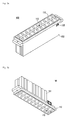
- Figs. 1a and 1b are a plan perspective view and a bottom perspective view respectively which show a configuration of a lighting apparatus according to an embodiment.
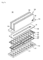
- Figs. 2a and 2b are bottom perspective views showing a configuration of a lighting module constituting the lighting apparatus according to the embodiment.
- Figs. 3a and 3b are exploded perspective views for describing in detail configurations of the lighting modules shown in Figs. 2a and 2b respectively.
- Fig. 3c is a perspective view showing a configuration of a heat sink of the lighting apparatus according to the embodiment.
- the lighting apparatus may be formed to include a lighting module 100, a frame 200 receiving the lighting module 100, and a power supplier 300 which is formed on one side of the frame 200 and supplies electric power to the lighting module 100.
- the power supplier 300 may be formed in another way.
- the power supplier 300 may be formed on one side of the frame, which is perpendicular to the longitudinal direction of the lighting module 100 among the sides of the frame in such a manner as to be adjacent to all of the lighting modules 100.
- the power supplier 300 may be formed outside the frame 200 and supply electric power through a cable and the like.
- the frame 200 may receive at least one lighting module 100.
- the lighting modules 100 may be arranged separately from each other at a predetermined interval in parallel in the longitudinal direction thereof.
- the rectangular lighting modules 100 as viewed in the plan view may be arranged in parallel with each other at a predetermined interval in the longitudinal direction of the frame.
- the interval between the lighting modules 100 is able to perform the same function as that of an opening portion formed in the lighting module 100 itself. This will be described later.
- the frame 200 may be formed to have a standardized size.
- the frame 200 may be formed in such a manner as to receive a certain number of the standardized lighting modules 100. While the drawings show the frame 200 capable of receiving five lighting modules 100 in all, it is also possible to form the frame 200 capable of receiving another number of the lighting modules 100.
- the lighting module 100 received in the frame 200 may be formed to include a cover 110, a light emitting device module 120, a waterproof body 130, a substrate 140 and a heat sink 150.
- the cover 110 covers and protects the light emitting device module 120.
- the cover 110 may include at least one opening 111 allowing a light source included in the light emitting device module 120 to be exposed outward when the cover 110 is coupled to the light emitting device module 120.
- the opening 111 may be formed corresponding to the shape of the light emitting device module 120 designed to be coupled to the cover 110 and the shape of the light source included in the light emitting device module 120.
- An opening portion 112 may be formed in the cover 110 according to the embodiment.
- the opening portion 112 is able to function as an air flow path when the lighting apparatus outdoors operates.
- the opening portion 112 may be formed in parallel with the longitudinal direction of the cover 110 and pass through the center of the cover110, or may be formed at a different position and in a different direction.
- the cover 110 may be formed of a material having a heat radiating characteristic suitable for radiating heat from the light emitting device module 120.
- the light emitting device module 120 may be formed to include at least one light emitting device.
- the light emitting device functions as a light source of the entire lighting module 100. While the drawings show a bar-type light emitting device module 120, the light emitting device modules 120 having different types may be included.
- the light emitting device included in the light emitting device module 120 that is, the light source is exposed outward through the opening 111 of the cover 110 and emits light.
- the light emitting device module 120 may be generally formed to be received in the cover 110 and it is recommended that the cover 110 should be formed not to cover the opening portion 112.
- the light emitting device included in the cover 110 may be a light emitting diode (LED) or may be other kinds of light emitting devices.
- LED light emitting diode
- the waterproof body 130 formed to have a shape corresponding to the shapes of the cover 110 and the substrate 140 may be interposed.
- the waterproof body 130 may be formed for the purpose of waterproofing the entire lighting module 100 and light emitting device module 120.
- the waterproof body 130 may be formed of a material, for example, rubber, etc., which does not absorb moisture.
- the waterproof body 130 may be formed to have a shape corresponding to the shapes of the cover 110 and the substrate 140. In other words, the entire waterproof body 130 may be formed to have the same shape as the shapes of the cover 110 and the substrate 140 and to have an opening portion 132 which is formed at a position corresponding to those of the opening portions 112 and 142 of the cover 110 and the substrate 140 and has the same shape as the shapes of the opening portions 112 and 142.
- the substrate 140 may be a printed circuit board (PCB) and the like.
- the substrate 140 may have wiring formed therein so as to drive the light emitting device included in the light emitting device module 120.
- the substrate 140 has a shape corresponding to those of the cover 110 and the waterproof body 130. That is, the substrate 140 also have an opening portion 142 which is formed at a position corresponding to those of the opening portions 112 and 132 of the cover 110 and the waterproof body 130 and has the same shape as the shapes of the opening portions 112 and 132.
- the heat sink 150 functions to radiate heat generated from the entire lighting module 100 by the operation of the light emitting device module 120.
- the heat sink 150 may be formed to have the maximal surface area for the sake of heat radiation efficiency.
- the heat sink 150 may be formed to include at least one partition wall 156, which is formed in parallel at a regular interval in the longitudinal direction of the heat sink 150, on a base 154 including an opening portion 152 formed therein corresponding to opening portions of the cover 110, the waterproof body 130 and the substrate 140.
- the at least one partition wall 156 may be constituted by a plurality of poles having a polygonal cross section.
- the heat sink 150 may be formed to include at least one partition wall 156, which is formed in parallel at a regular interval in a direction perpendicular to the longitudinal direction of the heat sink 150, on the base 154 including the opening portion 152 formed therein.
- the heat sink 150 may be formed of a material having an excellent heat radiating characteristic, for example, aluminum and the like.
- the surface of the interval between the partition walls 156 may be formed obliquely at a certain angle perpendicularly to the longitudinal direction of the heat sink 150.
- the surface of the interval may be oblique toward the opening portion 152.
- the partition wall 156 may be formed on the base 154 including a surface inclined at a certain angle toward the opening portion 152.
- inclined surfaces may be formed on both sides of the opening portion 152. The inclined surface functions as a flow path of rainwater staying in the lighting module 100 when it rains. Therefore, the inclined surface allows the rainwater easily to flows out through the opening portion 152.
- the base 154 of the heat sink 150 may be formed obliquely at a predetermined angle perpendicular to the longitudinal direction of the heat sink 150.
- the interval between the lighting modules 100 functions as a flow path of rainwater flowing along the base 154.
- a coupling recess 158 may be formed on sides of both ends of the heat sink 150 according to the embodiment. This intends that when the at least one lighting module 100 is disposed in the frame 200, a coupling member which improves the waterproof characteristics in the coupling of the lighting modules 100 is inserted into the coupling recess 158.
- the coupling recess 158 may be formed to completely pass through the both sides of the heat sink 150 or may be formed to partially pass through the heat sink 150.
- a component formed of a material having excellent moisture-proof characteristics, such as rubber and the like may be inserted into the coupling recess 158 at the time of the coupling of the lighting modules 100.
- the lighting modules 100 are coupled to each other by inserting the coupling member like an O-ring into the coupling recess 158.
- the coupling recess 158 may be formed on both sides of the lighting module 100 or may be formed on any one of both side of the lighting module 100.
- a coupling material is inserted into the coupling recess 158 and is pressed by the side of another lighting module 100, so that the lighting modules 100 are coupled to each other.
- the coupling recess 158 should be formed adjacent to both ends of the heat sink 150 in the longitudinal direction of the heat sink 150 for the purpose of the reliability of the coupling of the lighting modules 100.
- the coupling recess 158 may be formed in another position of the heat sink 150.
- Components which are necessarily waterproofed for example, wiring lines for driving the light emitting device module 120 may be formed around the coupling recess 158. Thanks to a process of coupling of the lighting modules 100 by inserting the material having excellent waterproof characteristics such as rubber and the like into the coupling recess 158, the components can be protected from moisture.
- the light emitting device module 120 is received in the cover 110.
- the waterproof body 130 and the substrate 140 are sequentially formed on the light emitting device module 120, and then the heat sink 150 is formed.
- the lighting module 100 may be completed.
- the opening portions 112, 132, 142 and 152 of the cover 110, the waterproof body 130, the substrate 140 and the heat sink 150 are disposed to be aligned with each other, so that a space is formed within the lighting module 100.
- the space functions as an air flow path when the lighting apparatus according to the embodiment is provided outdoors. Accordingly, the heat radiating characteristic of the entire lighting apparatus can be improved.
- the lighting module 100 may be coupled to the frame 200 by a fastening member 400 passing through both ends of the heat sink 150 and a predetermined point of the frame 200.
- the fastening member 400 may have a screw shape passing through a predetermined point of the frame 200 by rotating and inserting or may have a nail shape passing through a predetermined point of the frame 200 by being forcibly inserted by an external force.
- the fastening member 400 may be adhered and fixed by passing through a predetermined point of the frame 200.
- the lighting modules 100 When the lighting module 100 is received in the frame 200, the lighting modules 100 may be, as described above, coupled to each other by the coupling member (not shown) inserted into the coupling member.
- the coupling member may be formed of a material having excellent waterproof characteristics, such as rubber and the like.
- the O-ring may function as the coupling member. Since the coupling member is elastic, the coupling of the lighting modules 100 becomes loose with the elapse of time, so that the intervals between the lighting modules 100 may be irregular or increased. Therefore, the lighting apparatus according to the embodiment includes a pressing portion 210 at the end of the frame 200.
- the pressing portion 210 includes an insertion portion 212 and a pressing member 214.
- the insertion portion 212 extends from the frame 200 and includes an insertion hole formed therein.
- the pressing member 214 passes through the insertion hole of the insertion portion 212.
- the pressing member 214 may be formed of a component which is fixed passing through the insertion hole.
- the pressing member 214 may have a screw shape which passes through the insertion portion 212 by rotating and inserting or may have a nail shape which passes through the insertion portion 212.
- the insertion portion 212 is not formed before the pressing member 214 is inserted into the insertion portion 212, but is formed simultaneously when the pressing member 214 is inserted into the pressing portion 210 by an external force.
- the pressing member 214 may be also adhered and fixed to the insertion portion 212.
- a packing portion may be further formed inside the insertion portion 212 in order to more securely fix the pressing member 214.
- the packing portion may be formed of a material such as rubber or leather and the like.
- a plurality of the pressing portions 210 may be formed on the side of the frame 200, which is parallel with the longitudinal direction of the lighting module 100. Accordingly, the pressing member 214 passing through the insertion hole of the insertion portion 212 may be formed in a direction perpendicular to the longitudinal direction of the lighting module 100, that is, in parallel with the direction in which the coupling recess 158 of the heat sink 150 is formed. The pressing member 214 presses the side of the lighting module 100 which is the closest to the pressing portion 210.
- the pressing member 214 presses the side of the heat sink 150 of the lighting module 100 and causes the lighting modules 100 to be more securely coupled to each other by the coupling member like the O-ring. As a result, the moisture-proof characteristics of the entire lighting apparatus can be improved.
- the pressing portion 210 is formed only on one side of the sides of the frame 200, the pressing portion 210 may be also formed on the opposite side as well.
- the lighting apparatus since one or more lighting modules 100 are coupled to each other by the O-ring and the lighting modules 100 are more securely coupled to each other by the pressing portion 210, the lighting apparatus has excellent moisture-proof characteristics and can be used outdoors.
- one or more lighting modules 100 may be formed separately from each other at a predetermined interval in parallel with each other.
- the interval between the lighting modules is able to perform the same function as that of the space formed in the lighting module 100, that is, the space formed by aligning the opening portions 112, 132, 142 and 152 of the cover 110, the waterproof body 130, the substrate 140 and the heat sink 150.
- the lighting apparatus according to the embodiment may be used outdoors.
- an air flow path is formed by a space formed in the lighting module 100 and a predetermined space formed between the lighting modules 100. Accordingly, the heat radiating characteristic of the entire lighting apparatus can be improved.
- the lighting apparatus may have excellent waterproof characteristics and a heat radiating characteristic improved due to the flow of the rainwater.
- Fig. 4a is a plan perspective view showing a configuration of a lighting apparatus according to a second embodiment.
- Fig. 4b is a bottom perspective view showing a configuration of the lighting apparatus according to the second embodiment.
- the necessary maximum power output of the lighting apparatus may be changed according to a place or environment in which the lighting apparatus is installed. For example, when the electric capacity of one lighting module 100 is 20 W, the required electric power of the entire lighting apparatus may be 40 W, 60W or 80 W and the like.
- a dummy area "D" is formed in the frame 200 in order to cope with electric power requirements which are changed depending on situations.
- the maximum number of the lighting modules 100 arranged in the frame 200 is "n”
- the smaller number than "n” of the lighting modules 100 are arranged if necessary, and the rest of the area of the frame 200 may be filled with the dummy area "D".
- the dummy area "D” does not include the lighting module 100 and only fills the space of the frame.
- the dummy area "D” may be formed as an empty space.
- a sub-frame 220 having a shape corresponding to that of the cover 110 of the lighting module 100 may be arranged instead of the lighting module 100.
- a heat sink may be further disposed on or under the sub-frame 220 so as to radiate heat generated from the light emitting device module 120 of the lighting module 100.
- the heat sink may be formed to have the same shape as that of the heat sink 150 of the lighting module 100.
- the sub-frame 220 may be formed to have exactly the same shape as that of the cover 110 or may be formed to have the shape of the cover 110 without the opening 111.
- both ends of the sub-frame 220 may include a fastening recess 222 allowing the sub-frame 220 to couple to the frame 200.
- the sub-frame 220 and the frame 200 may be coupled to each other by a fastening member passing through the fastening recess 222. It is recommended that the dummy area "D" should be located as far as possible from the power supplier 300 for the sake of efficiency of electric power supply.
- the frame 200 capable of receiving the number required for necessary maximum power output of the lighting modules 100 is manufactured to share the use of the frame.
- a certain area of the frame 200 is assigned as the dummy area "D", so that it is possible to implement a lighting apparatus which gives a required power output.
- parts of the lighting apparatus can be shared for use.
- Fig. 5a is a plan perspective view showing a configuration of a lighting apparatus according to a third embodiment.
- Fig. 5b is a bottom perspective view showing a configuration of the lighting apparatus according to the third embodiment. Descriptions of the same components as those of the first and the second embodiments will be omitted.
- the cover 110 may be formed corresponding to the shape of the light emitting device module 120 designed to be coupled to the cover 110 and the shape of the light source included in the light emitting device module 120.
- the opening 111 may be also formed to have a square shape corresponding to that of the light emitting device module 120.
- a connector “C” may be formed in one outer end of the cover 110 according to the third embodiment in order to allow the cover 110 to be electrically connected to the power supplier 300.
- the connector “C” may be formed to have a depression into which the terminal of the power supplier 300 is inserted or may be formed to have another shape.
- the connector “C” may be formed of a conductive material for the purpose of electrical connection between the light emitting device module 120 and the substrate 140.
- the inner wall of the depression into which the terminal of the power supplier 300 is inserted may be formed of a conductive material.
- the light emitting device module 120 received in the cover 110 may include one or more light emitting devices, for example, four light emitting devices arranged in the form of a matrix.
- the lighting module 100 may be formed on the frame 200.
- the lighting module 100 may be directly connected with the power supplier 300 by the connector "C" formed in one end of the lighting module 100.
- the terminal of the power supplier 300 is inserted into the depression of the connector "C" formed in one outer end of the cover 110 of the lighting module 100, so that the lighting module 100 is electrically connected to the power supplier 300. Accordingly, electric power from the power supplier 300 may be directly supplied to the lighting module100.
- the power supplier 300 may be disposed adjacent to one ends of all of the lighting modules 100 in order to be directly connected to all of the lighting modules 100. Accordingly, all of the lighting modules 100 arranged on the frame 200 can be directly connected to the power supplier 300 without separate component such as a cable and the like.
- the lighting module 100 may be coupled to the frame 200 in a pressing manner. That is, the lighting module 100 can be fixed by pressing one end of the lighting module 100, which is not connected to the power supplier 300 among both ends of the lighting module 100.
- an insertion portion 230 is formed on one edge of the frame 200, that is to say, one side of the frame 200, which is adjacent to one end of the lighting module 100, which is not connected to the power supplier 300 among both ends of the lighting module 100.
- a pressing member 240 is connected to the insertion portion 230. The pressing member 240 presses the one end of the lighting module 100, fixing the lighting module.
- the lighting module 100 is not only directly connected to the power supplier 300 but is pressed by the pressing member 240, so that both ends of the lighting module 100 are pressed. Accordingly, the lighting module 100 can be securely coupled.
- Fig. 5c is an exploded perspective view for describing a configuration of the lighting module 100 according to the third embodiment.
- the lighting module 100 received in the frame 200 may include the cover 110, the light emitting device module 120, the waterproof body 130, the substrate 140 and the heat sink 150.
- the cover 110 protects the light emitting device module 120.
- the cover 110 may include at least one opening 111 allowing a light source included in the light emitting device module 120 to be exposed outward.
- the opening 111 may be formed corresponding to the shape of the light emitting device module 120 and the shape of the light source included in the light emitting device module 120.
- the opening 111 may have a square shape corresponding to that of the light emitting device module 120.
- the connector "C" may be formed in one outer end of the cover 110 in order to allow the cover 110 to be electrically connected to the power supplier 300.
- the waterproof body 130 may be disposed between the light emitting device module 120 and the cover 110.
- the waterproof body 130 may include an opening 131 formed at a position corresponding to that of the opening 111 of the cover 110.
- the waterproof body 130 may be formed of an insulation material such as rubber and the like for the sake of waterproof characteristics and the like.
- the light emitting device module 120 may include a plurality of the light emitting devices (for example, more than four) which are arranged in the form of a matrix.
- the light emitting device included in the light emitting device module 120 may be exposed outward through the opening 111 and emit light.
- Wiring lines for driving the light emitting device of the light emitting device module 120 may be formed on the substrate 140.
- the wiring lines formed in the substrate 140 may be electrically connected to the connector "C" of the cover 110.
- the cover 110 is capable of receiving an insulation layer 130, the light emitting device module 120 and the substrate 140.
- the heat sink 150 may be formed on the cover 110.
- the heat sink 150 functions to radiate heat generated from the entire lighting module 100 by the operation of the light emitting device module 120.
- the heat sink 150 may be formed to include at least one partition wall 156 on the base 154.
- the one or more partition walls 156 are formed in parallel at a regular interval in the longitudinal direction of the heat sink 150.
Landscapes
- Engineering & Computer Science (AREA)
- General Engineering & Computer Science (AREA)
- Physics & Mathematics (AREA)
- Microelectronics & Electronic Packaging (AREA)
- Optics & Photonics (AREA)
- Arrangement Of Elements, Cooling, Sealing, Or The Like Of Lighting Devices (AREA)
- Non-Portable Lighting Devices Or Systems Thereof (AREA)
Abstract

Description
- This application claims priority from Korean Application No.
10-2010-0117191, filed on November 24, 2010 10-2010-0118926, filed on November 26, 2010 10-2010-0118927, filed on November 26, 2010 10-2010-0118928, filed on November 26, 2010 10-2010-0118929, filed on November 26, 2010 - Embodiments may relate to a lighting module and a lighting apparatus comprising the same.
- In general, an electric bulb or a fluorescent lamp is commonly used as an indoor or outdoor lighting lamp. However, the electric bulb or the fluorescent lamp has a short life span, so that it should be frequently changed. Moreover, a conventional fluorescent lamp is degraded due to elapse of time for its use. As a result, it is often that its illuminance is gradually decreased.
- In order to overcome such problems, various types of lighting apparatuses are now being developed by using a light emitting device (hereinafter, referred to as LED). The LED is easy to control and has a rapid response speed, high electro-optic conversion efficiency, a long life span, low power consumption and high luminance. The LED is also used to create emotional lighting.
- Recently, efforts are being made to provide outdoors and use the lighting apparatus. Therefore, there is a necessity of an optimized design of a heat radiating configuration or a coupling configuration of the lighting apparatus, which is suitable to outdoors use the lighting apparatus.
- One embodiment is a lighting module. The lighting module includes: a light emitting device module including at least one light emitting device; and a heat sink radiating heat generated from the light emitting device module and including at least one partition wall formed on a base.
- At least one inclined surface at a predetermined angle may be formed on at least a portion of the top surface of the base.
- A first opening portion may be formed at a predetermined point of the base. The at least one inclined surface may be inclined toward the opening portion.
- The lighting module may further include a substrate disposed between the light emitting device module and the heat sink; and a cover in which the light emitting device module is disposed. At least two of the heat sink, the substrate and the cover may include a second opening portion corresponding to the first opening portion.
- The lighting module may further include a waterproof body disposed between the light emitting device module and the substrate. The waterproof body may include a third opening portion corresponding to the first opening portion.
- The at least one partition wall may be formed in a first direction parallel with the longitudinal direction of the base or in a second direction perpendicular to the first direction.
- The lighting module may further include a cover accommodating the light emitting device module disposed therein and including a connector which is formed in one side of the cover and is connected to a power supplier for driving the light emitting device module.
- The connector may include a depression allowing the terminal of the power supplier to be directly inserted into the connector.
- The partition wall may be constituted by a plurality of poles having a polygonal cross section.
- The lighting module may include: a cover accommodating the light emitting device module and including a first opening exposing a light emitting device disposed on one side of the light emitting device module; a waterproof body being disposed between the cover and the light emitting device module and including a second opening corresponding to the first opening of the cover; and a substrate being disposed on the other side of the light emitting device module and including wiring lines for driving the light emitting device.
- Another embodiment is a lighting apparatus. The lighting apparatus includes: one or more lighting modules having the aforementioned features; and a frame in which the one or more lighting modules are disposed adjacent to each other.
- The lighting apparatus may further include a pressing portion at one side of the frame, which supports one side of a lighting module disposed closest to the one side of the frame among the one or more lighting modules.
- The lighting apparatus may further include a coupling member supporting between the lighting modules.
- One side of the heat sink included in the lighting module may include a coupling recess into which the coupling member is inserted.
- The one or more lighting modules may be disposed in some areas of the frame. A dummy area including no lighting module may be formed in the rest of the area of the frame.
- A sub-frame covering at least a portion of the rest of the area of the frame may be disposed in the dummy area.
- The one or more lighting modules may be sequentially arranged in a farther direction from the power supplier. The dummy area may be disposed as far as possible from the power supplier.
- Arrangements and embodiments may be described in detail with reference to the following drawings in which like reference numerals refer to like elements and wherein:
-
Fig. 1a is a plan perspective view showing a configuration of a lighting apparatus according to a first embodiment; -
Fig. 1b is a bottom perspective view showing a configuration of the lighting apparatus according to the first embodiment; -
Figs. 2a and 2b are bottom perspective views showing a configuration of a lighting module according to the first embodiment; -
Figs. 3a and3b are exploded perspective views for describing in detail configurations of the lighting modules shown inFigs. 2a and 2b respectively; -
Fig. 3c is a perspective view showing a configuration of a heat sink included in the lighting module according to the embodiment; -
Fig. 4a is a plan perspective view showing a configuration of a lighting apparatus according to a second embodiment; -
Fig. 4b is a bottom perspective view showing a configuration of the lighting apparatus according to the second embodiment; -
Fig. 5a is a plan perspective view showing a configuration of a lighting apparatus according to a third embodiment; -
Fig. 5b is a bottom perspective view showing a configuration of the lighting apparatus according to the third embodiment; -
Fig. 5c is an exploded perspective view of a lighting module included in the lighting apparatus according to the third embodiment. - A thickness or a size of each layer may be magnified, omitted or schematically shown for the purpose of convenience and clearness of description. The size of each component may not necessarily mean its actual size.
- It should be understood that when an element is referred to as being 'on' or "under" another element, it may be directly on/under the element, and/or one or more intervening elements may also be present. When an element is referred to as being 'on' or 'under', 'under the element' as well as 'on the element' may be included based on the element.
- An embodiment may be described in detail with reference to the accompanying drawings.
-
Figs. 1a and1b are a plan perspective view and a bottom perspective view respectively which show a configuration of a lighting apparatus according to an embodiment.Figs. 2a and 2b are bottom perspective views showing a configuration of a lighting module constituting the lighting apparatus according to the embodiment.Figs. 3a and3b are exploded perspective views for describing in detail configurations of the lighting modules shown inFigs. 2a and 2b respectively.Fig. 3c is a perspective view showing a configuration of a heat sink of the lighting apparatus according to the embodiment. - The lighting apparatus according to the embodiment may be formed to include a
lighting module 100, aframe 200 receiving thelighting module 100, and apower supplier 300 which is formed on one side of theframe 200 and supplies electric power to thelighting module 100. Although the drawings show that thepower supplier 300 is formed adjacent to any onelighting module 100 of a plurality of the lighting modules, thepower supplier 300 may be formed in another way. For example, thepower supplier 300 may be formed on one side of the frame, which is perpendicular to the longitudinal direction of thelighting module 100 among the sides of the frame in such a manner as to be adjacent to all of thelighting modules 100. Also, thepower supplier 300 may be formed outside theframe 200 and supply electric power through a cable and the like. - The
frame 200 may receive at least onelighting module 100. Thelighting modules 100 may be arranged separately from each other at a predetermined interval in parallel in the longitudinal direction thereof. For example, as shown in the drawings, therectangular lighting modules 100 as viewed in the plan view may be arranged in parallel with each other at a predetermined interval in the longitudinal direction of the frame. The interval between thelighting modules 100 is able to perform the same function as that of an opening portion formed in thelighting module 100 itself. This will be described later. Theframe 200 may be formed to have a standardized size. For example, theframe 200 may be formed in such a manner as to receive a certain number of thestandardized lighting modules 100. While the drawings show theframe 200 capable of receiving fivelighting modules 100 in all, it is also possible to form theframe 200 capable of receiving another number of thelighting modules 100. - The
lighting module 100 received in theframe 200 may be formed to include acover 110, a light emittingdevice module 120, awaterproof body 130, asubstrate 140 and aheat sink 150. - The
cover 110 covers and protects the light emittingdevice module 120. Thecover 110 may include at least oneopening 111 allowing a light source included in the light emittingdevice module 120 to be exposed outward when thecover 110 is coupled to the light emittingdevice module 120. Theopening 111 may be formed corresponding to the shape of the light emittingdevice module 120 designed to be coupled to thecover 110 and the shape of the light source included in the light emittingdevice module 120. Anopening portion 112 may be formed in thecover 110 according to the embodiment. Theopening portion 112 is able to function as an air flow path when the lighting apparatus outdoors operates. Theopening portion 112 may be formed in parallel with the longitudinal direction of thecover 110 and pass through the center of the cover110, or may be formed at a different position and in a different direction. Thecover 110 may be formed of a material having a heat radiating characteristic suitable for radiating heat from the light emittingdevice module 120. - The light emitting
device module 120 may be formed to include at least one light emitting device. The light emitting device functions as a light source of theentire lighting module 100. While the drawings show a bar-type light emittingdevice module 120, the light emittingdevice modules 120 having different types may be included. The light emitting device included in the light emittingdevice module 120, that is, the light source is exposed outward through theopening 111 of thecover 110 and emits light. The light emittingdevice module 120 may be generally formed to be received in thecover 110 and it is recommended that thecover 110 should be formed not to cover theopening portion 112. The light emitting device included in thecover 110 may be a light emitting diode (LED) or may be other kinds of light emitting devices. - The
waterproof body 130 formed to have a shape corresponding to the shapes of thecover 110 and thesubstrate 140 may be interposed. Thewaterproof body 130 may be formed for the purpose of waterproofing theentire lighting module 100 and light emittingdevice module 120. Thewaterproof body 130 may be formed of a material, for example, rubber, etc., which does not absorb moisture. Thewaterproof body 130 may be formed to have a shape corresponding to the shapes of thecover 110 and thesubstrate 140. In other words, the entirewaterproof body 130 may be formed to have the same shape as the shapes of thecover 110 and thesubstrate 140 and to have anopening portion 132 which is formed at a position corresponding to those of the openingportions cover 110 and thesubstrate 140 and has the same shape as the shapes of the openingportions - The
substrate 140 may be a printed circuit board (PCB) and the like. Thesubstrate 140 may have wiring formed therein so as to drive the light emitting device included in the light emittingdevice module 120. As described above, thesubstrate 140 has a shape corresponding to those of thecover 110 and thewaterproof body 130. That is, thesubstrate 140 also have anopening portion 142 which is formed at a position corresponding to those of the openingportions cover 110 and thewaterproof body 130 and has the same shape as the shapes of the openingportions - The
heat sink 150 functions to radiate heat generated from theentire lighting module 100 by the operation of the light emittingdevice module 120. Theheat sink 150 may be formed to have the maximal surface area for the sake of heat radiation efficiency. For example, as shown inFig. 3a , theheat sink 150 may be formed to include at least onepartition wall 156, which is formed in parallel at a regular interval in the longitudinal direction of theheat sink 150, on a base 154 including anopening portion 152 formed therein corresponding to opening portions of thecover 110, thewaterproof body 130 and thesubstrate 140. The at least onepartition wall 156 may be constituted by a plurality of poles having a polygonal cross section. - Also, as shown in
Fig. 3b , theheat sink 150 may be formed to include at least onepartition wall 156, which is formed in parallel at a regular interval in a direction perpendicular to the longitudinal direction of theheat sink 150, on the base 154 including theopening portion 152 formed therein. Theheat sink 150 may be formed of a material having an excellent heat radiating characteristic, for example, aluminum and the like. - As shown in
Fig. 3c , the surface of the interval between thepartition walls 156 may be formed obliquely at a certain angle perpendicularly to the longitudinal direction of theheat sink 150. For example, the surface of the interval may be oblique toward theopening portion 152. That is, thepartition wall 156 may be formed on the base 154 including a surface inclined at a certain angle toward theopening portion 152. As shown inFig. 3c , when theopening portion 152 is formed in the center of the base 154 in parallel with the longitudinal direction of thebase 154, inclined surfaces may be formed on both sides of theopening portion 152. The inclined surface functions as a flow path of rainwater staying in thelighting module 100 when it rains. Therefore, the inclined surface allows the rainwater easily to flows out through theopening portion 152. - Meanwhile, when the
cover 110, thewaterproof body 130, thesubstrate 140 and theheat sink 150 do not include the openingportions base 154 of theheat sink 150 may be formed obliquely at a predetermined angle perpendicular to the longitudinal direction of theheat sink 150. In this case, when thelighting module 100 is received in theframe 200, the interval between thelighting modules 100 functions as a flow path of rainwater flowing along thebase 154. - A
coupling recess 158 may be formed on sides of both ends of theheat sink 150 according to the embodiment. This intends that when the at least onelighting module 100 is disposed in theframe 200, a coupling member which improves the waterproof characteristics in the coupling of thelighting modules 100 is inserted into thecoupling recess 158. Thecoupling recess 158 may be formed to completely pass through the both sides of theheat sink 150 or may be formed to partially pass through theheat sink 150. A component formed of a material having excellent moisture-proof characteristics, such as rubber and the like may be inserted into thecoupling recess 158 at the time of the coupling of thelighting modules 100. For example, thelighting modules 100 are coupled to each other by inserting the coupling member like an O-ring into thecoupling recess 158. Thecoupling recess 158 may be formed on both sides of thelighting module 100 or may be formed on any one of both side of thelighting module 100. A coupling material is inserted into thecoupling recess 158 and is pressed by the side of anotherlighting module 100, so that thelighting modules 100 are coupled to each other. It is desirable that thecoupling recess 158 should be formed adjacent to both ends of theheat sink 150 in the longitudinal direction of theheat sink 150 for the purpose of the reliability of the coupling of thelighting modules 100. However, thecoupling recess 158 may be formed in another position of theheat sink 150. Components which are necessarily waterproofed, for example, wiring lines for driving the light emittingdevice module 120 may be formed around thecoupling recess 158. Thanks to a process of coupling of thelighting modules 100 by inserting the material having excellent waterproof characteristics such as rubber and the like into thecoupling recess 158, the components can be protected from moisture. - The light emitting
device module 120 is received in thecover 110. Thewaterproof body 130 and thesubstrate 140 are sequentially formed on the light emittingdevice module 120, and then theheat sink 150 is formed. Thus, thelighting module 100 may be completed. In thelighting module 100, the openingportions cover 110, thewaterproof body 130, thesubstrate 140 and theheat sink 150 are disposed to be aligned with each other, so that a space is formed within thelighting module 100. The space functions as an air flow path when the lighting apparatus according to the embodiment is provided outdoors. Accordingly, the heat radiating characteristic of the entire lighting apparatus can be improved. - The
lighting module 100 may be coupled to theframe 200 by afastening member 400 passing through both ends of theheat sink 150 and a predetermined point of theframe 200. Thefastening member 400 may have a screw shape passing through a predetermined point of theframe 200 by rotating and inserting or may have a nail shape passing through a predetermined point of theframe 200 by being forcibly inserted by an external force. Thefastening member 400 may be adhered and fixed by passing through a predetermined point of theframe 200. - When the
lighting module 100 is received in theframe 200, thelighting modules 100 may be, as described above, coupled to each other by the coupling member (not shown) inserted into the coupling member. The coupling member may be formed of a material having excellent waterproof characteristics, such as rubber and the like. For example, the O-ring may function as the coupling member. Since the coupling member is elastic, the coupling of thelighting modules 100 becomes loose with the elapse of time, so that the intervals between thelighting modules 100 may be irregular or increased. Therefore, the lighting apparatus according to the embodiment includes apressing portion 210 at the end of theframe 200. Thepressing portion 210 includes aninsertion portion 212 and apressing member 214. Theinsertion portion 212 extends from theframe 200 and includes an insertion hole formed therein. The pressingmember 214 passes through the insertion hole of theinsertion portion 212. The pressingmember 214 may be formed of a component which is fixed passing through the insertion hole. According to the embodiment, the pressingmember 214 may have a screw shape which passes through theinsertion portion 212 by rotating and inserting or may have a nail shape which passes through theinsertion portion 212. When thepressing member 214 has the nail shape, theinsertion portion 212 is not formed before thepressing member 214 is inserted into theinsertion portion 212, but is formed simultaneously when thepressing member 214 is inserted into thepressing portion 210 by an external force. The pressingmember 214 may be also adhered and fixed to theinsertion portion 212. A packing portion may be further formed inside theinsertion portion 212 in order to more securely fix thepressing member 214. The packing portion may be formed of a material such as rubber or leather and the like. - When one or
more lighting modules 100 are arranged in a certain direction with respect to theframe 200, a plurality of thepressing portions 210 may be formed on the side of theframe 200, which is parallel with the longitudinal direction of thelighting module 100. Accordingly, the pressingmember 214 passing through the insertion hole of theinsertion portion 212 may be formed in a direction perpendicular to the longitudinal direction of thelighting module 100, that is, in parallel with the direction in which thecoupling recess 158 of theheat sink 150 is formed. The pressingmember 214 presses the side of thelighting module 100 which is the closest to thepressing portion 210. Specifically, the pressingmember 214 presses the side of theheat sink 150 of thelighting module 100 and causes thelighting modules 100 to be more securely coupled to each other by the coupling member like the O-ring. As a result, the moisture-proof characteristics of the entire lighting apparatus can be improved. - While the drawings show that the
pressing portion 210 is formed only on one side of the sides of theframe 200, thepressing portion 210 may be also formed on the opposite side as well. - In the lighting apparatus according to the embodiment, since one or
more lighting modules 100 are coupled to each other by the O-ring and thelighting modules 100 are more securely coupled to each other by thepressing portion 210, the lighting apparatus has excellent moisture-proof characteristics and can be used outdoors. - Meanwhile, one or
more lighting modules 100 may be formed separately from each other at a predetermined interval in parallel with each other. The interval between the lighting modules is able to perform the same function as that of the space formed in thelighting module 100, that is, the space formed by aligning the openingportions cover 110, thewaterproof body 130, thesubstrate 140 and theheat sink 150. - The lighting apparatus according to the embodiment may be used outdoors. For example, when the lighting apparatus is used as a street lamp, an air flow path is formed by a space formed in the
lighting module 100 and a predetermined space formed between thelighting modules 100. Accordingly, the heat radiating characteristic of the entire lighting apparatus can be improved. - Besides, since the spaces are able to function as a flow path of rainwater, the lighting apparatus may have excellent waterproof characteristics and a heat radiating characteristic improved due to the flow of the rainwater.
-
Fig. 4a is a plan perspective view showing a configuration of a lighting apparatus according to a second embodiment.Fig. 4b is a bottom perspective view showing a configuration of the lighting apparatus according to the second embodiment. - The necessary maximum power output of the lighting apparatus may be changed according to a place or environment in which the lighting apparatus is installed. For example, when the electric capacity of one
lighting module 100 is 20 W, the required electric power of the entire lighting apparatus may be 40 W, 60W or 80 W and the like. - In the second embodiment, a dummy area "D" is formed in the
frame 200 in order to cope with electric power requirements which are changed depending on situations. In other words, when the maximum number of thelighting modules 100 arranged in theframe 200 is "n", the smaller number than "n" of thelighting modules 100 are arranged if necessary, and the rest of the area of theframe 200 may be filled with the dummy area "D". The dummy area "D" does not include thelighting module 100 and only fills the space of the frame. The dummy area "D" may be formed as an empty space. Otherwise, as shown inFigs. 4a and 4b , asub-frame 220 having a shape corresponding to that of thecover 110 of thelighting module 100 may be arranged instead of thelighting module 100. Also, though not shown in the drawings, a heat sink may be further disposed on or under thesub-frame 220 so as to radiate heat generated from the light emittingdevice module 120 of thelighting module 100. The heat sink may be formed to have the same shape as that of theheat sink 150 of thelighting module 100. Thesub-frame 220 may be formed to have exactly the same shape as that of thecover 110 or may be formed to have the shape of thecover 110 without theopening 111. Further, both ends of thesub-frame 220 may include afastening recess 222 allowing thesub-frame 220 to couple to theframe 200. Thesub-frame 220 and theframe 200 may be coupled to each other by a fastening member passing through thefastening recess 222. It is recommended that the dummy area "D" should be located as far as possible from thepower supplier 300 for the sake of efficiency of electric power supply. - According to the embodiment, the
frame 200 capable of receiving the number required for necessary maximum power output of thelighting modules 100 is manufactured to share the use of the frame. When power output less than the maximum power output is required, a certain area of theframe 200 is assigned as the dummy area "D", so that it is possible to implement a lighting apparatus which gives a required power output. As a result, parts of the lighting apparatus can be shared for use. -
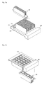
Fig. 5a is a plan perspective view showing a configuration of a lighting apparatus according to a third embodiment.Fig. 5b is a bottom perspective view showing a configuration of the lighting apparatus according to the third embodiment. Descriptions of the same components as those of the first and the second embodiments will be omitted. - The
cover 110 shown inFigs. 5a and 5b , thecover 110 may be formed corresponding to the shape of the light emittingdevice module 120 designed to be coupled to thecover 110 and the shape of the light source included in the light emittingdevice module 120. For example, when the light emittingdevice module 120 is formed to have a square shape having light emitting devices arranged in the form of a matrix, theopening 111 may be also formed to have a square shape corresponding to that of the light emittingdevice module 120. - A connector "C" may be formed in one outer end of the
cover 110 according to the third embodiment in order to allow thecover 110 to be electrically connected to thepower supplier 300. As shown in the drawing, the connector "C" may be formed to have a depression into which the terminal of thepower supplier 300 is inserted or may be formed to have another shape. The connector "C" may be formed of a conductive material for the purpose of electrical connection between the light emittingdevice module 120 and thesubstrate 140. For example, the inner wall of the depression into which the terminal of thepower supplier 300 is inserted may be formed of a conductive material. - The light emitting
device module 120 received in thecover 110 may include one or more light emitting devices, for example, four light emitting devices arranged in the form of a matrix. - The
lighting module 100 may be formed on theframe 200. Thelighting module 100 may be directly connected with thepower supplier 300 by the connector "C" formed in one end of thelighting module 100. For example, the terminal of thepower supplier 300 is inserted into the depression of the connector "C" formed in one outer end of thecover 110 of thelighting module 100, so that thelighting module 100 is electrically connected to thepower supplier 300. Accordingly, electric power from thepower supplier 300 may be directly supplied to the lighting module100. - When the
lighting module 100 is arranged in parallel with each other on theframe 200, thepower supplier 300 may be disposed adjacent to one ends of all of thelighting modules 100 in order to be directly connected to all of thelighting modules 100. Accordingly, all of thelighting modules 100 arranged on theframe 200 can be directly connected to thepower supplier 300 without separate component such as a cable and the like. - The
lighting module 100 may be coupled to theframe 200 in a pressing manner. That is, thelighting module 100 can be fixed by pressing one end of thelighting module 100, which is not connected to thepower supplier 300 among both ends of thelighting module 100. Specifically, aninsertion portion 230 is formed on one edge of theframe 200, that is to say, one side of theframe 200, which is adjacent to one end of thelighting module 100, which is not connected to thepower supplier 300 among both ends of thelighting module 100. Apressing member 240 is connected to theinsertion portion 230. The pressingmember 240 presses the one end of thelighting module 100, fixing the lighting module. - The
lighting module 100 is not only directly connected to thepower supplier 300 but is pressed by the pressingmember 240, so that both ends of thelighting module 100 are pressed. Accordingly, thelighting module 100 can be securely coupled. -
Fig. 5c is an exploded perspective view for describing a configuration of thelighting module 100 according to the third embodiment. - Referring to
Fig. 5c , thelighting module 100 received in theframe 200 may include thecover 110, the light emittingdevice module 120, thewaterproof body 130, thesubstrate 140 and theheat sink 150. - The
cover 110 protects the light emittingdevice module 120. Thecover 110 may include at least oneopening 111 allowing a light source included in the light emittingdevice module 120 to be exposed outward. For example, theopening 111 may be formed corresponding to the shape of the light emittingdevice module 120 and the shape of the light source included in the light emittingdevice module 120. For example, when the light emittingdevice module 120 has, as shown inFig. 5c , a square shape having light emitting devices arranged in the form of a matrix, theopening 111 may have a square shape corresponding to that of the light emittingdevice module 120. - The connector "C" may be formed in one outer end of the
cover 110 in order to allow thecover 110 to be electrically connected to thepower supplier 300. - The
waterproof body 130 may be disposed between the light emittingdevice module 120 and thecover 110. Thewaterproof body 130 may include anopening 131 formed at a position corresponding to that of theopening 111 of thecover 110. Thewaterproof body 130 may be formed of an insulation material such as rubber and the like for the sake of waterproof characteristics and the like. - The light emitting
device module 120 may include a plurality of the light emitting devices (for example, more than four) which are arranged in the form of a matrix. The light emitting device included in the light emittingdevice module 120 may be exposed outward through theopening 111 and emit light. - Wiring lines for driving the light emitting device of the light emitting
device module 120 may be formed on thesubstrate 140. The wiring lines formed in thesubstrate 140 may be electrically connected to the connector "C" of thecover 110. - The
cover 110 is capable of receiving aninsulation layer 130, the light emittingdevice module 120 and thesubstrate 140. Theheat sink 150 may be formed on thecover 110. - The
heat sink 150 functions to radiate heat generated from theentire lighting module 100 by the operation of the light emittingdevice module 120. As shown inFig. 5c , theheat sink 150 may be formed to include at least onepartition wall 156 on thebase 154. The one ormore partition walls 156 are formed in parallel at a regular interval in the longitudinal direction of theheat sink 150. - Although embodiments of the present invention were described above, theses are just examples and do not limit the present invention. Further, the present invention may be changed and modified in various ways, without departing from the essential features of the present invention, by those skilled in the art. For example, the components described in detail in the embodiments of the present invention may be modified. Further, differences due to the modification and application should be construed as being included in the scope and spirit of the present invention, which is described in the accompanying claims.
Claims (15)
- A lighting module comprising:a light emitting device module including at least one light emitting device; anda heat sink radiating heat generated from the light emitting device module and including at least one partition wall formed on a base.
- The lighting module of claim 1, wherein at least one inclined surface at a predetermined angle is formed on at least a portion of the top surface of the base.
- The lighting module of claim 2, wherein a first opening portion is formed at a predetermined area of the base, and wherein the at least one inclined surface is inclined toward the opening portion.
- The lighting module of claim 3, further comprising a substrate disposed between the light emitting device module and the heat sink; and a cover in which the light emitting device module is disposed, wherein at least two of the heat sink, the substrate and the cover include a second opening portion corresponding to the first opening portion.
- The lighting module of claim 4, further comprising a waterproof body disposed between the light emitting device module and the substrate, wherein the waterproof body includes a third opening portion corresponding to the first opening portion.
- The lighting module of any one of claims 1 to 5, wherein the at least one partition wall is formed in a first direction parallel with the longitudinal direction of the base or in a second direction perpendicular to the first direction.
- The lighting module of any one of claims 1 to 3, further comprising a cover accommodating the light emitting device module disposed therein and including a connector which is formed in one side of the cover and is connected to a power supplier for driving the light emitting device module, the connector comprising a depression allowing the terminal of the power supplier to be directly inserted into the connector.
- The lighting module of any one of claims 1 to 5, wherein the partition wall is constituted by a plurality of poles having a polygonal cross section.
- A lighting apparatus comprising:one or more lighting modules as claimed in claim 1; anda frame in which the one or more lighting modules are disposed adjacent to each other.
- The lighting apparatus of claim 9, further comprising a pressing portion at one side of the frame, which supports one side of a lighting module disposed closest to the one side of the frame among the one or more lighting modules.
- The lighting apparatus of claim 10, further comprising a coupling member supporting between the lighting modules.
- The lighting apparatus of claim 11, wherein one side of the heat sink comprises a coupling recess into which the coupling member is inserted.
- The lighting apparatus of claim 9, wherein the one or more lighting modules are disposed in some areas of the frame, and wherein a dummy area including no lighting module is formed in the rest of the area of the frame.
- The lighting apparatus of claim 13, wherein a sub-frame covering at least a portion of the rest of the area of the frame is disposed in the dummy area.
- The lighting apparatus of claim 13, wherein the one or more lighting modules are sequentially arranged in a farther direction from the power supplier, and wherein the dummy area is disposed as far as possible from the power supplier.
Applications Claiming Priority (5)
| Application Number | Priority Date | Filing Date | Title |
|---|---|---|---|
| KR1020100117191A KR101797487B1 (en) | 2010-11-24 | 2010-11-24 | Lighting module and lighting apparatus comprising the same |
| KR1020100118928A KR101861149B1 (en) | 2010-11-26 | 2010-11-26 | Lighting apparatus |
| KR1020100118929A KR101796746B1 (en) | 2010-11-26 | 2010-11-26 | Lighting apparatus |
| KR20100118926A KR20120057265A (en) | 2010-11-26 | 2010-11-26 | Lighting module and lighting apparatus comprising the same |
| KR1020100118927A KR101827714B1 (en) | 2010-11-26 | 2010-11-26 | Lighting module and lighting apparatus comprising the same |
Publications (3)
| Publication Number | Publication Date |
|---|---|
| EP2458261A2 true EP2458261A2 (en) | 2012-05-30 |
| EP2458261A3 EP2458261A3 (en) | 2015-03-04 |
| EP2458261B1 EP2458261B1 (en) | 2018-10-10 |
Family
ID=44925361
Family Applications (1)
| Application Number | Title | Priority Date | Filing Date |
|---|---|---|---|
| EP11187138.0A Not-in-force EP2458261B1 (en) | 2010-11-24 | 2011-10-28 | Lighting module and lighting apparatus comprising the same |
Country Status (3)
| Country | Link |
|---|---|
| US (2) | US8403543B2 (en) |
| EP (1) | EP2458261B1 (en) |
| CN (1) | CN102537721B (en) |
Families Citing this family (8)
| Publication number | Priority date | Publication date | Assignee | Title |
|---|---|---|---|---|
| US9413130B2 (en) * | 2012-12-12 | 2016-08-09 | Cvi Laser, Llc | Optical systems |
| US10114213B2 (en) | 2008-04-04 | 2018-10-30 | Cvi Laser, Llc | Laser systems and optical devices for manipulating laser beams |
| US9097826B2 (en) * | 2011-10-08 | 2015-08-04 | Svv Technology Innovations, Inc. | Collimating illumination systems employing a waveguide |
| KR101701143B1 (en) * | 2014-08-27 | 2017-02-13 | 김종희 | A lamp using led |
| DE102016102279A1 (en) * | 2015-07-15 | 2017-01-19 | Heraeus Noblelight Gmbh | Module-like LED emitter unit and use of the same |
| KR102417439B1 (en) * | 2015-10-20 | 2022-07-07 | 쑤저우 레킨 세미컨덕터 컴퍼니 리미티드 | Illumination apparatus |
| US10612733B2 (en) * | 2017-05-08 | 2020-04-07 | MaxLite, Inc. | Modular light system |
| US11378808B2 (en) | 2018-07-18 | 2022-07-05 | Idex Health & Science Llc | Laser systems and optical devices for laser beam shaping |
Family Cites Families (24)
| Publication number | Priority date | Publication date | Assignee | Title |
|---|---|---|---|---|
| US5036248A (en) * | 1989-03-31 | 1991-07-30 | Ledstar Inc. | Light emitting diode clusters for display signs |
| US5808592A (en) * | 1994-04-28 | 1998-09-15 | Toyoda Gosei Co., Ltd. | Integrated light-emitting diode lamp and method of producing the same |
| MXPA06010839A (en) * | 2004-03-10 | 2007-02-21 | Truck Lite Co | Interior lamp. |
| EP1988329B1 (en) * | 2006-02-20 | 2011-10-26 | Stanley Electric Co., Ltd. | Illumination device |
| US7952262B2 (en) * | 2006-09-30 | 2011-05-31 | Ruud Lighting, Inc. | Modular LED unit incorporating interconnected heat sinks configured to mount and hold adjacent LED modules |
| CN101310567A (en) * | 2006-10-24 | 2008-11-19 | 照宏光电科技股份有限公司 | Lighting apparatus |
| CN201014341Y (en) * | 2007-03-01 | 2008-01-30 | 四川新力光源有限公司 | LED lighting module |
| JP2008226968A (en) * | 2007-03-09 | 2008-09-25 | Rohm Co Ltd | Optical communication module |
| US20090200966A1 (en) * | 2007-05-16 | 2009-08-13 | Amdor, Inc. | Illumination unit with current interrupter component |
| CN201173470Y (en) * | 2008-04-10 | 2008-12-31 | 上海三思电子工程有限公司 | LED lighting lamp modified type component type light source structure |
| KR20100009323A (en) * | 2008-07-18 | 2010-01-27 | 삼성전자주식회사 | Bulb-type light concentrated solar cell module |
| US7952114B2 (en) * | 2008-09-23 | 2011-05-31 | Tyco Electronics Corporation | LED interconnect assembly |
| CN201297542Y (en) * | 2008-11-11 | 2009-08-26 | 东莞乐域塑胶电子制品有限公司 | An LED street lamp |
| JP5304198B2 (en) * | 2008-11-24 | 2013-10-02 | 東芝ライテック株式会社 | lighting equipment |
| US8197115B2 (en) * | 2008-12-30 | 2012-06-12 | Dean Andrew Wilkinson | Luminaire with adjustable light source |
| CN101776254B (en) * | 2009-01-10 | 2012-11-21 | 富准精密工业(深圳)有限公司 | Light emitting diode lamp and photo engine thereof |
| CN201401648Y (en) * | 2009-04-03 | 2010-02-10 | 中盟光电股份有限公司 | Expandable modularized lighting device |
| CH700879A2 (en) * | 2009-04-21 | 2010-10-29 | Quadesign Partner Ag | Outdoor light i.e. street light, has supporting structure connected to cooling surface that emits heat energy to environment, where surface is arranged on side of light and light module emits emission cone to surface during operation |
| CN201487639U (en) * | 2009-08-18 | 2010-05-26 | 林志泽 | Improved structure of light emitting diode lamp tube |
| CN201568818U (en) * | 2009-09-04 | 2010-09-01 | 宁波安迪光电科技有限公司 | LED illumination device |
| KR100956495B1 (en) * | 2009-12-28 | 2010-05-07 | 김세진 | Luminescent tile |
| CN201621501U (en) * | 2010-01-15 | 2010-11-03 | 东莞广宏电子有限公司 | Split-type LED bulb |
| US10585310B2 (en) * | 2010-10-28 | 2020-03-10 | Lg Electronics Inc. | Display device comprising a light guide plate having at least one groove corresponding to at least one protrusion of a frame |
| US20120092873A1 (en) * | 2011-11-20 | 2012-04-19 | Foxsemicon Integrated Technology, Inc. | Led lamp having waterproof structures |
-
2011
- 2011-10-28 EP EP11187138.0A patent/EP2458261B1/en not_active Not-in-force
- 2011-11-10 US US13/293,440 patent/US8403543B2/en active Active
- 2011-11-24 CN CN201110378376.2A patent/CN102537721B/en active Active
-
2013
- 2013-03-11 US US13/793,760 patent/US8899796B2/en active Active
Non-Patent Citations (1)
| Title |
|---|
| None |
Also Published As
| Publication number | Publication date |
|---|---|
| US8403543B2 (en) | 2013-03-26 |
| CN102537721B (en) | 2016-12-21 |
| EP2458261B1 (en) | 2018-10-10 |
| US8899796B2 (en) | 2014-12-02 |
| US20130194804A1 (en) | 2013-08-01 |
| CN102537721A (en) | 2012-07-04 |
| EP2458261A3 (en) | 2015-03-04 |
| US20120057357A1 (en) | 2012-03-08 |
Similar Documents
| Publication | Publication Date | Title |
|---|---|---|
| US8899796B2 (en) | Lighting module and lighting apparatus comprising the same | |
| US8294356B2 (en) | Light-emitting element lamp and lighting equipment | |
| JP5547520B2 (en) | LED lighting device | |
| US8613525B2 (en) | LED illumination unit, LED illumination device, and LED illumination system | |
| US8075152B2 (en) | Hermetic light-emitting device | |
| US20150138771A1 (en) | Sealed LED Light Module | |
| EP2497998A2 (en) | Light emitting diode (LED) module | |
| US20150211698A1 (en) | Light bar structure, light source module and lamp | |
| US8779459B2 (en) | LED unit and illumination device using the same | |
| US8531117B2 (en) | Lighting apparatus using PN junction light-emitting element | |
| WO2013094816A1 (en) | Led fluorescent lamp | |
| EP3051205B1 (en) | Lighting device | |
| KR101861149B1 (en) | Lighting apparatus | |
| JP6741986B2 (en) | lighting equipment | |
| KR101796746B1 (en) | Lighting apparatus | |
| KR101797487B1 (en) | Lighting module and lighting apparatus comprising the same | |
| KR20150020840A (en) | Led lamp | |
| KR101827714B1 (en) | Lighting module and lighting apparatus comprising the same | |
| JP6945168B2 (en) | Lighting device | |
| JP6731637B2 (en) | lighting equipment | |
| KR20120057265A (en) | Lighting module and lighting apparatus comprising the same | |
| KR101078540B1 (en) | The led illumination instrument with high raditional efficiency | |
| WO2016063626A1 (en) | Light emitting module | |
| JP2011054351A (en) | Lighting device | |
| KR20170043041A (en) | Led lighting apparatus |
Legal Events
| Date | Code | Title | Description |
|---|---|---|---|
| PUAI | Public reference made under article 153(3) epc to a published international application that has entered the european phase |
Free format text: ORIGINAL CODE: 0009012 |
|
| AK | Designated contracting states |
Kind code of ref document: A2 Designated state(s): AL AT BE BG CH CY CZ DE DK EE ES FI FR GB GR HR HU IE IS IT LI LT LU LV MC MK MT NL NO PL PT RO RS SE SI SK SM TR |
|
| AX | Request for extension of the european patent |
Extension state: BA ME |
|
| RIC1 | Information provided on ipc code assigned before grant |
Ipc: F21Y 101/02 20060101ALN20141119BHEP Ipc: F21K 99/00 20100101AFI20141119BHEP Ipc: F21V 29/00 20060101ALI20141119BHEP |
|
| PUAL | Search report despatched |
Free format text: ORIGINAL CODE: 0009013 |
|
| RIC1 | Information provided on ipc code assigned before grant |
Ipc: F21K 99/00 20100101AFI20150120BHEP Ipc: F21V 29/00 20150101ALI20150120BHEP Ipc: F21Y 101/02 20060101ALN20150120BHEP |
|
| AK | Designated contracting states |
Kind code of ref document: A3 Designated state(s): AL AT BE BG CH CY CZ DE DK EE ES FI FR GB GR HR HU IE IS IT LI LT LU LV MC MK MT NL NO PL PT RO RS SE SI SK SM TR |
|
| AX | Request for extension of the european patent |
Extension state: BA ME |
|
| RIC1 | Information provided on ipc code assigned before grant |
Ipc: F21V 29/00 20150101ALI20150129BHEP Ipc: F21Y 101/02 20060101ALN20150129BHEP Ipc: F21K 99/00 20100101AFI20150129BHEP |
|
| 17P | Request for examination filed |
Effective date: 20150825 |
|
| RBV | Designated contracting states (corrected) |
Designated state(s): AL AT BE BG CH CY CZ DE DK EE ES FI FR GB GR HR HU IE IS IT LI LT LU LV MC MK MT NL NO PL PT RO RS SE SI SK SM TR |
|
| 17Q | First examination report despatched |
Effective date: 20151019 |
|
| RAP1 | Party data changed (applicant data changed or rights of an application transferred) |
Owner name: LG INNOTEK CO., LTD. |
|
| RIC1 | Information provided on ipc code assigned before grant |
Ipc: F21K 99/00 20100101AFI20180315BHEP Ipc: F21V 29/00 20060101ALI20180315BHEP Ipc: F21Y 115/10 20160101ALN20180315BHEP |
|
| RIC1 | Information provided on ipc code assigned before grant |
Ipc: F21Y 115/10 20160101ALN20180320BHEP Ipc: F21V 29/00 20060101ALI20180320BHEP Ipc: F21K 99/00 20100101AFI20180320BHEP |
|
| RIC1 | Information provided on ipc code assigned before grant |
Ipc: F21K 99/00 20100101AFI20180326BHEP Ipc: F21Y 115/10 20160101ALN20180326BHEP Ipc: F21V 29/00 20060101ALI20180326BHEP |
|
| GRAP | Despatch of communication of intention to grant a patent |
Free format text: ORIGINAL CODE: EPIDOSNIGR1 |
|
| INTG | Intention to grant announced |
Effective date: 20180511 |
|
| GRAS | Grant fee paid |
Free format text: ORIGINAL CODE: EPIDOSNIGR3 |
|
| GRAA | (expected) grant |
Free format text: ORIGINAL CODE: 0009210 |
|
| AK | Designated contracting states |
Kind code of ref document: B1 Designated state(s): AL AT BE BG CH CY CZ DE DK EE ES FI FR GB GR HR HU IE IS IT LI LT LU LV MC MK MT NL NO PL PT RO RS SE SI SK SM TR |
|
| REG | Reference to a national code |
Ref country code: GB Ref legal event code: FG4D |
|
| REG | Reference to a national code |
Ref country code: CH Ref legal event code: EP Ref country code: AT Ref legal event code: REF Ref document number: 1051656 Country of ref document: AT Kind code of ref document: T Effective date: 20181015 |
|
| REG | Reference to a national code |
Ref country code: IE Ref legal event code: FG4D |
|
| REG | Reference to a national code |
Ref country code: DE Ref legal event code: R096 Ref document number: 602011052727 Country of ref document: DE |
|
| REG | Reference to a national code |
Ref country code: NL Ref legal event code: MP Effective date: 20181010 |
|
| REG | Reference to a national code |
Ref country code: LT Ref legal event code: MG4D |
|
| REG | Reference to a national code |
Ref country code: AT Ref legal event code: MK05 Ref document number: 1051656 Country of ref document: AT Kind code of ref document: T Effective date: 20181010 |
|
| PG25 | Lapsed in a contracting state [announced via postgrant information from national office to epo] |
Ref country code: NL Free format text: LAPSE BECAUSE OF FAILURE TO SUBMIT A TRANSLATION OF THE DESCRIPTION OR TO PAY THE FEE WITHIN THE PRESCRIBED TIME-LIMIT Effective date: 20181010 |
|
| PG25 | Lapsed in a contracting state [announced via postgrant information from national office to epo] |
Ref country code: FI Free format text: LAPSE BECAUSE OF FAILURE TO SUBMIT A TRANSLATION OF THE DESCRIPTION OR TO PAY THE FEE WITHIN THE PRESCRIBED TIME-LIMIT Effective date: 20181010 Ref country code: LV Free format text: LAPSE BECAUSE OF FAILURE TO SUBMIT A TRANSLATION OF THE DESCRIPTION OR TO PAY THE FEE WITHIN THE PRESCRIBED TIME-LIMIT Effective date: 20181010 Ref country code: AT Free format text: LAPSE BECAUSE OF FAILURE TO SUBMIT A TRANSLATION OF THE DESCRIPTION OR TO PAY THE FEE WITHIN THE PRESCRIBED TIME-LIMIT Effective date: 20181010 Ref country code: PL Free format text: LAPSE BECAUSE OF FAILURE TO SUBMIT A TRANSLATION OF THE DESCRIPTION OR TO PAY THE FEE WITHIN THE PRESCRIBED TIME-LIMIT Effective date: 20181010 Ref country code: HR Free format text: LAPSE BECAUSE OF FAILURE TO SUBMIT A TRANSLATION OF THE DESCRIPTION OR TO PAY THE FEE WITHIN THE PRESCRIBED TIME-LIMIT Effective date: 20181010 Ref country code: LT Free format text: LAPSE BECAUSE OF FAILURE TO SUBMIT A TRANSLATION OF THE DESCRIPTION OR TO PAY THE FEE WITHIN THE PRESCRIBED TIME-LIMIT Effective date: 20181010 Ref country code: BG Free format text: LAPSE BECAUSE OF FAILURE TO SUBMIT A TRANSLATION OF THE DESCRIPTION OR TO PAY THE FEE WITHIN THE PRESCRIBED TIME-LIMIT Effective date: 20190110 Ref country code: IS Free format text: LAPSE BECAUSE OF FAILURE TO SUBMIT A TRANSLATION OF THE DESCRIPTION OR TO PAY THE FEE WITHIN THE PRESCRIBED TIME-LIMIT Effective date: 20190210 Ref country code: ES Free format text: LAPSE BECAUSE OF FAILURE TO SUBMIT A TRANSLATION OF THE DESCRIPTION OR TO PAY THE FEE WITHIN THE PRESCRIBED TIME-LIMIT Effective date: 20181010 Ref country code: NO Free format text: LAPSE BECAUSE OF FAILURE TO SUBMIT A TRANSLATION OF THE DESCRIPTION OR TO PAY THE FEE WITHIN THE PRESCRIBED TIME-LIMIT Effective date: 20190110 |
|
| PG25 | Lapsed in a contracting state [announced via postgrant information from national office to epo] |
Ref country code: AL Free format text: LAPSE BECAUSE OF FAILURE TO SUBMIT A TRANSLATION OF THE DESCRIPTION OR TO PAY THE FEE WITHIN THE PRESCRIBED TIME-LIMIT Effective date: 20181010 Ref country code: PT Free format text: LAPSE BECAUSE OF FAILURE TO SUBMIT A TRANSLATION OF THE DESCRIPTION OR TO PAY THE FEE WITHIN THE PRESCRIBED TIME-LIMIT Effective date: 20190210 Ref country code: GR Free format text: LAPSE BECAUSE OF FAILURE TO SUBMIT A TRANSLATION OF THE DESCRIPTION OR TO PAY THE FEE WITHIN THE PRESCRIBED TIME-LIMIT Effective date: 20190111 Ref country code: RS Free format text: LAPSE BECAUSE OF FAILURE TO SUBMIT A TRANSLATION OF THE DESCRIPTION OR TO PAY THE FEE WITHIN THE PRESCRIBED TIME-LIMIT Effective date: 20181010 Ref country code: SE Free format text: LAPSE BECAUSE OF FAILURE TO SUBMIT A TRANSLATION OF THE DESCRIPTION OR TO PAY THE FEE WITHIN THE PRESCRIBED TIME-LIMIT Effective date: 20181010 |
|
| REG | Reference to a national code |
Ref country code: CH Ref legal event code: PL |
|
| REG | Reference to a national code |
Ref country code: BE Ref legal event code: MM Effective date: 20181031 |
|
| PG25 | Lapsed in a contracting state [announced via postgrant information from national office to epo] |
Ref country code: LU Free format text: LAPSE BECAUSE OF NON-PAYMENT OF DUE FEES Effective date: 20181028 |
|
| REG | Reference to a national code |
Ref country code: DE Ref legal event code: R097 Ref document number: 602011052727 Country of ref document: DE |
|
| REG | Reference to a national code |
Ref country code: IE Ref legal event code: MM4A |
|
| PG25 | Lapsed in a contracting state [announced via postgrant information from national office to epo] |
Ref country code: CZ Free format text: LAPSE BECAUSE OF FAILURE TO SUBMIT A TRANSLATION OF THE DESCRIPTION OR TO PAY THE FEE WITHIN THE PRESCRIBED TIME-LIMIT Effective date: 20181010 Ref country code: IT Free format text: LAPSE BECAUSE OF FAILURE TO SUBMIT A TRANSLATION OF THE DESCRIPTION OR TO PAY THE FEE WITHIN THE PRESCRIBED TIME-LIMIT Effective date: 20181010 Ref country code: DK Free format text: LAPSE BECAUSE OF FAILURE TO SUBMIT A TRANSLATION OF THE DESCRIPTION OR TO PAY THE FEE WITHIN THE PRESCRIBED TIME-LIMIT Effective date: 20181010 |
|
| PLBE | No opposition filed within time limit |
Free format text: ORIGINAL CODE: 0009261 |
|
| STAA | Information on the status of an ep patent application or granted ep patent |
Free format text: STATUS: NO OPPOSITION FILED WITHIN TIME LIMIT |
|
| PG25 | Lapsed in a contracting state [announced via postgrant information from national office to epo] |
Ref country code: EE Free format text: LAPSE BECAUSE OF FAILURE TO SUBMIT A TRANSLATION OF THE DESCRIPTION OR TO PAY THE FEE WITHIN THE PRESCRIBED TIME-LIMIT Effective date: 20181010 Ref country code: SM Free format text: LAPSE BECAUSE OF FAILURE TO SUBMIT A TRANSLATION OF THE DESCRIPTION OR TO PAY THE FEE WITHIN THE PRESCRIBED TIME-LIMIT Effective date: 20181010 Ref country code: LI Free format text: LAPSE BECAUSE OF NON-PAYMENT OF DUE FEES Effective date: 20181031 Ref country code: MC Free format text: LAPSE BECAUSE OF FAILURE TO SUBMIT A TRANSLATION OF THE DESCRIPTION OR TO PAY THE FEE WITHIN THE PRESCRIBED TIME-LIMIT Effective date: 20181010 Ref country code: SK Free format text: LAPSE BECAUSE OF FAILURE TO SUBMIT A TRANSLATION OF THE DESCRIPTION OR TO PAY THE FEE WITHIN THE PRESCRIBED TIME-LIMIT Effective date: 20181010 Ref country code: BE Free format text: LAPSE BECAUSE OF NON-PAYMENT OF DUE FEES Effective date: 20181031 Ref country code: CH Free format text: LAPSE BECAUSE OF NON-PAYMENT OF DUE FEES Effective date: 20181031 Ref country code: RO Free format text: LAPSE BECAUSE OF FAILURE TO SUBMIT A TRANSLATION OF THE DESCRIPTION OR TO PAY THE FEE WITHIN THE PRESCRIBED TIME-LIMIT Effective date: 20181010 |
|
| 26N | No opposition filed |
Effective date: 20190711 |
|
| GBPC | Gb: european patent ceased through non-payment of renewal fee |
Effective date: 20190110 |
|
| PG25 | Lapsed in a contracting state [announced via postgrant information from national office to epo] |
Ref country code: SI Free format text: LAPSE BECAUSE OF FAILURE TO SUBMIT A TRANSLATION OF THE DESCRIPTION OR TO PAY THE FEE WITHIN THE PRESCRIBED TIME-LIMIT Effective date: 20181010 Ref country code: FR Free format text: LAPSE BECAUSE OF NON-PAYMENT OF DUE FEES Effective date: 20181210 Ref country code: IE Free format text: LAPSE BECAUSE OF NON-PAYMENT OF DUE FEES Effective date: 20181028 |
|
| PG25 | Lapsed in a contracting state [announced via postgrant information from national office to epo] |
Ref country code: GB Free format text: LAPSE BECAUSE OF NON-PAYMENT OF DUE FEES Effective date: 20190110 |
|
| PG25 | Lapsed in a contracting state [announced via postgrant information from national office to epo] |
Ref country code: MT Free format text: LAPSE BECAUSE OF NON-PAYMENT OF DUE FEES Effective date: 20181028 |
|
| PG25 | Lapsed in a contracting state [announced via postgrant information from national office to epo] |
Ref country code: TR Free format text: LAPSE BECAUSE OF FAILURE TO SUBMIT A TRANSLATION OF THE DESCRIPTION OR TO PAY THE FEE WITHIN THE PRESCRIBED TIME-LIMIT Effective date: 20181010 |
|
| PG25 | Lapsed in a contracting state [announced via postgrant information from national office to epo] |
Ref country code: HU Free format text: LAPSE BECAUSE OF FAILURE TO SUBMIT A TRANSLATION OF THE DESCRIPTION OR TO PAY THE FEE WITHIN THE PRESCRIBED TIME-LIMIT; INVALID AB INITIO Effective date: 20111028 Ref country code: CY Free format text: LAPSE BECAUSE OF FAILURE TO SUBMIT A TRANSLATION OF THE DESCRIPTION OR TO PAY THE FEE WITHIN THE PRESCRIBED TIME-LIMIT Effective date: 20181010 Ref country code: MK Free format text: LAPSE BECAUSE OF NON-PAYMENT OF DUE FEES Effective date: 20181010 |
|
| REG | Reference to a national code |
Ref country code: DE Ref legal event code: R081 Ref document number: 602011052727 Country of ref document: DE Owner name: SUZHOU LEKIN SEMICONDUCTOR CO. LTD., TAICANG, CN Free format text: FORMER OWNER: LG INNOTEK CO., LTD., SEOUL, KR |
|
| PGFP | Annual fee paid to national office [announced via postgrant information from national office to epo] |
Ref country code: DE Payment date: 20220621 Year of fee payment: 12 |
|
| REG | Reference to a national code |
Ref country code: DE Ref legal event code: R119 Ref document number: 602011052727 Country of ref document: DE |
|
| PG25 | Lapsed in a contracting state [announced via postgrant information from national office to epo] |
Ref country code: DE Free format text: LAPSE BECAUSE OF NON-PAYMENT OF DUE FEES Effective date: 20240501 |