EP2455663B1 - Burner apparatus - Google Patents
Burner apparatus Download PDFInfo
- Publication number
- EP2455663B1 EP2455663B1 EP10799866.8A EP10799866A EP2455663B1 EP 2455663 B1 EP2455663 B1 EP 2455663B1 EP 10799866 A EP10799866 A EP 10799866A EP 2455663 B1 EP2455663 B1 EP 2455663B1
- Authority
- EP
- European Patent Office
- Prior art keywords
- combustion
- air
- fuel mixture
- holding chamber
- burner apparatus
- Prior art date
- Legal status (The legal status is an assumption and is not a legal conclusion. Google has not performed a legal analysis and makes no representation as to the accuracy of the status listed.)
- Not-in-force
Links
Images


Classifications
-
- F—MECHANICAL ENGINEERING; LIGHTING; HEATING; WEAPONS; BLASTING
- F01—MACHINES OR ENGINES IN GENERAL; ENGINE PLANTS IN GENERAL; STEAM ENGINES
- F01N—GAS-FLOW SILENCERS OR EXHAUST APPARATUS FOR MACHINES OR ENGINES IN GENERAL; GAS-FLOW SILENCERS OR EXHAUST APPARATUS FOR INTERNAL-COMBUSTION ENGINES
- F01N3/00—Exhaust or silencing apparatus having means for purifying, rendering innocuous, or otherwise treating exhaust
- F01N3/02—Exhaust or silencing apparatus having means for purifying, rendering innocuous, or otherwise treating exhaust for cooling, or for removing solid constituents of, exhaust
-
- F—MECHANICAL ENGINEERING; LIGHTING; HEATING; WEAPONS; BLASTING
- F23—COMBUSTION APPARATUS; COMBUSTION PROCESSES
- F23M—CASINGS, LININGS, WALLS OR DOORS SPECIALLY ADAPTED FOR COMBUSTION CHAMBERS, e.g. FIREBRIDGES; DEVICES FOR DEFLECTING AIR, FLAMES OR COMBUSTION PRODUCTS IN COMBUSTION CHAMBERS; SAFETY ARRANGEMENTS SPECIALLY ADAPTED FOR COMBUSTION APPARATUS; DETAILS OF COMBUSTION CHAMBERS, NOT OTHERWISE PROVIDED FOR
- F23M9/00—Baffles or deflectors for air or combustion products; Flame shields
- F23M9/06—Baffles or deflectors for air or combustion products; Flame shields in fire-boxes
-
- F—MECHANICAL ENGINEERING; LIGHTING; HEATING; WEAPONS; BLASTING
- F01—MACHINES OR ENGINES IN GENERAL; ENGINE PLANTS IN GENERAL; STEAM ENGINES
- F01N—GAS-FLOW SILENCERS OR EXHAUST APPARATUS FOR MACHINES OR ENGINES IN GENERAL; GAS-FLOW SILENCERS OR EXHAUST APPARATUS FOR INTERNAL-COMBUSTION ENGINES
- F01N3/00—Exhaust or silencing apparatus having means for purifying, rendering innocuous, or otherwise treating exhaust
- F01N3/02—Exhaust or silencing apparatus having means for purifying, rendering innocuous, or otherwise treating exhaust for cooling, or for removing solid constituents of, exhaust
- F01N3/021—Exhaust or silencing apparatus having means for purifying, rendering innocuous, or otherwise treating exhaust for cooling, or for removing solid constituents of, exhaust by means of filters
- F01N3/023—Exhaust or silencing apparatus having means for purifying, rendering innocuous, or otherwise treating exhaust for cooling, or for removing solid constituents of, exhaust by means of filters using means for regenerating the filters, e.g. by burning trapped particles
- F01N3/025—Exhaust or silencing apparatus having means for purifying, rendering innocuous, or otherwise treating exhaust for cooling, or for removing solid constituents of, exhaust by means of filters using means for regenerating the filters, e.g. by burning trapped particles using fuel burner or by adding fuel to exhaust
-
- F—MECHANICAL ENGINEERING; LIGHTING; HEATING; WEAPONS; BLASTING
- F23—COMBUSTION APPARATUS; COMBUSTION PROCESSES
- F23Q—IGNITION; EXTINGUISHING-DEVICES
- F23Q7/00—Incandescent ignition; Igniters using electrically-produced heat, e.g. lighters for cigarettes; Electrically-heated glowing plugs
- F23Q7/22—Details
-
- F—MECHANICAL ENGINEERING; LIGHTING; HEATING; WEAPONS; BLASTING
- F01—MACHINES OR ENGINES IN GENERAL; ENGINE PLANTS IN GENERAL; STEAM ENGINES
- F01N—GAS-FLOW SILENCERS OR EXHAUST APPARATUS FOR MACHINES OR ENGINES IN GENERAL; GAS-FLOW SILENCERS OR EXHAUST APPARATUS FOR INTERNAL-COMBUSTION ENGINES
- F01N2240/00—Combination or association of two or more different exhaust treating devices, or of at least one such device with an auxiliary device, not covered by indexing codes F01N2230/00 or F01N2250/00, one of the devices being
- F01N2240/14—Combination or association of two or more different exhaust treating devices, or of at least one such device with an auxiliary device, not covered by indexing codes F01N2230/00 or F01N2250/00, one of the devices being a fuel burner
-
- F—MECHANICAL ENGINEERING; LIGHTING; HEATING; WEAPONS; BLASTING
- F23—COMBUSTION APPARATUS; COMBUSTION PROCESSES
- F23D—BURNERS
- F23D2900/00—Special features of, or arrangements for burners using fluid fuels or solid fuels suspended in a carrier gas
- F23D2900/21—Burners specially adapted for a particular use
- F23D2900/21003—Burners specially adapted for a particular use for heating or re-burning air or gas in a duct
Definitions
- the present invention relates to a burner apparatus that combusts air-fuel mixture of an oxidizing agent and fuel.
- Minute particles are contained in exhaust gas from a diesel engine and the like.
- the adverse effects on the environment when these minute particles are discharged into the atmosphere are a cause for serious concern.
- a filter that is used to remove the minute particles from the exhaust gas has been mounted on vehicles powered by the diesel engine and the like.
- This filter is formed from ceramics and the like that are porous material which is provided with a plurality of holes which are smaller than the minute particles. This filter obstructs the passage of the minute particles, and collects the minute particles.
- Patent Document 1 a burner apparatus is placed between the diesel engine and the filter. Air-fuel mixture which exhaust gas and fuel were mixed is combusted in the burner apparatus so as to generate high-temperature gas. The minute particles are burned by supplying this high-temperature gas to the filter.
- Patent Document 1 Japanese Patent Application, First Publication No. 2007-154772 Reference is also made to US5829248 and DE10 2004 048335 , which disclose burner apparatus according to the preamble of claim 1.
- the present invention was conceived in view of the above described problems, and it is an object thereof to provide a burner apparatus that is able to stabilize the combustion state of air-fuel mixture, and to also generate high-temperature gas stably.
- the present invention employs the following structure as a means of solving the above-described problems.
- the first aspect of the present invention is a burner apparatus that combusts air-fuel mixture of an oxidizing agent and fuel, comprising a partitioning component that separates an ignition chamber where the air-fuel mixture is ignited and a combustion holding chamber where the combustion of the air-fuel mixture is maintained, such that the air-fuel mixture is able to pass between them, wherein the partitioning component adjusts the flow rate of the air-fuel mixture that is supplied from the ignition chamber to the combustion holding chamber, the burner apparatus further comprising a supply flow path in which exhaust gas used as an oxidizing agent flows, and a pipe body which is connected to the supply flow path in a perpendicular direction relative to the direction in which the supply flow path extends, and has a hollow interior, wherein the partitioning component separates the interior of the pipe body into an exhaust gas flow path in which the oxidizing agent supplied from the supply flow path flows, the ignition chamber and the combustion holding chamber, such that the high-temperature gas generated in the combustion chamber flows into the supply flow path.
- the second aspect of the present invention may employ the structure in which, in the above first aspect of the present invention, the partitioning component enables the air-fuel mixture to flow from the ignition chamber to the combustion holding chamber such that it collides with a flow of an oxidizing agent supplied from the outside to the combustion holding chamber.
- the third aspect of the present invention may employ the structure in which, in the above first or second aspect of the present invention, the partitioning component is provided with through-holes that are communicated with both the ignition chamber and the combustion holding chamber, and enables the air-fuel mixture to flow from the ignition chamber to the combustion holding chamber through these through-holes.
- the fourth aspect of the present invention may employ the structure in which, in any one of the above first through third aspects of the present invention, there is provided with a combustion assisting component that is placed in the combustion holding chamber.
- the fifth aspect of the present invention may employ the structure in which, in any one of the above first through fourth aspects of the present invention, there is provided with a partitioning wall that separates at least the combustion holding chamber from an outer wall that is in contact with the outside air.
- the ignition chamber and the combustion holding chamber are not partitioned, it is not possible to adjust the flow rate of the air-fuel mixture supplied to the combustion holding chamber.
- the ignition chamber and the combustion holding chamber are partitioned by a partitioning component such that the air-fuel mixture is able to pass between them. Because of this, it is possible to adjust the flow rate of the air-fuel mixture supplied from the ignition chamber to the combustion holding chamber. In other words, it is possible to adjust the flow rate of the air-fuel mixture supplied to the combustion holding chamber to a flow rate at which the combustion in the combustion holding chamber is stabilized. Therefore, according to the burner apparatus of the present invention, it is possible to stabilize the combustion state of air-fuel mixture, and to also generate high-temperature gas stably.
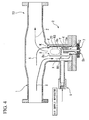
- FIG. 1 is a cross-sectional view showing the schematic structure of a burner apparatus S1 of the present embodiment.
- This burner apparatus S1 is connected to an exhaust outlet of an apparatus that expels exhaust gas such as a diesel engine or the like which is located on the upstream side of the burner apparatus S1.
- This burner apparatus S1 mixes together supplied exhaust gas X (i.e., an oxidizing agent) and fuel, and then combusts them so as to generate high-temperature gas Z. It also supplies this high-temperature gas Z to a downstream-side filter.
- the burner apparatus S1 is located, for example, between the diesel engine and a particulate filter, and is provided with a supply flow path 1 and a combustion unit 2.
- the supply flow path 1 is a flow path which is used to supply the exhaust gas X, which is supplied from the diesel engine or the like, directly to the filter.
- This supply flow path 1 is formed in a circular cylinder-shaped pipe. One end portion of this supply flow path 1 is connected to an exhaust outlet of the diesel engine or the like, while the other end portion thereof is connected to the filter.
- the combustion unit 2 is connected to the supply flow path 1. This combustion unit 2 mixes together a part of the exhaust gas X which flows through the supply flow path 1 and fuel therein, and then combusts them so as to generate high-temperature gas.
- This combustion unit 2 is provided with a pipe body 4, a fuel supply portion 5, an ignition system 7, a partitioning component 8, and a combustion supporting air supply apparatus 9.
- the pipe body 4 is a pipe-shaped component which forms the outer shape of the combustion unit 2, and has a hollow interior. This pipe body 4 is connected to the supply flow path 1 in a perpendicular direction relative to the direction in which the supply flow path 1 extends.
- the fuel supply portion 5 is provided with a fuel holding portion 5a which is located at the distal end of the ignition system 7, and with a supply portion 5b which is used to supply fuel to the fuel holding portion 5a.
- the fuel holding portion 5a is formed, for example, from metal, sintered metal, metal fibers, glass fabric, a ceramic porous body, ceramic fibers, or pumice or the like.
- the ignition system 7 includes a glow plug which is a heater which is heated to a temperature equal to or greater than the ignition temperature of the air-fuel mixture of fuel and the exhaust gas X, and a distal end portion thereof is surrounded by the fuel holding portion 5a.
- a glow plug which is a heater which is heated to a temperature equal to or greater than the ignition temperature of the air-fuel mixture of fuel and the exhaust gas X, and a distal end portion thereof is surrounded by the fuel holding portion 5a.
- the partitioning component 8 partitions the interior of the pipe body 4 into an exhaust gas flow path R1 through which exhaust gas X supplied from the supply flow path 1 flows, an ignition chamber R2 where the ignition system 7 is located, and a combustion holding chamber R3 where the combustion of the air-fuel mixture Y is maintained.
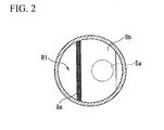
- This partitioning component 8 is provided with a central plate 8a which extends vertically in a central portion of the pipe body 4 and which is located away from a bottom surface of the pipe body 4. As is shown in FIG. 2 , this partitioning component 8 is also provided with a side plate 8b which extends horizontally from the central plate 8a and which is located away from a side surface of the pipe body 4.
- the surface area of the side plate 8b is set larger than the area viewed from above of the fuel holding portion 5a.
- this partitioning component 8 causes the exhaust gas X to flow from the exhaust gas flow path R1 to the ignition chamber R2 through a gap between the central plate 8a and the bottom surface of the pipe body 4, and causes the air-fuel mixture Y to flow from the ignition chamber R2 to the combustion holding chamber R3 through a gap between the side plate 8b and the side surface of the pipe body 4.
- This partitioning component 8 is positioned so that a gap is formed between itself and the pipe body 4, and causes the air-fuel mixture Y to pass from the ignition chamber R2 to the combustion holding chamber R3 through this gap.
- the flow rate of the air-fuel mixture Y is adjusted to a flow rate at which the combustion in the combustion holding chamber R3 is stabilized.
- the partitioning component 8 causes the air-fuel mixture Y to flow from below toward above through the gap opened adjacent to the pipe body 4. Because of this, the air-fuel mixture Y is made to collide with the flow of the exhaust gas X (i.e., the flow of an oxidizing agent) which is supplied from above the combustion holding chamber R3 (i.e., outside) along the side wall of the pipe body 4 to the combustion holding chamber R3.
- the cross-sectional area of the flow passage from the exhaust gas flow path R1 to the ignition chamber R2 is preferably larger than the cross-sectional area of the flow passage from the ignition chamber R2 to the combustion holding chamber R3.
- the combustion supporting air supply apparatus 9 accessorily supplies air to the interior of the pipe body 4 (i.e., to the exhaust gas flow path R1) as necessary.
- This combustion supporting air supply apparatus 9 is provided with an air supply apparatus which supplies air, and with piping and the like which connect this air supply apparatus to the interior of the pipe body 4.
- the exhaust gas X which flows from the supply flow path 1 to the exhaust gas flow path R1 is supplied as an oxidizing agent from the exhaust gas flow path R1 to the ignition chamber R2.
- the ignition system 7 is heated under the control of a control unit (not shown), and fuel which is supplied from the supply portion 5b to the fuel holding portion 5a is volatilized in the ignition chamber R2.
- the air-fuel mixture Y is created by mixing the exhaust gas X supplied to the ignition chamber R2 together with the volatilized fuel, and this air-fuel mixture Y is then ignited by being heated to a temperature equal to or more than its ignition temperature by the ignition system 7.
- the cross-sectional area of the flow passage from the exhaust gas flow path R1 to the ignition chamber R2 is set to be larger than the cross-sectional area of the flow passage from the ignition chamber R2 to the combustion holding chamber R3.
- the ignition chamber R2 and the combustion holding chamber R3 are partitioned by the partitioning component 8 such that the air-fuel mixture Y is able to pass between them. Furthermore, the flow rate of the air-fuel mixture Y supplied from the ignition chamber R2 to the combustion holding chamber R3 is adjusted to a flow rate at which the combustion in the combustion holding chamber R3 is stabilized. Therefore, according to the burner apparatus S1 of the present embodiment, it is possible to stabilize the combustion state of the air-fuel mixture Y, and to also generate the high-temperature gas Z stably.
- the air-fuel mixture Y which is supplied from the ignition chamber R2 to the combustion holding chamber R3 collides with the exhaust gas X which is supplied to the combustion holding chamber R3 from above. Consequently, it is possible to reduce the flow rates of the exhaust gas X and the air-fuel mixture Y in the combustion holding chamber R3, and the combustion taking place in the combustion holding chamber R3 can be made to proceed more stably.
- FIG. 3 is a cross-sectional view showing the schematic structure of a burner apparatus S2 of the present embodiment.
- the burner apparatus S2 of the present embodiment is provided with a combustion assisting component 10 which is placed in the combustion holding chamber R3.
- the combustion assisting component 10 assists the combustion in the combustion holding chamber R3, and inhibits any poor burning of the flame F.
- this combustion assisting component 10 it is possible to use a ceramic porous body that maintains the temperature of the combustion holding chamber at a high temperature by being heated by the flame F to equal to or more than the ignition temperature, or a catalyst or the like that is self-burned by being heated so as to inhibit any poor burning of the flame F.
- the burner apparatus S2 of the present embodiment which has the above described structure, because the combustion in the combustion holding chamber R3 is assisted by the combustion assisting component 10, it is possible to further stabilize the combustion in the combustion holding chamber R3.
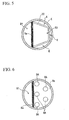
- FIG. 4 is a cross-sectional view showing the schematic structure of a burner apparatus S3 of the present embodiment.
- FIG. 5 is a view seen from above of a pipe body provided on the burner apparatus of the present embodiment.
- the burner apparatus S3 of the present embodiment is provided with a partitioning wall 20 (i.e., a partitioning wall) which separates the combustion holding chamber R3 from a wall surface of the pipe body 4 which is an external wall which is in contact with the outside air.
- a partitioning wall 20 i.e., a partitioning wall
- the partitioning wall 20 has an opened polygonal shape. Moreover, this partitioning wall 20 is supported by apex portions thereof being in contact with the circular pipe body 4. As a result, spaces K are formed between the partitioning wall 20 and an inner wall surface of the pipe body 4 in areas excluding the apex portions. By forming these spaces K, the combustion holding chamber R3 is separated from the wall surface of the pipe body 4.
- the pipe body 4 which is cooled to a low temperature to be exposed to the outside air is separated by the partitioning wall 20 via the spaces K from the combustion holding chamber R3. Consequently, it is possible to prevent the combustion holding chamber R3 from being cooled, and to further stabilize the combustion in the combustion holding chamber R3.
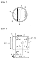
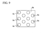
- FIG. 6 is a cross-sectional view showing the schematic structure of a burner apparatus S4 of the present embodiment, and is a view seen from above of a side plate 8b.
- the side plate 8b of the present embodiment is in contact with and is connected to the entire side wall of the pipe body 4 so as to entirely close off the space on the combustion holding chamber R3 side in the interior spaces of the pipe body 4 which have been divided in half by a central plate 8a.
- circular holes 8A i.e., through-holes
- that enable the air-fuel mixture Y to pass through are formed in the side plate 8b.
- a majority of the circular holes 8A are formed on the central plate 8a side (i.e., the upstream side), in contrast a minority of the circular holes 8A are formed on the inner wall side (i.e., the downstream side) of the pipe body 4.
- the opening area created by the circular holes 8A in the side plate 8b is relatively large on the upstream side in the flow direction of the air-fuel mixture Y, and is relatively small on the downstream side thereof.
- the air-fuel mixture Y is supplied to the combustion holding chamber R3 through the narrow circular holes 8A.
- the flow of the air-fuel mixture Y is stirred, so that the mixing of the air-fuel mixture Y in the combustion holding chamber R3 is accelerated, and a preferable combustion of the air-fuel mixture can be achieved.
- the opening area in the side plate 8b is relatively large on the upstream side in the flow direction of the air-fuel mixture Y, and is relatively small on the downstream side thereof.
- the opening area on the upstream side of the side plate 8b is approximately 1.5 times the opening area on the downstream side thereof. It is also desirable for the sum of the areas of all of the circular holes 8A to be between 5% and 20% of the internal cross-sectional area of the pipe body 4a.
- the through-holes are in the form of the circular holes 8A, however, for example, as is shown in FIG. 7 , it is also possible for the through-holes to be in the form of elongated holes 8B.
- the opening area in the side plate 8b it is preferable for the opening area in the side plate 8b to be relatively large on the upstream side in the flow direction of the air-fuel mixture Y, and to be relatively small on the downstream side thereof. It is also preferable to make the elongated holes 8B on the upstream side in the flow direction of the air-fuel mixture Y relatively long, and to make the elongated holes 8B on the downstream side thereof relatively short.
- the air-fuel mixture Y flows from the ignition chamber R2 to the combustion holding chamber R3 through the gap that is formed by the side plate 8b being separated from the side surface of the pipe body 4.
- the present invention is not limited to this.
- the horizontal width ⁇ of the side plate 8b i.e., the width thereof in a perpendicular direction relative to the surface of the central plate 8a
- the vertical width ⁇ of the side plate 8b i.e., the width thereof in a direction along the surface of the central plate 8a
- the horizontal width of the exhaust gas flow path R1 i.e., the width thereof in a perpendicular direction relative to the surface of the central plate 8a
- the vertical width of the exhaust gas flow path R1 i.e., the width thereof in a direction along the surface of the central plate 8a
- the diameter of the through-holes 8c is 0.19 ⁇ (found by experiment to be approximately 8 mm), and a total of 5 through-holes 8c are located at the four corners and at the center of the side plate 8b. Furthermore, the centers of the through-holes 8c that are located at the four corners of the side plate 8b are located at a position of 0.1 ⁇ from the edges in the horizontal width direction of the side plate 8b, and at a position of 0.15 ⁇ from the edges in the vertical width direction of the side plate 8b.
- the center of the through-hole 8c that is located in the center of the side plate 8b is located at a position between 0.3 ⁇ and 0.5 ⁇ from the surface of the central plate 8a, and at a position of the middle in the horizontal width direction of the side plate 8b.
- the combustion supporting air supply apparatus 9 is provided. However, when the density of the oxygen contained in the exhaust gas X is sufficiently high, it is possible to omit the combustion supporting air supply apparatus 9.
- the pipe body 4, the internal structure thereof, and the connecting structure are mounted above the supply flow path 1.
- the pipe body 4, the internal structure thereof, and the connecting structure are provided on the burner apparatus S1 of the above described first embodiment so as to be symmetrically inverted vertically.
- the pipe body 4, the internal structure thereof, and the connecting structure are provided on the burner apparatuses S2 to S4 of the second through fourth embodiments as well as on variant examples thereof, so as to be symmetrically inverted vertically.
- the supply portion 5b which is connected to the fuel holding portion 5a is used.
- the present invention is not limited to this and it is also possible to use a supply portion that sprays fuel onto the fuel holding portion 5a.
- an ignition chamber and a combustion holding chamber are partitioned by a partitioning component so that air-fuel mixture is able to pass between them. Because of this, it is possible to adjust the flow rate of the air-fuel mixture supplied from the ignition chamber to the combustion holding chamber. In other words, it is possible to adjust the flow rate of the air-fuel mixture supplied to the combustion holding chamber to a flow rate at which the combustion in the combustion holding chamber is stabilized. Therefore, according to the burner apparatus of the present invention, it is possible to stabilize the combustion state of the air-fuel mixture, and to also generate high-temperature gas stably.
Landscapes
- Engineering & Computer Science (AREA)
- Chemical & Material Sciences (AREA)
- Combustion & Propulsion (AREA)
- Mechanical Engineering (AREA)
- General Engineering & Computer Science (AREA)
- Processes For Solid Components From Exhaust (AREA)
Applications Claiming Priority (3)
| Application Number | Priority Date | Filing Date | Title |
|---|---|---|---|
| JP2009165869 | 2009-07-14 | ||
| JP2009226713A JP4720935B2 (ja) | 2009-07-14 | 2009-09-30 | バーナ装置 |
| PCT/JP2010/061915 WO2011007808A1 (ja) | 2009-07-14 | 2010-07-14 | バーナ装置 |
Publications (3)
| Publication Number | Publication Date |
|---|---|
| EP2455663A1 EP2455663A1 (en) | 2012-05-23 |
| EP2455663A4 EP2455663A4 (en) | 2012-05-23 |
| EP2455663B1 true EP2455663B1 (en) | 2013-11-20 |
Family
ID=43449416
Family Applications (1)
| Application Number | Title | Priority Date | Filing Date |
|---|---|---|---|
| EP10799866.8A Not-in-force EP2455663B1 (en) | 2009-07-14 | 2010-07-14 | Burner apparatus |
Country Status (7)
| Country | Link |
|---|---|
| US (1) | US8733085B2 (enExample) |
| EP (1) | EP2455663B1 (enExample) |
| JP (1) | JP4720935B2 (enExample) |
| KR (1) | KR101358100B1 (enExample) |
| CN (1) | CN102472490B (enExample) |
| CA (1) | CA2767366C (enExample) |
| WO (1) | WO2011007808A1 (enExample) |
Families Citing this family (3)
| Publication number | Priority date | Publication date | Assignee | Title |
|---|---|---|---|---|
| JP5549915B2 (ja) * | 2009-09-30 | 2014-07-16 | 株式会社Ihi | バーナ装置 |
| CN102803850B (zh) * | 2010-03-24 | 2015-03-25 | 株式会社Ihi | 燃烧器装置 |
| FR3002024B1 (fr) * | 2013-02-12 | 2015-02-06 | Jose Cousseau | Installation de production et de traitement de fumees |
Family Cites Families (20)
| Publication number | Priority date | Publication date | Assignee | Title |
|---|---|---|---|---|
| DE3729861C2 (de) | 1987-09-05 | 1995-06-22 | Deutsche Forsch Luft Raumfahrt | Verfahren zum Betreiben einer Rußfiltervorrichtung für einen Dieselmotor und Rußfiltervorrichtung zur Durchführung dieses Verfahrens |
| JPH08580Y2 (ja) * | 1989-11-16 | 1996-01-10 | 株式会社ゼクセル | 燃焼式暖房装置 |
| US5379592A (en) * | 1991-10-23 | 1995-01-10 | Waschkuttis; Gerhard | Catalytic converter with ignition burner |
| JP3282944B2 (ja) | 1994-07-18 | 2002-05-20 | トヨタ自動車株式会社 | 低NOxバーナ |
| JPH0893555A (ja) | 1994-07-26 | 1996-04-09 | Ishikawajima Harima Heavy Ind Co Ltd | ラム燃焼装置 |
| JP2980533B2 (ja) * | 1995-02-24 | 1999-11-22 | 株式会社サムソン | 予混合式ガスバーナ |
| JP3341800B2 (ja) | 1995-03-23 | 2002-11-05 | イビデン株式会社 | Dpfバーナー再生装置 |
| US5829248A (en) | 1997-06-19 | 1998-11-03 | Environmental Engineering Corp. | Anti-pollution system |
| JP2000110548A (ja) * | 1998-10-01 | 2000-04-18 | Mitsubishi Heavy Ind Ltd | 黒煙除去装置 |
| US6777650B1 (en) * | 2000-02-04 | 2004-08-17 | Saint-Gobtain Industrial Ceramics, Inc. | Igniter shields |
| CA2410725C (en) | 2001-11-16 | 2008-07-22 | Hitachi, Ltd. | Solid fuel burner, burning method using the same, combustion apparatus and method of operating the combustion apparatus |
| JP4055710B2 (ja) * | 2002-02-19 | 2008-03-05 | 泰雄 鯵坂 | ディーゼル排気ガスの浄化フィルタ |
| JP2004324587A (ja) | 2003-04-25 | 2004-11-18 | Mitsubishi Fuso Truck & Bus Corp | 内燃機関の排気浄化装置 |
| JP4167613B2 (ja) * | 2004-03-19 | 2008-10-15 | 株式会社サムソン | パイロットバーナ部を持った予混合式ガスバーナ |
| DE102004048335B4 (de) * | 2004-10-01 | 2007-04-12 | J. Eberspächer GmbH & Co. KG | Abgasanlage für eine Brennkraftmaschine und zugehöriges Betriebsverfahren |
| JP2007154772A (ja) | 2005-12-06 | 2007-06-21 | Mitsubishi Fuso Truck & Bus Corp | 内燃機関の制御装置 |
| KR100748660B1 (ko) * | 2005-12-13 | 2007-08-10 | 현대자동차주식회사 | 디젤 매연 필터의 재생 시스템 및 재생 방법 |
| US20090178394A1 (en) * | 2008-01-15 | 2009-07-16 | Crane Jr Samuel N | Method and Apparatus for Cleaning Electrodes of a Fuel-Fired Burner of an Emission Abatement Assembly |
| JP2009226713A (ja) | 2008-03-21 | 2009-10-08 | Seiko Epson Corp | 液体吐出方法、及び液体吐出装置の製造方法 |
| JP4865831B2 (ja) | 2009-04-30 | 2012-02-01 | 株式会社藤商事 | 遊技機 |
-
2009
- 2009-09-30 JP JP2009226713A patent/JP4720935B2/ja not_active Expired - Fee Related
-
2010
- 2010-07-14 CA CA2767366A patent/CA2767366C/en not_active Expired - Fee Related
- 2010-07-14 KR KR1020117031476A patent/KR101358100B1/ko not_active Expired - Fee Related
- 2010-07-14 US US13/376,511 patent/US8733085B2/en not_active Expired - Fee Related
- 2010-07-14 CN CN201080031286.XA patent/CN102472490B/zh not_active Expired - Fee Related
- 2010-07-14 WO PCT/JP2010/061915 patent/WO2011007808A1/ja not_active Ceased
- 2010-07-14 EP EP10799866.8A patent/EP2455663B1/en not_active Not-in-force
Also Published As
| Publication number | Publication date |
|---|---|
| KR101358100B1 (ko) | 2014-02-04 |
| CA2767366A1 (en) | 2011-01-20 |
| US20120096840A1 (en) | 2012-04-26 |
| CN102472490A (zh) | 2012-05-23 |
| CN102472490B (zh) | 2014-12-31 |
| KR20120031184A (ko) | 2012-03-30 |
| JP4720935B2 (ja) | 2011-07-13 |
| EP2455663A1 (en) | 2012-05-23 |
| US8733085B2 (en) | 2014-05-27 |
| WO2011007808A1 (ja) | 2011-01-20 |
| CA2767366C (en) | 2014-07-08 |
| JP2011038504A (ja) | 2011-02-24 |
| EP2455663A4 (en) | 2012-05-23 |
Similar Documents
| Publication | Publication Date | Title |
|---|---|---|
| CA2794191C (en) | Burner device | |
| EP2455663B1 (en) | Burner apparatus | |
| EP2455664B1 (en) | Burner device | |
| JP2011099582A (ja) | バーナ装置 | |
| JP5521465B2 (ja) | バーナ装置 | |
| JP5671794B2 (ja) | バーナ装置 | |
| JP5568996B2 (ja) | バーナ装置 | |
| JP5428712B2 (ja) | バーナ装置 | |
| JP5614115B2 (ja) | バーナ装置 | |
| JP5549915B2 (ja) | バーナ装置 | |
| JP5742128B2 (ja) | バーナ装置 | |
| JP2011074820A (ja) | バーナ装置 | |
| JP2011226404A (ja) | 着火装置 |
Legal Events
| Date | Code | Title | Description |
|---|---|---|---|
| PUAI | Public reference made under article 153(3) epc to a published international application that has entered the european phase |
Free format text: ORIGINAL CODE: 0009012 |
|
| 17P | Request for examination filed |
Effective date: 20111206 |
|
| A4 | Supplementary search report drawn up and despatched |
Effective date: 20120320 |
|
| AK | Designated contracting states |
Kind code of ref document: A1 Designated state(s): AL AT BE BG CH CY CZ DE DK EE ES FI FR GB GR HR HU IE IS IT LI LT LU LV MC MK MT NL NO PL PT RO SE SI SK SM TR |
|
| DAX | Request for extension of the european patent (deleted) | ||
| GRAP | Despatch of communication of intention to grant a patent |
Free format text: ORIGINAL CODE: EPIDOSNIGR1 |
|
| INTG | Intention to grant announced |
Effective date: 20130614 |
|
| GRAS | Grant fee paid |
Free format text: ORIGINAL CODE: EPIDOSNIGR3 |
|
| GRAA | (expected) grant |
Free format text: ORIGINAL CODE: 0009210 |
|
| AK | Designated contracting states |
Kind code of ref document: B1 Designated state(s): AL AT BE BG CH CY CZ DE DK EE ES FI FR GB GR HR HU IE IS IT LI LT LU LV MC MK MT NL NO PL PT RO SE SI SK SM TR |
|
| REG | Reference to a national code |
Ref country code: GB Ref legal event code: FG4D |
|
| REG | Reference to a national code |
Ref country code: CH Ref legal event code: EP |
|
| REG | Reference to a national code |
Ref country code: AT Ref legal event code: REF Ref document number: 641867 Country of ref document: AT Kind code of ref document: T Effective date: 20131215 |
|
| REG | Reference to a national code |
Ref country code: IE Ref legal event code: FG4D |
|
| REG | Reference to a national code |
Ref country code: DE Ref legal event code: R096 Ref document number: 602010011971 Country of ref document: DE Effective date: 20140116 |
|
| REG | Reference to a national code |
Ref country code: NL Ref legal event code: VDEP Effective date: 20131120 |
|
| REG | Reference to a national code |
Ref country code: AT Ref legal event code: MK05 Ref document number: 641867 Country of ref document: AT Kind code of ref document: T Effective date: 20131120 |
|
| REG | Reference to a national code |
Ref country code: LT Ref legal event code: MG4D |
|
| PG25 | Lapsed in a contracting state [announced via postgrant information from national office to epo] |
Ref country code: FI Free format text: LAPSE BECAUSE OF FAILURE TO SUBMIT A TRANSLATION OF THE DESCRIPTION OR TO PAY THE FEE WITHIN THE PRESCRIBED TIME-LIMIT Effective date: 20131120 Ref country code: NO Free format text: LAPSE BECAUSE OF FAILURE TO SUBMIT A TRANSLATION OF THE DESCRIPTION OR TO PAY THE FEE WITHIN THE PRESCRIBED TIME-LIMIT Effective date: 20140220 Ref country code: IS Free format text: LAPSE BECAUSE OF FAILURE TO SUBMIT A TRANSLATION OF THE DESCRIPTION OR TO PAY THE FEE WITHIN THE PRESCRIBED TIME-LIMIT Effective date: 20140320 Ref country code: NL Free format text: LAPSE BECAUSE OF FAILURE TO SUBMIT A TRANSLATION OF THE DESCRIPTION OR TO PAY THE FEE WITHIN THE PRESCRIBED TIME-LIMIT Effective date: 20131120 Ref country code: SE Free format text: LAPSE BECAUSE OF FAILURE TO SUBMIT A TRANSLATION OF THE DESCRIPTION OR TO PAY THE FEE WITHIN THE PRESCRIBED TIME-LIMIT Effective date: 20131120 Ref country code: LT Free format text: LAPSE BECAUSE OF FAILURE TO SUBMIT A TRANSLATION OF THE DESCRIPTION OR TO PAY THE FEE WITHIN THE PRESCRIBED TIME-LIMIT Effective date: 20131120 Ref country code: HR Free format text: LAPSE BECAUSE OF FAILURE TO SUBMIT A TRANSLATION OF THE DESCRIPTION OR TO PAY THE FEE WITHIN THE PRESCRIBED TIME-LIMIT Effective date: 20131120 |
|
| PG25 | Lapsed in a contracting state [announced via postgrant information from national office to epo] |
Ref country code: AT Free format text: LAPSE BECAUSE OF FAILURE TO SUBMIT A TRANSLATION OF THE DESCRIPTION OR TO PAY THE FEE WITHIN THE PRESCRIBED TIME-LIMIT Effective date: 20131120 Ref country code: BE Free format text: LAPSE BECAUSE OF FAILURE TO SUBMIT A TRANSLATION OF THE DESCRIPTION OR TO PAY THE FEE WITHIN THE PRESCRIBED TIME-LIMIT Effective date: 20131120 Ref country code: ES Free format text: LAPSE BECAUSE OF FAILURE TO SUBMIT A TRANSLATION OF THE DESCRIPTION OR TO PAY THE FEE WITHIN THE PRESCRIBED TIME-LIMIT Effective date: 20131120 Ref country code: LV Free format text: LAPSE BECAUSE OF FAILURE TO SUBMIT A TRANSLATION OF THE DESCRIPTION OR TO PAY THE FEE WITHIN THE PRESCRIBED TIME-LIMIT Effective date: 20131120 |
|
| PG25 | Lapsed in a contracting state [announced via postgrant information from national office to epo] |
Ref country code: PT Free format text: LAPSE BECAUSE OF FAILURE TO SUBMIT A TRANSLATION OF THE DESCRIPTION OR TO PAY THE FEE WITHIN THE PRESCRIBED TIME-LIMIT Effective date: 20140320 |
|
| PG25 | Lapsed in a contracting state [announced via postgrant information from national office to epo] |
Ref country code: EE Free format text: LAPSE BECAUSE OF FAILURE TO SUBMIT A TRANSLATION OF THE DESCRIPTION OR TO PAY THE FEE WITHIN THE PRESCRIBED TIME-LIMIT Effective date: 20131120 |
|
| REG | Reference to a national code |
Ref country code: DE Ref legal event code: R097 Ref document number: 602010011971 Country of ref document: DE |
|
| PG25 | Lapsed in a contracting state [announced via postgrant information from national office to epo] |
Ref country code: SK Free format text: LAPSE BECAUSE OF FAILURE TO SUBMIT A TRANSLATION OF THE DESCRIPTION OR TO PAY THE FEE WITHIN THE PRESCRIBED TIME-LIMIT Effective date: 20131120 Ref country code: CZ Free format text: LAPSE BECAUSE OF FAILURE TO SUBMIT A TRANSLATION OF THE DESCRIPTION OR TO PAY THE FEE WITHIN THE PRESCRIBED TIME-LIMIT Effective date: 20131120 Ref country code: PL Free format text: LAPSE BECAUSE OF FAILURE TO SUBMIT A TRANSLATION OF THE DESCRIPTION OR TO PAY THE FEE WITHIN THE PRESCRIBED TIME-LIMIT Effective date: 20131120 Ref country code: RO Free format text: LAPSE BECAUSE OF FAILURE TO SUBMIT A TRANSLATION OF THE DESCRIPTION OR TO PAY THE FEE WITHIN THE PRESCRIBED TIME-LIMIT Effective date: 20131120 |
|
| PLBE | No opposition filed within time limit |
Free format text: ORIGINAL CODE: 0009261 |
|
| STAA | Information on the status of an ep patent application or granted ep patent |
Free format text: STATUS: NO OPPOSITION FILED WITHIN TIME LIMIT |
|
| PG25 | Lapsed in a contracting state [announced via postgrant information from national office to epo] |
Ref country code: DK Free format text: LAPSE BECAUSE OF FAILURE TO SUBMIT A TRANSLATION OF THE DESCRIPTION OR TO PAY THE FEE WITHIN THE PRESCRIBED TIME-LIMIT Effective date: 20131120 |
|
| 26N | No opposition filed |
Effective date: 20140821 |
|
| REG | Reference to a national code |
Ref country code: DE Ref legal event code: R097 Ref document number: 602010011971 Country of ref document: DE Effective date: 20140821 |
|
| PG25 | Lapsed in a contracting state [announced via postgrant information from national office to epo] |
Ref country code: LU Free format text: LAPSE BECAUSE OF FAILURE TO SUBMIT A TRANSLATION OF THE DESCRIPTION OR TO PAY THE FEE WITHIN THE PRESCRIBED TIME-LIMIT Effective date: 20140714 Ref country code: SI Free format text: LAPSE BECAUSE OF FAILURE TO SUBMIT A TRANSLATION OF THE DESCRIPTION OR TO PAY THE FEE WITHIN THE PRESCRIBED TIME-LIMIT Effective date: 20131120 |
|
| REG | Reference to a national code |
Ref country code: CH Ref legal event code: PL |
|
| REG | Reference to a national code |
Ref country code: IE Ref legal event code: MM4A |
|
| PG25 | Lapsed in a contracting state [announced via postgrant information from national office to epo] |
Ref country code: CH Free format text: LAPSE BECAUSE OF NON-PAYMENT OF DUE FEES Effective date: 20140731 Ref country code: LI Free format text: LAPSE BECAUSE OF NON-PAYMENT OF DUE FEES Effective date: 20140731 |
|
| PG25 | Lapsed in a contracting state [announced via postgrant information from national office to epo] |
Ref country code: IE Free format text: LAPSE BECAUSE OF NON-PAYMENT OF DUE FEES Effective date: 20140714 |
|
| PG25 | Lapsed in a contracting state [announced via postgrant information from national office to epo] |
Ref country code: SM Free format text: LAPSE BECAUSE OF FAILURE TO SUBMIT A TRANSLATION OF THE DESCRIPTION OR TO PAY THE FEE WITHIN THE PRESCRIBED TIME-LIMIT Effective date: 20131120 Ref country code: MC Free format text: LAPSE BECAUSE OF FAILURE TO SUBMIT A TRANSLATION OF THE DESCRIPTION OR TO PAY THE FEE WITHIN THE PRESCRIBED TIME-LIMIT Effective date: 20131120 |
|
| REG | Reference to a national code |
Ref country code: FR Ref legal event code: PLFP Year of fee payment: 7 |
|
| PG25 | Lapsed in a contracting state [announced via postgrant information from national office to epo] |
Ref country code: GR Free format text: LAPSE BECAUSE OF FAILURE TO SUBMIT A TRANSLATION OF THE DESCRIPTION OR TO PAY THE FEE WITHIN THE PRESCRIBED TIME-LIMIT Effective date: 20140221 Ref country code: CY Free format text: LAPSE BECAUSE OF FAILURE TO SUBMIT A TRANSLATION OF THE DESCRIPTION OR TO PAY THE FEE WITHIN THE PRESCRIBED TIME-LIMIT Effective date: 20131120 Ref country code: MT Free format text: LAPSE BECAUSE OF FAILURE TO SUBMIT A TRANSLATION OF THE DESCRIPTION OR TO PAY THE FEE WITHIN THE PRESCRIBED TIME-LIMIT Effective date: 20131120 Ref country code: BG Free format text: LAPSE BECAUSE OF FAILURE TO SUBMIT A TRANSLATION OF THE DESCRIPTION OR TO PAY THE FEE WITHIN THE PRESCRIBED TIME-LIMIT Effective date: 20131120 |
|
| PG25 | Lapsed in a contracting state [announced via postgrant information from national office to epo] |
Ref country code: HU Free format text: LAPSE BECAUSE OF FAILURE TO SUBMIT A TRANSLATION OF THE DESCRIPTION OR TO PAY THE FEE WITHIN THE PRESCRIBED TIME-LIMIT; INVALID AB INITIO Effective date: 20100714 Ref country code: TR Free format text: LAPSE BECAUSE OF FAILURE TO SUBMIT A TRANSLATION OF THE DESCRIPTION OR TO PAY THE FEE WITHIN THE PRESCRIBED TIME-LIMIT Effective date: 20131120 |
|
| PGFP | Annual fee paid to national office [announced via postgrant information from national office to epo] |
Ref country code: FR Payment date: 20160613 Year of fee payment: 7 |
|
| PGFP | Annual fee paid to national office [announced via postgrant information from national office to epo] |
Ref country code: DE Payment date: 20160705 Year of fee payment: 7 Ref country code: GB Payment date: 20160713 Year of fee payment: 7 Ref country code: IT Payment date: 20160720 Year of fee payment: 7 |
|
| REG | Reference to a national code |
Ref country code: DE Ref legal event code: R119 Ref document number: 602010011971 Country of ref document: DE |
|
| GBPC | Gb: european patent ceased through non-payment of renewal fee |
Effective date: 20170714 |
|
| REG | Reference to a national code |
Ref country code: FR Ref legal event code: ST Effective date: 20180330 |
|
| PG25 | Lapsed in a contracting state [announced via postgrant information from national office to epo] |
Ref country code: DE Free format text: LAPSE BECAUSE OF NON-PAYMENT OF DUE FEES Effective date: 20180201 Ref country code: GB Free format text: LAPSE BECAUSE OF NON-PAYMENT OF DUE FEES Effective date: 20170714 |
|
| PG25 | Lapsed in a contracting state [announced via postgrant information from national office to epo] |
Ref country code: FR Free format text: LAPSE BECAUSE OF NON-PAYMENT OF DUE FEES Effective date: 20170731 |
|
| PG25 | Lapsed in a contracting state [announced via postgrant information from national office to epo] |
Ref country code: MK Free format text: LAPSE BECAUSE OF FAILURE TO SUBMIT A TRANSLATION OF THE DESCRIPTION OR TO PAY THE FEE WITHIN THE PRESCRIBED TIME-LIMIT Effective date: 20131120 |
|
| PG25 | Lapsed in a contracting state [announced via postgrant information from national office to epo] |
Ref country code: IT Free format text: LAPSE BECAUSE OF NON-PAYMENT OF DUE FEES Effective date: 20170714 |
|
| PG25 | Lapsed in a contracting state [announced via postgrant information from national office to epo] |
Ref country code: AL Free format text: LAPSE BECAUSE OF FAILURE TO SUBMIT A TRANSLATION OF THE DESCRIPTION OR TO PAY THE FEE WITHIN THE PRESCRIBED TIME-LIMIT Effective date: 20131120 |