EP2455261A1 - Vorrichtung zur Anbringung eines Sicherheitsgurtes sowie Sitzanordnung - Google Patents
Vorrichtung zur Anbringung eines Sicherheitsgurtes sowie Sitzanordnung Download PDFInfo
- Publication number
- EP2455261A1 EP2455261A1 EP11009052A EP11009052A EP2455261A1 EP 2455261 A1 EP2455261 A1 EP 2455261A1 EP 11009052 A EP11009052 A EP 11009052A EP 11009052 A EP11009052 A EP 11009052A EP 2455261 A1 EP2455261 A1 EP 2455261A1
- Authority
- EP
- European Patent Office
- Prior art keywords
- seat
- mounting unit
- unit
- belt
- anchoring
- Prior art date
- Legal status (The legal status is an assumption and is not a legal conclusion. Google has not performed a legal analysis and makes no representation as to the accuracy of the status listed.)
- Granted
Links
- 238000004873 anchoring Methods 0.000 claims abstract description 25
- 230000008878 coupling Effects 0.000 claims description 8
- 238000010168 coupling process Methods 0.000 claims description 8
- 238000005859 coupling reaction Methods 0.000 claims description 8
- 238000003780 insertion Methods 0.000 claims description 5
- 230000037431 insertion Effects 0.000 claims description 5
- 238000010276 construction Methods 0.000 claims description 2
- 230000001419 dependent effect Effects 0.000 description 1
- QOWAEJDMPSSSJP-WKNCGDISSA-N lipid-associating peptide Chemical compound C([C@H](NC(=O)[C@H](CCC(O)=O)NC(=O)[C@H](CCCCN)NC(=O)[C@@H](NC(=O)[C@H](CO)NC(=O)[C@@H](N)CO)CC(C)C)C(=O)N[C@@H](CC=1C2=CC=CC=C2NC=1)C(=O)N[C@@H](CO)C(=O)N[C@@H](CO)C(=O)N[C@@H](CC(C)C)C(=O)N[C@@H](CCCCN)C(=O)N[C@@H](CCC(O)=O)C(=O)N[C@@H](CO)C(=O)N[C@@H](CC=1C=CC=CC=1)C(=O)N[C@@H](CO)C(O)=O)C1=CC=C(O)C=C1 QOWAEJDMPSSSJP-WKNCGDISSA-N 0.000 description 1
- 108010071296 lipid-associating peptides Proteins 0.000 description 1
- 239000007787 solid Substances 0.000 description 1
Images

Classifications
-
- B—PERFORMING OPERATIONS; TRANSPORTING
- B60—VEHICLES IN GENERAL
- B60R—VEHICLES, VEHICLE FITTINGS, OR VEHICLE PARTS, NOT OTHERWISE PROVIDED FOR
- B60R22/00—Safety belts or body harnesses in vehicles
- B60R22/18—Anchoring devices
- B60R22/26—Anchoring devices secured to the seat
-
- B—PERFORMING OPERATIONS; TRANSPORTING
- B60—VEHICLES IN GENERAL
- B60N—SEATS SPECIALLY ADAPTED FOR VEHICLES; VEHICLE PASSENGER ACCOMMODATION NOT OTHERWISE PROVIDED FOR
- B60N2/00—Seats specially adapted for vehicles; Arrangement or mounting of seats in vehicles
- B60N2/68—Seat frames
- B60N2/682—Joining means
- B60N2002/684—Joining means the back rest being mounted or joined with an easy attachment system to the seat
-
- B—PERFORMING OPERATIONS; TRANSPORTING
- B60—VEHICLES IN GENERAL
- B60R—VEHICLES, VEHICLE FITTINGS, OR VEHICLE PARTS, NOT OTHERWISE PROVIDED FOR
- B60R22/00—Safety belts or body harnesses in vehicles
- B60R22/18—Anchoring devices
- B60R2022/1818—Belt guides
Definitions
- the invention relates to a device for attaching a safety belt according to the preamble of claim 1 and a seat assembly with a seat and a device for attaching a safety belt.
- racks that are designed to attach seat belts.
- the z. B. are anchored to a vehicle floor, are regularly performed as a tubular frame.
- the invention is based, especially in mobile homes, to increase the number of seats while driving the task.
- the invention relates to a device for attaching a seatbelt in a vehicle, in particular a motorhome, which comprises a mounting unit which is designed so that a belt buckle and a belt reel can be mounted thereon.
- the core of the invention resides in the fact that an anchoring unit is arranged on the mounting unit, with which the mounting unit can be connected to a seat located in front of the mounting unit in the direction of travel, so that the mounting unit derive tensile forces via the anchoring unit when the anchoring unit is arranged in front of the seat can.
- a longitudinal seat can thus still use as a seat for a ride, for which longitudinal seats are not allowed in principle.
- the mounting unit comprises a cross-member, which is preferably transverse to a longitudinal seat, that is arranged transversely to the direction of travel and the z. B is equipped in its end with a lap belt with buckle.
- the mounting unit preferably comprises on a bottom attachment means for anchoring the Mounting unit to a substructure, z. B. seat box of a longitudinal seat.
- the mounting unit is pluggable. This makes it possible to set up an additional seat for the ride only temporarily, if necessary.
- the mounting unit is a backrest support structure, for. B. includes a tubular frame.
- a tubular frame can z. B. be mounted on a cross-beam of the mounting unit, projecting from a pointing to a seat portion of the cross-beam insertion elements, the z. B. fit into matching shots on the substructure, so that the whole unit can be easily inserted and unplugged. So that the anchoring unit can be easily assembled and disassembled, it is further suggested that a coupling piece, for. B. a buckle for the coupling of a traction means of the anchoring means is attached. The coupling piece is then preferably suitable for a Gurtend Gla, for example, a tongue.
- the anchoring unit is z. B. anchored to a front seat in the side area.
- the mounting unit can be unplugged for stowage at a suitable location together with the backrest and disconnected via the coupling piece of the remaining anchoring unit.
- the remaining anchoring unit is for example a belt retractor, on which then the belt can be rolled up to stow it properly.
- a hinge for mounting a folding seat is arranged on the mounting unit, preferably with a seat surface.
- a lap belt is then preferably provided on such a mounting unit.
- the seating position is opposite to the direction of travel.
- a seat box insertion elements for fixed mounting on the substructure are available, in which insertion of the mounting unit fit.
- the z. B. can absorb forces on the mounting unit in the direction of travel.
- a longitudinal seat 2 is located in the Fig. 1 and 2 .
- the passenger seat 1 and the longitudinal seat 2 are z. B. installed in a motor home.
- the longitudinal seat 2 can be used as a seat when the vehicle is stationary. A However, seating for driving must be either in or against the direction of travel.
- the longitudinal seat 2 is available as a seat opportunity for a driving operation, it is equipped with a seat device 3, whereby the longitudinal seat 2 is used as a seat against the direction of travel 3.
- a substructure 4 of the longitudinal seat 2 is equipped with receiving elements 5, 6.
- the receiving element 6 is mounted on a seat bottom 13, whereas the receiving element 5 is attached to a side wall 20 of the substructure 4.
- the receiving elements 5, 6 can be inserted by means of male elements 7, 8, a mounting unit 9 with lap belt 10 and backrest 11.
- the backrest 11 is z. B. equipped with a back pad 12.
- the seat bottom 13 is provided with a seat support 13a.
- a lap belt 14 is attached.
- a belt lock 15 is mounted approximately centrally on the opposite side of the backrest on the mounting unit 9.
- a matching counterpart can be clicked, which forms the end of a belt 17 which is mounted on a belt retractor 18 on the passenger seat 1 in the back region.
- an anchoring unit 19 which is able to absorb tensile forces, which are introduced via the lap belt 14 in the mounting unit 9.
- a substantially rigid anchoring unit is also conceivable.
- the setting device 3 is equipped so that legal stability devices are met. Alone the attachment to the base 4 of the longitudinal seat 2 could not provide the necessary forces.
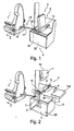
- Fig. 3 shows parts for the construction of a seat arrangement according to the invention.
- the central component is a mounting unit 21.
- the mounting unit 21 consists of a cross-beam 22 and a tubular frame 23 arranged thereon, which forms the base for a backrest.
- two male members 24, 25 for matching female members 26, 27 are provided at the cross-beam.
- the receiving elements 26, 27 are attached to a substructure z. B, a longitudinal seat attached, for example, as in the Fig. 1 and 2
- a fixing screw 28 is provided which can be screwed into a receiving tube 29 of the receiving unit 26 as soon as the plug-in part 24 is inserted and positioned therein.
- cross-beam 22 comprises fastening screws 30, 31 for the arrangement of parts of a belt, for. B. lap belt 14, which are bolted to end faces of the crossbeam 22.
- a coupling piece for an anchoring unit can be attached to the crossbeam 22 via screw means 32.
- hinge parts 33, 34 are provided which are hinged to each other via hinge pins 35.
- a seat can be screwed.
- a mounting bracket 36 the z. B. on the right outside of a passenger seat via screws 37, 38 can be attached to a further belt 39, a belt, for. B. to assemble a belt retractor with belt, which is then attachable to a bolted to the crossbeam 22 coupling piece.
Landscapes
- Engineering & Computer Science (AREA)
- Mechanical Engineering (AREA)
- Aviation & Aerospace Engineering (AREA)
- Transportation (AREA)
- Automotive Seat Belt Assembly (AREA)
- Seats For Vehicles (AREA)
Abstract
Description
- Die Erfindung betrifft eine Vorrichtung zur Anbringung eines Sicherheitsgurtes nach dem Oberbegriff des Anspruchs 1 sowie eine Sitzanordnung mit einer Sitzbank und einer Vorrichtung zur Anbringung eines Sicherheitsgurtes.
- In Fahrzeugen, insbesondere im Wohnraum von Wohnmobilen gibt es Gestelle, die dafür ausgestaltet sind, Sicherheitsgurte anzubringen. Derartige Gestelle, die z. B. an einem Fahrzeugboden verankerbar sind, werden regelmäßig als Rohrrahmen ausgeführt.
- Damit lassen sich im Wohnbereich eines Wohnmobils auf einer Sitzbank z. B. zwei Sitzplätze mit Gurten ausstatten.
- Ein Anliegen in Wohnmobilen ist stets das zur Verfügung stellen von ausreichend "Fahrt-Sitzplätzen" vor dem Hintergrund, dass längs in Fahrtrichtung angeordnete Sitzplätze, insbesondere Sitzbänke, bei welchen Personen quer zur Fahrtrichtung sitzen, aus gesetzlichen Bestimmungen keine zugelassenen Sitzplätze während der Fahrt darstellen können.
- Der Erfindung liegt die Aufgabe zugrunde, insbesondere in Wohnmobilen, die Sitzplatzzahl während der Fahrt erhöhen zu können.
- Diese Aufgabe wird durch die Merkmale des Anspruchs 1 gelöst.
- In den abhängigen Ansprüchen sind vorteilhafte und zweckmäßige Weiterbildung der Erfindung angegeben.
- Die Erfindung geht von einer Vorrichtung zur Anbringung eines Sicherheitsgurtes in einem Fahrzeug, insbesondere Wohnmobil aus, die eine Montageeinheit umfasst, die dazu ausgebildet ist, dass sich daran ein Gurtschloss und eine Gurtrolle montieren lässt.
- Der Kern der Erfindung liegt nun darin, dass eine Verankerungseinheit an der Montageeinheit angeordnet ist, mit welcher die Montageeinheit mit einem in Fahrtrichtung vor der Montageeinheit sich befindenden Sitz verbindbar ist, sodass die Montageeinheit bei an dem davor liegenden Sitz angeordneter Verankerungseinheit über die Verankerungseinheit Zugkräfte ableiten kann.
- Durch diese Maßnahme ist es z. B. möglich, die Vorrichtung an einer Sitzbank anzuordnen, die längs zur Fahrtrichtung ausgerichtet ist, wobei Gurtkräfte über die Verankerungseinheit abgeleitet werden, wenn diese an einem in Fahrtrichtung vor der Längssitzbank sich befindenden, z. B. Beifahrersitz, montiert ist. Die Montageeinheit ist auf z. B. der Längssitzbank dann so angeordnet, dass eine Person, mit dem Rücken zur Fahrtrichtung sitzt und z. B. an einem Beckengurt in dieser Sitzposition angeschnallt ist. Durch diese Maßnahme lässt sich somit ein Längssitz dennoch als Sitz für eine Fahrt nutzen, für welche grundsätzlich Längssitze nicht zugelassen sind.
- Vorzugsweise umfasst die Montageeinheit eine Quertraverse, dievorzugsweise quer an einem Längssitz, also quer zur Fahrtrichtung angeordnet wird und die z. B, in ihren Endbereichen mit einem Beckengurt mit Gurtschloss ausgestattet ist. Die Montageeinheit umfasst auf einer Unterseite vorzugsweise Befestigungsmittel zur Verankerung der Montageeinheit an einem Unterbau, z. B. Sitzkasten einer Längssitzbank. Damit ist es möglich, der Montageeinheit zunächst eine Grundbefestigungskraft zur Verfügung zu stellen, wobei Hauptzugkräfte durch die Verankerungseinheit zu einem davor liegenden Sitz aufgefangen werden.
- In einer besonders bevorzugten Ausgestaltung der Erfindung ist die Montageeinheit steckbar. Damit wird es möglich, einen zusätzlichen Sitz für die Fahrt nur zeitweise, wenn er notwendig ist, einzurichten. In diesem Zusammenhang ist es überdies vorteilhaft, wenn die Montageeinheit eine Rückenlehnenstützkonstruktion, z. B. einen Rohrrahmen umfasst.
- Ein Rohrrahmen kann z. B. an einer Quertraverse der Montageeinheit angebracht sein, wobei von einem zu einer Sitzfläche zeigenden Abschnitt der Quertraverse Einsteckelemente vorstehen, die z. B. in passende Aufnahmen am Unterbau passen, sodass die ganze Einheit leicht ein- und ausgesteckt werden kann. Damit sich auch die verankerungseinheit einfach montieren und demontieren lässt, wird im Weiteren vorgeschlagen, dass an der Montageeinheit ein Kupplungsstück, z. B. ein Gurtschloss für die Ankopplung eines Zugmittels der Verankerungsmittel angebracht ist. Das Kupplungsstück ist dann vorzugsweise passend zu einem Gurtendstück, beispielsweise einer Steckzunge. Die Verankerungseinheit ist z. B. an einem davor liegenden Sitz im Seitenbereich verankert ist. Wird ein zusätzlicher Sitz für die Fahrt nicht gebraucht, kann die Montageeinheit zur Verstauung an geeigneter Stelle samt Rückenlehne ausgesteckt und über das Kupplungsstück von der verbleibenden Verankerungseinheit abgekoppelt werden. Die verbleibende Verankerungseinheit ist beispielsweise ein Gurtaufroller, auf den dann der Gurt aufrollbar ist, um ihn sachgemäß zu verstauen.
- Zur Schaffung einer kompletten Sitzeinheit aus Rückenlehne und Sitzfläche wird außerdem vorgeschlagen, dass an der Montageeinheit ein Scharnier für die Anbringung einer klappbaren Sitzfläche angeordnet ist, vorzugsweise mit Sitzfläche.
- An einer solchen Montageeinheit ist vorzugsweise dann ein Beckengurt vorgesehen. Die Sitzposition ist entgegen der Fahrtrichtung. Für eine schnelle Befestigung der Montageeinheit mit Einsteckelementen ist es darüber hinaus vorteilhaft, wenn in einem Unterbau, z. B. einem Sitzkasten Einschubelemente zur festen Montage am Unterbau vorhanden sind, in welche Einsteckabschnitt der Montageeinheit passen.
- Dadurch kann, obgleich der einfachen Ein- und Aussteckbarkeit der Montageeinheit, eine solide Befestigung zur Verfügung gestellt werden, die z. B. Kräfte auf die Montageeinheit in Fahrtrichtung aufnehmen kann.
- Mehrere Ausführungsbeispiele sind in den Zeichnungen dargestellt und werden unter Angabe weiterer Vorteile und Einzelheiten nachstehend näher erläutert. Es zeigen;
- Fig. 1
- in einer perspektivischen schematischen Darstellung eine Sitzanordnung mit einer erfindungsgemäßen Vorrichtung zur Anbringung eines Sicherheitsgurtes,
- Fig. 2
- eine zur
Fig. 1 vergleichbare perspektivische Darstellung, die den Zusammenbau der Sitzanordnung verdeutlicht und - Fig. 3
- in einer perspektivischen Explosiorsdarstellung Bestandteile einer erfindungsgemäßen Vorrichtung zur Anbringung eines Sicherheitsgurtes.
- In den
Fig. 1 und 2 ist ein Beifahrersitz 1 gezeigt, hinter dem in Fahrtrichtung 3 sich eine Längssitzbank 2 befindet. Der Beifahrersitz 1 und die Längssitzbank 2 sind z. B. in einem Wohnmobil eingebaut. Die Längssitzbank 2 kann bei stehendem Fahrzeug als Sitzmöglichkeit genutzt werden. Eine Sitzgelegenheit zum Fahren muss jedoch entweder in oder gegen die Fahrtrichtung ausgerichtet sein. Damit die Längssitzbank 2 als Sitzgelegenheit für einen Fahrbetrieb zur Verfügung steht, ist sie mit einer Sitzvorrichtung 3 ausgestattet, wodurch die Längssitzbank 2 als Sitz entgegen der Fahrtrichtung 3 nutzbar ist. - Zur Anbringung der Sitzvorrichtung 3 ist ein Unterbau 4 der Längssitzbank 2 mit Aufnahmeelementen 5, 6 ausgestattet. Das Aufnahmeelement 6 ist an einem Sitzboden 13 angebracht, wogegen das Aufnahmeelement 5 an eine Seitenwand 20 des Unterbaus 4 angebaut ist. In die Aufnahmeelemente 5, 6 lässt sich mittels Einsteckelementen 7, 8 eine Montageeinheit 9 mit Beckengurt 10 und Rückenlehne 11 einstecken. Die Rückenlehne 11 ist z. B. mit einem Rückenpolster 12 ausgestattet. Zusätzlich ist der Sitzboden 13 mit einer Sitzauflage 13a versehen. An der Montageeinheit 9 ist ein Beckengurt 14 befestigt. Damit ist die Sitzvorrichtung 3 zum Sitzen entgegen der Fahrtrichtung komplettiert. Zur Aufnahme von Kräften entgegen der Fahrtrichtung 3 ist an der Montageeinheit 9 ein Gurtschloss 15 auf der abgewandten Seite der Rückenlehne ungefähr mittig montiert. In das Gurtschloss 9 kann ein passendes Gegenstück eingeklickt werden kann, das das Ende eines Gurtes 17 bildet, der über einen Gurtaufroller 18 am Beifahrersitz 1 in dessen Rückenbereich montiert ist.
- Der Gurtaufroller 18 mit Gurt 17, Gegenstück 16 sowie Gurtschloss 15, das an der Montageeinheit 9 befestigt ist, bilden eine Verankerungseinheit 19, die in der Lage ist, Zugkräfte aufzunehmen, die über den Beckengurt 14 in die Montageeinheit 9 eingeleitet werden. Grundsätzlich denkbar ist auch eine im Wesentlichen steife Verankerungseinheit.
- Erst durch die Verankerungseinheit 19 ist die Setzvorrichtung 3 so ausgestattet, dass gesetzliche Stabilitätsvorrichtungen erfüllt sind. Alleine die Anbringung am Unterbau 4 der Längssitzbank 2 könnte die erforderlichen Kräfte nicht bereitstellen.
-
Fig. 3 zeigt Teile zum Aufbau einer erfindungsgemäßen Sitzanordnung. Zentraler Bestandteil ist eine Montageeinheit 21. Die Montageeinheit 21 besteht aus einer Quertraverse 22 und einem daran angeordneten Rohrrahmen 23, der den Unterbau für eine Rückenlehne bildet. An der Quertraverse sind zwei Einsteckelemente 24, 25 für dazu passende Aufnahmeelemente 26, 27 vorgesehen. Die Aufnahmeelemente 26, 27 werden an einem Unterbau z. B, eines Längssitzes angebracht, beispielsweise so wie in denFig. 1 und 2 an einem Sitzboden 13 bzw. einer Seitenwand 20. Zur Arretierung einer einmal eingesteckten Montageeinheit ist eine Fixierschraube 28 vorgesehen, die in ein Aufnahmerohr 29 der Aufnahmeeinheit 26 eingeschraubt werden kann, sobald das Einsteckteil 24 darin eingeschoben und positioniert ist. - Im Weiteren umfasst die Quertraverse 22 Befestigungsschrauben 30, 31 zur Anordnung von Teilen eines Gurtes, z. B. Beckengurtes 14, die mit Stirnseiten der Quertraverse 22 verschraubt werden.
- Ein Kupplungsstück für eine Verankerungseinheit ist an der Quertraverse 22 über Schraubmittel 32 anbringbar. Zur Montage einer Sitzfläche an der Montageeinheit 21 sind Scharnierteile 33, 34 vorgesehen, die über Scharnierbolzen 35 zueinander anlenkbar sind. Auf der langen L-Seite des Scharnierteils 33 kann z. B. eine Sitzfläche aufgeschraubt werden.
- In
Fig. 3 ebenfalls dargestellt ist ein Montagewinkel 36, der z. B. an der rechten Außenseite eines Beifahrersitzes über Schrauben 37, 38 anbringbar ist, um über weitere Schraubenmittel 39 einen Gurt, z. B. einen Gurtaufroller mit Gurt zu montieren, der dann an ein an die Quertraverse 22 angeschraubtes Kupplungsstück anbindbar ist. -
- 1
- Beifahrersitz
- 2
- Längssitzbank
- 3
- Sitzvorrichtung
- 4
- Unterbau
- 5
- Aufnahmeelement
- 6
- Aufnahmeelement
- 7
- Einsatzelement
- 8
- Einsatzelement
- 9
- Montageeinheit
- 10
- Montageeinheit
- 11
- Rückenlehne
- 12
- Rückenpolster
- 13
- Sitzboden
- 13a
- Sitzauflage
- 14
- Beckengurt
- 15
- Gurtschloss
- 16
- Gegenstück
- 17
- Gurt
- 18
- Gurtaufroller
- 19
- Verankerungseinheit
- 20
- Seitenwand
- 21
- Montageeinheit
- 22
- Quertraverse
- 23
- Rundrahmen
- 24
- Einsteckteil
- 25
- Einsteckteil
- 26
- Aufnahmeelement
- 27
- Aufnahmeelement
- 28
- Fixierschraube
- 29
- Hülse
- 30
- Schraube
- 31
- Schraube
- 32
- Schraubmittel
- 33
- Scharnierteil
- 34
- Scharnierteil
- 35
- Scharnierbolzen
- 36
- Montagewinkel
- 37
- Schraube
- 38
- Schraube
- 39
- Schraubenmittel
Claims (11)
- Vorrichtung zur Anbringung eines Sicherheitsgurtes (14) in einem Fahrzeug mit einer Montageeinheit (9, 21), die zur Befestigung eines Gurtschlosses und einer Gurtrolle ausgebildet ist, dadurch gekennzeichnet, dass eine Verankerungseinheit (19) an der Montageeinheit (9, 21) angeordnet ist, mit welcher die Montageeinheit (9, 21) mit einem in Fahrtrichtung (3) vor der Montageeinheit (9, 21) sich befindenden Sitz (1) verbindbar ist, sodass die Montageeinheit (9, 21) bei an dem davor sich befindenden Sitz (1) angeordneter Verankerungseinheit (19) über die Verankerungseinheit (19) Zugkräfte ableiten kann.
- Vorrichtung nach Anspruch 1, dadurch gekennzeichnet, dass die Montageeinheit (9, 21) eine Quertraverse (22) umfasst.
- Vorrichtung nach der vorhergehenden Ansprüche, dadurch gekennzeichnet, dass die Montageeinheit (9, 21) mit Befestigungsmitteln (7, 8, 24, 25) zur Verankerung an einem Unterbau (4) ausgestattet ist.
- Vorrichtung nach der vorhergehenden Ansprüche, dadurch gekennzeichnet, dass die Montageeinheit (9, 21) steckbar ist.
- Vorrichtung nach der vorhergehenden Ansprüche, dadurch gekennzeichnet, dass die Montageeinheit (9, 21) eine Rückenlehnenkonstruktion (23) umfasst.
- Vorrichtung nach der vorhergehenden Ansprüche, dadurch gekennzeichnet, dass an der Montageeinheit (9, 21) ein Kupplungsstück (15) für die Ankupplung eines Zugmittels (17) der Verankerungseinheit (19) angebracht ist.
- Vorrichtung nach der vorhergehenden Ansprüche, dadurch gekennzeichnet, dass die Verankerungseinheit (19) einen Gurt (17) und eine Gurtrolle (18) umfasst.
- Vorrichtung nach der vorhergehenden Ansprüche, dadurch gekennzeichnet, dass an der Montageeinheit ein Scharnier (33, 34, 35) für die Anbringung einer klappbaren Sitzfläche angeordnet ist.
- Vorrichtung nach der vorhergehenden Ansprüche, dadurch gekennzeichnet, dass die Montageeinheit einen Beckengurt (14) umfasst.
- Vorrichtung nach der vorhergehenden Ansprüche, dadurch gekennzeichnet, dass die Befestigungsmittel zur Verankerung an einem Unterbau (4) Einschubelemente (5, 6, 26, 27) zur festen Montage an einem Unterbau (4) umfassen.
- Sitzanordnung mit einer Sitzbank (2) und einem in Fahrtrichtung vor der Sitzbank angeordneten Sitz (1), an welcher eine Vorrichtung nach einem der vorhergehenden Ansprüche zwischen der Sitzbank (2) und dem Sitz (1) montiert ist.
Applications Claiming Priority (1)
| Application Number | Priority Date | Filing Date | Title |
|---|---|---|---|
| DE202010015484U DE202010015484U1 (de) | 2010-11-17 | 2010-11-17 | Vorrichtung zur Anbringung eines Sicherheitsgurtes sowie Sitzanordnung |
Publications (2)
| Publication Number | Publication Date |
|---|---|
| EP2455261A1 true EP2455261A1 (de) | 2012-05-23 |
| EP2455261B1 EP2455261B1 (de) | 2014-06-04 |
Family
ID=43877987
Family Applications (1)
| Application Number | Title | Priority Date | Filing Date |
|---|---|---|---|
| EP20110009052 Active EP2455261B1 (de) | 2010-11-17 | 2011-11-15 | Vorrichtung zur Anbringung eines Sicherheitsgurtes sowie Sitzanordnung |
Country Status (2)
| Country | Link |
|---|---|
| EP (1) | EP2455261B1 (de) |
| DE (1) | DE202010015484U1 (de) |
Citations (4)
| Publication number | Priority date | Publication date | Assignee | Title |
|---|---|---|---|---|
| DE29704735U1 (de) * | 1997-03-17 | 1997-04-30 | Westfalia-Werke Knöbel GmbH & Co., 33378 Rheda-Wiedenbrück | In eine Liegefläche umwandelbare Sitzbank |
| DE19544014A1 (de) * | 1995-11-27 | 1997-05-28 | Aguti Prod Entw & Design Gmbh | Klappsitzbank |
| DE202006013033U1 (de) * | 2006-08-24 | 2006-11-23 | Knaus Tabbert Group Gmbh | Sitzgruppe für ein Reisemobil o.dgl. |
| DE202010008379U1 (de) * | 2010-08-26 | 2010-11-04 | Reimo Reisemobil-Center Gmbh Wassersport- Und Freizeitbedarf | Sitzbank für Fahrzeuge |
-
2010
- 2010-11-17 DE DE202010015484U patent/DE202010015484U1/de not_active Expired - Lifetime
-
2011
- 2011-11-15 EP EP20110009052 patent/EP2455261B1/de active Active
Patent Citations (4)
| Publication number | Priority date | Publication date | Assignee | Title |
|---|---|---|---|---|
| DE19544014A1 (de) * | 1995-11-27 | 1997-05-28 | Aguti Prod Entw & Design Gmbh | Klappsitzbank |
| DE29704735U1 (de) * | 1997-03-17 | 1997-04-30 | Westfalia-Werke Knöbel GmbH & Co., 33378 Rheda-Wiedenbrück | In eine Liegefläche umwandelbare Sitzbank |
| DE202006013033U1 (de) * | 2006-08-24 | 2006-11-23 | Knaus Tabbert Group Gmbh | Sitzgruppe für ein Reisemobil o.dgl. |
| DE202010008379U1 (de) * | 2010-08-26 | 2010-11-04 | Reimo Reisemobil-Center Gmbh Wassersport- Und Freizeitbedarf | Sitzbank für Fahrzeuge |
Also Published As
| Publication number | Publication date |
|---|---|
| EP2455261B1 (de) | 2014-06-04 |
| DE202010015484U1 (de) | 2011-04-14 |
Similar Documents
| Publication | Publication Date | Title |
|---|---|---|
| DE19628108C1 (de) | Aufprallschutz in einem Kraftfahrzeug mit einem Fahrzeugsitz | |
| DE102007002372B3 (de) | Sicherheitssitz ohne Seiteneinbauten | |
| DE102007002371B3 (de) | Mit einem Schultergurtzeug versehener Sicherheitssitz ohne Seiteneinbauten | |
| DE3302356A1 (de) | Zufuehrvorrichtung fuer ein sicherheitsgurtsystem fuer kraftfahrzeuge | |
| DE4243826A1 (de) | Kraftfahrzeug mit mindestens einem Fahrzeugsitz und ein dazugehöriger Kindersitz | |
| DE2537534A1 (de) | Anordnung zur schaffung von verankerungspunkten innerhalb eines motorfahrzeuges | |
| DE102014117968B4 (de) | Trägervorrichtung für ein Fahrzeug | |
| DE102006009886A1 (de) | Verschiebbarer Ladeboden | |
| EP2455261B1 (de) | Vorrichtung zur Anbringung eines Sicherheitsgurtes sowie Sitzanordnung | |
| DE202010008379U1 (de) | Sitzbank für Fahrzeuge | |
| DE102004049321B4 (de) | Befestigungsvorrichtung für einen Kindersitz in einem Kraftfahrzeug | |
| EP2562049A1 (de) | Befestigungsvorrichtung für ein Anzeigegerät | |
| DE19841599C2 (de) | Kraftfahrzeugsitz | |
| DE102005013170A1 (de) | Fußauflage für Kraftfahrzeuge | |
| DE9308942U1 (de) | Sitzbank für Kraftfahrzeuge, insbesondere Wohnmobile | |
| DE102007043965B3 (de) | Fußstütze für einen Sicherheitssitz | |
| DE19834312A1 (de) | Vorrichtung zur Befestigung eines Kindersitzes auf einem Fahrzeugsitz | |
| DE10030953A1 (de) | Kindersitz-Befestigungskonstruktion | |
| DE102007048894A1 (de) | Lösbares Befestigungssystem für Ladegut | |
| AT16780U1 (de) | Vorrichtung zur Fixierung eines Gegenstandes | |
| EP2724899B1 (de) | Sicherheitsgurtvorrichtung für eine Rücksitzanordnung eines Fahrzeuges | |
| DE102013011124A1 (de) | Anordnung zur Fixierung von Ladegut in einem Fahrzeug und Fahrzeug mit einer derartigen Anordnung | |
| DE202018102821U1 (de) | Verstellbare Rückenlehne für Kraftfahrzeuge | |
| DE102017124846A1 (de) | Sitzgestell eines Fahrzeugsitzes | |
| DE102004002106B3 (de) | Kopfstützensystem für einen Rollstuhl |
Legal Events
| Date | Code | Title | Description |
|---|---|---|---|
| PUAI | Public reference made under article 153(3) epc to a published international application that has entered the european phase |
Free format text: ORIGINAL CODE: 0009012 |
|
| AK | Designated contracting states |
Kind code of ref document: A1 Designated state(s): AL AT BE BG CH CY CZ DE DK EE ES FI FR GB GR HR HU IE IS IT LI LT LU LV MC MK MT NL NO PL PT RO RS SE SI SK SM TR |
|
| AX | Request for extension of the european patent |
Extension state: BA ME |
|
| 17P | Request for examination filed |
Effective date: 20121120 |
|
| RIC1 | Information provided on ipc code assigned before grant |
Ipc: B60N 2/68 20060101ALI20131112BHEP Ipc: B60R 22/26 20060101AFI20131112BHEP |
|
| GRAP | Despatch of communication of intention to grant a patent |
Free format text: ORIGINAL CODE: EPIDOSNIGR1 |
|
| INTG | Intention to grant announced |
Effective date: 20131220 |
|
| GRAS | Grant fee paid |
Free format text: ORIGINAL CODE: EPIDOSNIGR3 |
|
| GRAA | (expected) grant |
Free format text: ORIGINAL CODE: 0009210 |
|
| AK | Designated contracting states |
Kind code of ref document: B1 Designated state(s): AL AT BE BG CH CY CZ DE DK EE ES FI FR GB GR HR HU IE IS IT LI LT LU LV MC MK MT NL NO PL PT RO RS SE SI SK SM TR |
|
| REG | Reference to a national code |
Ref country code: GB Ref legal event code: FG4D Free format text: NOT ENGLISH |
|
| REG | Reference to a national code |
Ref country code: CH Ref legal event code: EP |
|
| REG | Reference to a national code |
Ref country code: AT Ref legal event code: REF Ref document number: 670894 Country of ref document: AT Kind code of ref document: T Effective date: 20140615 |
|
| REG | Reference to a national code |
Ref country code: IE Ref legal event code: FG4D Free format text: LANGUAGE OF EP DOCUMENT: GERMAN |
|
| REG | Reference to a national code |
Ref country code: DE Ref legal event code: R096 Ref document number: 502011003249 Country of ref document: DE Effective date: 20140710 |
|
| REG | Reference to a national code |
Ref country code: NL Ref legal event code: VDEP Effective date: 20140604 |
|
| PG25 | Lapsed in a contracting state [announced via postgrant information from national office to epo] |
Ref country code: LT Free format text: LAPSE BECAUSE OF FAILURE TO SUBMIT A TRANSLATION OF THE DESCRIPTION OR TO PAY THE FEE WITHIN THE PRESCRIBED TIME-LIMIT Effective date: 20140604 Ref country code: FI Free format text: LAPSE BECAUSE OF FAILURE TO SUBMIT A TRANSLATION OF THE DESCRIPTION OR TO PAY THE FEE WITHIN THE PRESCRIBED TIME-LIMIT Effective date: 20140604 Ref country code: CY Free format text: LAPSE BECAUSE OF FAILURE TO SUBMIT A TRANSLATION OF THE DESCRIPTION OR TO PAY THE FEE WITHIN THE PRESCRIBED TIME-LIMIT Effective date: 20140604 Ref country code: NO Free format text: LAPSE BECAUSE OF FAILURE TO SUBMIT A TRANSLATION OF THE DESCRIPTION OR TO PAY THE FEE WITHIN THE PRESCRIBED TIME-LIMIT Effective date: 20140904 Ref country code: GR Free format text: LAPSE BECAUSE OF FAILURE TO SUBMIT A TRANSLATION OF THE DESCRIPTION OR TO PAY THE FEE WITHIN THE PRESCRIBED TIME-LIMIT Effective date: 20140905 |
|
| REG | Reference to a national code |
Ref country code: LT Ref legal event code: MG4D |
|
| PG25 | Lapsed in a contracting state [announced via postgrant information from national office to epo] |
Ref country code: HR Free format text: LAPSE BECAUSE OF FAILURE TO SUBMIT A TRANSLATION OF THE DESCRIPTION OR TO PAY THE FEE WITHIN THE PRESCRIBED TIME-LIMIT Effective date: 20140604 Ref country code: RS Free format text: LAPSE BECAUSE OF FAILURE TO SUBMIT A TRANSLATION OF THE DESCRIPTION OR TO PAY THE FEE WITHIN THE PRESCRIBED TIME-LIMIT Effective date: 20140604 Ref country code: SE Free format text: LAPSE BECAUSE OF FAILURE TO SUBMIT A TRANSLATION OF THE DESCRIPTION OR TO PAY THE FEE WITHIN THE PRESCRIBED TIME-LIMIT Effective date: 20140604 Ref country code: LV Free format text: LAPSE BECAUSE OF FAILURE TO SUBMIT A TRANSLATION OF THE DESCRIPTION OR TO PAY THE FEE WITHIN THE PRESCRIBED TIME-LIMIT Effective date: 20140604 |
|
| PG25 | Lapsed in a contracting state [announced via postgrant information from national office to epo] |
Ref country code: ES Free format text: LAPSE BECAUSE OF FAILURE TO SUBMIT A TRANSLATION OF THE DESCRIPTION OR TO PAY THE FEE WITHIN THE PRESCRIBED TIME-LIMIT Effective date: 20140604 Ref country code: SK Free format text: LAPSE BECAUSE OF FAILURE TO SUBMIT A TRANSLATION OF THE DESCRIPTION OR TO PAY THE FEE WITHIN THE PRESCRIBED TIME-LIMIT Effective date: 20140604 Ref country code: CZ Free format text: LAPSE BECAUSE OF FAILURE TO SUBMIT A TRANSLATION OF THE DESCRIPTION OR TO PAY THE FEE WITHIN THE PRESCRIBED TIME-LIMIT Effective date: 20140604 Ref country code: PT Free format text: LAPSE BECAUSE OF FAILURE TO SUBMIT A TRANSLATION OF THE DESCRIPTION OR TO PAY THE FEE WITHIN THE PRESCRIBED TIME-LIMIT Effective date: 20141006 Ref country code: RO Free format text: LAPSE BECAUSE OF FAILURE TO SUBMIT A TRANSLATION OF THE DESCRIPTION OR TO PAY THE FEE WITHIN THE PRESCRIBED TIME-LIMIT Effective date: 20140604 Ref country code: EE Free format text: LAPSE BECAUSE OF FAILURE TO SUBMIT A TRANSLATION OF THE DESCRIPTION OR TO PAY THE FEE WITHIN THE PRESCRIBED TIME-LIMIT Effective date: 20140604 |
|
| PG25 | Lapsed in a contracting state [announced via postgrant information from national office to epo] |
Ref country code: IS Free format text: LAPSE BECAUSE OF FAILURE TO SUBMIT A TRANSLATION OF THE DESCRIPTION OR TO PAY THE FEE WITHIN THE PRESCRIBED TIME-LIMIT Effective date: 20141004 Ref country code: NL Free format text: LAPSE BECAUSE OF FAILURE TO SUBMIT A TRANSLATION OF THE DESCRIPTION OR TO PAY THE FEE WITHIN THE PRESCRIBED TIME-LIMIT Effective date: 20140604 Ref country code: PL Free format text: LAPSE BECAUSE OF FAILURE TO SUBMIT A TRANSLATION OF THE DESCRIPTION OR TO PAY THE FEE WITHIN THE PRESCRIBED TIME-LIMIT Effective date: 20140604 |
|
| REG | Reference to a national code |
Ref country code: DE Ref legal event code: R097 Ref document number: 502011003249 Country of ref document: DE |
|
| PLBE | No opposition filed within time limit |
Free format text: ORIGINAL CODE: 0009261 |
|
| STAA | Information on the status of an ep patent application or granted ep patent |
Free format text: STATUS: NO OPPOSITION FILED WITHIN TIME LIMIT |
|
| PG25 | Lapsed in a contracting state [announced via postgrant information from national office to epo] |
Ref country code: DK Free format text: LAPSE BECAUSE OF FAILURE TO SUBMIT A TRANSLATION OF THE DESCRIPTION OR TO PAY THE FEE WITHIN THE PRESCRIBED TIME-LIMIT Effective date: 20140604 |
|
| 26N | No opposition filed |
Effective date: 20150305 |
|
| REG | Reference to a national code |
Ref country code: DE Ref legal event code: R097 Ref document number: 502011003249 Country of ref document: DE Effective date: 20150305 |
|
| PG25 | Lapsed in a contracting state [announced via postgrant information from national office to epo] |
Ref country code: LU Free format text: LAPSE BECAUSE OF FAILURE TO SUBMIT A TRANSLATION OF THE DESCRIPTION OR TO PAY THE FEE WITHIN THE PRESCRIBED TIME-LIMIT Effective date: 20141115 Ref country code: BE Free format text: LAPSE BECAUSE OF NON-PAYMENT OF DUE FEES Effective date: 20141130 Ref country code: MC Free format text: LAPSE BECAUSE OF FAILURE TO SUBMIT A TRANSLATION OF THE DESCRIPTION OR TO PAY THE FEE WITHIN THE PRESCRIBED TIME-LIMIT Effective date: 20140604 |
|
| REG | Reference to a national code |
Ref country code: CH Ref legal event code: PL |
|
| PG25 | Lapsed in a contracting state [announced via postgrant information from national office to epo] |
Ref country code: LI Free format text: LAPSE BECAUSE OF NON-PAYMENT OF DUE FEES Effective date: 20141130 Ref country code: SI Free format text: LAPSE BECAUSE OF FAILURE TO SUBMIT A TRANSLATION OF THE DESCRIPTION OR TO PAY THE FEE WITHIN THE PRESCRIBED TIME-LIMIT Effective date: 20140604 Ref country code: CH Free format text: LAPSE BECAUSE OF NON-PAYMENT OF DUE FEES Effective date: 20141130 |
|
| REG | Reference to a national code |
Ref country code: IE Ref legal event code: MM4A |
|
| PG25 | Lapsed in a contracting state [announced via postgrant information from national office to epo] |
Ref country code: IE Free format text: LAPSE BECAUSE OF NON-PAYMENT OF DUE FEES Effective date: 20141115 |
|
| REG | Reference to a national code |
Ref country code: FR Ref legal event code: PLFP Year of fee payment: 5 |
|
| PG25 | Lapsed in a contracting state [announced via postgrant information from national office to epo] |
Ref country code: SM Free format text: LAPSE BECAUSE OF FAILURE TO SUBMIT A TRANSLATION OF THE DESCRIPTION OR TO PAY THE FEE WITHIN THE PRESCRIBED TIME-LIMIT Effective date: 20140604 |
|
| PG25 | Lapsed in a contracting state [announced via postgrant information from national office to epo] |
Ref country code: BG Free format text: LAPSE BECAUSE OF FAILURE TO SUBMIT A TRANSLATION OF THE DESCRIPTION OR TO PAY THE FEE WITHIN THE PRESCRIBED TIME-LIMIT Effective date: 20140604 |
|
| PG25 | Lapsed in a contracting state [announced via postgrant information from national office to epo] |
Ref country code: HU Free format text: LAPSE BECAUSE OF FAILURE TO SUBMIT A TRANSLATION OF THE DESCRIPTION OR TO PAY THE FEE WITHIN THE PRESCRIBED TIME-LIMIT; INVALID AB INITIO Effective date: 20111115 Ref country code: MT Free format text: LAPSE BECAUSE OF FAILURE TO SUBMIT A TRANSLATION OF THE DESCRIPTION OR TO PAY THE FEE WITHIN THE PRESCRIBED TIME-LIMIT Effective date: 20140604 Ref country code: TR Free format text: LAPSE BECAUSE OF FAILURE TO SUBMIT A TRANSLATION OF THE DESCRIPTION OR TO PAY THE FEE WITHIN THE PRESCRIBED TIME-LIMIT Effective date: 20140604 |
|
| REG | Reference to a national code |
Ref country code: FR Ref legal event code: PLFP Year of fee payment: 6 |
|
| REG | Reference to a national code |
Ref country code: FR Ref legal event code: PLFP Year of fee payment: 7 |
|
| PG25 | Lapsed in a contracting state [announced via postgrant information from national office to epo] |
Ref country code: MK Free format text: LAPSE BECAUSE OF FAILURE TO SUBMIT A TRANSLATION OF THE DESCRIPTION OR TO PAY THE FEE WITHIN THE PRESCRIBED TIME-LIMIT Effective date: 20140604 |
|
| PG25 | Lapsed in a contracting state [announced via postgrant information from national office to epo] |
Ref country code: AL Free format text: LAPSE BECAUSE OF FAILURE TO SUBMIT A TRANSLATION OF THE DESCRIPTION OR TO PAY THE FEE WITHIN THE PRESCRIBED TIME-LIMIT Effective date: 20140604 |
|
| PGFP | Annual fee paid to national office [announced via postgrant information from national office to epo] |
Ref country code: IT Payment date: 20221130 Year of fee payment: 12 Ref country code: GB Payment date: 20221123 Year of fee payment: 12 Ref country code: FR Payment date: 20221118 Year of fee payment: 12 Ref country code: AT Payment date: 20221117 Year of fee payment: 12 |
|
| REG | Reference to a national code |
Ref country code: AT Ref legal event code: MM01 Ref document number: 670894 Country of ref document: AT Kind code of ref document: T Effective date: 20231115 |
|
| PG25 | Lapsed in a contracting state [announced via postgrant information from national office to epo] |
Ref country code: AT Free format text: LAPSE BECAUSE OF NON-PAYMENT OF DUE FEES Effective date: 20231115 |
|
| GBPC | Gb: european patent ceased through non-payment of renewal fee |
Effective date: 20231115 |
|
| PG25 | Lapsed in a contracting state [announced via postgrant information from national office to epo] |
Ref country code: AT Free format text: LAPSE BECAUSE OF NON-PAYMENT OF DUE FEES Effective date: 20231115 |
|
| PG25 | Lapsed in a contracting state [announced via postgrant information from national office to epo] |
Ref country code: GB Free format text: LAPSE BECAUSE OF NON-PAYMENT OF DUE FEES Effective date: 20231115 |
|
| PG25 | Lapsed in a contracting state [announced via postgrant information from national office to epo] |
Ref country code: FR Free format text: LAPSE BECAUSE OF NON-PAYMENT OF DUE FEES Effective date: 20231130 |
|
| PG25 | Lapsed in a contracting state [announced via postgrant information from national office to epo] |
Ref country code: GB Free format text: LAPSE BECAUSE OF NON-PAYMENT OF DUE FEES Effective date: 20231115 Ref country code: FR Free format text: LAPSE BECAUSE OF NON-PAYMENT OF DUE FEES Effective date: 20231130 |
|
| PG25 | Lapsed in a contracting state [announced via postgrant information from national office to epo] |
Ref country code: IT Free format text: LAPSE BECAUSE OF NON-PAYMENT OF DUE FEES Effective date: 20231115 |
|
| PG25 | Lapsed in a contracting state [announced via postgrant information from national office to epo] |
Ref country code: IT Free format text: LAPSE BECAUSE OF NON-PAYMENT OF DUE FEES Effective date: 20231115 |
|
| PGFP | Annual fee paid to national office [announced via postgrant information from national office to epo] |
Ref country code: DE Payment date: 20241119 Year of fee payment: 14 |
|
| REG | Reference to a national code |
Ref country code: DE Ref legal event code: R082 Ref document number: 502011003249 Country of ref document: DE Representative=s name: RAVENSPAT PATENTANWAELTE PARTNERSCHAFT MBB, DE |