EP2454744B1 - Leiterhandhabungswerkzeug und verfahren zur anwendung eines elektrisch isolierenden materials - Google Patents
Leiterhandhabungswerkzeug und verfahren zur anwendung eines elektrisch isolierenden materials Download PDFInfo
- Publication number
- EP2454744B1 EP2454744B1 EP10734724.7A EP10734724A EP2454744B1 EP 2454744 B1 EP2454744 B1 EP 2454744B1 EP 10734724 A EP10734724 A EP 10734724A EP 2454744 B1 EP2454744 B1 EP 2454744B1
- Authority
- EP
- European Patent Office
- Prior art keywords
- conductor
- tool body
- handling tool
- coil
- blade edge
- Prior art date
- Legal status (The legal status is an assumption and is not a legal conclusion. Google has not performed a legal analysis and makes no representation as to the accuracy of the status listed.)
- Not-in-force
Links
Images

Classifications
-
- H—ELECTRICITY
- H01—ELECTRIC ELEMENTS
- H01F—MAGNETS; INDUCTANCES; TRANSFORMERS; SELECTION OF MATERIALS FOR THEIR MAGNETIC PROPERTIES
- H01F41/00—Apparatus or processes specially adapted for manufacturing or assembling magnets, inductances or transformers; Apparatus or processes specially adapted for manufacturing materials characterised by their magnetic properties
- H01F41/02—Apparatus or processes specially adapted for manufacturing or assembling magnets, inductances or transformers; Apparatus or processes specially adapted for manufacturing materials characterised by their magnetic properties for manufacturing cores, coils, or magnets
- H01F41/04—Apparatus or processes specially adapted for manufacturing or assembling magnets, inductances or transformers; Apparatus or processes specially adapted for manufacturing materials characterised by their magnetic properties for manufacturing cores, coils, or magnets for manufacturing coils
- H01F41/06—Coil winding
- H01F41/076—Forming taps or terminals while winding, e.g. by wrapping or soldering the wire onto pins, or by directly forming terminals from the wire
-
- H—ELECTRICITY
- H01—ELECTRIC ELEMENTS
- H01F—MAGNETS; INDUCTANCES; TRANSFORMERS; SELECTION OF MATERIALS FOR THEIR MAGNETIC PROPERTIES
- H01F41/00—Apparatus or processes specially adapted for manufacturing or assembling magnets, inductances or transformers; Apparatus or processes specially adapted for manufacturing materials characterised by their magnetic properties
- H01F41/02—Apparatus or processes specially adapted for manufacturing or assembling magnets, inductances or transformers; Apparatus or processes specially adapted for manufacturing materials characterised by their magnetic properties for manufacturing cores, coils, or magnets
- H01F41/04—Apparatus or processes specially adapted for manufacturing or assembling magnets, inductances or transformers; Apparatus or processes specially adapted for manufacturing materials characterised by their magnetic properties for manufacturing cores, coils, or magnets for manufacturing coils
- H01F41/06—Coil winding
- H01F41/064—Winding non-flat conductive wires, e.g. rods, cables or cords
- H01F41/066—Winding non-flat conductive wires, e.g. rods, cables or cords with insulation
- H01F41/068—Winding non-flat conductive wires, e.g. rods, cables or cords with insulation in the form of strip material
-
- Y—GENERAL TAGGING OF NEW TECHNOLOGICAL DEVELOPMENTS; GENERAL TAGGING OF CROSS-SECTIONAL TECHNOLOGIES SPANNING OVER SEVERAL SECTIONS OF THE IPC; TECHNICAL SUBJECTS COVERED BY FORMER USPC CROSS-REFERENCE ART COLLECTIONS [XRACs] AND DIGESTS
- Y10—TECHNICAL SUBJECTS COVERED BY FORMER USPC
- Y10T—TECHNICAL SUBJECTS COVERED BY FORMER US CLASSIFICATION
- Y10T29/00—Metal working
- Y10T29/49—Method of mechanical manufacture
- Y10T29/49002—Electrical device making
- Y10T29/4902—Electromagnet, transformer or inductor
- Y10T29/49071—Electromagnet, transformer or inductor by winding or coiling
Definitions
- aspects of the invention generally relate to methods of applying an electrically insulating material onto at least a portion of an electrical device such as an electric coil, and to a conductor handling tool.
- transformator coils need to be insulated, but they also need to have a number of connectors that allow connecting specific positions within the coil from the outside.
- Suitable insulation materials for insulating electrical devices can be e.g. a composite made of glass fibers and resin.
- the insulation material is generally wound onto the coil by rotating the coil.
- the connectors are provided by ends or intermediate portions of the wire. The connectors need to go through the insulation material. This is generally achieved by manually guiding these wire ends or intermediate portions through the impregnated glass fibers during winding of the insulation material, i.e. typically during rotation the coil.
- One technique of applying the insulating composite material is wet filament winding, during which the resin is still liquid.
- the glass fibers and hence the insulating layer may be penetrated by a portion of the copper wire.
- This copper wire portion is then connected to a copper connection plate which is called flag.
- This technique requires a sufficiently stable and therefore thick wire, otherwise the wire is unable to penetrate the glass fibers.
- Another technique is dry filament winding.
- a B-staged prepreg is used as the insulating material.
- the dry winding there is no space between the fibers bundles and the resin is solid. Therefore, in this case even wires of intermediate thickness are unable to spread the glass fibers.
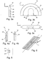
- the wire may be bent and buried by the glass fiber bundle, as is illustrated in Fig. 6 .
- the wire 3 is pressed by the applied insulating material to one side and is subsequently covered with further insulation material 7.
- a T-shaped handling tool for the purpose of continuous winding a conductor onto a coil body.
- the tool is placed onto a coil body and one end of the conductor is fixed to the coil body before winding the conductor wire.
- a wing of the tool which has a curved and tapered blade is used to direct the wire on the respective side of the wing in order to allow the continuous winding. After conductor winding the handling tool has to be removed by breaking of the wing.
- US 3979615 discloses a conductor clamping tool consisting of an iron sheet which is bent square like for clamping ends of a coil winding of a motor to lead-in wires of a connector. One end of the iron sheet having a V- shaped wire receiving slot with tapered blade edges in between the inserted lead wire is clamped. In this way the end of the coil winding is electrically connectable to the lead-in wire.
- the conductor handling tool has a curved plate-shaped tool body.
- plate-shaped means that the tool body defines a plane, so that the tool body's thickness in a direction orthogonal to the plane is smaller than the (maximal) extension of the tool body in any direction within the plane.
- the tool body comprises a conductor receiving opening for receiving a conductor portion therein and for holding the conductor portion received therein.
- an edge of the plate-shaped tool body is convex and shaped as a tapered blade edge extending essentially within a y-z-plane, i.e. these directions are defined by the plane in which the blade edge extends.
- the x-, y- and z-direction are mutually orthogonal.
- the tapered blade edge is directed away from the conductor receiving opening and forms an outer circumferential portion of the tool body for the purpose of splitting a portion of an insulating material which is applied during winding of the insulating material to an electrical coil.
- the conductor receiving opening is a wire receiving slit.
- a method of producing an electrical coil wherein the electrical coil comprises a conductor portion protruding from the electrical device portion.
- the method comprises:
- the method further comprises removing the conductor handling tool from the conductor portion after splitting the tape portion.
- the electrical device is an electric coil, and the electrically insulating material is applied by winding the electrically insulating material around the coil.
- the protruding conductor portion may be wire or a connection flag.
- the tape of electrically insulating material is a tape having unidirectional fibers, e.g. a prepreg tape.
- the tape is wound with the fibers extending essentially in the direction of the blade edge so that the tape is split by the blade edge essentially along the direction of the fibers. In this case the spreading may be performed without cutting a substantial number of fibers, thus increasing the stability of the insulating layer.
- the conductor handling tool is a tool described in any other part of this document.
- the conductor handling tool and the method described herein enhances the stability of the wire during application of the insulating layer and, in particular, may prevent wire ends to be deformed by the insulating material.
- This advantage is especially important for thin wires with a diameter up to approx. 6 mm or at least up to 4 mm, as the stability of these wires is especially low.
- a diameter shall refer to the largest cross-sectional extension in the cross-sectional plane perpendicular to the lengthwise wire extension. So, for example for a wire having a quadratic cross-section, the diameter is the length of the diagonal.
- the slit diameter is defined as the largest cross-sectional extension of the slit, wherein the slit is within an enveloping surface of the tool body).
- the tool and the method are also applicable to conductors and outside connections other than wires like e.g. aluminum or copper flags.
- a further advantage is obtained by the blade edge, which allows reliable spreading of insulating material (e.g. prepreg tape) at a random tape position. Thereby, the displacement or bending of wire during its stacking through the prepreg is reduced.
- insulating material e.g. prepreg tape
- Another advantage is that due to the tapered blade edge, the amount of insulating material being deposited on top (outside end) of the conductor (e.g. the connection flag) is reduced. Without the conductor handling tool, some of the insulating material would stay on the top of the flag, due to the flag's top surface being flat and having a thickness of sometimes up to 6mm or even more. In contrast, according to aspects of the invention, thanks to the sharp blade edge almost all of the insulating material can slide along the tool body instead of being deposited on top of the flag.
- a first embodiment of a conductor handling tool will be described.
- the conductor handling tool is shown in respective side views from the y direction ( Fig. 1a ), from the x direction ( Fig. 1b ), and from the z direction ( Fig. 1c ).
- respective directions x, y and z are indicated in each of the Figures. These directions are orthogonal with respect to each other.
- the conductor handling tool has a tool body 10, a conductor receiving opening 20 (formed as a slit 26 with two open ends 22, 24) and a tapered blade edge 12, which extends in a plane.
- the above directions x, y and z are defined such that the plane in which the blade edge 12 extends is the y-z plane.
- the tool body 10 is shaped as a plate, with its extension in one direction (the x direction) being smaller than its extension in the other directions (the y and z directions).
- the plate has a semi-circular shape.
- the tapered blade edge 12, to be described in more detail below, is arranged at the semi-circularly bent side of the tool body 10. Opposite to the blade edge 12, there is a base side of the tool body 10.
- Figs. 1a to 1c illustrate some general aspects relating to the tool body 10.
- the thickness (extension in the x direction) of the tool body 10 is determined by the diameter of the wire to be inserted, in addition to the material required to hold the tapered blade edge. It is a general aspect that the extension in the x direction is less than half, more preferably less than a third or a fifth or even a tenth of the extension in any of the other orthogonal directions y and z. It is another general aspect that the tool body 10 has a cross section in a x-y plane, the cross-section having a y:x aspect ratio of at least 3:1, or of at least 5:1 or even of at least 10:1.
- the y:x aspect ratio is defined as the maximum extension of the cross-section in the y direction divided by the maximum extension of the cross-section in the x direction.
- the height of the tool body in z direction is at least two times or five times the width of the conductor receiving opening 20.
- a tool body with height in z direction of merely two times the width of the conductor receiving opening 20 could be constructed similarly to the tool body 10 shown in Figs. 1a to 1c , but with the conductor receiving opening 20 being arranged close to the base so that the inner support portion 14 takes very little height, and also with an obtuse-angled blade edge 12 having a blade angle of more than 45°, thus talking very little height.
- the height of such an embodiment may be as little as 2 mm (for a conductor receiving opening 20 having a width of, say, 1 mm).
- other embodiments e.g.
- the height may generally be at least 5 mm, or at least 2 cm, or even at least 5 cm. Further, the height of the tool body in z direction is generally no more than 20 cm, or even no more than 10 cm.
- the tool body 10 can be made of any material like plastic, metal, ceramics etc., and in particular may be made of an insulating material such as plastic. Further, the tool body 10 is rigid, such that it defines an essentially fixed spatial relation between the conductor receiving opening 20 and the blade edge 12. In some embodiments, the tool body has at least a surface that comprises a non-sticking material such as PTFE. Further, it is preferred that the tool body is integrally made of one piece.
- the conductor receiving opening 20 is shaped for receiving a conductor portion therein.
- the conductor receiving opening 20 is formed as a wire receiving slit for receiving the wire sideways therein, and for holding the wire portion received therein.
- the slit 26 extends within the y-z plane, or more precisely within a plane that is parallel to the y-z-plane (here, the term parallel plane may also refer to the y-z-plane, since the y-z-plane is parallel to itself).
- the slit 26 is open to one side, such that the wire can be inserted into the slit 26 from the side.
- the wire receiving slit 26 has a first open end 22 and a second open end 24 for receiving an intermediate wire section in the slit 26 between these ends 22 and 24. These open ends are located at the base side of the tool body 10, opposite to the blade edge 12.
- the conductor receiving opening 20 (here, the slit 26), should be dimensioned such that the maximum extension of the tool body 10 in the x direction is less than four times, or even less than twice, or even less than 1.5 times, the maximum wire diameter of a circular wire fitting in the conductor receiving opening 20 (as can be seen e.g. in Fig. 1c , the maximum wire diameter corresponding essentially to the lateral dimension in x direction of the ends 22 and 24 of the conductor receiving opening). It is another general aspect that the conductor receiving opening 20 should be dimensioned such that the maximum extension of the tool body 10 in the x direction is less than four times the maximum extension of the conductor receiving opening 20 in the x direction.
- the wire receiving slit 26 generally has a cross-sectional diameter (in a plane orthogonal to the slit extension) of more than 1 mm. Further, the wire receiving slit generally has a cross-sectional diameter of less than 8 mm.
- the tapered blade edge 12 extends essentially within the y-z-plane (actually this defines the y-z plane) and is directed away from the conductor receiving opening 20. This means that in the y-z-plane, the blade edge cutting side is facing away from the projection of the conductor receiving opening 20 onto the y-z-plane (as seen in Fig. 1b ).
- the tapered blade edge has a blade angle which can be seen in Fig. 1a .
- the blade angle is defined as the angle of the blade edge in a cross-sectional surface normal to the blade edge. The sharper the edge, the easier the spreading, if the blade edge is stable enough. Even an angle of 89° would be possible.
- the tapered blade edge has a blade angle of less than 30°, or even less than 20°.
- the tapered blade edge 12 forms an outer circumferential portion of the tool body 10 which is convex shaped (see Fig. 1b ).
- the conductor receiving opening 20 comprises a slit 26 forming an intermediate portion of the tool body 10.
- all these portions have semicircular shape. However, they may alternatively have any other shape, e.g. any bent shape.
- the blade edge is bent within the y-z plane.
- the blade edge is shown as a semicircle.
- other circular segments or, still more generally, curved shapes are also possible.
- both the blade edge and the slit 26 of the conductor receiving opening 20 have a semicircular shape. It is a general aspect that the blade edge runs along the slit 26 of the conductor receiving opening 20, irrespective of their shape.
- the tool body 10 has a base, formed at the side of the plate that is opposite to the blade edge 12.
- the base side is adapted to contact the electrical device portion during operation. Therefore, the open ends 22 and 24 of the conductor receiving opening 20 are located at the base side.
- the conductor receiving opening 20 extends to the base side of the tool body 10. Further, the open ends 22 and 24 end at the base side at an essentially right angle. This allows for the wires portions to be inserted in the ends 22 and 24 in parallel to one another. Other positions, e.g. having a different angle, are also possible. The position depends on the equipment and on the conductor.
- the base side is straight and extends parallel to the y direction.
- the base side can have a shape that is adapted to the shape of the electric device portion, e.g. be inwardly curved in the shape of a circular segment matching the bent surface of the coil portion.
- the base side can be tapered at least partially, so that e.g. prepreg fibers split by the tool body 10 can be brought in close proximity to the connector 3.
- the electrical device is a transformator coil 1.
- the coil has windings of electrically conductive wires (e.g. copper).
- the transformer coil 1 comprises connectors 3 (here, ends or intermediate portions of the coil wire) protruding from a coil portion of the transformer coil 1.
- the connectors 3 Prior to the step shown in Fig. 2a , the connectors 3 have already been inserted into the conductor receiving section of the tool body 10.
- the tool body 10 is the tool body shown in Figs. 1a to 1c and described above.
- the connectors 3 are inserted into the slit 26 of the tool body 10 such that a tapered blade edge 12 of the conductor handling tool is directed away from the connector 3 (see also Fig. 1b ).
- the insulating material is applied onto the coil portion in the form of an insulating tape 5 which is wound onto the coil by turning the coil on a mandrel.
- the tape 5 is a unidirectional prepreg tape with fibers, e.g. glass fibers, extending along the tape direction, and with a pre-cured solid resin.
- the insulating material tape or fabric has a width of between about 5 mm and about 600 mm.
- insulating material can be provided.
- a prepreg in the shape of a tow (tow preg), or an impregnated woven fabric can be used.
- the insulating material may comprise dry filaments (dry filament winding), but in some cases also wet filaments (wet filament winding).
- a portion thereof (here: of the prepreg tape 5) is split reliably by the blade edge of the tool body 10.
- Fig. 2a shows the situation prior to the tape 5 being split. Then, as shown in Fig. 2b , the tape 5 is split and spread along the direction of the fibers such that the fibers slide along the sides of the tool body 10 (one part of the tape 5 on each side of the tool body 10).
- the fibers from each side subsequently approach each other after having slid past the tool body 10, due to the tension of the tape 5 and more importantly due to the favorable small lateral extension in x direction of the tool body 10. It is preferred that the tape 5 slides completely past the tool body 10. Then, the tape 5 is able to encapsulate the connector 3 ( Fig. 2c ) tightly. Therefore, in the final insulating layer that is finally created from the prepreg tape 5, the glass fibers are still under tension and there is almost no resin rich region generated in x direction (sideways) adjacent to the connector 3, and only a little resin rich region in y direction (lengthwise in the direction of the fibers) adjacent to the connector 3.
- Figs. 3a to 3c show a second embodiment of a conductor handling tool in respective side views from the y, x, and z direction, respectively.
- Figs. 3a and 3c correspond to Figs. 1a to 1c , and same or similar elements are designated by the same reference numbers. In the following, only the differences with respect to the first embodiment ( Figs. 1a to 1c ) will be described.
- the conductor receiving opening 20 is formed as a slot 28 having one open end 29 (instead of being a slit 26 as in the first embodiment, see Fig. 1b ).
- the conductor receiving opening, or slot 28 is form-fit to the shape of a coil connection flag for receiving the coil connection flag therein.
- “form-fit” means that the slot 28 is dimensioned such that a main portion of the flag can be inserted therein, and that the slot 28 is adapted to the contour of the flag such that the inserted portion is held therein by the shape of the slot 28.
- the slot 28 is closed (left and right of the slot 28 in Fig. 3a ) by two solid side faces essentially parallel to a z-y plane, so that when the connection flag is inserted from the open end 29, it is stably held by the side faces.
- the slot 28 is form-fit to the shape of a coil connection flag having the dimensions xx. More generally, the slot has preferably a height in z direction between 30 mm and 100 mm, a width in y direction between 20 mm and 50 mm, and a depth in x direction between 3 mm and 10 mm.
- the shape of the tool body 10 and in particular of the blade edge 12 in the y-z plane is shown to be semi-circular. However, while this shape is advantageous, other shapes may be used as well.
- the shape of the blade in the y-z plane may be adapted to the contour of the conductor receiving opening 20 (i.e. here, to the contour of the slot 28), or have any other shape.
- the conductor handling tool may further comprise a conductor fixation arrangement adapted to cooperate with the conductor receiving opening for fixating the conductor received in the conductor receiving opening.
- the conductor fixation arrangement can be e.g. a closing lid, a cover, or a resilient element.
- Figs. 4a and 4b show a third embodiment of a conductor handling tool having such a conductor fixation arrangement in a cross-sectional side view from the y direction.
- the third embodiment is similar to the first embodiment, and same or similar elements are designated by the same reference numbers.
- the conductor receiving opening is formed as a slit 26 having an open side.
- a cover 30 adapted for closing the open side of the slit 26.
- the cover 30 has a sliding guide 32 allowing the cover to slide along a surface of the tool body 10 between an open position (with the side of the slit 26 being open, shown in Fig. 4a ), and a closed position (with the side of the slit 26 being closed, shown in Fig. 4b ).
- the sliding guide 32 can be e.g. a track fixated at the cover 30 and engaging in a groove at the tool body 10 that allows sliding in the z direction, but fixates the other directions.
- the cover 30 has a double advantage. Firstly, when the cover 30 is closed as in Fig. 4b , it serves as a conductor fixation arrangement, because it cooperates with the slit 26 for fixating the conductor received in the slit 26. Secondly, it allows for a smooth outside surface when closed, such as to facilitate sliding of the insulating material past the tool body 10. To this purpose, the cover 30 may comprise an anti-sticking surface such as PTFE.
- any other fastening means of fastening the cover 30 to the tool body 10 can be provided, such as a hinge connection, a lock, a snap-on connection etc.
- Fig. 5 show a detail of a conductor receiving opening in a cross-sectional side view from the y direction.
- the conductor receiving opening is a wire receiving slit 26 as in embodiment 1.
- two resilient elements 27 are provided as conductor fixation arrangement within the wire receiving slit 26.
- the two resilient elements can be e.g. rubber elements such as rubber tubes extending along the slit 26 or along a portion of the slit 26. Generally, only one resilient element or a plurality of resilient elements may be found suitable for fixating the conductor.
- the conductor handling tool can be modified in other ways not described above, without departing from the scope as defined in the patent claims.
- the conductor receiving opening may be a first conductor receiving opening, namely e.g. a wire receiving slit; and the tool may further comprise a second conductor receiving opening, e.g. a slot form-fit to the shape of a coil connection flag for receiving the coil connection flag therein.
- two conductor receiving openings are provided, the first one being e.g. a slit 26 as described with respect to Figs. 1a-1c , and the second one being e.g. a slot 28 as described with respect to Figs. 3a to 3c .
- a multi-purpose tool is obtained which is adapted to a plurality of different conductors.
- a base surface of the tool i.e. the surface adapted for being in contact with the electrical device
- the base surface may be curved inwardly in the case of the electrical device being a wire coil, such as to be adapted to the coil curvature of the wire coil.
Claims (14)
- Verfahren zum Herstellen einer elektrischen Spule (1), wobei die elektrische Spule (1) einen Leiterabschnitt (3) umfasst, wobei das Verfahren die folgenden Schritte umfasst:- Aufwickeln eines Drahtes auf eine rohe Spule (1) ;- Bereitstellen mindestens des einen Leiterabschnitts (3), der von der rohen Spule (1) hervorsteht, wobei der Leiterabschnitt (3) ein elektrischer Anschluss ist;- Einsetzen des elektrischen Anschlusses (3) in einen Leiteraufnahmeabschnitt (20) eines Leiterhandhabungswerkzeugs, das einen gekrümmten, plattenförmigen Werkzeugkörper (10) aufweist, derart, dass eine spitz zulaufende Schneidkante (12) des Werkzeugkörpers (10) von dem Leiterabschnitt (3) weggerichtet ist;- Aufwickeln eines Bandes aus einem elektrisch isolierenden Material (5) auf mindestens einen Abschnitt der rohen Spule (1);- Aufteilen eines Bandabschnittes des Bandes durch die Schneidkante (12) und- Entfernen des Leiterhandhabungswerkzeugs aus dem Leiterabschnitt (3) nach dem Aufteilen.
- Verfahren nach Anspruch 1, wobei das Band des elektrisch isolierenden Materials ein Band mit einseitig gerichteten Fasern ist und wobei das Band an der elektrischen Vorrichtung in der Weise angebracht ist, dass sich die Fasern im Wesentlichen in die Richtung der Schneidkante erstrecken, so dass das Band im Wesentlichen entlang der Richtung der Fasern aufgeteilt wird.
- Verfahren zum Herstellen eines Transformators, das Folgendes umfasst:- Herstellen einer ersten elektrischen Spule nach Anspruch 1;- Herstellen einer zweiten elektrischen Spule nach Anspruch 1;- Bereitstellen eines Transformatorgehäuses; und- Anordnung der ersten elektrischen Spule und der zweiten elektrischen Spule in dem Transformatorgehäuse, so dass die erste elektrische Spule und die zweite elektrische Spule induktiv gekoppelt sind.
- Leiterhandhabungswerkzeug mit einem gekrümmten, plattenförmigen Werkzeugkörper (10), wobei der Werkzeugkörper (10) eine Leiteraufnahmeöffnung (20) umfasst, um darin einen Leiterabschnitt (3) aufzunehmen und um den darin aufgenommenen Leiterabschnitt festzuhalten, und wobei eine Kante des plattenförmigen Werkzeugkörpers (10) als eine spitz zulaufende Schneidkante (12) geformt ist, die sich im Wesentlichen innerhalb einer y-z-Ebene erstreckt, die von der Leiteraufnahmeöffnung (20) weggerichtet ist, und die spitz zulaufende Schneidkante (12) einen konvexen äußeren Umfangsabschnitt des Werkzeugkörpers (10) bildet, um einen Abschnitt des Isoliermaterials während einer Aufwicklung des Isoliermaterials aufzuteilen.
- Leiterhandhabungswerkzeug nach Anspruch 4, wobei sich die Leiteraufnahmeöffnung (20) im Wesentlichen innerhalb einer Ebene erstreckt, die parallel zu der y-z-Ebene ist.
- Leiterhandhabungswerkzeug nach einem der Ansprüche 4 bis 5, wobei der Werkzeugkörper (10) einen Querschnitt in einer x-y-Ebene aufweist, wobei der Querschnitt ein y:x-Aspektverhältnis von mindestens 2:1 aufweist, in Ausführungsformen mindestens 3:1.
- Leiterhandhabungswerkzeug nach einem der Ansprüche 4 bis 6, wobei der Werkzeugkörper einteilig aus einem Stück hergestellt ist.
- Leiterhandhabungswerkzeug nach einem der Ansprüche 4 bis 7, wobei die Schneidkante als ein Kreissegment geformt ist, insbesondere als ein Halbkreissegment, das in der y-z-Ebene gekrümmt ist.
- Leiterhandhabungswerkzeug nach einem der Ansprüche 4 bis 8, wobei die Leiteraufnahmeöffnung als ein Drahtaufnahmeschlitz geformt ist, um darin die Drahtseitenwege aufzunehmen.
- Leiterhandhabungswerkzeug nach Anspruch 9, wobei der Drahtaufnahmeschlitz ein erstes offenes Ende (22) und ein zweites offenes Ende (24) aufweist, um einen Zwischendrahtabschnitt dazwischen aufzunehmen, wobei das erste offene Ende (22) und das zweite offene Ende (24) auf einer Grundseite des Werkzeugkörpers (10) gegenüber der Schneidkante (12) angeordnet ist.
- Leiterhandhabungswerkzeug nach einem der Ansprüche 9 bis 10, wobei der Drahtaufnahmeschlitz einen Querschnittsdurchmesser von weniger als 6 mm aufweist.
- Leiterhandhabungswerkzeug nach einem der Ansprüche 4 bis 11, das ferner eine Leiterbefestigungsanordnung umfasst, um mit der Leiteraufnahmeöffnung zur Fixierung des Leiters, der in der Leiteraufnahmeöffnung aufgenommen worden ist, zusammenzuwirken.
- Leiterhandhabungswerkzeug nach einem der Ansprüche 4 bis 12, wobei die Leiteraufnahmeöffnung an die Form einer Spulenanschlussfahne formangepasst ist, um die Spulenanschlussfahne aufzunehmen.
- Verfahren nach einem der Ansprüche 1 bis 3, wobei das Leiterhandhabungswerkzeug ein Leiterhandhabungswerkzeug nach einem der Ansprüche 4 bis 13 ist.
Priority Applications (2)
| Application Number | Priority Date | Filing Date | Title |
|---|---|---|---|
| EP10734724.7A EP2454744B1 (de) | 2009-07-15 | 2010-07-09 | Leiterhandhabungswerkzeug und verfahren zur anwendung eines elektrisch isolierenden materials |
| PL10734724T PL2454744T3 (pl) | 2009-07-15 | 2010-07-09 | Narzędzie manipulujące przewodem i sposób nakładania materiału izolującego elektrycznie |
Applications Claiming Priority (3)
| Application Number | Priority Date | Filing Date | Title |
|---|---|---|---|
| EP09165562 | 2009-07-15 | ||
| PCT/EP2010/059882 WO2011006845A1 (en) | 2009-07-15 | 2010-07-09 | Conductor handling tool and a method of applying an electrically insulating material |
| EP10734724.7A EP2454744B1 (de) | 2009-07-15 | 2010-07-09 | Leiterhandhabungswerkzeug und verfahren zur anwendung eines elektrisch isolierenden materials |
Publications (2)
| Publication Number | Publication Date |
|---|---|
| EP2454744A1 EP2454744A1 (de) | 2012-05-23 |
| EP2454744B1 true EP2454744B1 (de) | 2013-04-17 |
Family
ID=41508779
Family Applications (1)
| Application Number | Title | Priority Date | Filing Date |
|---|---|---|---|
| EP10734724.7A Not-in-force EP2454744B1 (de) | 2009-07-15 | 2010-07-09 | Leiterhandhabungswerkzeug und verfahren zur anwendung eines elektrisch isolierenden materials |
Country Status (6)
| Country | Link |
|---|---|
| US (1) | US20120222292A1 (de) |
| EP (1) | EP2454744B1 (de) |
| CN (1) | CN102473518B (de) |
| BR (1) | BR112012001067A2 (de) |
| PL (1) | PL2454744T3 (de) |
| WO (1) | WO2011006845A1 (de) |
Families Citing this family (1)
| Publication number | Priority date | Publication date | Assignee | Title |
|---|---|---|---|---|
| CN105351797B (zh) * | 2015-10-14 | 2018-07-27 | 崇义县精亿灯饰制品有限公司 | 一种藤蔓灯及其制作方法 |
Family Cites Families (14)
| Publication number | Priority date | Publication date | Assignee | Title |
|---|---|---|---|---|
| US3979615A (en) * | 1975-02-05 | 1976-09-07 | Amp Incorporated | Field assembly for electric motors |
| US4110903A (en) * | 1976-11-05 | 1978-09-05 | Vwnding Components, Inc. | Method of making induction coils |
| US4173593A (en) * | 1977-04-05 | 1979-11-06 | Westinghouse Electric Corp. | Metal acetylacetonate latent accelerators for an epoxy-styrene resin system |
| US4161737A (en) * | 1977-10-03 | 1979-07-17 | Albright Eugene A | Helical antenna |
| JPS54136653A (en) * | 1978-04-14 | 1979-10-23 | Tokyo Shibaura Electric Co | Winding apparatus |
| US4160178A (en) * | 1978-06-01 | 1979-07-03 | Westinghouse Electric Corp. | Method of coating an article with a solventless acrylic epoxy impregnating composition curable in a gas atmosphere without heat |
| US4442138A (en) * | 1982-02-22 | 1984-04-10 | Westinghouse Electric Corp. | Substrate pretreatment with a metal-beta keto ester complex in the method of curing an anaerobic resin |
| DE3836139A1 (de) * | 1988-03-16 | 1989-10-05 | Johann Lasslop | Halterung zum befestigen des drahtanfanges beim bewickeln von ringkernen einer ringkernspule |
| JP2593101B2 (ja) * | 1990-06-08 | 1997-03-26 | サンケン電気株式会社 | コイル装置 |
| US5619176A (en) * | 1995-12-21 | 1997-04-08 | Square D Company | System for coupling external leads to a multitap transformer |
| US6489701B1 (en) * | 1999-10-12 | 2002-12-03 | American Superconductor Corporation | Superconducting rotating machines |
| WO2002027736A1 (en) * | 2000-09-27 | 2002-04-04 | Igc-Superpower, Llc | Low alternating current (ac) loss superconducting coils |
| TWI291183B (en) * | 2003-12-26 | 2007-12-11 | Delta Electronics Inc | Transformer structure |
| DE102007017702A1 (de) * | 2007-04-14 | 2008-10-16 | Abb Technology Ag | Elektrisches Bauteil mit Wicklung und Anzapfung |
-
2010
- 2010-07-09 EP EP10734724.7A patent/EP2454744B1/de not_active Not-in-force
- 2010-07-09 WO PCT/EP2010/059882 patent/WO2011006845A1/en active Application Filing
- 2010-07-09 PL PL10734724T patent/PL2454744T3/pl unknown
- 2010-07-09 BR BR112012001067A patent/BR112012001067A2/pt not_active IP Right Cessation
- 2010-07-09 CN CN201080032400.0A patent/CN102473518B/zh not_active Expired - Fee Related
-
2012
- 2012-01-05 US US13/344,225 patent/US20120222292A1/en not_active Abandoned
Also Published As
| Publication number | Publication date |
|---|---|
| WO2011006845A1 (en) | 2011-01-20 |
| PL2454744T3 (pl) | 2013-09-30 |
| CN102473518A (zh) | 2012-05-23 |
| BR112012001067A2 (pt) | 2019-09-24 |
| CN102473518B (zh) | 2014-05-07 |
| US20120222292A1 (en) | 2012-09-06 |
| EP2454744A1 (de) | 2012-05-23 |
Similar Documents
| Publication | Publication Date | Title |
|---|---|---|
| US4550220A (en) | Splice insulator assembly | |
| US10032544B2 (en) | Terminal treatment apparatus for a coaxial cable to separate a sheath from a conductor | |
| CN107004963B (zh) | 带有屏蔽的插塞式连接器 | |
| US9240662B2 (en) | Terminal treatment method and terminal treatment apparatus for coaxial cable | |
| EP2330705B1 (de) | Drahthalter und drahtbündelungsstruktur | |
| CN101183755A (zh) | 具有改进的电缆卡的插塞接头 | |
| CN107112644A (zh) | 插塞式连接器 | |
| US20170264148A1 (en) | Tool and method for use in assembling a stator assembly of an electric machine | |
| US5445535A (en) | Insulation displacement terminal | |
| CN105551583B (zh) | 扁立线圈用扁平绝缘电线及其制造方法 | |
| US10957465B2 (en) | Wire harness with sewing and manufacturing method of wire harness | |
| US9276452B2 (en) | Method for manufacturing winding coil for an electrical machine | |
| EP2454744B1 (de) | Leiterhandhabungswerkzeug und verfahren zur anwendung eines elektrisch isolierenden materials | |
| KR20130039327A (ko) | 절연 전선의 연결 구조 및 연결 방법 | |
| CA2919284C (en) | Electrical connectors and related methods | |
| KR101020828B1 (ko) | 와이어를 연결하기 위한 장치 및, 방법 | |
| JPH07109777B2 (ja) | 絶縁被覆ワイヤ接続装置 | |
| CN110718999A (zh) | 电机定子夹具及具有其的电机定子生产设备 | |
| US11482843B2 (en) | Process of manufacturing an electrical wiring assembly and electrical wiring assembly manufactured by said process | |
| US20020028598A1 (en) | Electrical connection device | |
| KR200403080Y1 (ko) | 절연테이프 절단장치 | |
| EP3855603A1 (de) | Elastisch verriegelnder wicklungsträger für vorgeformte spulenanordnungen eines elektromotors | |
| KR102067588B1 (ko) | 전선 결합용 연결구 | |
| KR101781578B1 (ko) | 권선 커플러용 절연 패드 | |
| KR101175552B1 (ko) | 와이어 연결장치 |
Legal Events
| Date | Code | Title | Description |
|---|---|---|---|
| PUAI | Public reference made under article 153(3) epc to a published international application that has entered the european phase |
Free format text: ORIGINAL CODE: 0009012 |
|
| 17P | Request for examination filed |
Effective date: 20111220 |
|
| AK | Designated contracting states |
Kind code of ref document: A1 Designated state(s): AL AT BE BG CH CY CZ DE DK EE ES FI FR GB GR HR HU IE IS IT LI LT LU LV MC MK MT NL NO PL PT RO SE SI SK SM TR |
|
| DAX | Request for extension of the european patent (deleted) | ||
| REG | Reference to a national code |
Ref country code: DE Ref legal event code: R079 Ref document number: 602010006426 Country of ref document: DE Free format text: PREVIOUS MAIN CLASS: H01F0041100000 Ipc: H01F0041060000 |
|
| GRAP | Despatch of communication of intention to grant a patent |
Free format text: ORIGINAL CODE: EPIDOSNIGR1 |
|
| RIC1 | Information provided on ipc code assigned before grant |
Ipc: H01F 41/06 20060101AFI20121031BHEP Ipc: H01F 27/29 20060101ALI20121031BHEP Ipc: H01F 41/10 20060101ALI20121031BHEP |
|
| GRAS | Grant fee paid |
Free format text: ORIGINAL CODE: EPIDOSNIGR3 |
|
| GRAA | (expected) grant |
Free format text: ORIGINAL CODE: 0009210 |
|
| AK | Designated contracting states |
Kind code of ref document: B1 Designated state(s): AL AT BE BG CH CY CZ DE DK EE ES FI FR GB GR HR HU IE IS IT LI LT LU LV MC MK MT NL NO PL PT RO SE SI SK SM TR |
|
| REG | Reference to a national code |
Ref country code: GB Ref legal event code: FG4D |
|
| REG | Reference to a national code |
Ref country code: CH Ref legal event code: EP |
|
| REG | Reference to a national code |
Ref country code: IE Ref legal event code: FG4D |
|
| REG | Reference to a national code |
Ref country code: AT Ref legal event code: REF Ref document number: 607756 Country of ref document: AT Kind code of ref document: T Effective date: 20130515 |
|
| REG | Reference to a national code |
Ref country code: DE Ref legal event code: R096 Ref document number: 602010006426 Country of ref document: DE Effective date: 20130613 |
|
| REG | Reference to a national code |
Ref country code: AT Ref legal event code: MK05 Ref document number: 607756 Country of ref document: AT Kind code of ref document: T Effective date: 20130417 |
|
| REG | Reference to a national code |
Ref country code: LT Ref legal event code: MG4D |
|
| REG | Reference to a national code |
Ref country code: PL Ref legal event code: T3 |
|
| REG | Reference to a national code |
Ref country code: NL Ref legal event code: VDEP Effective date: 20130417 |
|
| PG25 | Lapsed in a contracting state [announced via postgrant information from national office to epo] |
Ref country code: PT Free format text: LAPSE BECAUSE OF FAILURE TO SUBMIT A TRANSLATION OF THE DESCRIPTION OR TO PAY THE FEE WITHIN THE PRESCRIBED TIME-LIMIT Effective date: 20130819 Ref country code: BE Free format text: LAPSE BECAUSE OF FAILURE TO SUBMIT A TRANSLATION OF THE DESCRIPTION OR TO PAY THE FEE WITHIN THE PRESCRIBED TIME-LIMIT Effective date: 20130417 Ref country code: SI Free format text: LAPSE BECAUSE OF FAILURE TO SUBMIT A TRANSLATION OF THE DESCRIPTION OR TO PAY THE FEE WITHIN THE PRESCRIBED TIME-LIMIT Effective date: 20130417 Ref country code: IS Free format text: LAPSE BECAUSE OF FAILURE TO SUBMIT A TRANSLATION OF THE DESCRIPTION OR TO PAY THE FEE WITHIN THE PRESCRIBED TIME-LIMIT Effective date: 20130817 Ref country code: AT Free format text: LAPSE BECAUSE OF FAILURE TO SUBMIT A TRANSLATION OF THE DESCRIPTION OR TO PAY THE FEE WITHIN THE PRESCRIBED TIME-LIMIT Effective date: 20130417 Ref country code: ES Free format text: LAPSE BECAUSE OF FAILURE TO SUBMIT A TRANSLATION OF THE DESCRIPTION OR TO PAY THE FEE WITHIN THE PRESCRIBED TIME-LIMIT Effective date: 20130728 Ref country code: NO Free format text: LAPSE BECAUSE OF FAILURE TO SUBMIT A TRANSLATION OF THE DESCRIPTION OR TO PAY THE FEE WITHIN THE PRESCRIBED TIME-LIMIT Effective date: 20130717 Ref country code: GR Free format text: LAPSE BECAUSE OF FAILURE TO SUBMIT A TRANSLATION OF THE DESCRIPTION OR TO PAY THE FEE WITHIN THE PRESCRIBED TIME-LIMIT Effective date: 20130718 Ref country code: FI Free format text: LAPSE BECAUSE OF FAILURE TO SUBMIT A TRANSLATION OF THE DESCRIPTION OR TO PAY THE FEE WITHIN THE PRESCRIBED TIME-LIMIT Effective date: 20130417 Ref country code: LT Free format text: LAPSE BECAUSE OF FAILURE TO SUBMIT A TRANSLATION OF THE DESCRIPTION OR TO PAY THE FEE WITHIN THE PRESCRIBED TIME-LIMIT Effective date: 20130417 Ref country code: SE Free format text: LAPSE BECAUSE OF FAILURE TO SUBMIT A TRANSLATION OF THE DESCRIPTION OR TO PAY THE FEE WITHIN THE PRESCRIBED TIME-LIMIT Effective date: 20130417 |
|
| PG25 | Lapsed in a contracting state [announced via postgrant information from national office to epo] |
Ref country code: BG Free format text: LAPSE BECAUSE OF FAILURE TO SUBMIT A TRANSLATION OF THE DESCRIPTION OR TO PAY THE FEE WITHIN THE PRESCRIBED TIME-LIMIT Effective date: 20130717 Ref country code: HR Free format text: LAPSE BECAUSE OF FAILURE TO SUBMIT A TRANSLATION OF THE DESCRIPTION OR TO PAY THE FEE WITHIN THE PRESCRIBED TIME-LIMIT Effective date: 20130417 Ref country code: LV Free format text: LAPSE BECAUSE OF FAILURE TO SUBMIT A TRANSLATION OF THE DESCRIPTION OR TO PAY THE FEE WITHIN THE PRESCRIBED TIME-LIMIT Effective date: 20130417 Ref country code: CY Free format text: LAPSE BECAUSE OF FAILURE TO SUBMIT A TRANSLATION OF THE DESCRIPTION OR TO PAY THE FEE WITHIN THE PRESCRIBED TIME-LIMIT Effective date: 20130417 |
|
| PG25 | Lapsed in a contracting state [announced via postgrant information from national office to epo] |
Ref country code: EE Free format text: LAPSE BECAUSE OF FAILURE TO SUBMIT A TRANSLATION OF THE DESCRIPTION OR TO PAY THE FEE WITHIN THE PRESCRIBED TIME-LIMIT Effective date: 20130417 Ref country code: SK Free format text: LAPSE BECAUSE OF FAILURE TO SUBMIT A TRANSLATION OF THE DESCRIPTION OR TO PAY THE FEE WITHIN THE PRESCRIBED TIME-LIMIT Effective date: 20130417 Ref country code: CZ Free format text: LAPSE BECAUSE OF FAILURE TO SUBMIT A TRANSLATION OF THE DESCRIPTION OR TO PAY THE FEE WITHIN THE PRESCRIBED TIME-LIMIT Effective date: 20130417 Ref country code: DK Free format text: LAPSE BECAUSE OF FAILURE TO SUBMIT A TRANSLATION OF THE DESCRIPTION OR TO PAY THE FEE WITHIN THE PRESCRIBED TIME-LIMIT Effective date: 20130417 |
|
| PLBE | No opposition filed within time limit |
Free format text: ORIGINAL CODE: 0009261 |
|
| STAA | Information on the status of an ep patent application or granted ep patent |
Free format text: STATUS: NO OPPOSITION FILED WITHIN TIME LIMIT |
|
| PG25 | Lapsed in a contracting state [announced via postgrant information from national office to epo] |
Ref country code: NL Free format text: LAPSE BECAUSE OF FAILURE TO SUBMIT A TRANSLATION OF THE DESCRIPTION OR TO PAY THE FEE WITHIN THE PRESCRIBED TIME-LIMIT Effective date: 20130417 Ref country code: MC Free format text: LAPSE BECAUSE OF FAILURE TO SUBMIT A TRANSLATION OF THE DESCRIPTION OR TO PAY THE FEE WITHIN THE PRESCRIBED TIME-LIMIT Effective date: 20130417 Ref country code: RO Free format text: LAPSE BECAUSE OF FAILURE TO SUBMIT A TRANSLATION OF THE DESCRIPTION OR TO PAY THE FEE WITHIN THE PRESCRIBED TIME-LIMIT Effective date: 20130417 |
|
| 26N | No opposition filed |
Effective date: 20140120 |
|
| REG | Reference to a national code |
Ref country code: IE Ref legal event code: MM4A |
|
| REG | Reference to a national code |
Ref country code: FR Ref legal event code: ST Effective date: 20140331 |
|
| REG | Reference to a national code |
Ref country code: DE Ref legal event code: R097 Ref document number: 602010006426 Country of ref document: DE Effective date: 20140120 |
|
| PG25 | Lapsed in a contracting state [announced via postgrant information from national office to epo] |
Ref country code: FR Free format text: LAPSE BECAUSE OF NON-PAYMENT OF DUE FEES Effective date: 20130731 |
|
| PG25 | Lapsed in a contracting state [announced via postgrant information from national office to epo] |
Ref country code: IE Free format text: LAPSE BECAUSE OF NON-PAYMENT OF DUE FEES Effective date: 20130709 |
|
| REG | Reference to a national code |
Ref country code: CH Ref legal event code: PL |
|
| GBPC | Gb: european patent ceased through non-payment of renewal fee |
Effective date: 20140709 |
|
| PG25 | Lapsed in a contracting state [announced via postgrant information from national office to epo] |
Ref country code: LI Free format text: LAPSE BECAUSE OF NON-PAYMENT OF DUE FEES Effective date: 20140731 Ref country code: CH Free format text: LAPSE BECAUSE OF NON-PAYMENT OF DUE FEES Effective date: 20140731 |
|
| PG25 | Lapsed in a contracting state [announced via postgrant information from national office to epo] |
Ref country code: SM Free format text: LAPSE BECAUSE OF FAILURE TO SUBMIT A TRANSLATION OF THE DESCRIPTION OR TO PAY THE FEE WITHIN THE PRESCRIBED TIME-LIMIT Effective date: 20130417 Ref country code: GB Free format text: LAPSE BECAUSE OF NON-PAYMENT OF DUE FEES Effective date: 20140709 |
|
| PG25 | Lapsed in a contracting state [announced via postgrant information from national office to epo] |
Ref country code: TR Free format text: LAPSE BECAUSE OF FAILURE TO SUBMIT A TRANSLATION OF THE DESCRIPTION OR TO PAY THE FEE WITHIN THE PRESCRIBED TIME-LIMIT Effective date: 20130417 Ref country code: MT Free format text: LAPSE BECAUSE OF FAILURE TO SUBMIT A TRANSLATION OF THE DESCRIPTION OR TO PAY THE FEE WITHIN THE PRESCRIBED TIME-LIMIT Effective date: 20130417 |
|
| PG25 | Lapsed in a contracting state [announced via postgrant information from national office to epo] |
Ref country code: MK Free format text: LAPSE BECAUSE OF FAILURE TO SUBMIT A TRANSLATION OF THE DESCRIPTION OR TO PAY THE FEE WITHIN THE PRESCRIBED TIME-LIMIT Effective date: 20130417 Ref country code: HU Free format text: LAPSE BECAUSE OF FAILURE TO SUBMIT A TRANSLATION OF THE DESCRIPTION OR TO PAY THE FEE WITHIN THE PRESCRIBED TIME-LIMIT; INVALID AB INITIO Effective date: 20100709 Ref country code: LU Free format text: LAPSE BECAUSE OF NON-PAYMENT OF DUE FEES Effective date: 20130709 |
|
| PGFP | Annual fee paid to national office [announced via postgrant information from national office to epo] |
Ref country code: PL Payment date: 20150624 Year of fee payment: 6 |
|
| PGFP | Annual fee paid to national office [announced via postgrant information from national office to epo] |
Ref country code: DE Payment date: 20150721 Year of fee payment: 6 |
|
| PGFP | Annual fee paid to national office [announced via postgrant information from national office to epo] |
Ref country code: IT Payment date: 20150727 Year of fee payment: 6 |
|
| REG | Reference to a national code |
Ref country code: DE Ref legal event code: R119 Ref document number: 602010006426 Country of ref document: DE |
|
| PG25 | Lapsed in a contracting state [announced via postgrant information from national office to epo] |
Ref country code: DE Free format text: LAPSE BECAUSE OF NON-PAYMENT OF DUE FEES Effective date: 20170201 |
|
| PG25 | Lapsed in a contracting state [announced via postgrant information from national office to epo] |
Ref country code: IT Free format text: LAPSE BECAUSE OF NON-PAYMENT OF DUE FEES Effective date: 20160709 |
|
| PG25 | Lapsed in a contracting state [announced via postgrant information from national office to epo] |
Ref country code: PL Free format text: LAPSE BECAUSE OF NON-PAYMENT OF DUE FEES Effective date: 20160709 |
|
| PG25 | Lapsed in a contracting state [announced via postgrant information from national office to epo] |
Ref country code: AL Free format text: LAPSE BECAUSE OF FAILURE TO SUBMIT A TRANSLATION OF THE DESCRIPTION OR TO PAY THE FEE WITHIN THE PRESCRIBED TIME-LIMIT Effective date: 20130417 |