EP2454518B1 - Verfahren zur vergasung eines flüssigen kohlenwasserstoffstroms und gerät dafür - Google Patents
Verfahren zur vergasung eines flüssigen kohlenwasserstoffstroms und gerät dafür Download PDFInfo
- Publication number
- EP2454518B1 EP2454518B1 EP10730803.3A EP10730803A EP2454518B1 EP 2454518 B1 EP2454518 B1 EP 2454518B1 EP 10730803 A EP10730803 A EP 10730803A EP 2454518 B1 EP2454518 B1 EP 2454518B1
- Authority
- EP
- European Patent Office
- Prior art keywords
- stream
- hydrocarbon stream
- streams
- pressurised
- liquefied
- Prior art date
- Legal status (The legal status is an assumption and is not a legal conclusion. Google has not performed a legal analysis and makes no representation as to the accuracy of the status listed.)
- Not-in-force
Links
- 229930195733 hydrocarbon Natural products 0.000 title claims description 321
- 150000002430 hydrocarbons Chemical class 0.000 title claims description 321
- 239000004215 Carbon black (E152) Substances 0.000 title claims description 317
- 239000007788 liquid Substances 0.000 title claims description 143
- 238000000034 method Methods 0.000 title claims description 50
- 238000002309 gasification Methods 0.000 title claims description 22
- VNWKTOKETHGBQD-UHFFFAOYSA-N methane Chemical compound C VNWKTOKETHGBQD-UHFFFAOYSA-N 0.000 claims description 96
- 239000003949 liquefied natural gas Substances 0.000 claims description 62
- 239000003345 natural gas Substances 0.000 claims description 47
- 239000012530 fluid Substances 0.000 claims description 45
- 239000007789 gas Substances 0.000 claims description 36
- 238000011084 recovery Methods 0.000 claims description 27
- 238000002156 mixing Methods 0.000 claims description 8
- 238000010438 heat treatment Methods 0.000 claims description 7
- 238000009834 vaporization Methods 0.000 claims description 4
- CURLTUGMZLYLDI-UHFFFAOYSA-N Carbon dioxide Chemical compound O=C=O CURLTUGMZLYLDI-UHFFFAOYSA-N 0.000 description 23
- 238000001816 cooling Methods 0.000 description 16
- 229910002092 carbon dioxide Inorganic materials 0.000 description 12
- 239000001569 carbon dioxide Substances 0.000 description 11
- 230000005611 electricity Effects 0.000 description 10
- XLYOFNOQVPJJNP-UHFFFAOYSA-N water Substances O XLYOFNOQVPJJNP-UHFFFAOYSA-N 0.000 description 10
- 238000010248 power generation Methods 0.000 description 8
- 238000003860 storage Methods 0.000 description 7
- 239000000203 mixture Substances 0.000 description 6
- 239000012080 ambient air Substances 0.000 description 5
- 230000008569 process Effects 0.000 description 5
- 230000009467 reduction Effects 0.000 description 5
- 239000013535 sea water Substances 0.000 description 5
- ATUOYWHBWRKTHZ-UHFFFAOYSA-N Propane Chemical compound CCC ATUOYWHBWRKTHZ-UHFFFAOYSA-N 0.000 description 4
- 239000003570 air Substances 0.000 description 4
- 229940112112 capex Drugs 0.000 description 4
- 229910052799 carbon Inorganic materials 0.000 description 4
- FEBLZLNTKCEFIT-VSXGLTOVSA-N fluocinolone acetonide Chemical compound C1([C@@H](F)C2)=CC(=O)C=C[C@]1(C)[C@]1(F)[C@@H]2[C@@H]2C[C@H]3OC(C)(C)O[C@@]3(C(=O)CO)[C@@]2(C)C[C@@H]1O FEBLZLNTKCEFIT-VSXGLTOVSA-N 0.000 description 4
- 239000000446 fuel Substances 0.000 description 4
- 238000011144 upstream manufacturing Methods 0.000 description 4
- 230000008901 benefit Effects 0.000 description 3
- 238000002485 combustion reaction Methods 0.000 description 3
- 230000001419 dependent effect Effects 0.000 description 3
- 238000004519 manufacturing process Methods 0.000 description 3
- 230000007935 neutral effect Effects 0.000 description 3
- 239000012071 phase Substances 0.000 description 3
- IJGRMHOSHXDMSA-UHFFFAOYSA-N Atomic nitrogen Chemical compound N#N IJGRMHOSHXDMSA-UHFFFAOYSA-N 0.000 description 2
- OTMSDBZUPAUEDD-UHFFFAOYSA-N Ethane Chemical compound CC OTMSDBZUPAUEDD-UHFFFAOYSA-N 0.000 description 2
- 238000013459 approach Methods 0.000 description 2
- 230000008859 change Effects 0.000 description 2
- 238000009833 condensation Methods 0.000 description 2
- 230000005494 condensation Effects 0.000 description 2
- 230000008676 import Effects 0.000 description 2
- 239000001294 propane Substances 0.000 description 2
- 238000012546 transfer Methods 0.000 description 2
- PQVHMOLNSYFXIJ-UHFFFAOYSA-N 4-[2-(2,3-dihydro-1H-inden-2-ylamino)pyrimidin-5-yl]-1-[2-oxo-2-(2,4,6,7-tetrahydrotriazolo[4,5-c]pyridin-5-yl)ethyl]pyrazole-3-carboxylic acid Chemical compound C1C(CC2=CC=CC=C12)NC1=NC=C(C=N1)C=1C(=NN(C=1)CC(N1CC2=C(CC1)NN=N2)=O)C(=O)O PQVHMOLNSYFXIJ-UHFFFAOYSA-N 0.000 description 1
- OKTJSMMVPCPJKN-UHFFFAOYSA-N Carbon Chemical compound [C] OKTJSMMVPCPJKN-UHFFFAOYSA-N 0.000 description 1
- UGFAIRIUMAVXCW-UHFFFAOYSA-N Carbon monoxide Chemical compound [O+]#[C-] UGFAIRIUMAVXCW-UHFFFAOYSA-N 0.000 description 1
- -1 H2O Chemical class 0.000 description 1
- OFBQJSOFQDEBGM-UHFFFAOYSA-N Pentane Chemical class CCCCC OFBQJSOFQDEBGM-UHFFFAOYSA-N 0.000 description 1
- NINIDFKCEFEMDL-UHFFFAOYSA-N Sulfur Chemical class [S] NINIDFKCEFEMDL-UHFFFAOYSA-N 0.000 description 1
- 150000004945 aromatic hydrocarbons Chemical class 0.000 description 1
- 230000015572 biosynthetic process Effects 0.000 description 1
- 235000013844 butane Nutrition 0.000 description 1
- 238000006243 chemical reaction Methods 0.000 description 1
- 150000001875 compounds Chemical class 0.000 description 1
- 230000006835 compression Effects 0.000 description 1
- 238000007906 compression Methods 0.000 description 1
- 230000007423 decrease Effects 0.000 description 1
- 230000003247 decreasing effect Effects 0.000 description 1
- 238000013461 design Methods 0.000 description 1
- 238000009826 distribution Methods 0.000 description 1
- 230000000694 effects Effects 0.000 description 1
- 230000008030 elimination Effects 0.000 description 1
- 238000003379 elimination reaction Methods 0.000 description 1
- 239000003546 flue gas Substances 0.000 description 1
- 239000007791 liquid phase Substances 0.000 description 1
- IJDNQMDRQITEOD-UHFFFAOYSA-N n-butane Chemical class CCCC IJDNQMDRQITEOD-UHFFFAOYSA-N 0.000 description 1
- 229910052757 nitrogen Inorganic materials 0.000 description 1
- GTLACDSXYULKMZ-UHFFFAOYSA-N pentafluoroethane Chemical compound FC(F)C(F)(F)F GTLACDSXYULKMZ-UHFFFAOYSA-N 0.000 description 1
- 238000012545 processing Methods 0.000 description 1
- 238000005086 pumping Methods 0.000 description 1
- 239000003507 refrigerant Substances 0.000 description 1
- 238000009877 rendering Methods 0.000 description 1
- 238000003786 synthesis reaction Methods 0.000 description 1
- TXEYQDLBPFQVAA-UHFFFAOYSA-N tetrafluoromethane Chemical compound FC(F)(F)F TXEYQDLBPFQVAA-UHFFFAOYSA-N 0.000 description 1
- 238000010792 warming Methods 0.000 description 1
- 239000002918 waste heat Substances 0.000 description 1
Images
Classifications
-
- F—MECHANICAL ENGINEERING; LIGHTING; HEATING; WEAPONS; BLASTING
- F17—STORING OR DISTRIBUTING GASES OR LIQUIDS
- F17C—VESSELS FOR CONTAINING OR STORING COMPRESSED, LIQUEFIED OR SOLIDIFIED GASES; FIXED-CAPACITY GAS-HOLDERS; FILLING VESSELS WITH, OR DISCHARGING FROM VESSELS, COMPRESSED, LIQUEFIED, OR SOLIDIFIED GASES
- F17C9/00—Methods or apparatus for discharging liquefied or solidified gases from vessels not under pressure
- F17C9/02—Methods or apparatus for discharging liquefied or solidified gases from vessels not under pressure with change of state, e.g. vaporisation
- F17C9/04—Recovery of thermal energy
-
- F—MECHANICAL ENGINEERING; LIGHTING; HEATING; WEAPONS; BLASTING
- F17—STORING OR DISTRIBUTING GASES OR LIQUIDS
- F17C—VESSELS FOR CONTAINING OR STORING COMPRESSED, LIQUEFIED OR SOLIDIFIED GASES; FIXED-CAPACITY GAS-HOLDERS; FILLING VESSELS WITH, OR DISCHARGING FROM VESSELS, COMPRESSED, LIQUEFIED, OR SOLIDIFIED GASES
- F17C2221/00—Handled fluid, in particular type of fluid
- F17C2221/03—Mixtures
- F17C2221/032—Hydrocarbons
- F17C2221/033—Methane, e.g. natural gas, CNG, LNG, GNL, GNC, PLNG
-
- F—MECHANICAL ENGINEERING; LIGHTING; HEATING; WEAPONS; BLASTING
- F17—STORING OR DISTRIBUTING GASES OR LIQUIDS
- F17C—VESSELS FOR CONTAINING OR STORING COMPRESSED, LIQUEFIED OR SOLIDIFIED GASES; FIXED-CAPACITY GAS-HOLDERS; FILLING VESSELS WITH, OR DISCHARGING FROM VESSELS, COMPRESSED, LIQUEFIED, OR SOLIDIFIED GASES
- F17C2223/00—Handled fluid before transfer, i.e. state of fluid when stored in the vessel or before transfer from the vessel
- F17C2223/01—Handled fluid before transfer, i.e. state of fluid when stored in the vessel or before transfer from the vessel characterised by the phase
- F17C2223/0146—Two-phase
- F17C2223/0153—Liquefied gas, e.g. LPG, GPL
- F17C2223/0161—Liquefied gas, e.g. LPG, GPL cryogenic, e.g. LNG, GNL, PLNG
-
- F—MECHANICAL ENGINEERING; LIGHTING; HEATING; WEAPONS; BLASTING
- F17—STORING OR DISTRIBUTING GASES OR LIQUIDS
- F17C—VESSELS FOR CONTAINING OR STORING COMPRESSED, LIQUEFIED OR SOLIDIFIED GASES; FIXED-CAPACITY GAS-HOLDERS; FILLING VESSELS WITH, OR DISCHARGING FROM VESSELS, COMPRESSED, LIQUEFIED, OR SOLIDIFIED GASES
- F17C2223/00—Handled fluid before transfer, i.e. state of fluid when stored in the vessel or before transfer from the vessel
- F17C2223/03—Handled fluid before transfer, i.e. state of fluid when stored in the vessel or before transfer from the vessel characterised by the pressure level
- F17C2223/033—Small pressure, e.g. for liquefied gas
-
- F—MECHANICAL ENGINEERING; LIGHTING; HEATING; WEAPONS; BLASTING
- F17—STORING OR DISTRIBUTING GASES OR LIQUIDS
- F17C—VESSELS FOR CONTAINING OR STORING COMPRESSED, LIQUEFIED OR SOLIDIFIED GASES; FIXED-CAPACITY GAS-HOLDERS; FILLING VESSELS WITH, OR DISCHARGING FROM VESSELS, COMPRESSED, LIQUEFIED, OR SOLIDIFIED GASES
- F17C2225/00—Handled fluid after transfer, i.e. state of fluid after transfer from the vessel
- F17C2225/01—Handled fluid after transfer, i.e. state of fluid after transfer from the vessel characterised by the phase
- F17C2225/0107—Single phase
- F17C2225/0123—Single phase gaseous, e.g. CNG, GNC
-
- F—MECHANICAL ENGINEERING; LIGHTING; HEATING; WEAPONS; BLASTING
- F17—STORING OR DISTRIBUTING GASES OR LIQUIDS
- F17C—VESSELS FOR CONTAINING OR STORING COMPRESSED, LIQUEFIED OR SOLIDIFIED GASES; FIXED-CAPACITY GAS-HOLDERS; FILLING VESSELS WITH, OR DISCHARGING FROM VESSELS, COMPRESSED, LIQUEFIED, OR SOLIDIFIED GASES
- F17C2225/00—Handled fluid after transfer, i.e. state of fluid after transfer from the vessel
- F17C2225/03—Handled fluid after transfer, i.e. state of fluid after transfer from the vessel characterised by the pressure level
- F17C2225/035—High pressure, i.e. between 10 and 80 bars
-
- F—MECHANICAL ENGINEERING; LIGHTING; HEATING; WEAPONS; BLASTING
- F17—STORING OR DISTRIBUTING GASES OR LIQUIDS
- F17C—VESSELS FOR CONTAINING OR STORING COMPRESSED, LIQUEFIED OR SOLIDIFIED GASES; FIXED-CAPACITY GAS-HOLDERS; FILLING VESSELS WITH, OR DISCHARGING FROM VESSELS, COMPRESSED, LIQUEFIED, OR SOLIDIFIED GASES
- F17C2227/00—Transfer of fluids, i.e. method or means for transferring the fluid; Heat exchange with the fluid
- F17C2227/01—Propulsion of the fluid
- F17C2227/0128—Propulsion of the fluid with pumps or compressors
- F17C2227/0135—Pumps
-
- F—MECHANICAL ENGINEERING; LIGHTING; HEATING; WEAPONS; BLASTING
- F17—STORING OR DISTRIBUTING GASES OR LIQUIDS
- F17C—VESSELS FOR CONTAINING OR STORING COMPRESSED, LIQUEFIED OR SOLIDIFIED GASES; FIXED-CAPACITY GAS-HOLDERS; FILLING VESSELS WITH, OR DISCHARGING FROM VESSELS, COMPRESSED, LIQUEFIED, OR SOLIDIFIED GASES
- F17C2227/00—Transfer of fluids, i.e. method or means for transferring the fluid; Heat exchange with the fluid
- F17C2227/01—Propulsion of the fluid
- F17C2227/0128—Propulsion of the fluid with pumps or compressors
- F17C2227/0171—Arrangement
- F17C2227/0185—Arrangement comprising several pumps or compressors
-
- F—MECHANICAL ENGINEERING; LIGHTING; HEATING; WEAPONS; BLASTING
- F17—STORING OR DISTRIBUTING GASES OR LIQUIDS
- F17C—VESSELS FOR CONTAINING OR STORING COMPRESSED, LIQUEFIED OR SOLIDIFIED GASES; FIXED-CAPACITY GAS-HOLDERS; FILLING VESSELS WITH, OR DISCHARGING FROM VESSELS, COMPRESSED, LIQUEFIED, OR SOLIDIFIED GASES
- F17C2227/00—Transfer of fluids, i.e. method or means for transferring the fluid; Heat exchange with the fluid
- F17C2227/03—Heat exchange with the fluid
- F17C2227/0302—Heat exchange with the fluid by heating
- F17C2227/0309—Heat exchange with the fluid by heating using another fluid
- F17C2227/0311—Air heating
-
- F—MECHANICAL ENGINEERING; LIGHTING; HEATING; WEAPONS; BLASTING
- F17—STORING OR DISTRIBUTING GASES OR LIQUIDS
- F17C—VESSELS FOR CONTAINING OR STORING COMPRESSED, LIQUEFIED OR SOLIDIFIED GASES; FIXED-CAPACITY GAS-HOLDERS; FILLING VESSELS WITH, OR DISCHARGING FROM VESSELS, COMPRESSED, LIQUEFIED, OR SOLIDIFIED GASES
- F17C2227/00—Transfer of fluids, i.e. method or means for transferring the fluid; Heat exchange with the fluid
- F17C2227/03—Heat exchange with the fluid
- F17C2227/0302—Heat exchange with the fluid by heating
- F17C2227/0309—Heat exchange with the fluid by heating using another fluid
- F17C2227/0316—Water heating
-
- F—MECHANICAL ENGINEERING; LIGHTING; HEATING; WEAPONS; BLASTING
- F17—STORING OR DISTRIBUTING GASES OR LIQUIDS
- F17C—VESSELS FOR CONTAINING OR STORING COMPRESSED, LIQUEFIED OR SOLIDIFIED GASES; FIXED-CAPACITY GAS-HOLDERS; FILLING VESSELS WITH, OR DISCHARGING FROM VESSELS, COMPRESSED, LIQUEFIED, OR SOLIDIFIED GASES
- F17C2227/00—Transfer of fluids, i.e. method or means for transferring the fluid; Heat exchange with the fluid
- F17C2227/03—Heat exchange with the fluid
- F17C2227/0367—Localisation of heat exchange
- F17C2227/0388—Localisation of heat exchange separate
- F17C2227/0393—Localisation of heat exchange separate using a vaporiser
-
- F—MECHANICAL ENGINEERING; LIGHTING; HEATING; WEAPONS; BLASTING
- F17—STORING OR DISTRIBUTING GASES OR LIQUIDS
- F17C—VESSELS FOR CONTAINING OR STORING COMPRESSED, LIQUEFIED OR SOLIDIFIED GASES; FIXED-CAPACITY GAS-HOLDERS; FILLING VESSELS WITH, OR DISCHARGING FROM VESSELS, COMPRESSED, LIQUEFIED, OR SOLIDIFIED GASES
- F17C2265/00—Effects achieved by gas storage or gas handling
- F17C2265/01—Purifying the fluid
- F17C2265/015—Purifying the fluid by separating
-
- F—MECHANICAL ENGINEERING; LIGHTING; HEATING; WEAPONS; BLASTING
- F17—STORING OR DISTRIBUTING GASES OR LIQUIDS
- F17C—VESSELS FOR CONTAINING OR STORING COMPRESSED, LIQUEFIED OR SOLIDIFIED GASES; FIXED-CAPACITY GAS-HOLDERS; FILLING VESSELS WITH, OR DISCHARGING FROM VESSELS, COMPRESSED, LIQUEFIED, OR SOLIDIFIED GASES
- F17C2265/00—Effects achieved by gas storage or gas handling
- F17C2265/02—Mixing fluids
- F17C2265/022—Mixing fluids identical fluid
-
- F—MECHANICAL ENGINEERING; LIGHTING; HEATING; WEAPONS; BLASTING
- F17—STORING OR DISTRIBUTING GASES OR LIQUIDS
- F17C—VESSELS FOR CONTAINING OR STORING COMPRESSED, LIQUEFIED OR SOLIDIFIED GASES; FIXED-CAPACITY GAS-HOLDERS; FILLING VESSELS WITH, OR DISCHARGING FROM VESSELS, COMPRESSED, LIQUEFIED, OR SOLIDIFIED GASES
- F17C2265/00—Effects achieved by gas storage or gas handling
- F17C2265/05—Regasification
-
- F—MECHANICAL ENGINEERING; LIGHTING; HEATING; WEAPONS; BLASTING
- F17—STORING OR DISTRIBUTING GASES OR LIQUIDS
- F17C—VESSELS FOR CONTAINING OR STORING COMPRESSED, LIQUEFIED OR SOLIDIFIED GASES; FIXED-CAPACITY GAS-HOLDERS; FILLING VESSELS WITH, OR DISCHARGING FROM VESSELS, COMPRESSED, LIQUEFIED, OR SOLIDIFIED GASES
- F17C2265/00—Effects achieved by gas storage or gas handling
- F17C2265/07—Generating electrical power as side effect
-
- F—MECHANICAL ENGINEERING; LIGHTING; HEATING; WEAPONS; BLASTING
- F17—STORING OR DISTRIBUTING GASES OR LIQUIDS
- F17C—VESSELS FOR CONTAINING OR STORING COMPRESSED, LIQUEFIED OR SOLIDIFIED GASES; FIXED-CAPACITY GAS-HOLDERS; FILLING VESSELS WITH, OR DISCHARGING FROM VESSELS, COMPRESSED, LIQUEFIED, OR SOLIDIFIED GASES
- F17C2270/00—Applications
- F17C2270/01—Applications for fluid transport or storage
- F17C2270/0102—Applications for fluid transport or storage on or in the water
- F17C2270/0118—Offshore
- F17C2270/0123—Terminals
Definitions
- the present invention provides a method for the gasification of a liquid hydrocarbon stream, such as a liquefied natural gas (LNG) stream, to provide a gaseous hydrocarbon stream, such as a natural gas stream, and power, and an apparatus therefor.
- LNG liquefied natural gas
- the apparatus and method are particularly suitable for use at a LNG regasification facility.
- LNG is usually primarily liquefied methane containing varying quantities of ethane, propane and butanes with trace quantities of pentanes and heavier hydrocarbon components.
- the LNG is low in aromatic hydrocarbons and non-hydrocarbons such as H 2 O, N 2 , CO 2 , H 2 S and other sulphur compounds, because these compounds have been removed at least partially before liquefying the natural gas stream, which is then stored and transported in liquid form.
- natural gas can be stored and transported over long distances more readily as a liquid than in gaseous form, because it occupies a smaller volume. It may not need to be stored at high pressures.
- Such liquefied natural gas can be stored at atmospheric pressure if maintained at cryogenic temperatures, such as at -160 °C or below.
- liquefied natural gas may be stored at temperatures above -160 °C if it is pressurised above atmospheric pressure.
- the LNG stream In order to regasify the LNG stream, it is usually pressurised and vaporised.
- a selected amount of one or more additional components for example nitrogen, can be added to obtain natural gas having a desired gas quality, for example a selected heating value (i.e. energy content when the natural gas is burned), according to gas specifications or the requirements of a consumer.
- the heating value of the natural gas may also be adjusted by removing or adding a desired amount of heavier hydrocarbons from natural gas.
- a LNG regasification terminal pressurises and vaporises LNG so that pressurised natural gas can be injected into a gas network at ambient temperature.
- an ambient heat source such as seawater
- vaporising LNG against an ambient heat source represents lost energy. For instance, for each 1 MTPA (million metric tons per annum) LNG vaporised, a heat flow of between 20 and 30 MW is lost. This could be used for a number of practical purposes, such as power generation.
- a gasification terminal which does not require the direct or indirect burning of hydrocarbon fuels for its operation will be carbon dioxide neutral.
- WO 2007/011921 discloses a method of generating power in a LNG regasification facility utilising LNG.
- natural gas is used as a working fluid in which at least a portion of vaporised natural gas is expanded in a turbine to produce power and expanded vaporised natural gas.
- the expanded vaporised natural gas is then condensed using cold from the liquefied natural gas, and subsequently combined with liquefied natural gas.
- the combined liquefied and condensed natural gas is then vaporised to produce the vaporised natural gas.
- the method of WO 2007/011921 heats the portion of vaporised natural gas used in the expansion step to a temperature of 232 °C (450 °F) prior to expansion in the turbine.
- a heat source such as a flue gas from a gas turbine, a waste heat recovery unit and/or a fired heater is required.
- the aforementioned heat sources all rely upon, for instance, the combustion of a hydrocarbon fuel and thus produce carbon dioxide emissions.
- a problem of this known method of gasifying is that the combustion of hydrocarbons and the associated carbon dioxide emissions are required in order to produce sufficient power to meet the needs of the regasification facility.
- the present invention seeks to address this problem by providing a method of regasifying a liquid hydrocarbon stream which is self-sustaining in terms of power consumption in steady state operation and is carbon dioxide neutral.
- the method and apparatus of the present invention can generate sufficient power from the gasification process to operate an LNG import terminal in which LNG is converted into natural gas for consumption.
- Such an import terminal need not produce the carbon dioxide emissions normally resulting from the generation of electricity required to operate the terminal and may be carbon dioxide emissions neutral as a result of energy generation from the gasification of the LNG.
- the present invention provides a method for the gasification of a liquid hydrocarbon stream to provide a gaseous hydrocarbon stream and power, the method comprising at least the steps of:
- the present invention provides an apparatus for the gasification of a liquid hydrocarbon stream to provide a gaseous hydrocarbon stream and power, said apparatus comprising at least:
- An initial pressurisation step (a) is carried out to increase the pressure of the liquid hydrocarbon stream from a feed pressure to provide a pressurised liquid hydrocarbon stream at a cold recovery pressure.
- the cold recovery pressure is the pressure used to carry out the heat exchange of the pressurised liquid hydrocarbon stream against the vapour recycle stream. This heat exchange warms the liquid hydrocarbon stream and liquefies the vapour recycle stream.
- a second pressurisation of the warmed liquid hydrocarbon stream is then carried out in step (d) to bring the pressure of at least one portion of this stream to a minimum pipeline pressure or higher.
- the minimum pipeline pressure can be the pressure of the natural gas network to which the vaporised natural gas is to be supplied.
- Second pressurisation step (d) enables the heat exchange in step (b) to be carried out at any desired (“cold recovery”) pressure above the feed pressure.
- This allows an optimal LNG cold recovery pressure to be used in the heat exchange.
- the specific heat capacity of LNG decreases with pressure, such that LNG at lower pressures can provide additional cooling capacity compared to an identical composition at higher pressure. It is therefore desirable to carry out the heat exchange in step (b) at a cold recovery pressure which is less than the minimum pipeline pressure, in order to provide optimal cooling to the one or more vapour recycle streams in step (b).
- cold recovery pressures of less than 60 bar are particularly advantageous. Such pressures can be significantly less than the minimum pipeline pressure, which can be in excess of 60 bar, and commonly up to 85 bar in some countries. Carrying out the heat exchange step (b) at lower than the pipeline pressure is also advantageous because the heat exchanger can be designed to operate at such lower pressures, reducing CAPEX.
- the cold recovery pressure is less than the critical pressure of the pressurised hydrocarbon stream in order to retain the latent heat capacity of the hydrocarbon for the heat exchange.
- critical pressure is the pressure of the pressurised hydrocarbon stream (or any other appropriate stream) at which the phase boundary between the gaseous and liquid states ceases to exist.
- WO 2007/011921 requires that the LNG is pumped to the pipeline pressure prior to the heat exchange against the expanded vaporised natural gas (vapour recycle stream). This means that the heat exchange of the LNG to liquefy the expanded vaporised natural gas must be carried out at the natural gas export pressure (minimum pipeline pressure). This does not provide any flexibility in the pressure of the LNG during the heat exchange step with the expanded vaporised natural gas, preventing optimisation of the efficiency of the heat exchange step.
- step (c) of the present invention adds the liquefied recycle stream to the liquid hydrocarbon stream or the pressurised liquid hydrocarbon stream.
- This combination of liquefied streams occurs upstream of the heat exchange step (b), such that the cold energy provided to liquefy the vapour recycle stream can be used to liquefy further natural gas vapour.
- WO 2007/011921 teaches that the condensed expanded vaporised natural gas is combined with the LNG downstream of the heat exchange step, such that the cooling duty of the condensed expanded vaporised natural gas is not utilised in the condensation of the expanded vaporised natural gas stream, leading to a less efficient use of the cold energy of the LNG.
- step (f) The dynamic expansion of at least a part of at least one of the one or more gaseous hydrocarbon streams in step (f) is used to generate power. It is preferred that the gaseous hydrocarbon stream is expanded to a pressure of between 10 to 30 bars in a turbine.
- the power produced is preferably generated as electrical power.
- the generation of electrical power is advantageous because any excess electricity not required to operate the gasification facility can be exported to other processing units or to an external electricity grid, such as a public electricity grid. If the power is generated as mechanical power, a system of gearing may be required to operate the pumps used in the facility.
- the heat sources used herein including any hydrocarbon streams generated in the gasification method which are used as heat sources, preferably have a temperature greater than the temperature of the stream to be warmed.
- the heat source has a temperature of greater than -40 °C, more preferably greater than -30 °C, still more preferably in the range of 0 to 30 °C.
- the upper temperature limit of the heat source is substantially ambient temperature.
- One or more of the heat sources may be, for example one or both of an ambient heat source such as ambient air or ambient water, and a hydrocarbon stream generated in the gasification method. However it is possible to integrate the heat source with that from a combined power plant.
- hydrocarbon compositions such as natural gas because it can be stored more conveniently and transported over long distances more readily as a liquid than in gaseous form.
- the liquefied natural gas can then be regasified at the desired destination and passed, under pressure, to a gas network.
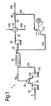
- Figure 1 shows a method of, and apparatus 1 for the, gasification of a liquid hydrocarbon stream 5.
- the liquid hydrocarbon stream 5 may comprise a hydrocarbon or mixture of hydrocarbons, such as a liquefied natural gas stream, or a synthetic hydrocarbon composition, such as that provided by the reaction of synthesis gas in a Fischer-Tropsch process.
- Liquefied natural gas can be provided by the treatment and liquefaction of natural gas in a manner known in the art.
- the liquid hydrocarbon stream 5 is provided at a feed pressure.
- liquid hydrocarbon such as liquefied natural gas
- the liquefied gas may be pressurised at temperatures below 0 °C or at a temperature of approximately -160 °C and at or near atmospheric pressure. This storage is discussed in more detail in relation to Figure 2a .
- the feed pressure of the liquid hydrocarbon stream 5 will be dependent upon the pressure to which the stream is pumped to transport it to the gasification apparatus 1.
- the feed pressure is less than 8 bar, and more preferably in the range of 1 to less than 8 bar.
- step (a) the liquid hydrocarbon stream 5 at the feed pressure is passed to a liquid hydrocarbon stream pump 10, where it is pressurised to provide a pressurised liquid hydrocarbon stream 15 at a pressure higher than the feed pressure.
- the liquid hydrocarbon stream pump 10 is preferably an electrical pump. It is intended to raise the pressure of the liquid hydrocarbon stream 5 to the pressure at which the subsequent heat exchange step is to be carried out - the "cold recovery pressure".
- the cold recovery pressure is preferably in the range of 8 to less than 50 bar, more preferably in the range of 8 to less than 40 bar, even more preferably in the range of 8 to less than 30 bar.
- the pressurised liquid hydrocarbon stream 15 is then passed to a hydrocarbon stream heat exchanger 30 in step (b), where it is warmed against one or more vapour recycle streams 115, to provide a warmed liquid hydrocarbon stream 35 and one or more liquefied recycle streams 125.
- a hydrocarbon stream heat exchanger 30 in step (b), where it is warmed against one or more vapour recycle streams 115, to provide a warmed liquid hydrocarbon stream 35 and one or more liquefied recycle streams 125.
- vapour recycle streams 115 In the embodiment shown in Figure 1 , only a single vapour recycle stream 115 and liquefied recycle stream 125 are shown, although two, three or four or more of each stream may be present. Where there are two or more vapour recycle streams 115, these streams are advantageously provided at different pressures. This embodiment is discussed in greater detail in relation to the embodiment of Figure 3 .
- the hydrocarbon stream heat exchanger 30 may be selected from a shell and tube, a plate and fin and a printed circuit heat exchanger. It is important that the temperature of the pressurised liquid hydrocarbon stream 15 at the cold recovery pressure is not raised above the bubble point (i.e. the temperature at which the pressurised liquid hydrocarbon stream 15 first produces bubbles of vapour) of the composition during the heat exchange, in order to ensure that the stream remains liquid, more preferably fully liquid. This is because it is more difficult and less efficient to compress a multiphase vapour/liquid stream than a single phase liquid stream.
- the warmed liquid hydrocarbon stream 35 exits the hydrocarbon stream heat exchanger 30 and one or more portions are passed to a warmed hydrocarbon stream pump 40.
- the warmed hydrocarbon stream pump 40 is preferably an electrical pump. It is preferred that all of the warmed liquid hydrocarbon stream 35 is passed to the warmed hydrocarbon stream pump 40.
- the warmed hydrocarbon stream pump 40 pressurises the one or more portions of the warmed liquid hydrocarbon stream 35 to provide one or more pressurised warmed liquid hydrocarbon streams 45, at least one of which is at a minimum pipeline pressure or higher.
- a single pressurised warmed liquid hydrocarbon stream 45 is shown in Figure 1 , which will be at or above the minimum pipeline pressure.
- the portion or portions of the pressurised warmed liquid hydrocarbon stream(s) 45 at the minimum pipeline pressure or higher can be gasified and passed to a gas consumer.
- minimum pipeline pressure is the required pipeline pressure of the consumer of the vaporised hydrocarbon, such as a gas network.
- This pressurisation step ensures that the portion or portions of the pressurised warmed liquid hydrocarbon stream 45 intended to provide the network gas is/are at a pressure equal to or higher than that of the pipeline pressure of the gas network. It is significantly more energy efficient to pressurise a liquid stream to the pipeline pressure or above, than a corresponding evaporated gaseous stream.
- One or more of the one or more pressurised warmed liquid hydrocarbon streams 45 can be passed to one or more hydrocarbon stream heaters 50.
- the hydrocarbon stream heaters 50 are supplied with one or more heat sources 345 to vaporise the pressurised warmed liquid hydrocarbon.
- the one or more heat sources 345 preferably have a temperature of less than or equal to ambient temperature, such as an ambient air or ambient water sources, such as a seawater stream.
- the hydrocarbon stream heaters 50 produce one or more gaseous hydrocarbon streams 55, at least one of which will be at the minimum pipeline pressure or higher, and a cooled heat source 355, such as a cooled air or cooled water, such as seawater, stream.
- the hydrocarbon stream heater 50 is an open rack vaporiser (ORV).
- the upper pressure limit to which the warmed liquid hydrocarbon stream(s) 35 can be pumped is determined by the maximum operating pressure of the hydrocarbon stream heater 50.
- open rack vaporisers have a maximum operating pressure of 140 to 150 bar. It is preferred that the pressure of the pressurised warmed liquid hydrocarbon stream(s) 45 which is at a minimum pipeline pressure or higher is between the minimum pipeline pressure and 140 bar.
- the warmed liquid hydrocarbon stream 35 is pressurised to provide the pressurised warmed liquid hydrocarbon stream 45 as a supercritical hydrocarbon stream. Under supercritical conditions, the pressurised warmed liquid hydrocarbon stream 45 loses its latent heat capacity such that it can be more easily heated.
- a gaseous hydrocarbon stream splitting device 60 can split at least one of the one or more gaseous hydrocarbon streams 55 into two or more parts 55a, 55b.
- Figure 1 shows the splitting of a single gaseous hydrocarbon stream 55, which is at or above the minimum pipeline pressure, into two parts, a first part 55a and a second part 55b.
- the second part, 55b can be passed to consumers of the gaseous hydrocarbon. If this is provided above the minimum pipeline pressure, then the pressure of the stream may be reduced by an appropriate expansion device.
- the embodiment of Figure 2a provides an example of such pressure reduction using a turbine to generate additional power.
- the first part, 55a is passed to a recycle turbine 110, where it is dynamically expanded to provide one or more expanded gaseous hydrocarbon streams 115.
- a single expanded gaseous hydrocarbon stream 115 is shown in Figure 1 .
- the recycle turbine 110 converts the useful work released by the dynamic expansion of the first part, 55a of the gaseous hydrocarbon stream 55 into kinetic energy to turn the shaft 112 of an electric generator 120.
- the electric generator can provide electrical power to meet the needs of the gasification facility.
- two or more gaseous hydrocarbon streams 55 can be provided by the one or more hydrocarbon stream heaters 50.
- a first gaseous hydrocarbon stream which is at or above the pipeline pressure, can be passed to a gas network, while a second gaseous hydrocarbon stream can be passed to the recycle turbine for dynamic expansion.
- the one or more expanded gaseous hydrocarbon streams 115 produced by the recycle turbine 110 can be provided at one or more expansion pressures.
- the one or more expansion pressures should be less than the suction pressure of the one or more gaseous hydrocarbon streams 55 passed to the turbine.
- the power which can be generated from the recycle turbine 110 is dependent, amongst various factors, upon the pressure ratio of the turbine i.e. the ratio of the pressure of the expanded gaseous hydrocarbon stream 115 to the pressure of the part 55a of the one or more gaseous hydrocarbon streams sent to the recycle turbine 110.
- Gas expansion is more efficient at pressures less than the supercritical range, such that suction pressures in the range of 60 to 80 bar are preferred.
- the one or more expanded gaseous hydrocarbon streams 115 are passed to the hydrocarbon stream heat exchanger 30 as at least a part of the one or more vapour recycle streams.
- the one or more vapour recycle streams 115 are provided entirely from the one or more expanded gaseous hydrocarbon streams 115, such that the vapour recycle stream and expanded gaseous hydrocarbon stream are one and the same.
- the one or more vapour recycle streams 115 are liquefied in the hydrocarbon stream heat exchanger 30 against the pressurised liquid hydrocarbon stream 15 to provide a liquefied recycle stream 125.
- Figure 1 shows the liquefaction of a single vapour recycle stream 115 to a single liquefied recycle stream 125.
- the liquefied recycle stream 125 produced by the hydrocarbon stream heat exchanger 30 is at the feed pressure of the liquid hydrocarbon stream 5, then it can be passed directly to the liquid hydrocarbon stream 5. Such an embodiment is discussed in relation to Figure 2a below.
- the pressures of the one or more liquefied recycle streams 125 are above the feed pressure of the liquid recycle stream 5, then they can passed to the suction of one or more recycle stream pumps 130.
- the one or more recycle stream pumps 130 are preferably electrical pumps.
- the one or more recycle pumps 130 pressurise the one or more liquefied recycle streams 125 to provide one or more pressurised liquefied recycle streams 135 at the cold recovery pressure.
- the one or more liquefied recycle streams 125 are preferably fully liquefied streams, because the recycle stream pump 130 can operate most efficiently with a single phase liquid stream. Rather than using multiple recycle stream pumps 130 when there is more than one liquefied recycle stream 125, a multi-stage recycle stream pump 130 may be more economical. In the embodiment shown in Figure 1 , a single liquefied recycle stream 125 is passed to a single recycle stream pump 130.
- the one or more pressurised liquefied recycle streams 135 can then be combined with the pressurised liquid hydrocarbon stream 15, via one or more hydrocarbon stream mixing devices 20, to provide pressurised liquid hydrocarbon stream 15a, which is a combined stream, and is passed to the hydrocarbon stream heat exchanger 30.
- the part 55a of the of the one or more gaseous hydrocarbon streams 55 which is passed to the recycle turbine 110 should be maximised.
- the one or more expanded gaseous hydrocarbon streams 115 produced by the recycle turbine 110 must be subsequently liquefied so that they may be recycled.
- the portion of the one or more gaseous hydrocarbon streams 55 which can be recycled depends upon the cooling duty available in the hydrocarbon stream heat exchanger 30 from the pressurised liquid hydrocarbon stream 15 and the energy required to cool and liquefy the vapour recycle stream 115 in the hydrocarbon stream heat exchanger 30.
- the cooling duty of the pressurised liquid hydrocarbon stream 15 is dependent upon the temperature change of the stream i.e. the extent to which it is warmed in the hydrocarbon stream heat exchanger 30, as well as the specific heat capacity of the stream.
- the specific heat capacity increases with decreasing stream pressure.
- the cooling capacity of the liquefied natural gas stream will also increase.
- the cooling capacity of liquefied natural gas at 10 bar is approximately 1.75% more than the cooling capacity at 75 bar. This provides a significant effect in terms of the cooling duty of this stream. Thus lower cold recovery pressures are preferred for this reason.
- the temperature change of the pressurised liquid hydrocarbon stream 15 in the heat exchanger will depend upon the temperature of the warmed liquid hydrocarbon stream 35. This temperature is related to the working pressure of the heat exchanger 30.
- the higher the pressure the lower the specific heat capacity of the pressurised liquid hydrocarbon stream 15, and thus the lower the cooling capacity. Consequently, the choice of cold recovery pressure is a balance between the specific heat capacity of the liquid hydrocarbon and the temperature increase of the liquid hydrocarbon in the heat exchanger 30.
- a further limitation on the cooling duty provided by the pressurised liquefied hydrocarbon stream 15 is that this stream should remain in the liquid phase in order to allow it to be efficiently pressurised in the warmed hydrocarbon stream pump 40.
- the energy required to cool and liquefy the vapour recycle stream 115 is a function of the specific heat capacity of the vapour recycle stream, the reduction in temperature of the stream in the hydrocarbon stream heat exchanger 30, the enthalpy of liquefaction of the vapour recycle stream at the discharge pressure of the recycle turbine 110, and the energy of any subcooling.
- the extent to which the one or more gaseous hydrocarbon streams 55 can be expanded through the recycle turbine 110 and reliquefied in the hydrocarbon stream heat exchanger 30 depends upon the degree of expansion which is carried out in the recycle turbine 110. The greater the expansion, the lower the pressure of the vapour recycle stream 115 passed to the hydrocarbon stream heat exchanger 30. The lower the pressure of the vapour recycle stream 115, the lower the temperature at which it will liquefy in the hydrocarbon stream heat exchanger 30.
- the capacity of the pressurised liquid hydrocarbon stream 15 to liquefy the vapour recycle stream 115 mainly depends upon the pressure difference.
- a ratio of the cold recovery pressure to the pressure of the vapour recycle stream 115 in the range of 2 to 3 is advantageous because it provides a neat cooling curve for the vapour recycle stream 115.
- the split ratio i.e. the extent to which the liquid hydrocarbon can be recycled after vaporisation
- the split ratio can be approximately 27% i.e. 27% by weight of the one or more gaseous hydrocarbon streams 55 can be passed to the recycle turbine 110 for energy production and then reliquefied in the hydrocarbon stream heat exchanger 30 and returned upstream of the heat exchanger. In this case, approximately one third of the flow can be expanded.
- the method disclosed herein may not have a single optimum point.
- Optimisation will depend upon the composition of the liquid hydrocarbon stream, its temperature, as well as other factors such as the temperature approach inside the hydrocarbon stream heat exchanger between the pressurised liquid hydrocarbon stream and the vapour recycle stream.
- a regasification plant with a 5 million metric ton pre annum (MTPA) design i.e. the production of second part 55b of the one or more gaseous hydrocarbon streams 55
- MTPA metric ton pre annum
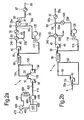
- the liquid hydrocarbon stream 5 is provided from a storage tank 400, by pumping a liquid hydrocarbon feed stream 405 with a feed pump 410, such as a submerged pump.
- the feed pump 410 is preferably an electrical pump.
- the feed pump 410 provides a pumped liquid hydrocarbon stream 415, which can be passed through a feed valve 420, to provide the liquid hydrocarbon stream 5 at feed pressure.
- the liquid hydrocarbon is normally stored in tank 400 under cryogenic conditions.
- the liquid hydrocarbon when it is liquefied natural gas, it can be stored at temperatures of less than -150 °C in a thermally insulated tank.
- the liquid hydrocarbon can be at or near atmospheric pressure, such as approximately 1 bar.
- hydrocarbon gas vapour also called boil off gas.
- hydrocarbon gas vapour can be withdrawn from at or near the top of storage tank 400 as a boil off gas stream 455, and passed to the suction side of a boil off gas compressor 460.
- the boil off gas compressor 460 can be mechanically driven by a boil off gas compressor driver 470, such as an electric driver powered by electricity generated by the recycle stream electric generator 120.
- the boil off gas compressor 460 compresses the boil off gas stream 455 to provide a compressed boil off gas stream 465.
- the heat of compression can then be removed from the compressed boil off gas stream 465, and this condensed in a boil off gas condenser 480.
- the boil off gas condenser 480 provides a liquefied boil off gas stream 485, which can be returned to the storage tank 400.
- the compressed boil off gas stream 465 may be condensed against a liquefied hydrocarbon stream (not shown), for instance a liquefied hydrocarbon stream drawn from the tank 400.
- an optional further heater 70 is provided to warm the gaseous hydrocarbon stream 55 against a heat source to provide (warmed) gaseous hydrocarbon stream 55c prior to passing it to the gaseous hydrocarbon stream splitting device 60.
- the heat source preferably has a temperature of less than or equal to ambient temperature, such as an ambient air or ambient water sources, such as a seawater stream or a hydrocarbon stream produced in the gasification process.
- the optional further heater 70 is advantageous if the gaseous hydrocarbon stream 55 is produced at too low a temperature for a portion, 55e, to be passed to gas consumers. For instance if the gaseous hydrocarbon stream 55 is provided at or below 0 °C, additional warming could be required to prevent condensation of water vapour on associated pipework.
- a gaseous hydrocarbon stream splitting device 60 provides a first part 55d of the (warmed) gaseous hydrocarbon stream 55c for dynamic expansion and power generation in recycle turbine 110.
- FIG. 2a shows a further optional aspect of the method and apparatus in which the second part 55e of the (warmed) gaseous hydrocarbon stream 55c is passed to the suction of a pipeline turbine 80.
- the pipeline turbine 80 dynamically expands the second part 55e of the (warmed) gaseous hydrocarbon stream 55c to provide an expanded gaseous hydrocarbon stream 85.
- the useful work extracted from the second part 55e of stream 55c is used to mechanically drive a pipeline electric generator 82 via shaft 81 to produce electrical power.
- the expanded gaseous hydrocarbon stream 85 may be passed to a further heater 87, in which it can be heated to, for example, 10-15 °C in order to redress any cooling resulting from the expansion in the hydrocarbon stream turbine 80.
- the further heater 87 provides a gaseous hydrocarbon pipeline stream 95 which can be passed to hydrocarbon gas consumers.
- the further heater 87 may be provided with a heat source, such as an ambient heat source, having a temperature of less than or equal to ambient temperature.
- the heat source may be one or more of an ambient air source, an ambient water source such as a seawater stream, and a hydrocarbon stream produced in the gasification process
- the optional hydrocarbon stream turbine 80 is advantageous when the warmed liquid hydrocarbon stream 35 is pumped to a pressure above the pipeline pressure by warmed hydrocarbon stream pump 40.
- the second part 55e of the (warmed) gaseous hydrocarbon stream 55c would be provided at a pressure above the pipeline pressure, and thus require pressure reduction before it can be passed to the gas network.
- the pressure reduction of the second part 55e of stream 55c can thus be used to generate additional power.
- the warmed liquid hydrocarbon stream 35 may be pumped to a pressure above the pipeline pressure in order to provide a particular suction pressure for the recycle turbine 110, which is fed by the first part 55c of the (warmed) gaseous hydrocarbon stream 55c.
- Figure 2b provides alternative embodiments of the method and apparatus 1 disclosed herein in which optional further heaters 90, 140 are provided to warm the first and second parts 55a, 55b of the gaseous hydrocarbon stream 55.
- Optional further heaters 90, 140 are preferably supplied with heat sources having a temperature of less than or equal to ambient temperature.
- the first part 55a of gaseous hydrocarbon stream 55 can be warmed by further heater 140 which preferably has a heat source having a temperature of less than or equal to ambient temperature, to provide a (warmed) first part 55f of the gaseous hydrocarbon stream 55 to the recycle turbine 110.
- This can be advantageous in controlling the suction temperature of the stream to be expanded in the recycle turbine 110 in order to maintain efficient operation.
- the second part 55b of the gaseous hydrocarbon stream 55 can be warmed in optional further heater 90 to provide gaseous hydrocarbon pipeline stream 95a.
- the optional further heater 90 is advantageous if the second part 55b of gaseous hydrocarbon stream 55 is too cold to be passed to the gas network, and must be warmed prior to distribution.
- the liquefied recycle stream 125 produced by liquefying the vapour recycle stream 115 against the pressurised liquid hydrocarbon stream 15, is passed directly to liquid hydrocarbon stream 5 via hydrocarbon stream mixing device 20a to provide a (combined) liquid hydrocarbon stream 5a.
- This line-up may be used when the recycle turbine 110 provides an expanded gaseous hydrocarbon stream (vapour recycle stream) 115 at the feed pressure of the liquid hydrocarbon stream 5.
- liquid hydrocarbon stream pump 10 would have to be increased to handle (combined) liquefied hydrocarbon stream 5a, comprising both the liquefied hydrocarbon stream 5 and the liquefied recycle stream 125, CAPEX savings are provided because no recycle stream pump is required.
- Figure 2c provides an alternative embodiment of the method and apparatus 1 disclosed herein in which all, rather than a part, of a gaseous hydrocarbon stream 55 is passed to the recycle turbine 110a for power generation.
- the recycle turbine 110 may be a multi-stage turbine.
- Such a multi-stage recycle turbine 110a can provide two discharge streams, a first expanded gaseous hydrocarbon stream 115a, and a second expanded gaseous hydrocarbon stream 115b.
- the first expanded recycle stream 115a can be an intermediate pressure stream which can be used to provide the gaseous hydrocarbon for export. In order to avoid subsequent repressurisation of the first expanded recycle stream 115a, it should be provided at a pressure at or above, preferably at, the pipeline pressure.
- the second expanded gaseous hydrocarbon stream 115b can be an intermediate pressure stream which can be used as a vapour recycle stream.
- the first expanded gaseous hydrocarbon stream 115a can be passed to a further heater 87b, in which it can be heated to, for example 10-15 °C, in order to raise the gas to a temperature suitable for export.
- the further heater 87b may be provided with a heat source having a temperature of less than or equal to ambient temperature.
- the further heater 87b provides a gaseous hydrocarbon pipeline stream 95b which can be passed to hydrocarbon gas consumers.
- first expanded gaseous hydrocarbon stream 115a is at a pressure above the pipeline pressure, it can be further expanded in a hydrocarbon stream turbine (not shown) in order to generate additional power and reduce the pressure of this stream to the pipeline pressure for export.
- This embodiment is less preferred because two turbines are thus required.
- a single turbine which would be a multi-stage recycle turbine 110a, which would provide the first expanded gaseous hydrocarbon stream 115a at pipeline pressure, as well as the second expanded gaseous hydrocarbon stream 115b which is to be used as the vapour recycle stream.
- the use of a single turbine in the line-up shown in Figure 2c provides CAPEX savings.
- the second expanded gaseous hydrocarbon stream 115b can be passed to hydrocarbon stream heat exchanger 30 for liquefaction against the liquid hydrocarbon stream 15 as described for the embodiment of Figure 1 .
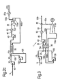
- FIG 3 shows a further embodiment of the method and apparatus 1 disclosed herein in which multiple vapour recycle streams 115, operating at different pressures, are liquefied in the hydrocarbon stream heat exchanger 30.
- the provision of two or more vapour recycle streams 115 at different pressures is advantageous because it allows improved thermal transfer in the heat exchanger 30.
- the cooling curves of multiple vapour recycle streams 115 can be used to provide a better match to the heating curve of the (combined) pressurised liquid hydrocarbon stream 15a.
- the liquid hydrocarbon stream 5 can be a liquefied natural gas stream, provided at a feed pressure of, for example, 1 bar, and pressurised to a cold recovery pressure of, for example, 30 bar by liquid natural gas stream pump 10.
- the pressurised LNG stream 15 is then combined with a liquefied recycle stream 125 at a mixing temperature of, for example, -146 °C by natural gas stream mixing device 20 to provide the (combined) pressurised LNG stream 15a with a mass flow of, for example, 50 kg/s.
- the (combined) pressurised LNG stream 15a is passed to the natural gas stream heat exchanger 30, which can be a condenser.
- the condenser 30 heats the (combined) pressurised LNG stream 15a to provide a warmed LNG stream 35 at a temperature of, for example, -95 °C.
- the warmed LNG stream 35 is passed to warmed LNG stream pump 40, where it is pressurised to a pressure of, for example, 75 bar to provide pressurised warmed LNG stream 45.
- the pressurised warmed LNG stream 45 can be vaporised in an LNG stream heater 50 with a heat source, for example to a temperature in the range of 10-15 °C to provide a gaseous natural gas stream 55.
- the heat source preferably has a temperature of less than or equal to ambient temperature, and is more preferably an ambient heat source.
- the LNG stream heater 50 is preferably an open rack vaporiser.
- the gaseous natural gas stream 55 can have a mass flow of, for example, 50 kg/s, and is passed to a gaseous natural gas stream splitting device 60.
- the gaseous natural gas stream 55 is split into two parts.
- a first part, 55a is passed to a recycle turbine 110, for example at a mass flow of 19 kg/s.
- a second part 55b, can be passed to a gas network.
- the second stream will be at the pipeline pressure of 75 bar, if the pressurised warmed LNG stream 45 is pumped to this pressure.
- the first part 55a of the gaseous natural gas stream 55 is dynamically expanded in the recycle turbine 110 from the pipeline pressure, for example 75 bar.
- the recycle turbine 110b can be a multi-stage recycle turbine.
- Such a multi-stage recycle turbine 110b can provide two discharge streams, a first expanded gaseous natural gas stream 115c, for example with a pressure of 25 bar and a mass flow of 7 kg/s, and a second expanded gaseous natural gas stream 115d, for example with a pressure of 10 bar and a mass flow of 12 kg/s.
- Both first and second expanded gaseous natural gas streams 115a, 115b can then be passed to condenser 30 for liquefaction against the liquid LNG stream 15.
- the first expanded gaseous natural gas stream 115c can be liquefied in condenser 30, for example at -115 °C, to provide a first liquefied recycle stream 125c.
- the second expanded gaseous natural gas stream 115d can be liquefied in condenser 30, for example at -130 °C, to provide a second liquefied recycle stream 125d.
- the first expanded gaseous natural gas stream 115c will be more easily liquefied in the condenser 30 than the second stream 115d, because the former stream is at a higher pressure.
- the first expanded stream 115c will therefore have better heat exchanger temperature heat transfer, and avoid too low a minimum internal temperature approach to the exchanger 30.
- the first and second liquefied recycle streams 125c, 125d can then be passed to a multi-stage recycle stream pump 130 where they are pressurised, for example to 31 bar, to provide a pressurised liquefied recycle stream 135, for example with a mass flow of 19 kg/s.
- the pressurised liquefied recycle stream 135 can then be mixed with the pressurised LNG stream 15 via natural gas stream mixing device 20.
- the pressurised LNG stream 15 is provided by LNG stream 5, which can be drawn from an LNG source such as a storage tank.
- LNG stream 5 When the LNG stream 5 has a mass flow of 31 kg/s, the pressurised LNG stream 15 will have a similar mass flow.
- pressurised LNG stream 15a comprising the pressurised LNG stream 15 and pressurised liquefied recycle stream 135, will have the required mass flow of 50 kg/s. Consequently, this embodiment provides a line-up in which 38 (i.e. 19/50 kg/s) % by mass of the natural gas is recycled to the condenser 30.
- the multi-stage recycle turbine 110 can produce 2.5 MW/MTPA power when used with the exemplary mass flows, pressures and temperatures provided in this embodiment.
- the power consumption of pumps 10, 40 and 130 is 0,4 MW/MTPA in total, such that a net power production of 2.1 MW/MTPA is provided. This is above the power threshold necessary to provide an autonomous gasification terminal and thus would not require any external power, or utilise any fuel to generate additional power, during steady state operation.
- one or both of the multi-stage recycle turbine 110 and the multi-stage recycle stream pump 130 can be replaced by two or more recycle turbines 110b and two or more recycle stream pumps respectively.
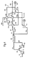
- Figure 4 provides a further embodiment of the method and apparatus 1 disclosed herein.
- a Rankine cycle is incorporated into the regasification process according to the embodiment of Figure 1 to increase the generated power. It will be apparent that such a Rankine cycle can be used with any embodiment disclosed herein.
- One or more Rankine circuits 200 can be added to generate additional power from the pressurised warmed liquid hydrocarbon stream 45.
- the pressurised warmed liquid hydrocarbon stream 45 is provided by warmed hydrocarbon stream pump 40, in which it has been pressurised to the minimum pipeline pressure or higher.
- the pressurised warmed liquid hydrocarbon stream is pressurised to supercritical pressure, for example in the range of 65 to 85 bars.
- the pressurised warmed liquid hydrocarbon stream 45 Prior to vaporisation in the one or more LNG stream heaters 50, the pressurised warmed liquid hydrocarbon stream 45 can be passed to a working fluid heat exchanger 210, where it is warmed against an expanded vaporised working fluid stream 245 in the Rankine circuit 200, to provide a pressurised (further) warmed liquid hydrocarbon stream 45a and a liquefied working fluid stream 215.
- the working fluid preferably has a condensing temperature between -20 and -50 °C.
- a refrigerant is useful as the working fluid.
- Preferred working fluids are selected from one or more of the group comprising: tetrafluoromethane (R14), ethane, pentafluoroethane (R125) and propane.
- the cold energy from the pressurised warmed liquid hydrocarbon stream 45 is used to liquefy the working fluid in the expanded vaporised working fluid stream 245.
- the liquefied working fluid stream 215 thus produced can then be passed to a working fluid pump 220, in which it is pressurised to provide a pressurised liquefied working fluid stream 225.
- the liquefied working fluid stream 215 is pumped to a pressure in the range of 5 to 12 bar, more preferably about 6.2 bars. It is generally preferred to pump the liquefied working fluid stream 215 to its dew point pressure at ambient temperature.
- Such a liquefied working fluid stream can then be vapourised against a heat source at 15 °C.
- the pressurised liquefied working fluid stream 225 can then be passed to a working fluid heater 230, where it is vaporised against a heat source.
- the heat source preferably has a temperature of less than or equal to ambient temperature, such as an ambient air or ambient water feed stream 325.
- the heat source may be a hydrocarbon stream generated as part of the gasification method.
- the working fluid heater 230 is preferably an open rack vaporiser.
- the working fluid heater 230 provides a vaporised working fluid stream 235, and a cooled heat source, such as a water, air or hydrocarbon stream 345a, which is a cooled stream.
- the vaporised working fluid stream 235 can then passed to a working fluid turbine 240, where it is dynamically expanded to provide power and the expanded vaporised working fluid stream 245.
- the power is produced by mechanically driving a working fluid electric generator 250 with the working fluid turbine 240 via shaft 242.
- the vaporised working fluid stream 235 is expanded to a pressure in the range of 1 to 3 bar, more preferably about 1.2 bars.
- expansion to a minimum pressure in the working fluid turbine would be preferred in order to maximise power generation.
- the pressurised (further) warmed liquid hydrocarbon stream 45a can then be vaporised against a heat source 345a to provide a cooled heat source, such as a cooled air or water stream 355a, and a gaseous hydrocarbon stream 55.
- the heat source 345a preferably has a temperature of less than or equal to ambient temperature, and may be the air, water or hydrocarbon stream 345a produced by the working fluid heater 230.
- Such an embodiment is capable of producing 4 MW/MTPA power.
- Approximately 2 MW/MTPA can be generated from the recycle turbine 110 and recycle stream electric generator 120, in a similar manner to the embodiment of Figure 1 .
- a further 2 MW/MTPA can be generated from the working fluid turbine 240 and working fluid electric generator 250.
- 4 MW/MTPA power generation is equivalent to the emission of 12200 ton/year of carbon dioxide produced by electricity generation from the combustion of natural gas in a combined cycle power generation apparatus. This elimination of carbon dioxide emissions represents a significant advantage, with the further benefit that the additional electricity generated which is not used in the steady state operation of the gasification facility can be exported to other facilities or an external electricity grid.
Landscapes
- Engineering & Computer Science (AREA)
- Mechanical Engineering (AREA)
- General Engineering & Computer Science (AREA)
- Filling Or Discharging Of Gas Storage Vessels (AREA)
- Separation By Low-Temperature Treatments (AREA)
Claims (16)
- Verfahren zur Vergasung eines flüssigen Kohlenwasserstoffstroms (5), um einen gasförmigen Kohlenwasserstoffstrom (55) und Energie bereitzustellen, umfassend wenigstens die Schritte:(a) Unter-Druck-Setzen eines flüssigen Kohlenwasserstoffstroms (5), welcher mit einem Zufuhrdruck vorliegt, um einen unter Druck gesetzten flüssigen Kohlenwasserstoffstrom (15) mit einem Druck zur Kaltgewinnung bereitzustellen;(b) Wärmeaustauschen des unter Druck gesetzten flüssigen Kohlenwasserstoffstroms (15) gegen einen oder mehrere Dampfrezyklierungsströme (115), um einen erwärmten flüssigen Kohlenwasserstoffstrom (35) und einen oder mehrere verflüssigte Rezyklierungsströme (125) bereitzustellen;(c) Leiten des einen oder der mehreren verflüssigten Rezyklierungsströme (125), erforderlichenfalls nach einem Unter-Druck-Setzen, zu dem verflüssigten Kohlenwasserstoffstrom (5) oder dem unter Druck gesetzten flüssigen Kohlenwasserstoffstrom (15) oder zu beiden;(d) Unter-Druck-Setzen von einem oder mehreren Teilen des erwärmten flüssigen Kohlenwasserstoffstroms (35), um einen oder mehrere unter Druck gesetzte erwärmte flüssige Kohlenwasserstoffströme (45) bereitzustellen, wobei wenigstens einer bei einem Mindestpipelinedruck oder darüber vorliegt;(e) Verdampfen von einem oder mehreren der unter Druck gesetzten flüssigen Kohlenwasserstoffströme (45), wobei wenigstens einer bei einem Mindestpipelinedruck oder darüber vorliegt, mit einer oder mehreren Wärmequellen (345), um einen oder mehrere gasförmige Kohlenwasserstoffströme (55) bereitzustellen, wobei wenigstens einer bei dem Mindestpipelinedruck oder darüber vorliegt;(f) dynamisches Expandieren von wenigstens einem Teil (55, 55a, 55e) von wenigstens einem des einen oder der mehreren gasförmigen Kohlenwasserstoffströme (55), um Energie und einen oder mehrere expandierte gasförmige Kohlenwasserstoffströme (115) bereitzustellen, wobei wenigstens ein Teil des einen oder der mehreren expandierten gasförmigen Kohlenwasserstoffströme wenigstens einen Teil des einen oder der mehreren Dampfrezyklierungsströme (115) bildet.
- Verfahren nach Anspruch 1, wobei alle Wärmeaustausch- und Verdampfungsschritte, welche zu einem Anstieg in der Temperatur von jedwedem der Kohlenwasserstoffströme (15, 45, 55) führen, mit einer Wärmequelle mit einer Temperatur von weniger als oder im Wesentlichen gleich der Umgebungstemperatur oder einem Kohlenwasserstoffstrom (115), welcher im Vergasungsverfahren gebildet wird, oder beiden durchgeführt werden.
- Verfahren nach Anspruch 1 oder Anspruch 2, wobei zwischen den Schritten (e) und (f) ein gasförmiger Kohlenwasserstoffstrom (55) in einen ersten Teil (55a, 55d) des gasförmigen Kohlenwasserstoffstroms (55) und in einen zweiten Teil (55b, 55e) des gasförmigen Kohlenwasserstoffstroms (55) aufgetrennt wird, und wobei im Schritt (f) der erste Teil (55a, 55d) des gasförmigen Kohlenwasserstoffstroms (55) dynamisch expandiert wird, um einen oder mehrere erste expandierte gasförmige Kohlenwasserstoffströme als den einen oder die mehreren Dampfrezyklierungsströme (115) bereitzustellen.
- Verfahren nach Anspruch 3, wobei im Schritt (f) die dynamische Expansion wenigstens zwei erste expandierte gasförmige Kohlenwasserstoffströme als wenigstens zwei Dampfrezyklierungsströme (115) bereitstellt, wobei jeder dieser Ströme bei einem unterschiedlichen Druck vorliegt, im Schritt (b) der Wärmeaustausch zwei erste verflüssigte Kohlenwasserstoffströme (125) liefert, und im Schritt des Unter-Druck-Setzens (c) die wenigstens zwei ersten verflüssigten Rezyklierungsströme (125) unter Druck gesetzt werden, um einen unter Druck gesetzten verflüssigten Rezyklierungsstrom (135) bereitzustellen, welcher zum unter Druck gesetzten flüssigen Kohlenwasserstoffstrom (15) geleitet wird.
- Verfahren nach Anspruch 4, wobei die dynamische Expansion im Schritt (f) in einer Mehrstufenrezyklierungsturbine (110) ausgeführt wird und im Schritt (c) das Unter-Druck-Setzen in einer mehrstufigen Pumpe für Rezyklierungsströme (130) ausgeführt wird.
- Verfahren nach einem der vorstehenden Ansprüche, ferner umfassend den Schritt des Erhitzens des gasförmigen Kohlenwasserstoffstroms (55) mit einer Wärmequelle (70) zwischen den Schritten (e) und (f).
- Verfahren nach einem der Ansprüche 3 bis 5, ferner umfassend die Schritte:- Erhitzen des ersten Teils (55a) des gasförmigen Kohlenwasserstoffstroms (55) mit einer Wärmequelle vor der dynamischen Expansion im Schritt (f); und- Erhitzen des zweiten Teils (55b) des gasförmigen Kohlenwasserstoffstroms (55) mit einer Wärmequelle.
- Verfahren nach einem der vorstehenden Ansprüche, wobei der Schritt in (c) eines oder beides umfasst:(i) Leiten von wenigstens einem des einen oder der mehreren verflüssigten Rezyklierungsströme (125) zum flüssigen Kohlenwasserstoffstrom (5), wenn der eine oder die mehreren verflüssigten Rezyklierungsströme (125) mit einem Zufuhrdruck vorliegen, oder(ii) Unter-Druck-Setzen von wenigstens einem des einen oder der mehreren verflüssigten Rezyklierungsströme (125), um einen unter Druck gesetzten verflüssigten Rezyklierungsstrom (135) bereitzustellen, welcher bei einem Druck zur Kaltgewinnung vorliegt, und Leiten des unter Druck gesetzten verflüssigten Rezyklierungsstroms zum unter Druck gesetzten flüssigen Kohlenwasserstoffstrom (15), wenn der Druck des einen oder der mehreren verflüssigten Rezyklierungsströme (125) über dem Zufuhrdruck liegt.
- Verfahren nach einem der vorstehenden Ansprüche, wobei wenigstens einer (55c) des einen oder der mehreren gasförmigen Kohlenwasserstoffströme (55) bei einem höheren Druck als dem Mindestpipelinedruck vorliegt, wobei das Verfahren ferner die Schritte umfasst:(g) dynamisches Expandieren von wenigstens einem Teil (55e) des wenigstens einen gasförmigen Kohlenwasserstoffstroms (55c), welcher bei einem höheren Druck als dem Mindestpipelinedruck vorliegt, in einer Pipelineturbine (80), welche Pipelineturbine mechanisch einen Pipelinegenerator (82) antreibt, um Elektrizität und einen expandierten gasförmigen Kohlenwasserstoffstrom (85) bereitzustellen, welcher bei einem Druck von wenigstens dem Mindestpipelinedruck vorliegt; und(h) Erhitzen des expandierten gasförmigen Kohlenwasserstoffstroms (85) mit einer Wärmequelle, um einen erhitzten gasförmigen Kohlenwasserstoffstrom (95) bereitzustellen; und(i) Leiten des erhitzten gasförmigen Kohlenwasserstoffstroms (95) zu einem Gasnetzwerk.
- Verfahren nach einem der vorstehenden Ansprüche, ferner umfassend zwischen den Schritten (d) und (e) die Schritte:- Wärmeaustauschen von wenigstens einem des einen oder der mehreren unter Druck gesetzten erwärmten flüssigen Kohlenwasserstoffströme (45) gegen einen expandierten verdampften Arbeitsfluidstrom (245), um einen verflüssigten Arbeitsfluidstrom (215) bereitzustellen;- Unter-Druck-Setzen des verflüssigten Arbeitsfluidstroms (215), um einen unter Druck gesetzten verflüssigten Arbeitsfluidstrom (225) bereitzustellen;- Verdampfen des unter Druck gesetzten verflüssigten Arbeitsfluidstroms (225) mit einer Wärmequelle (325), um einen verdampften Arbeitsfluidstrom (235) bereitzustellen; und- dynamisches Expandieren des verdampften Arbeitsfluidstroms (235) in einer Arbeitsfluidturbine (240), welche Arbeitsfluidturbine (240) mechanisch einen Arbeitsfluidgenerator (250) antreibt, um Elektrizität und den expandierten verdampften Arbeitsfluidstrom (245) bereitzustellen.
- Verfahren nach einem der vorstehenden Ansprüche, wobei der Druck zur Kaltgewinnung im Bereich von 10 bis weniger als 60 bar, stärker bevorzugt von 20 bis weniger als 50 bar liegt und/oder der Mindestpipelinedruck größer als oder gleich 60 bar, stärker bevorzugt größer als oder gleich 70 bar, noch stärker bevorzugt größer als oder gleich 75 bar ist.
- Verfahren nach einem der vorstehenden Ansprüche, wobei die eine oder die mehreren Wärmequellen (345) eine Temperatur von weniger als oder gleich Umgebungstemperatur besitzen.
- Verfahren nach einem der vorstehenden Ansprüche, wobei der flüssige Kohlenwasserstoffstrom (5) verflüssigtes Erdgas ist und der eine oder die mehreren gasförmigen Kohlenwasserstoffströme (55) einen Erdgasstrom (55b) umfassen.
- Vorrichtung (1) zur Vergasung eines flüssigen Kohlenwasserstoffstroms (5), um einen gasförmigen Kohlenwasserstoffstrom (55) bereitzustellen, welche Vorrichtung wenigstens umfasst:- eine Pumpe (10) für einen flüssigen Kohlenwasserstoffstrom, um einen flüssigen Kohlenwasserstoffstrom (5), welcher mit einem Zufuhrdruck vorliegt, unter Druck zu setzen, um einen unter Druck gesetzten verflüssigten Kohlenwasserstoffstrom (15) mit einem Druck zur Kaltgewinnung bereitzustellen;- einen Wärmeaustauscher (30) für einen Kohlenwasserstoffstrom, um den unter Druck gesetzten flüssigen Kohlenwasserstoffstrom (15) gegen einen oder mehrere Dampfrezyklierungsströme (115) einem Wärmeaustausch zu unterziehen, um einen erwärmten flüssigen Kohlenwasserstoffstrom (35) und einen oder mehrere verflüssigte Rezyklierungsströme (125) bereitzustellen;- eine Pumpe (40) für einen erwärmten Kohlenwasserstoffstrom, um einen oder mehrere Teile des erwärmten flüssigen Kohlenwasserstoffstroms (35) unter Druck zu setzten, um einen oder mehrere unter Druck gesetzte erwärmte flüssige Kohlenwasserstoffströme (45) bereitzustellen, wovon wenigstens einer bei einem Mindestpipelinedruck oder darüber vorliegt;- eine Wärmequelle (345), um einen oder mehrere der unter Druck gesetzten erwärmten flüssigen Kohlenwasserstoffströme (45) zu verdampfen, wobei wenigstens einer bei dem Mindestpipelinedruck oder darüber vorliegt, um einen oder mehrere gasförmige Kohlenwasserstoffströme bereitzustellen;- eine Rezyklierungsturbine (110), um wenigstens einen Teil (55, 55a, 55e) von wenigstens einem des einen oder der mehreren gasförmigen Kohlenwasserstoffströme (55) dynamisch zu expandieren, um eine Welle (115) anzutreiben und einen oder mehrere expandierte gasförmige Kohlenwasserstoffströme bereitzustellen, wovon wenigstens ein Teil wenigstens einen Teil des einen oder der mehreren Dampfrezyklierungsströme (115) bildet; und- ein oder mehrere Mischvorrichtungen (20) für Kohlenwasserstoffstrom, um den einen oder die mehreren verflüssigten Rezyklierungsströme (125) oder einen daraus abgeleiteten Strom (135) in den verflüssigten Kohlenwasserstoffstrom (5) oder den unter Druck gesetzten verflüssigten Kohlenwasserstoffstrom (15) einzubringen.
- Vorrichtung (1) nach Anspruch 14, ferner umfassend:- eine Pumpe (130) für einen Rezyklierungsstrom, um den einen oder die mehreren verflüssigten Rezyklierungsströme (125) unter Druck zu setzen, um einen unter Druck gesetzten verflüssigten Rezyklierungsstrom (135), welcher mit einem Druck zur Kaltgewinnung vorliegt, bereitzustellen; undwobei die Mischvorrichtung (20) für Kohlenwasserstoffstrom den unter Druck gesetzten verflüssigten Kohlenwasserstoffstrom (135) in den unter Druck gesetzten flüssigen Kohlenwasserstoffstrom (15) einbringt.
- Vorrichtung (1) nach Anspruch 14 oder Anspruch 15, wobei die Wärmequelle (345) eine Temperatur von weniger als oder im Wesentlichen gleich der Umgebungstemperatur besitzt.
Priority Applications (2)
| Application Number | Priority Date | Filing Date | Title |
|---|---|---|---|
| EP10730803.3A EP2454518B1 (de) | 2009-07-16 | 2010-07-14 | Verfahren zur vergasung eines flüssigen kohlenwasserstoffstroms und gerät dafür |
| CY20131100668T CY1114487T1 (el) | 2009-07-16 | 2013-08-07 | Μεθοδος για την αεριοποιηση ρευματος υγρων υδρογονανθρακων και αντιστοιχη διαταξη |
Applications Claiming Priority (3)
| Application Number | Priority Date | Filing Date | Title |
|---|---|---|---|
| EP09165671 | 2009-07-16 | ||
| EP10730803.3A EP2454518B1 (de) | 2009-07-16 | 2010-07-14 | Verfahren zur vergasung eines flüssigen kohlenwasserstoffstroms und gerät dafür |
| PCT/EP2010/060117 WO2011006917A1 (en) | 2009-07-16 | 2010-07-14 | Method for the gasification of a liquid hydrocarbon stream and an apparatus therefor |
Publications (2)
| Publication Number | Publication Date |
|---|---|
| EP2454518A1 EP2454518A1 (de) | 2012-05-23 |
| EP2454518B1 true EP2454518B1 (de) | 2013-05-08 |
Family
ID=41402395
Family Applications (1)
| Application Number | Title | Priority Date | Filing Date |
|---|---|---|---|
| EP10730803.3A Not-in-force EP2454518B1 (de) | 2009-07-16 | 2010-07-14 | Verfahren zur vergasung eines flüssigen kohlenwasserstoffstroms und gerät dafür |
Country Status (4)
| Country | Link |
|---|---|
| EP (1) | EP2454518B1 (de) |
| CY (1) | CY1114487T1 (de) |
| ES (1) | ES2414029T3 (de) |
| WO (1) | WO2011006917A1 (de) |
Families Citing this family (3)
| Publication number | Priority date | Publication date | Assignee | Title |
|---|---|---|---|---|
| DE102013200572A1 (de) * | 2013-01-16 | 2014-07-17 | Siemens Aktiengesellschaft | Vorrichtung zur Regasifizierung von Flüssigerdgas und zugehöriges Verfahren |
| EP3184876A1 (de) | 2015-12-23 | 2017-06-28 | Shell Internationale Research Maatschappij B.V. | Regasifizierungsterminal zur flüssigerdgaskogeneration |
| CN114060842A (zh) * | 2021-12-13 | 2022-02-18 | 欧科能源技术(天津)有限公司 | 电加热直热式液态烃气化装置 |
Family Cites Families (6)
| Publication number | Priority date | Publication date | Assignee | Title |
|---|---|---|---|---|
| FR1348190A (fr) * | 1962-04-24 | 1964-01-04 | Conch Int Methane Ltd | Procédé de gazéification d'un gaz liquéfié avec production simultanée d'énergie mécanique |
| AT294787B (de) * | 1968-07-29 | 1971-12-10 | Linde Ag | Verfahren zum Verdampfen und Anwärmen flüssigen Erdgases |
| DE2604304A1 (de) * | 1976-02-04 | 1977-08-11 | Linde Ag | Verfahren zur energierueckgewinnung aus verfluessigten gasen |
| DE2633713C2 (de) * | 1976-07-27 | 1983-10-20 | Linde Ag, 6200 Wiesbaden | Verfahren zur Erwärmung von verflüssigtem Erdgas |
| EP1904782A4 (de) | 2005-07-18 | 2015-01-14 | Fluor Tech Corp | Konfigurationen und verfahren zur energieerzeugung in lng-wiederverdampfungsendgeräten |
| JP5354543B2 (ja) * | 2007-02-01 | 2013-11-27 | フルオー・テクノロジーズ・コーポレイシヨン | 外気式気化器 |
-
2010
- 2010-07-14 EP EP10730803.3A patent/EP2454518B1/de not_active Not-in-force
- 2010-07-14 ES ES10730803T patent/ES2414029T3/es active Active
- 2010-07-14 WO PCT/EP2010/060117 patent/WO2011006917A1/en not_active Ceased
-
2013
- 2013-08-07 CY CY20131100668T patent/CY1114487T1/el unknown
Also Published As
| Publication number | Publication date |
|---|---|
| CY1114487T1 (el) | 2016-10-05 |
| ES2414029T3 (es) | 2013-07-17 |
| EP2454518A1 (de) | 2012-05-23 |
| WO2011006917A1 (en) | 2011-01-20 |
Similar Documents
| Publication | Publication Date | Title |
|---|---|---|
| JP5958730B2 (ja) | 冷熱発電システム、冷熱発電システムを備えるエネルギシステム、及び冷熱発電システムの利用方法、エネルギシステムの利用方法、及び冷熱発電システムのプレオーバーブースト圧力の設定方法 | |
| JP6538884B2 (ja) | ガス処理システムを含む船舶 | |
| KR102287843B1 (ko) | 가스 처리 시스템 | |
| US7493763B2 (en) | LNG-based power and regasification system | |
| JP5202945B2 (ja) | Lng再ガス化と統合された発電のための構造及び方法 | |
| JP5026588B2 (ja) | Lng再ガス化および発電 | |
| US7900451B2 (en) | Power and regasification system for LNG | |
| EP0059956B1 (de) | Zurückgewinnung von Energie durch die Verdampfung von Flüssigerdgas | |
| JPH04502196A (ja) | Lngからの動力発生 | |
| KR20150115126A (ko) | 액화가스 처리 시스템 | |
| US6116031A (en) | Producing power from liquefied natural gas | |
| EP2278210A1 (de) | Verfahren zur Verdampfung flüssigen Erdgases und Vorrichtung hierzu | |
| KR20220047785A (ko) | 가스 흐름의 액화 또는 발전을 통해 냉동 에너지를 회수하기 위한 방법 | |
| EP2454518B1 (de) | Verfahren zur vergasung eines flüssigen kohlenwasserstoffstroms und gerät dafür | |
| KR20150121321A (ko) | 액화가스 처리 시스템 | |
| JP2017075594A (ja) | 液化ガスによる超臨界圧冷熱発電システム | |
| KR101922273B1 (ko) | 액화가스 처리 시스템 | |
| KR102461330B1 (ko) | 액화가스 재기화 방법 | |
| KR20150115101A (ko) | 액화가스 처리 시스템 | |
| KR101922275B1 (ko) | 액화가스 처리 시스템 | |
| KR101922276B1 (ko) | 액화가스 처리 시스템 | |
| JP2019066063A (ja) | 天然ガスの製造装置および天然ガスの製造方法 | |
| KR20150115098A (ko) | 액화가스 처리 시스템 |
Legal Events
| Date | Code | Title | Description |
|---|---|---|---|
| PUAI | Public reference made under article 153(3) epc to a published international application that has entered the european phase |
Free format text: ORIGINAL CODE: 0009012 |
|
| 17P | Request for examination filed |
Effective date: 20120103 |
|
| AK | Designated contracting states |
Kind code of ref document: A1 Designated state(s): AL AT BE BG CH CY CZ DE DK EE ES FI FR GB GR HR HU IE IS IT LI LT LU LV MC MK MT NL NO PL PT RO SE SI SK SM TR |
|
| DAX | Request for extension of the european patent (deleted) | ||
| GRAP | Despatch of communication of intention to grant a patent |
Free format text: ORIGINAL CODE: EPIDOSNIGR1 |
|
| GRAS | Grant fee paid |
Free format text: ORIGINAL CODE: EPIDOSNIGR3 |
|
| GRAA | (expected) grant |
Free format text: ORIGINAL CODE: 0009210 |
|
| AK | Designated contracting states |
Kind code of ref document: B1 Designated state(s): AL AT BE BG CH CY CZ DE DK EE ES FI FR GB GR HR HU IE IS IT LI LT LU LV MC MK MT NL NO PL PT RO SE SI SK SM TR |
|
| REG | Reference to a national code |
Ref country code: GB Ref legal event code: FG4D |
|
| REG | Reference to a national code |
Ref country code: AT Ref legal event code: REF Ref document number: 611270 Country of ref document: AT Kind code of ref document: T Effective date: 20130515 Ref country code: CH Ref legal event code: EP |
|
| REG | Reference to a national code |
Ref country code: IE Ref legal event code: FG4D |
|
| REG | Reference to a national code |
Ref country code: DE Ref legal event code: R096 Ref document number: 602010006973 Country of ref document: DE Effective date: 20130704 |
|
| REG | Reference to a national code |
Ref country code: ES Ref legal event code: FG2A Ref document number: 2414029 Country of ref document: ES Kind code of ref document: T3 Effective date: 20130717 |
|
| REG | Reference to a national code |
Ref country code: GR Ref legal event code: EP Ref document number: 20130401544 Country of ref document: GR Effective date: 20130829 |
|
| REG | Reference to a national code |
Ref country code: AT Ref legal event code: MK05 Ref document number: 611270 Country of ref document: AT Kind code of ref document: T Effective date: 20130508 |
|
| REG | Reference to a national code |
Ref country code: LT Ref legal event code: MG4D |
|
| REG | Reference to a national code |
Ref country code: NL Ref legal event code: VDEP Effective date: 20130508 |
|
| PG25 | Lapsed in a contracting state [announced via postgrant information from national office to epo] |
Ref country code: FI Free format text: LAPSE BECAUSE OF FAILURE TO SUBMIT A TRANSLATION OF THE DESCRIPTION OR TO PAY THE FEE WITHIN THE PRESCRIBED TIME-LIMIT Effective date: 20130508 Ref country code: SI Free format text: LAPSE BECAUSE OF FAILURE TO SUBMIT A TRANSLATION OF THE DESCRIPTION OR TO PAY THE FEE WITHIN THE PRESCRIBED TIME-LIMIT Effective date: 20130508 Ref country code: PT Free format text: LAPSE BECAUSE OF FAILURE TO SUBMIT A TRANSLATION OF THE DESCRIPTION OR TO PAY THE FEE WITHIN THE PRESCRIBED TIME-LIMIT Effective date: 20130909 Ref country code: IS Free format text: LAPSE BECAUSE OF FAILURE TO SUBMIT A TRANSLATION OF THE DESCRIPTION OR TO PAY THE FEE WITHIN THE PRESCRIBED TIME-LIMIT Effective date: 20130908 Ref country code: SE Free format text: LAPSE BECAUSE OF FAILURE TO SUBMIT A TRANSLATION OF THE DESCRIPTION OR TO PAY THE FEE WITHIN THE PRESCRIBED TIME-LIMIT Effective date: 20130508 Ref country code: AT Free format text: LAPSE BECAUSE OF FAILURE TO SUBMIT A TRANSLATION OF THE DESCRIPTION OR TO PAY THE FEE WITHIN THE PRESCRIBED TIME-LIMIT Effective date: 20130508 Ref country code: NO Free format text: LAPSE BECAUSE OF FAILURE TO SUBMIT A TRANSLATION OF THE DESCRIPTION OR TO PAY THE FEE WITHIN THE PRESCRIBED TIME-LIMIT Effective date: 20130808 Ref country code: LT Free format text: LAPSE BECAUSE OF FAILURE TO SUBMIT A TRANSLATION OF THE DESCRIPTION OR TO PAY THE FEE WITHIN THE PRESCRIBED TIME-LIMIT Effective date: 20130508 |
|
| PG25 | Lapsed in a contracting state [announced via postgrant information from national office to epo] |
Ref country code: HR Free format text: LAPSE BECAUSE OF FAILURE TO SUBMIT A TRANSLATION OF THE DESCRIPTION OR TO PAY THE FEE WITHIN THE PRESCRIBED TIME-LIMIT Effective date: 20130508 Ref country code: BG Free format text: LAPSE BECAUSE OF FAILURE TO SUBMIT A TRANSLATION OF THE DESCRIPTION OR TO PAY THE FEE WITHIN THE PRESCRIBED TIME-LIMIT Effective date: 20130808 Ref country code: PL Free format text: LAPSE BECAUSE OF FAILURE TO SUBMIT A TRANSLATION OF THE DESCRIPTION OR TO PAY THE FEE WITHIN THE PRESCRIBED TIME-LIMIT Effective date: 20130508 |
|
| PG25 | Lapsed in a contracting state [announced via postgrant information from national office to epo] |
Ref country code: LV Free format text: LAPSE BECAUSE OF FAILURE TO SUBMIT A TRANSLATION OF THE DESCRIPTION OR TO PAY THE FEE WITHIN THE PRESCRIBED TIME-LIMIT Effective date: 20130508 |
|
| PG25 | Lapsed in a contracting state [announced via postgrant information from national office to epo] |
Ref country code: SK Free format text: LAPSE BECAUSE OF FAILURE TO SUBMIT A TRANSLATION OF THE DESCRIPTION OR TO PAY THE FEE WITHIN THE PRESCRIBED TIME-LIMIT Effective date: 20130508 Ref country code: DK Free format text: LAPSE BECAUSE OF FAILURE TO SUBMIT A TRANSLATION OF THE DESCRIPTION OR TO PAY THE FEE WITHIN THE PRESCRIBED TIME-LIMIT Effective date: 20130508 Ref country code: BE Free format text: LAPSE BECAUSE OF FAILURE TO SUBMIT A TRANSLATION OF THE DESCRIPTION OR TO PAY THE FEE WITHIN THE PRESCRIBED TIME-LIMIT Effective date: 20130508 Ref country code: CZ Free format text: LAPSE BECAUSE OF FAILURE TO SUBMIT A TRANSLATION OF THE DESCRIPTION OR TO PAY THE FEE WITHIN THE PRESCRIBED TIME-LIMIT Effective date: 20130508 Ref country code: EE Free format text: LAPSE BECAUSE OF FAILURE TO SUBMIT A TRANSLATION OF THE DESCRIPTION OR TO PAY THE FEE WITHIN THE PRESCRIBED TIME-LIMIT Effective date: 20130508 |
|
| PG25 | Lapsed in a contracting state [announced via postgrant information from national office to epo] |
Ref country code: NL Free format text: LAPSE BECAUSE OF FAILURE TO SUBMIT A TRANSLATION OF THE DESCRIPTION OR TO PAY THE FEE WITHIN THE PRESCRIBED TIME-LIMIT Effective date: 20130508 Ref country code: IT Free format text: LAPSE BECAUSE OF FAILURE TO SUBMIT A TRANSLATION OF THE DESCRIPTION OR TO PAY THE FEE WITHIN THE PRESCRIBED TIME-LIMIT Effective date: 20130508 Ref country code: RO Free format text: LAPSE BECAUSE OF FAILURE TO SUBMIT A TRANSLATION OF THE DESCRIPTION OR TO PAY THE FEE WITHIN THE PRESCRIBED TIME-LIMIT Effective date: 20130508 Ref country code: MC Free format text: LAPSE BECAUSE OF FAILURE TO SUBMIT A TRANSLATION OF THE DESCRIPTION OR TO PAY THE FEE WITHIN THE PRESCRIBED TIME-LIMIT Effective date: 20130508 |
|
| PLBE | No opposition filed within time limit |
Free format text: ORIGINAL CODE: 0009261 |
|
| STAA | Information on the status of an ep patent application or granted ep patent |
Free format text: STATUS: NO OPPOSITION FILED WITHIN TIME LIMIT |
|
| 26N | No opposition filed |
Effective date: 20140211 |
|
| REG | Reference to a national code |
Ref country code: IE Ref legal event code: MM4A |
|
| REG | Reference to a national code |
Ref country code: DE Ref legal event code: R119 Ref document number: 602010006973 Country of ref document: DE Effective date: 20140201 |
|
| PG25 | Lapsed in a contracting state [announced via postgrant information from national office to epo] |
Ref country code: DE Free format text: LAPSE BECAUSE OF NON-PAYMENT OF DUE FEES Effective date: 20140201 |
|
| PG25 | Lapsed in a contracting state [announced via postgrant information from national office to epo] |
Ref country code: IE Free format text: LAPSE BECAUSE OF NON-PAYMENT OF DUE FEES Effective date: 20130714 |
|
| REG | Reference to a national code |
Ref country code: CH Ref legal event code: PL |
|
| PG25 | Lapsed in a contracting state [announced via postgrant information from national office to epo] |
Ref country code: CH Free format text: LAPSE BECAUSE OF NON-PAYMENT OF DUE FEES Effective date: 20140731 Ref country code: LI Free format text: LAPSE BECAUSE OF NON-PAYMENT OF DUE FEES Effective date: 20140731 |
|
| PG25 | Lapsed in a contracting state [announced via postgrant information from national office to epo] |
Ref country code: SM Free format text: LAPSE BECAUSE OF FAILURE TO SUBMIT A TRANSLATION OF THE DESCRIPTION OR TO PAY THE FEE WITHIN THE PRESCRIBED TIME-LIMIT Effective date: 20130508 |
|
| PG25 | Lapsed in a contracting state [announced via postgrant information from national office to epo] |
Ref country code: TR Free format text: LAPSE BECAUSE OF FAILURE TO SUBMIT A TRANSLATION OF THE DESCRIPTION OR TO PAY THE FEE WITHIN THE PRESCRIBED TIME-LIMIT Effective date: 20130508 Ref country code: MT Free format text: LAPSE BECAUSE OF FAILURE TO SUBMIT A TRANSLATION OF THE DESCRIPTION OR TO PAY THE FEE WITHIN THE PRESCRIBED TIME-LIMIT Effective date: 20130508 |
|
| PG25 | Lapsed in a contracting state [announced via postgrant information from national office to epo] |
Ref country code: LU Free format text: LAPSE BECAUSE OF NON-PAYMENT OF DUE FEES Effective date: 20130714 Ref country code: HU Free format text: LAPSE BECAUSE OF FAILURE TO SUBMIT A TRANSLATION OF THE DESCRIPTION OR TO PAY THE FEE WITHIN THE PRESCRIBED TIME-LIMIT; INVALID AB INITIO Effective date: 20100714 Ref country code: MK Free format text: LAPSE BECAUSE OF FAILURE TO SUBMIT A TRANSLATION OF THE DESCRIPTION OR TO PAY THE FEE WITHIN THE PRESCRIBED TIME-LIMIT Effective date: 20130508 |
|
| REG | Reference to a national code |
Ref country code: FR Ref legal event code: PLFP Year of fee payment: 7 |
|
| REG | Reference to a national code |
Ref country code: FR Ref legal event code: PLFP Year of fee payment: 8 |
|
| REG | Reference to a national code |
Ref country code: FR Ref legal event code: PLFP Year of fee payment: 9 |
|
| PG25 | Lapsed in a contracting state [announced via postgrant information from national office to epo] |
Ref country code: AL Free format text: LAPSE BECAUSE OF FAILURE TO SUBMIT A TRANSLATION OF THE DESCRIPTION OR TO PAY THE FEE WITHIN THE PRESCRIBED TIME-LIMIT Effective date: 20130508 |
|
| PGFP | Annual fee paid to national office [announced via postgrant information from national office to epo] |
Ref country code: GR Payment date: 20200610 Year of fee payment: 11 Ref country code: FR Payment date: 20200611 Year of fee payment: 11 |
|
| PGFP | Annual fee paid to national office [announced via postgrant information from national office to epo] |
Ref country code: ES Payment date: 20200803 Year of fee payment: 11 Ref country code: GB Payment date: 20200701 Year of fee payment: 11 Ref country code: CY Payment date: 20200611 Year of fee payment: 11 |
|
| GBPC | Gb: european patent ceased through non-payment of renewal fee |
Effective date: 20210714 |
|
| PG25 | Lapsed in a contracting state [announced via postgrant information from national office to epo] |
Ref country code: GB Free format text: LAPSE BECAUSE OF NON-PAYMENT OF DUE FEES Effective date: 20210714 |
|
| PG25 | Lapsed in a contracting state [announced via postgrant information from national office to epo] |
Ref country code: GR Free format text: LAPSE BECAUSE OF NON-PAYMENT OF DUE FEES Effective date: 20220207 Ref country code: FR Free format text: LAPSE BECAUSE OF NON-PAYMENT OF DUE FEES Effective date: 20210731 Ref country code: CY Free format text: LAPSE BECAUSE OF NON-PAYMENT OF DUE FEES Effective date: 20210714 |
|
| REG | Reference to a national code |
Ref country code: ES Ref legal event code: FD2A Effective date: 20220927 |
|
| PG25 | Lapsed in a contracting state [announced via postgrant information from national office to epo] |
Ref country code: ES Free format text: LAPSE BECAUSE OF NON-PAYMENT OF DUE FEES Effective date: 20210715 |