EP2451663B1 - Utility vehicle ventilation system - Google Patents
Utility vehicle ventilation system Download PDFInfo
- Publication number
- EP2451663B1 EP2451663B1 EP10752387.0A EP10752387A EP2451663B1 EP 2451663 B1 EP2451663 B1 EP 2451663B1 EP 10752387 A EP10752387 A EP 10752387A EP 2451663 B1 EP2451663 B1 EP 2451663B1
- Authority
- EP
- European Patent Office
- Prior art keywords
- filter
- air
- utility vehicle
- vehicle according
- channel
- Prior art date
- Legal status (The legal status is an assumption and is not a legal conclusion. Google has not performed a legal analysis and makes no representation as to the accuracy of the status listed.)
- Not-in-force
Links
Images


Classifications
-
- B—PERFORMING OPERATIONS; TRANSPORTING
- B60—VEHICLES IN GENERAL
- B60H—ARRANGEMENTS OF HEATING, COOLING, VENTILATING OR OTHER AIR-TREATING DEVICES SPECIALLY ADAPTED FOR PASSENGER OR GOODS SPACES OF VEHICLES
- B60H3/00—Other air-treating devices
- B60H3/06—Filtering
- B60H3/0608—Filter arrangements in the air stream
- B60H3/0633—Filter arrangements in the air stream with provisions for regenerating or cleaning the filter element
-
- B—PERFORMING OPERATIONS; TRANSPORTING
- B60—VEHICLES IN GENERAL
- B60H—ARRANGEMENTS OF HEATING, COOLING, VENTILATING OR OTHER AIR-TREATING DEVICES SPECIALLY ADAPTED FOR PASSENGER OR GOODS SPACES OF VEHICLES
- B60H1/00—Heating, cooling or ventilating devices
- B60H1/00357—Air-conditioning arrangements specially adapted for particular vehicles
- B60H1/00378—Air-conditioning arrangements specially adapted for particular vehicles for tractor or load vehicle cabins
-
- B—PERFORMING OPERATIONS; TRANSPORTING
- B60—VEHICLES IN GENERAL
- B60H—ARRANGEMENTS OF HEATING, COOLING, VENTILATING OR OTHER AIR-TREATING DEVICES SPECIALLY ADAPTED FOR PASSENGER OR GOODS SPACES OF VEHICLES
- B60H3/00—Other air-treating devices
- B60H3/06—Filtering
- B60H3/0608—Filter arrangements in the air stream
- B60H3/0641—Filter arrangements in the air stream near ventilating openings in the vehicle exterior
Definitions
- the invention relates to ventilation systems fitted to the cabs of utility vehicles, such as tractors, combine harvesters and plant machinery, said system serving to receive air from the environment, filter the air and supply the filtered air into the cab.
- Utility vehicles are often required to work in dusty environments.
- the cab in which the driver sits is typically fitted with a ventilation system which ensures the comfort and safe working environment for the driver.
- the filter, or filters, of the ventilation system often require routine cleaning or replacement. The period between filter servicing is significantly reduced when working in extremely dusty environments. In some cases, the filter requires attention several times a day leading to unacceptable downtime.
- the filter is often housed in such a way which requires the removal of several components to gain access thereto.
- FR-2,501,340 discloses an example utility vehicle comprising a ventilation system having a pre-filter upstream of a main filter.
- a utility vehicle comprising a ventilation system which receives air from the environment, filters the air and supplies the filtered air into a cab, the system comprising a fan to drive air through a channel from the environment to the cab, a main air filter arranged within a roof section of the cab and downstream of a pre-filter which rotates about a rotation axis which is substantially parallel to the air flow through the pre-filter.
- the rotation of the pre-filter reduces the particulate build up thereon due to the radial air flow created and the centrifugal forces exerted on the incident dust. Furthermore, the majority of the dust is removed from the air flow before reaching the main filter. Therefore, removal of the main filter is seldom required.
- the pre-filter can be located externally of the roof structure. This is particularly advantageous on a utility vehicle because maintenance (e.g. clearing) of the pre-filter does not require the time-consuming removal of components associated with the main cab structure.
- the pre-filter is mounted to an electric motor and, preferably, the electric motor is dedicated to rotating the pre-filter.
- the pre-filter is driven by a hydraulic motor or air-driven turbine.
- the channel immediately downstream of the pre-filter has a diameter which is less than the diameter of the pre-filter.
- the particulate removal effect is significantly improved.
- the dust thrown off of the periphery of the pre-filter is not reintroduced into the clean air flow. Instead, the removed dust is thrown against a wall of the channel and/or thrown out of a pre-filter module away from the intake air flow.
- the fan is preferably located downstream of the pre-filter and, preferably further still, downstream of the main filter. Therefore, the air is sucked through at least one of the pre-filter and main filter before being propelled into the cab.
- the fan is preferably driven by a dedicated electric motor.
- the system may further comprise an air conditioning evaporator to cool the air. This may be disposed in the air stream between the main filter and fan for example.
- the roof section of the cab is at least partly formed of moulded plastic and at least a portion of the channel is defined by channel elements moulded into the roof section.
- this reduces the number of components required to provide the ducting which channels the air between the various system elements.
- the channel preferably includes a recycle inlet through which recycled air from the cab is drawn, the recycle inlet being closable by a blocking element which is moveable between a normal position and a recycle position wherein the channel upstream of the recycle inlet is blocked to prevent the intake of air from the environment.
- a blocking element which is moveable between a normal position and a recycle position wherein the channel upstream of the recycle inlet is blocked to prevent the intake of air from the environment.
- this provides the option to block the intake of air from the surroundings. For example, this may be preferred when spraying chemicals on a crop field.
- the recycle inlet is preferably located upstream of the main filter and downstream of the pre-filter filter. This ensures continued filtering of the recycled air whilst allowing easy access to and/or removal of the pre-filter.
- the rotation axis is substantially vertical.
- this encourages the particulate matter collected by the pre-filter to fall under gravity away therefrom, thereby increasing the period between maintenance.
- the pre-filter and motor is preferably housed within a pre-filter housing which includes a covering inlet vent upstream of the pre-filter.
- the covering inlet vent may be removable to enable easy access to the pre-filter for cleaning and replacement.
- a portion of the channel between the main filter and pre-filter may be integrated within the roof section. This may leave only the pre-filter housing to be attached to the roof thus minimising components whilst enabling easy access to maintain the pre-filter.
- the pre-filter and motor may be integrated into a detachable pre-filter module which is mounted to the roof section.
- this allows an existing utility vehicle, with a conventional ventilation system, to be simply modified with the attachment of the pre-filter module. This minimises expense in that no modifications are necessary to the hardware of existing vehicles.
- the pre-filter module can be offered to the customers of vehicle manufacturers as an optional extra. In this case, the module can be added to the vehicle late in the assembly process, thus minimising any changes to the existing assembly line.
- the pre-filter module may include a channel portion downstream of the pre-filter having an outlet orifice which cooperates with an inlet vent formed in a face of the roof section. This enables simple attachment of the module to the roof section.
- a releasable wired link may be provided to releasably connect the motor to a power source located on the vehicle. Therefore, installation of the module simply involves the attachment of the module to the vehicle and then connection of the wired link to provide power to the motor.
- a tractor 10 comprises a pair of front steerable wheels 12 mounted on respective ends of a front axle 13, and a pair of rear wheels 14 which are at least partially covered by rear wheel fenders 15.
- a driver sits in a driver's seat 16, the space around which is protected by cab 18.
- a roll-over protection structure provides a framework for the cab 18 and includes a pair of front A-pillars 20, a pair of intermediate B-pillars 21, and a pair of rear C-pillars 22.
- the ROPS further includes a front generally transverse member 26, a rear generally transverse member 27 and a pair of generally longitudinal members 28 the combination of which provides a rigid support frame for the roof 24,25 and ventilation system to be described below.
- the tractor roof section includes a top moulded portion 25 and a bottom moulded portion 24 which are formed, for example, by blow-moulding plastic and cover the components of the ventilation system. It should be understood that the top roof section 25 is not shown in Figures 3 , 4 , 5 and 7 .
- the ventilation system Starting at the inlet of air, the ventilation system, referenced generally at 30, comprises a pre-filter 32 which is housed within a pre-filter unit 33.
- pre-filter unit 33 The construction and operation of pre-filter unit 33 will be described in more detail below.
- the pre-filter unit 33 is mounted to a first ducting section 34 which conveys the air-stream from pre-filter unit 33 to a main filter unit 35, the latter housing a main filter (not shown) through which the ventilation air-stream passes.
- the first ducting section 34 sealably connects to the main filter housing 35 by a generally rectangular attachment interface 36 which includes securing means (not shown) to hold the first ducting member 34 in position.
- this connection may be a simple male/female connection with the male part being associated with the first ducting section.
- the main filter contained within main filter unit 35 is formed of a fibrous material and serves to trap dust and particulate matter, thereby cleaning the air which has been drawn in from the environment via the pre-filter unit 33.
- a cover 38 is pivotally connected by hinges 39 to the top roof section 25.
- the cover 38 hinges upwardly and provides simple access to the pre-filter unit 33 for maintenance thereof. Furthermore, the main filter housing can be simply accessed by removal of first ducting section 34. To conceal the pre-filter unit 33 and first ducting section 34, the cover 38 conforms with the profile of the roof 24.
- a cover 40 encloses the pre-filter 32 and pivots downwardly to give access thereto.
- the air leaves the main filter unit 35 through outlet 42 ( Figure 4 ) and passes into a junction chamber 44.
- a flap 45 is movable between a normal position and a recycle position. In the recycle position (shown in Figures 3 and 4 ) the incoming air from outlet 42 is blocked and recycled air is allowed to pass from the cab interior via a cycle inlet 46 on to the H-vac unit 50. In the normal position the flap 45 serves to partially block the air from the recycle unit 46 and allow the filtered air from the main filter housing 35 to pass into a heating, ventilation and air conditioning (HVAC) unit 50. Typically, the normal position allows a mixture of 50% fresh air and 50% recycled air to pass into the HVAC unit 50.
- HVAC heating, ventilation and air conditioning
- the air-stream is conveyed from the junction housing 44 to the HVAC unit 50 by a second ducting section which is formed from side-walls 52 which are integrated into the overall roof structure.
- HVAC unit 50 is of a known type and includes a heater element to heat the air-stream when required, and an evaporator 54 which serves to cool the air-stream when required.
- the HVAC unit 50 is integrated into the bottom roof member 24, is secured to the rear transverse cab member 27 and is enclosed within the roof space formed between top roof member at 25 and the bottom roof member 24.
- the HVAC unit 50 serves as a heat exchanger through which the filtered air can be either heated or cooled as required.
- a pair of blowers 54 are arranged on the downstream side of the HVAC unit 50 and provide the propulsive force which draws in air from the environment and forces it out into the driver's cab 18.
- a dividing wall 55 splits the air-stream into a left-hand and right-hand sub-stream each having a respective blower 54.
- Each sub-stream of air is delivered into the cab 18 by third and fourth ducting sections 56, 57 having integrated air vents 58.
- the air-flow speed can be adjusted by the driver by appropriate control of the blower speed. Furthermore, the driver can tailor the clean air distribution by appropriate adjustment of the individual vents 58. The temperature of the air can be adjusted by appropriate control of the HVAC unit 50.
- the above-described arrangement includes a pre-filter unit 33 and first ducting member 34 which is integrated inside the profile of the roof 24 so as to conceal the presence thereof. These components can be added during assembly of the vehicle or at a later stage. However, it is envisaged that a pre-filter unit can be added as part of an additional module to a utility vehicle having a main filter only.
- FIGS 11 - 14 illustrate a second embodiment of the invention wherein a pre-filter module 60 is secured to an air intake of an existing utility vehicle ventilation system.
- a male flange 62 provides an extension of a first ducting section 64 and inserts into the intake vent (not shown) of a tractor's ventilation system which is located on the underside (overhang) of a cab roof externally of the driver's space.
- Locking screws 65 are provided to secure the pre-filter module 60 to the tractor.
- a pre-filter element 72 is housed within a pre-filter unit 73 which is connected to the first ducting member 64 so as to allow filtered air to pass from the pre-filter unit 73 into the tractor's ventilation system.
- the pre-filter element 72 is mounted on a shaft 74 which is connected to an electrical motor (not shown) which is housed within motor housing 75.
- the pre-filter element 72 is secured in fixed engagement with shaft 74 by locking nuts 76.
- a centring rod 77 is secured to the underside of flange 78 and serves as a guide for the shaft 74 to ensure that the latter maintains a central position.
- Flange 78 is annular in shape and includes an air intake orifice 80 which has a diameter less than that of the pre-filter element 72.
- pre-filter element 72 is held in close engagement with the flange 78 and the outside edge of pre-filter 72 overlaps the edge of inlet orifice 80 by a distance X.
- the pre-filter element 72 is rotated at a speed of approximately 1500-3000 rpm by the electrical motor.
- Air is drawn in through the rotating pre-filter element 72 and passes into a conical transfer housing 82 before being conveyed at 90° into first ducting section 64.
- the rotational motion of pre-filter element 72 creates a proximate radial airflow which forces particulate matter radially outwardly so as not to collect on the surface of pre-filter element 72. Due to the overlap X between the pre-filter element 72 and intake orifice 82 there is minimal airflow through the peripheral region of the former.
- the blocked particulate matter eventually falls downwardly due to gravity when it reaches the edge of pre-filter element 72.
- the substantially vertical orientation of the pre-filter exploits gravity to remove the blocked particulate matter.
- the overlap X prevents the ingress of particulate matter around the outside of pre-filter element 72, by effectively producing a labyrinth seal. Also, a subsidiary radial airflow exists between the pre-filter element 72 and the flange 78 which also blocks the particulate matter.
- pre-filter element 72 is enclosed by a perforated cover (not shown) for safety reasons.
- first ducting member 64 requires appropriate design in order to maintain a vertical rotation axis for the pre-filter element whilst enabling simple addition of the module to an existing system.
- the arrangement shown in Figures 12 - 14 is suitable for a tractor having an inlet vent which receives a vertical airflow.
- a pre-filter module may be designed to cater for an air intake which is horizontal in nature and is comparable to the pre-filter unit 33 and first ducting member 34 of the embodiment shown in Figures 2 - 10 .
- the motor housed within motor housing 75 is connected to a power supply by a detachable lead (not shown).
- a detachable lead (not shown).
- the integrated version shown in Figures 2 - 10 may include a hard wiring which does not require routine detachment.
- the male/female connection of the attachment interface 36 may include an integrated electrical connection to supply power from the vehicle to the pre-filter unit.
- the invention can be integrated into a new ventilation system for a tractor cab or, alternatively, achieved by providing an additional unit to an existing ventilation system.
- the pre-filter module 60 may be readily attached and detached to suit the operating conditions on a daily basis. For example, this allows a farmer to attach the pre-filter module when working in a dusty environment and detach the pre-filter module when not required so as to reduce the profile of the overall tractor.
- inventive ventilation system can be applied to other utility vehicles such as plant machinery and combine harvesters without deviating from the scope of the invention.
- the rotating pre-filter element described above in relation to the appended drawings is driven by an electric motor.
- the pre-filter element may be rotated by other means including a hydraulic motor or even an integrated turbine which is driven by the airflow through the ventilation system.
- a fan is disposed on the same shaft as the rotating pre-filter wherein the electric motor drives both elements.
- this provides additional propulsion to the air stream through the ventilation system.
- a utility vehicle comprising a ventilation system which receives air from the environment, filters the air and supplies the filtered air into a cab.
- the system comprises a fan to drive air through a channel from the environment to the cab, and a main air filter arranged within a roof section of the cab and downstream of a pre-filter.
- the pre-filter rotates about a rotation axis which is substantially parallel to the air flow through the pre-filter so as to reduce the particulate matter which reaches the main filter.
- the rotation of the pre-filter creates a centrifugal force and tangential airflow which forces the particulate matter radially outwardly to reduce the build-up of matter on the filter, thus reducing the frequency of servicing.
- the pre-filter can be integrated into a cab ventilation system or provided in a module which can be added to a vehicle having a conventional ventilation system.
Landscapes
- Engineering & Computer Science (AREA)
- Mechanical Engineering (AREA)
- Physics & Mathematics (AREA)
- Thermal Sciences (AREA)
- Air-Conditioning For Vehicles (AREA)
Description
- The invention relates to ventilation systems fitted to the cabs of utility vehicles, such as tractors, combine harvesters and plant machinery, said system serving to receive air from the environment, filter the air and supply the filtered air into the cab.
- Utility vehicles are often required to work in dusty environments. The cab in which the driver sits is typically fitted with a ventilation system which ensures the comfort and safe working environment for the driver. The filter, or filters, of the ventilation system often require routine cleaning or replacement. The period between filter servicing is significantly reduced when working in extremely dusty environments. In some cases, the filter requires attention several times a day leading to unacceptable downtime.
- To compound the problem of frequent filter maintenance, the filter is often housed in such a way which requires the removal of several components to gain access thereto.
-
FR-2,501,340 - It is an object of the invention to provide a utility vehicle ventilation system which requires less maintenance and, therefore, less downtime.
- It is another object of the invention to provide a utility vehicle ventilation system which is simple to maintain.
- It is yet another object of the invention to provide a utility vehicle ventilation system which requires less maintenance and which can be easily obtained from simple modification to existing utility vehicle ventilation systems.
- According to the invention there is provided a utility vehicle comprising a ventilation system which receives air from the environment, filters the air and supplies the filtered air into a cab, the system comprising a fan to drive air through a channel from the environment to the cab, a main air filter arranged within a roof section of the cab and downstream of a pre-filter which rotates about a rotation axis which is substantially parallel to the air flow through the pre-filter. By providing a rotating pre-filter upstream of the main filter, maintenance of the system is required less often.
- The rotation of the pre-filter reduces the particulate build up thereon due to the radial air flow created and the centrifugal forces exerted on the incident dust. Furthermore, the majority of the dust is removed from the air flow before reaching the main filter. Therefore, removal of the main filter is seldom required.
- The pre-filter can be located externally of the roof structure. This is particularly advantageous on a utility vehicle because maintenance (e.g. clearing) of the pre-filter does not require the time-consuming removal of components associated with the main cab structure.
- Preferably, the pre-filter is mounted to an electric motor and, preferably, the electric motor is dedicated to rotating the pre-filter. Alternatively, the pre-filter is driven by a hydraulic motor or air-driven turbine.
- Preferably, the channel immediately downstream of the pre-filter has a diameter which is less than the diameter of the pre-filter. Advantageously, by overlapping beyond the area of the channel with the pre-filter, the particulate removal effect is significantly improved. The dust thrown off of the periphery of the pre-filter is not reintroduced into the clean air flow. Instead, the removed dust is thrown against a wall of the channel and/or thrown out of a pre-filter module away from the intake air flow.
- The fan is preferably located downstream of the pre-filter and, preferably further still, downstream of the main filter. Therefore, the air is sucked through at least one of the pre-filter and main filter before being propelled into the cab. The fan is preferably driven by a dedicated electric motor.
- The system may further comprise an air conditioning evaporator to cool the air. This may be disposed in the air stream between the main filter and fan for example.
- Preferably, the roof section of the cab is at least partly formed of moulded plastic and at least a portion of the channel is defined by channel elements moulded into the roof section. Advantageously, this reduces the number of components required to provide the ducting which channels the air between the various system elements.
- The channel preferably includes a recycle inlet through which recycled air from the cab is drawn, the recycle inlet being closable by a blocking element which is moveable between a normal position and a recycle position wherein the channel upstream of the recycle inlet is blocked to prevent the intake of air from the environment. Advantageously, this provides the option to block the intake of air from the surroundings. For example, this may be preferred when spraying chemicals on a crop field. The recycle inlet is preferably located upstream of the main filter and downstream of the pre-filter filter. This ensures continued filtering of the recycled air whilst allowing easy access to and/or removal of the pre-filter.
- Preferably, the rotation axis is substantially vertical. Advantageously, this encourages the particulate matter collected by the pre-filter to fall under gravity away therefrom, thereby increasing the period between maintenance.
- The pre-filter and motor is preferably housed within a pre-filter housing which includes a covering inlet vent upstream of the pre-filter. The covering inlet vent may be removable to enable easy access to the pre-filter for cleaning and replacement.
- A portion of the channel between the main filter and pre-filter may be integrated within the roof section. This may leave only the pre-filter housing to be attached to the roof thus minimising components whilst enabling easy access to maintain the pre-filter.
- Alternatively, the pre-filter and motor may be integrated into a detachable pre-filter module which is mounted to the roof section. Advantageously, this allows an existing utility vehicle, with a conventional ventilation system, to be simply modified with the attachment of the pre-filter module. This minimises expense in that no modifications are necessary to the hardware of existing vehicles. Furthermore, the pre-filter module can be offered to the customers of vehicle manufacturers as an optional extra. In this case, the module can be added to the vehicle late in the assembly process, thus minimising any changes to the existing assembly line.
- The pre-filter module may include a channel portion downstream of the pre-filter having an outlet orifice which cooperates with an inlet vent formed in a face of the roof section. This enables simple attachment of the module to the roof section.
- A releasable wired link may be provided to releasably connect the motor to a power source located on the vehicle. Therefore, installation of the module simply involves the attachment of the module to the vehicle and then connection of the wired link to provide power to the motor.
- Further advantages of the invention will become apparent from the following description of specific embodiments with reference to the appended drawings in which:
-
Figure 1 is a perspective view of a tractor; -
Figure 2 is a perspective view showing the roof of a tractor in accordance with a first embodiment of the invention; -
Figure 3 is a perspective view of the cab of the tractor ofFigure 2 shown with part of the roof removed; -
Figure 4 is a perspective view showing in isolation the ventilation system of the tractor of -
Figure 2 . -
Figure 5 is a perspective view of the ventilation system ofFigure 4 viewed from the underside; -
Figure 6 is a perspective view of the top roof element of the utility vehicle cab ofFigure 2 ; -
Figure 7 is a perspective view of the ventilation system ofFigure 4 showing the lower part of the roof construction; -
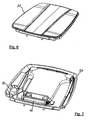
Figure 8 is a perspective view of the ventilation system ofFigure 4 showing the direction of airflow there-through. -
Figure 9 is a plan view of the ventilation system ofFigure 4 showing the direction of airflow there-through. -
Figure 10 is a rear view of part of the roof of the utility vehicle ofFigure 2 . -
Figure 11 is a perspective view of an add-on pre-filter module in accordance with a second embodiment of the invention; -
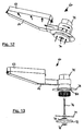
Figure 12 is a perspective view of the pre-filter module ofFigure 11 showing the direction of airflow there-through; -
Figure 13 is a perspective view of the pre-filter module ofFigure 11 showing components of the pre-filter in exploded form; -
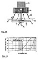
Figure 14 is a sectional view of a pre-filter in accordance with the second embodiment of the invention; and, -
Figure 15 is a plot illustrating the filtration efficiency of the ventilation system for both a rotating pre-filter and a stationary pre-filter. - With reference to
Figure 1 , atractor 10 comprises a pair of frontsteerable wheels 12 mounted on respective ends of afront axle 13, and a pair ofrear wheels 14 which are at least partially covered byrear wheel fenders 15. A driver sits in a driver'sseat 16, the space around which is protected bycab 18. A roll-over protection structure (ROPS) provides a framework for thecab 18 and includes a pair of front A-pillars 20, a pair of intermediate B-pillars 21, and a pair of rear C-pillars 22. The ROPS further includes a front generally transversemember 26, a rear generally transversemember 27 and a pair of generally longitudinal members 28 the combination of which provides a rigid support frame for theroof - With reference to
Figures 2 - 7 , a first embodiment of the invention is shown in which the tractor roof section includes a top mouldedportion 25 and a bottom mouldedportion 24 which are formed, for example, by blow-moulding plastic and cover the components of the ventilation system. It should be understood that thetop roof section 25 is not shown inFigures 3 ,4 ,5 and7 . - Starting at the inlet of air, the ventilation system, referenced generally at 30, comprises a pre-filter 32 which is housed within a
pre-filter unit 33. The construction and operation ofpre-filter unit 33 will be described in more detail below. - The
pre-filter unit 33 is mounted to afirst ducting section 34 which conveys the air-stream frompre-filter unit 33 to amain filter unit 35, the latter housing a main filter (not shown) through which the ventilation air-stream passes. Thefirst ducting section 34 sealably connects to themain filter housing 35 by a generallyrectangular attachment interface 36 which includes securing means (not shown) to hold thefirst ducting member 34 in position. For example, this connection may be a simple male/female connection with the male part being associated with the first ducting section. - The main filter contained within
main filter unit 35 is formed of a fibrous material and serves to trap dust and particulate matter, thereby cleaning the air which has been drawn in from the environment via thepre-filter unit 33. - With reference in particular to
Figure 2 , acover 38 is pivotally connected byhinges 39 to thetop roof section 25. Thecover 38 hinges upwardly and provides simple access to thepre-filter unit 33 for maintenance thereof. Furthermore, the main filter housing can be simply accessed by removal offirst ducting section 34. To conceal thepre-filter unit 33 andfirst ducting section 34, thecover 38 conforms with the profile of theroof 24. - With reference to
Figure 10 , acover 40 encloses the pre-filter 32 and pivots downwardly to give access thereto. - Working upstream, the air leaves the
main filter unit 35 through outlet 42 (Figure 4 ) and passes into a junction chamber 44. Aflap 45 is movable between a normal position and a recycle position. In the recycle position (shown inFigures 3 and4 ) the incoming air fromoutlet 42 is blocked and recycled air is allowed to pass from the cab interior via acycle inlet 46 on to the H-vac unit 50. In the normal position theflap 45 serves to partially block the air from therecycle unit 46 and allow the filtered air from themain filter housing 35 to pass into a heating, ventilation and air conditioning (HVAC)unit 50. Typically, the normal position allows a mixture of 50% fresh air and 50% recycled air to pass into theHVAC unit 50. - The air-stream is conveyed from the junction housing 44 to the
HVAC unit 50 by a second ducting section which is formed from side-walls 52 which are integrated into the overall roof structure. -
HVAC unit 50 is of a known type and includes a heater element to heat the air-stream when required, and anevaporator 54 which serves to cool the air-stream when required. TheHVAC unit 50 is integrated into thebottom roof member 24, is secured to the reartransverse cab member 27 and is enclosed within the roof space formed between top roof member at 25 and thebottom roof member 24. In summary thereof, theHVAC unit 50 serves as a heat exchanger through which the filtered air can be either heated or cooled as required. - A pair of
blowers 54 are arranged on the downstream side of theHVAC unit 50 and provide the propulsive force which draws in air from the environment and forces it out into the driver'scab 18. A dividingwall 55 splits the air-stream into a left-hand and right-hand sub-stream each having arespective blower 54. Each sub-stream of air is delivered into thecab 18 by third andfourth ducting sections - As in known ventilation systems, the air-flow speed can be adjusted by the driver by appropriate control of the blower speed. Furthermore, the driver can tailor the clean air distribution by appropriate adjustment of the individual vents 58. The temperature of the air can be adjusted by appropriate control of the
HVAC unit 50. - The above-described arrangement includes a
pre-filter unit 33 andfirst ducting member 34 which is integrated inside the profile of theroof 24 so as to conceal the presence thereof. These components can be added during assembly of the vehicle or at a later stage. However, it is envisaged that a pre-filter unit can be added as part of an additional module to a utility vehicle having a main filter only. -
Figures 11 - 14 illustrate a second embodiment of the invention wherein apre-filter module 60 is secured to an air intake of an existing utility vehicle ventilation system. In this case, amale flange 62 provides an extension of afirst ducting section 64 and inserts into the intake vent (not shown) of a tractor's ventilation system which is located on the underside (overhang) of a cab roof externally of the driver's space. Locking screws 65 are provided to secure thepre-filter module 60 to the tractor. - The construction and general operation of the pre-filter units of both described, exemplary, embodiments follow the same basic principals and will be described in relation to the 'add-on' version shown in
Figures 11 to 14 . Therefore, it should be understood that the described construction and operation can be applied to the 'integrated' version shown inFigures 2 to 10 . - A
pre-filter element 72 is housed within apre-filter unit 73 which is connected to thefirst ducting member 64 so as to allow filtered air to pass from thepre-filter unit 73 into the tractor's ventilation system. Thepre-filter element 72 is mounted on ashaft 74 which is connected to an electrical motor (not shown) which is housed withinmotor housing 75. Thepre-filter element 72 is secured in fixed engagement withshaft 74 by locking nuts 76. A centringrod 77 is secured to the underside offlange 78 and serves as a guide for theshaft 74 to ensure that the latter maintains a central position. -
Flange 78 is annular in shape and includes anair intake orifice 80 which has a diameter less than that of thepre-filter element 72. As can be seen fromFigure 14 ,pre-filter element 72 is held in close engagement with theflange 78 and the outside edge ofpre-filter 72 overlaps the edge ofinlet orifice 80 by a distance X. Thepre-filter element 72 is rotated at a speed of approximately 1500-3000 rpm by the electrical motor. - Air is drawn in through the
rotating pre-filter element 72 and passes into aconical transfer housing 82 before being conveyed at 90° intofirst ducting section 64. The rotational motion ofpre-filter element 72 creates a proximate radial airflow which forces particulate matter radially outwardly so as not to collect on the surface ofpre-filter element 72. Due to the overlap X between thepre-filter element 72 andintake orifice 82 there is minimal airflow through the peripheral region of the former. The blocked particulate matter eventually falls downwardly due to gravity when it reaches the edge ofpre-filter element 72. Advantageously, the substantially vertical orientation of the pre-filter exploits gravity to remove the blocked particulate matter. Furthermore, the overlap X prevents the ingress of particulate matter around the outside ofpre-filter element 72, by effectively producing a labyrinth seal. Also, a subsidiary radial airflow exists between thepre-filter element 72 and theflange 78 which also blocks the particulate matter. - It should be understood that the
pre-filter element 72 is enclosed by a perforated cover (not shown) for safety reasons. - The layout of
first ducting member 64 requires appropriate design in order to maintain a vertical rotation axis for the pre-filter element whilst enabling simple addition of the module to an existing system. For example, the arrangement shown inFigures 12 - 14 is suitable for a tractor having an inlet vent which receives a vertical airflow. However, it will be appreciated that a pre-filter module may be designed to cater for an air intake which is horizontal in nature and is comparable to thepre-filter unit 33 andfirst ducting member 34 of the embodiment shown inFigures 2 - 10 . - The motor housed within
motor housing 75 is connected to a power supply by a detachable lead (not shown). However it will be understood that the integrated version shown inFigures 2 - 10 may include a hard wiring which does not require routine detachment. Alternatively, the male/female connection of theattachment interface 36 may include an integrated electrical connection to supply power from the vehicle to the pre-filter unit. - As can be seen, the invention can be integrated into a new ventilation system for a tractor cab or, alternatively, achieved by providing an additional unit to an existing ventilation system. In the latter case, the
pre-filter module 60 may be readily attached and detached to suit the operating conditions on a daily basis. For example, this allows a farmer to attach the pre-filter module when working in a dusty environment and detach the pre-filter module when not required so as to reduce the profile of the overall tractor. - The effect of rotating the pre-filter element with respect to the filtrationefficiency can be seen from
Figure 15 . Rotating of the filter element significantly improves the removal of smaller particles from the air stream. - Although described in relation to an agricultural tractor it is envisaged that the inventive ventilation system can be applied to other utility vehicles such as plant machinery and combine harvesters without deviating from the scope of the invention.
- The rotating pre-filter element described above in relation to the appended drawings is driven by an electric motor. However it is envisaged that the pre-filter element may be rotated by other means including a hydraulic motor or even an integrated turbine which is driven by the airflow through the ventilation system.
- In another embodiment (not shown) a fan is disposed on the same shaft as the rotating pre-filter wherein the electric motor drives both elements. Advantageously, this provides additional propulsion to the air stream through the ventilation system.
- In summary there is provided a utility vehicle comprising a ventilation system which receives air from the environment, filters the air and supplies the filtered air into a cab. The system comprises a fan to drive air through a channel from the environment to the cab, and a main air filter arranged within a roof section of the cab and downstream of a pre-filter. The pre-filter rotates about a rotation axis which is substantially parallel to the air flow through the pre-filter so as to reduce the particulate matter which reaches the main filter. The rotation of the pre-filter creates a centrifugal force and tangential airflow which forces the particulate matter radially outwardly to reduce the build-up of matter on the filter, thus reducing the frequency of servicing. The pre-filter can be integrated into a cab ventilation system or provided in a module which can be added to a vehicle having a conventional ventilation system.
Claims (15)
- A utility vehicle (10) comprising a ventilation system (30) which receives air from the environment, filters the air and supplies the filtered air into a cab (18), the system comprising a fan (54) to drive air through a channel from the environment to the cab, and a main air filter (35) arranged within a roof section (24) of the cab and downstream of a pre-filter(32;72), characterised in that the pre-filter (32;72) is mounted to an electric motor which rotates the pre-filter around a rotation axis which is substantially parallel to the air flow through the pre-filter, and wherein the ventilation system further comprises a subsidiary fan which rotates about the rotation axis and is driven by the electric motor.
- A utility vehicle according to Claim 1, wherein the channel immediately downstream of the pre-filter has a diameter which is less than the diameter of the pre-filter.
- A utility vehicle according to any preceding claim, wherein the fan (54) is disposed downstream of the pre-filter.
- A utility vehicle according to Claim 3, wherein the fan (54) is disposed downstream of the main filter (35).
- A utility vehicle according to any preceding claim, wherein the system further comprises an air conditioning evaporator to cool the air.
- A utility vehicle according to any preceding claim, wherein the roof section of the cab is at least partly formed of moulded plastic and at least a portion of the channel is defined by channel elements moulded into the roof section.
- A utility vehicle according to any preceding claim, wherein the channel includes a recycle inlet (46) through which recycled air from the cab is drawn, the recycle inlet being closable by a blocking element (45) which is moveable between a normal position and a recycle position wherein the channel upstream of the recycle inlet is blocked to prevent the intake of air from the environment.
- A utility vehicle according to Claim 7, wherein the recycle inlet is located upstream of the main filter and downstream of the pre-filter filter.
- A utility vehicle according to any preceding claim, wherein the rotation axis is substantially vertical.
- A utility vehicle according to any preceding claim, wherein the pre-filter and motor is housed within a pre-filter housing which includes a covering inlet vent upstream of the pre-filter.
- A utility vehicle according to any preceding claim, wherein a portion of the channel between the main filter and pre-filter is integrated within the roof section.
- A utility vehicle according to any one of Claims 1 to 10, wherein the pre-filter and motor are integrated into a detachable pre-filter module (60) which is mounted to the roof section.
- A utility vehicle according to Claim 12, wherein the pre-filter module (60) includes a channel portion (64) downstream of the pre-filter (72) having an outlet orifice which cooperates with an inlet vent formed in a face of the roof section.
- A utility vehicle according to Claim 12 or 13, wherein a releasable wired link connects the motor to a power source located on the vehicle.
- The pre-filter module (60) according to any one of Claims 12 to 14.
Applications Claiming Priority (2)
| Application Number | Priority Date | Filing Date | Title |
|---|---|---|---|
| GBGB0911935.5A GB0911935D0 (en) | 2009-07-09 | 2009-07-09 | Utility vehicle ventilation system |
| PCT/IB2010/001662 WO2011004243A1 (en) | 2009-07-09 | 2010-07-06 | Utility vehicle ventilation system |
Publications (2)
| Publication Number | Publication Date |
|---|---|
| EP2451663A1 EP2451663A1 (en) | 2012-05-16 |
| EP2451663B1 true EP2451663B1 (en) | 2016-08-31 |
Family
ID=41022401
Family Applications (1)
| Application Number | Title | Priority Date | Filing Date |
|---|---|---|---|
| EP10752387.0A Not-in-force EP2451663B1 (en) | 2009-07-09 | 2010-07-06 | Utility vehicle ventilation system |
Country Status (4)
| Country | Link |
|---|---|
| US (1) | US9573442B2 (en) |
| EP (1) | EP2451663B1 (en) |
| GB (1) | GB0911935D0 (en) |
| WO (1) | WO2011004243A1 (en) |
Families Citing this family (11)
| Publication number | Priority date | Publication date | Assignee | Title |
|---|---|---|---|---|
| DE102013008397A1 (en) | 2013-05-17 | 2014-11-20 | Claas Selbstfahrende Erntemaschinen Gmbh | Air filtration system |
| US10538140B2 (en) | 2014-04-16 | 2020-01-21 | Denso Thermal Systems S.P.A. | Cabin pressurization system for agricultural machines, having a filtration system |
| JP6409522B2 (en) * | 2014-11-17 | 2018-10-24 | 井関農機株式会社 | Work vehicle cabin |
| US9987581B2 (en) * | 2015-06-22 | 2018-06-05 | Agco International Gmbh | Vehicle filter system |
| KR102249595B1 (en) * | 2017-05-16 | 2021-05-10 | 현대자동차 주식회사 | Air cleaner unit for vehicles |
| WO2019246419A1 (en) * | 2018-06-22 | 2019-12-26 | David Ratchford | Systems and methods for smoker-friendly vehicles |
| IT201800007487A1 (en) * | 2018-07-25 | 2020-01-25 | Quadro Vehicles Sa | ROLL-BAR FOR MOTOR VEHICLE AND MOTOR VEHICLE EQUIPPED WITH SAID ROLL-BAR. |
| EP4065903A4 (en) * | 2019-11-30 | 2023-12-27 | Work Air Technologies Pty Ltd | AIR CONDITIONING AND FILTRATION SYSTEM |
| CN111319427A (en) * | 2020-02-28 | 2020-06-23 | 贵州詹阳动力重工有限公司 | Ventilation and cooling system for wheel type multipurpose engineering vehicle |
| US12017514B2 (en) * | 2021-09-17 | 2024-06-25 | Caterpillar Sarl | HVAC air retrieval system for work machine |
| EP4306716B1 (en) * | 2022-07-14 | 2026-02-18 | Joseph Vögele AG | Road construction machine with blower device |
Family Cites Families (23)
| Publication number | Priority date | Publication date | Assignee | Title |
|---|---|---|---|---|
| US3126263A (en) * | 1964-03-24 | Gas deflecting and filtering | ||
| US3657992A (en) | 1970-09-02 | 1972-04-25 | Thermal Components Inc | Vehicle cab ventilator |
| DE2126594A1 (en) * | 1971-05-28 | 1972-12-14 | W. Ernst Haas & Sohn, 6349 Sinn | Dedusting device provided with cleaning agents |
| FR2501340A1 (en) | 1981-03-06 | 1982-09-10 | Loubet Eliane | Ventilator-pressurised air feed for vehicle cab - has sintered metal pre-filter and activated carbon filter in air duct with feed fans |
| FR2518894A1 (en) | 1981-12-24 | 1983-07-01 | Lautrette & Cie Sa | Centrifugal air filter - removes coarse dust particles using helicoidal air motion induced by axial flow fan impeller |
| FR2522791B1 (en) * | 1982-03-05 | 1986-08-29 | Loubet Eliane | CONTROL EQUIPMENT FOR AIR CONDITIONING PRESSURIZERS, PARTICULARLY FOR WORKING CABINS IN POLLUTED ATMOSPHERE |
| US4531453A (en) * | 1983-05-16 | 1985-07-30 | Deere & Company | Atmosphere control arrangement for an operator enclosure |
| DE3814721A1 (en) | 1988-04-30 | 1989-11-09 | Asea Brown Boveri | RADIAL FAN WITH INTEGRATED DIRT SEPARATOR |
| JP2532674B2 (en) * | 1989-09-06 | 1996-09-11 | 松下電器産業株式会社 | Automotive air purifier |
| SE465121B (en) * | 1990-06-19 | 1991-07-29 | Ante Eklund | AIR FILTERING DEVICE FOR CAR VEHICLES |
| ZA931264B (en) * | 1992-02-27 | 1993-09-17 | Atomic Energy South Africa | Filtration. |
| US5468183A (en) * | 1994-01-27 | 1995-11-21 | Hahn, Inc. | Clean air operator enclosure |
| DE19730292C1 (en) * | 1997-07-15 | 1999-03-11 | Daimler Benz Ag | Plant for the removal of gaseous organic substances from the air |
| SE512436C2 (en) * | 1997-10-06 | 2000-03-20 | Volvo Wheel Loaders Ab | Air conditioning for vehicles |
| DE19929456A1 (en) | 1999-06-26 | 2000-12-28 | Sandler Helmut Helsa Werke | Air purification device used for the inside of a vehicle consists of an adsorptive filter molded to a filter casing which is closed on one side and through which fluids can radially flow |
| JP3834234B2 (en) | 1999-08-09 | 2006-10-18 | エスワイ−クロン カンパニー インコーポレーテッド | Power-driven low throttle pre-cleaner and method for supplying clean air flow to devices such as internal combustion engine intake, engine cooling, ventilation and cab intake systems |
| US20030073400A1 (en) * | 2001-10-12 | 2003-04-17 | Dahl Jeffrey A. | Wheeled work machine with modular ventilation system |
| WO2004098748A1 (en) | 2002-10-18 | 2004-11-18 | Sy-Klone Company, Inc. | Powered air cleaning system and air cleaning method |
| DE10354401A1 (en) * | 2003-03-14 | 2004-09-23 | Mann + Hummel Gmbh | Air filter for IC engine comprises cylindrical filter insert, filter medium being held at one end by plate with axial gripping components and at opposite end by hollow cylindrical collar with concentric sealing ring |
| US8529324B2 (en) * | 2003-04-17 | 2013-09-10 | The Sy-Klone Company | Powered air cleaning system and method of making same |
| US20080016833A1 (en) * | 2006-07-20 | 2008-01-24 | Deere & Company, A Delaware Corporation | Air filter with rotating filter element in an agricultural working vehicle |
| US7682413B2 (en) * | 2006-10-16 | 2010-03-23 | Deere & Company | Air precleaner arrangement for an internal combustion engine comprising two cyclone filters |
| GB0809111D0 (en) * | 2008-05-20 | 2008-06-25 | Agco Sa | Air filter system |
-
2009
- 2009-07-09 GB GBGB0911935.5A patent/GB0911935D0/en not_active Ceased
-
2010
- 2010-07-06 EP EP10752387.0A patent/EP2451663B1/en not_active Not-in-force
- 2010-07-06 US US13/383,025 patent/US9573442B2/en not_active Expired - Fee Related
- 2010-07-06 WO PCT/IB2010/001662 patent/WO2011004243A1/en not_active Ceased
Also Published As
| Publication number | Publication date |
|---|---|
| US9573442B2 (en) | 2017-02-21 |
| US20120108156A1 (en) | 2012-05-03 |
| GB0911935D0 (en) | 2009-08-19 |
| WO2011004243A1 (en) | 2011-01-13 |
| EP2451663A1 (en) | 2012-05-16 |
Similar Documents
| Publication | Publication Date | Title |
|---|---|---|
| EP2451663B1 (en) | Utility vehicle ventilation system | |
| US7997238B2 (en) | Engine and cooling system arrangement for a harvester | |
| FI111146B (en) | Ventilation unit for vehicle cab | |
| EP2588333B1 (en) | Agricultural vehicle cab fitted with an hvac system | |
| EP2313638B1 (en) | Air intake system | |
| EP0501674A1 (en) | Grass cutting machines | |
| US7370718B2 (en) | Hood with integral air duct | |
| EP3109075B1 (en) | Operator station | |
| US11660931B2 (en) | Roof structure and cab | |
| US6202394B1 (en) | Downdraft fan system for riding lawnmower | |
| EP2673152B1 (en) | Hvac system for a work vehicle | |
| US6823955B2 (en) | 360 degree air intake screen | |
| EP1731339B1 (en) | Double fan ventilation assembly for vehicles | |
| CN200996157Y (en) | Driver's cabs for engineering mechanical vehicles and vehicles therewith | |
| EP1769952B1 (en) | Ventilation assembly for a vehicle | |
| CN111852699A (en) | Engine air pre-cleaning system | |
| JP2000351314A (en) | Heating or air conditioning device for motor vehicle including electric ventilation device capable of disassembling | |
| JP3445231B2 (en) | Riding lawn mower | |
| CN101858630A (en) | Wind circulating cleaning cooler | |
| JP3988763B2 (en) | Vehicle air purification device | |
| KR20120100572A (en) | Air conditioner for vehicle | |
| CN101424208A (en) | Conduit type AC generator and machine using the conduit type ac generator | |
| JP2011251562A (en) | Prime mover section structure of working vehicle |
Legal Events
| Date | Code | Title | Description |
|---|---|---|---|
| PUAI | Public reference made under article 153(3) epc to a published international application that has entered the european phase |
Free format text: ORIGINAL CODE: 0009012 |
|
| 17P | Request for examination filed |
Effective date: 20120209 |
|
| AK | Designated contracting states |
Kind code of ref document: A1 Designated state(s): AL AT BE BG CH CY CZ DE DK EE ES FI FR GB GR HR HU IE IS IT LI LT LU LV MC MK MT NL NO PL PT RO SE SI SK SM TR |
|
| DAX | Request for extension of the european patent (deleted) | ||
| GRAP | Despatch of communication of intention to grant a patent |
Free format text: ORIGINAL CODE: EPIDOSNIGR1 |
|
| INTG | Intention to grant announced |
Effective date: 20160511 |
|
| GRAS | Grant fee paid |
Free format text: ORIGINAL CODE: EPIDOSNIGR3 |
|
| GRAA | (expected) grant |
Free format text: ORIGINAL CODE: 0009210 |
|
| AK | Designated contracting states |
Kind code of ref document: B1 Designated state(s): AL AT BE BG CH CY CZ DE DK EE ES FI FR GB GR HR HU IE IS IT LI LT LU LV MC MK MT NL NO PL PT RO SE SI SK SM TR |
|
| REG | Reference to a national code |
Ref country code: CH Ref legal event code: EP Ref country code: GB Ref legal event code: FG4D |
|
| REG | Reference to a national code |
Ref country code: IE Ref legal event code: FG4D |
|
| REG | Reference to a national code |
Ref country code: DE Ref legal event code: R096 Ref document number: 602010036028 Country of ref document: DE |
|
| REG | Reference to a national code |
Ref country code: AT Ref legal event code: REF Ref document number: 824659 Country of ref document: AT Kind code of ref document: T Effective date: 20161015 |
|
| REG | Reference to a national code |
Ref country code: LT Ref legal event code: MG4D |
|
| REG | Reference to a national code |
Ref country code: NL Ref legal event code: MP Effective date: 20160831 |
|
| REG | Reference to a national code |
Ref country code: AT Ref legal event code: MK05 Ref document number: 824659 Country of ref document: AT Kind code of ref document: T Effective date: 20160831 |
|
| PG25 | Lapsed in a contracting state [announced via postgrant information from national office to epo] |
Ref country code: LT Free format text: LAPSE BECAUSE OF FAILURE TO SUBMIT A TRANSLATION OF THE DESCRIPTION OR TO PAY THE FEE WITHIN THE PRESCRIBED TIME-LIMIT Effective date: 20160831 Ref country code: NO Free format text: LAPSE BECAUSE OF FAILURE TO SUBMIT A TRANSLATION OF THE DESCRIPTION OR TO PAY THE FEE WITHIN THE PRESCRIBED TIME-LIMIT Effective date: 20161130 Ref country code: HR Free format text: LAPSE BECAUSE OF FAILURE TO SUBMIT A TRANSLATION OF THE DESCRIPTION OR TO PAY THE FEE WITHIN THE PRESCRIBED TIME-LIMIT Effective date: 20160831 Ref country code: FI Free format text: LAPSE BECAUSE OF FAILURE TO SUBMIT A TRANSLATION OF THE DESCRIPTION OR TO PAY THE FEE WITHIN THE PRESCRIBED TIME-LIMIT Effective date: 20160831 |
|
| PG25 | Lapsed in a contracting state [announced via postgrant information from national office to epo] |
Ref country code: LV Free format text: LAPSE BECAUSE OF FAILURE TO SUBMIT A TRANSLATION OF THE DESCRIPTION OR TO PAY THE FEE WITHIN THE PRESCRIBED TIME-LIMIT Effective date: 20160831 Ref country code: SE Free format text: LAPSE BECAUSE OF FAILURE TO SUBMIT A TRANSLATION OF THE DESCRIPTION OR TO PAY THE FEE WITHIN THE PRESCRIBED TIME-LIMIT Effective date: 20160831 Ref country code: ES Free format text: LAPSE BECAUSE OF FAILURE TO SUBMIT A TRANSLATION OF THE DESCRIPTION OR TO PAY THE FEE WITHIN THE PRESCRIBED TIME-LIMIT Effective date: 20160831 Ref country code: NL Free format text: LAPSE BECAUSE OF FAILURE TO SUBMIT A TRANSLATION OF THE DESCRIPTION OR TO PAY THE FEE WITHIN THE PRESCRIBED TIME-LIMIT Effective date: 20160831 Ref country code: AT Free format text: LAPSE BECAUSE OF FAILURE TO SUBMIT A TRANSLATION OF THE DESCRIPTION OR TO PAY THE FEE WITHIN THE PRESCRIBED TIME-LIMIT Effective date: 20160831 Ref country code: GR Free format text: LAPSE BECAUSE OF FAILURE TO SUBMIT A TRANSLATION OF THE DESCRIPTION OR TO PAY THE FEE WITHIN THE PRESCRIBED TIME-LIMIT Effective date: 20161201 |
|
| PG25 | Lapsed in a contracting state [announced via postgrant information from national office to epo] |
Ref country code: EE Free format text: LAPSE BECAUSE OF FAILURE TO SUBMIT A TRANSLATION OF THE DESCRIPTION OR TO PAY THE FEE WITHIN THE PRESCRIBED TIME-LIMIT Effective date: 20160831 Ref country code: RO Free format text: LAPSE BECAUSE OF FAILURE TO SUBMIT A TRANSLATION OF THE DESCRIPTION OR TO PAY THE FEE WITHIN THE PRESCRIBED TIME-LIMIT Effective date: 20160831 |
|
| PG25 | Lapsed in a contracting state [announced via postgrant information from national office to epo] |
Ref country code: BE Free format text: LAPSE BECAUSE OF FAILURE TO SUBMIT A TRANSLATION OF THE DESCRIPTION OR TO PAY THE FEE WITHIN THE PRESCRIBED TIME-LIMIT Effective date: 20160831 Ref country code: BG Free format text: LAPSE BECAUSE OF FAILURE TO SUBMIT A TRANSLATION OF THE DESCRIPTION OR TO PAY THE FEE WITHIN THE PRESCRIBED TIME-LIMIT Effective date: 20161130 Ref country code: SM Free format text: LAPSE BECAUSE OF FAILURE TO SUBMIT A TRANSLATION OF THE DESCRIPTION OR TO PAY THE FEE WITHIN THE PRESCRIBED TIME-LIMIT Effective date: 20160831 Ref country code: PL Free format text: LAPSE BECAUSE OF FAILURE TO SUBMIT A TRANSLATION OF THE DESCRIPTION OR TO PAY THE FEE WITHIN THE PRESCRIBED TIME-LIMIT Effective date: 20160831 Ref country code: SK Free format text: LAPSE BECAUSE OF FAILURE TO SUBMIT A TRANSLATION OF THE DESCRIPTION OR TO PAY THE FEE WITHIN THE PRESCRIBED TIME-LIMIT Effective date: 20160831 Ref country code: DK Free format text: LAPSE BECAUSE OF FAILURE TO SUBMIT A TRANSLATION OF THE DESCRIPTION OR TO PAY THE FEE WITHIN THE PRESCRIBED TIME-LIMIT Effective date: 20160831 Ref country code: CZ Free format text: LAPSE BECAUSE OF FAILURE TO SUBMIT A TRANSLATION OF THE DESCRIPTION OR TO PAY THE FEE WITHIN THE PRESCRIBED TIME-LIMIT Effective date: 20160831 Ref country code: PT Free format text: LAPSE BECAUSE OF FAILURE TO SUBMIT A TRANSLATION OF THE DESCRIPTION OR TO PAY THE FEE WITHIN THE PRESCRIBED TIME-LIMIT Effective date: 20170102 |
|
| REG | Reference to a national code |
Ref country code: DE Ref legal event code: R097 Ref document number: 602010036028 Country of ref document: DE |
|
| PG25 | Lapsed in a contracting state [announced via postgrant information from national office to epo] |
Ref country code: IT Free format text: LAPSE BECAUSE OF FAILURE TO SUBMIT A TRANSLATION OF THE DESCRIPTION OR TO PAY THE FEE WITHIN THE PRESCRIBED TIME-LIMIT Effective date: 20160831 |
|
| PLBE | No opposition filed within time limit |
Free format text: ORIGINAL CODE: 0009261 |
|
| STAA | Information on the status of an ep patent application or granted ep patent |
Free format text: STATUS: NO OPPOSITION FILED WITHIN TIME LIMIT |
|
| REG | Reference to a national code |
Ref country code: FR Ref legal event code: PLFP Year of fee payment: 8 |
|
| 26N | No opposition filed |
Effective date: 20170601 |
|
| PG25 | Lapsed in a contracting state [announced via postgrant information from national office to epo] |
Ref country code: SI Free format text: LAPSE BECAUSE OF FAILURE TO SUBMIT A TRANSLATION OF THE DESCRIPTION OR TO PAY THE FEE WITHIN THE PRESCRIBED TIME-LIMIT Effective date: 20160831 |
|
| REG | Reference to a national code |
Ref country code: CH Ref legal event code: PL |
|
| REG | Reference to a national code |
Ref country code: IE Ref legal event code: MM4A |
|
| PG25 | Lapsed in a contracting state [announced via postgrant information from national office to epo] |
Ref country code: LI Free format text: LAPSE BECAUSE OF NON-PAYMENT OF DUE FEES Effective date: 20170731 Ref country code: IE Free format text: LAPSE BECAUSE OF NON-PAYMENT OF DUE FEES Effective date: 20170706 Ref country code: CH Free format text: LAPSE BECAUSE OF NON-PAYMENT OF DUE FEES Effective date: 20170731 |
|
| PG25 | Lapsed in a contracting state [announced via postgrant information from national office to epo] |
Ref country code: LU Free format text: LAPSE BECAUSE OF NON-PAYMENT OF DUE FEES Effective date: 20170706 |
|
| REG | Reference to a national code |
Ref country code: FR Ref legal event code: PLFP Year of fee payment: 9 |
|
| PG25 | Lapsed in a contracting state [announced via postgrant information from national office to epo] |
Ref country code: MT Free format text: LAPSE BECAUSE OF NON-PAYMENT OF DUE FEES Effective date: 20170706 |
|
| PG25 | Lapsed in a contracting state [announced via postgrant information from national office to epo] |
Ref country code: AL Free format text: LAPSE BECAUSE OF FAILURE TO SUBMIT A TRANSLATION OF THE DESCRIPTION OR TO PAY THE FEE WITHIN THE PRESCRIBED TIME-LIMIT Effective date: 20160831 |
|
| PG25 | Lapsed in a contracting state [announced via postgrant information from national office to epo] |
Ref country code: HU Free format text: LAPSE BECAUSE OF FAILURE TO SUBMIT A TRANSLATION OF THE DESCRIPTION OR TO PAY THE FEE WITHIN THE PRESCRIBED TIME-LIMIT; INVALID AB INITIO Effective date: 20100706 Ref country code: MC Free format text: LAPSE BECAUSE OF FAILURE TO SUBMIT A TRANSLATION OF THE DESCRIPTION OR TO PAY THE FEE WITHIN THE PRESCRIBED TIME-LIMIT Effective date: 20160831 |
|
| PG25 | Lapsed in a contracting state [announced via postgrant information from national office to epo] |
Ref country code: CY Free format text: LAPSE BECAUSE OF NON-PAYMENT OF DUE FEES Effective date: 20160831 |
|
| PG25 | Lapsed in a contracting state [announced via postgrant information from national office to epo] |
Ref country code: MK Free format text: LAPSE BECAUSE OF FAILURE TO SUBMIT A TRANSLATION OF THE DESCRIPTION OR TO PAY THE FEE WITHIN THE PRESCRIBED TIME-LIMIT Effective date: 20160831 |
|
| PG25 | Lapsed in a contracting state [announced via postgrant information from national office to epo] |
Ref country code: TR Free format text: LAPSE BECAUSE OF FAILURE TO SUBMIT A TRANSLATION OF THE DESCRIPTION OR TO PAY THE FEE WITHIN THE PRESCRIBED TIME-LIMIT Effective date: 20160831 |
|
| PG25 | Lapsed in a contracting state [announced via postgrant information from national office to epo] |
Ref country code: IS Free format text: LAPSE BECAUSE OF FAILURE TO SUBMIT A TRANSLATION OF THE DESCRIPTION OR TO PAY THE FEE WITHIN THE PRESCRIBED TIME-LIMIT Effective date: 20161231 |
|
| PGFP | Annual fee paid to national office [announced via postgrant information from national office to epo] |
Ref country code: GB Payment date: 20210722 Year of fee payment: 12 |
|
| GBPC | Gb: european patent ceased through non-payment of renewal fee |
Effective date: 20220706 |
|
| PG25 | Lapsed in a contracting state [announced via postgrant information from national office to epo] |
Ref country code: GB Free format text: LAPSE BECAUSE OF NON-PAYMENT OF DUE FEES Effective date: 20220706 |
|
| P01 | Opt-out of the competence of the unified patent court (upc) registered |
Effective date: 20230518 |
|
| PGFP | Annual fee paid to national office [announced via postgrant information from national office to epo] |
Ref country code: DE Payment date: 20240719 Year of fee payment: 15 |
|
| PGFP | Annual fee paid to national office [announced via postgrant information from national office to epo] |
Ref country code: FR Payment date: 20240730 Year of fee payment: 15 |
|
| REG | Reference to a national code |
Ref country code: DE Ref legal event code: R119 Ref document number: 602010036028 Country of ref document: DE |
|
| PG25 | Lapsed in a contracting state [announced via postgrant information from national office to epo] |
Ref country code: DE Free format text: LAPSE BECAUSE OF NON-PAYMENT OF DUE FEES Effective date: 20260203 |
|
| PG25 | Lapsed in a contracting state [announced via postgrant information from national office to epo] |
Ref country code: FR Free format text: LAPSE BECAUSE OF NON-PAYMENT OF DUE FEES Effective date: 20250731 |